EP2829357B1 - Poste d`usinage pour les composantes structurelles d`avion avec un système de centrage pour un porte-composant - Google Patents
Poste d`usinage pour les composantes structurelles d`avion avec un système de centrage pour un porte-composant Download PDFInfo
- Publication number
- EP2829357B1 EP2829357B1 EP14177443.0A EP14177443A EP2829357B1 EP 2829357 B1 EP2829357 B1 EP 2829357B1 EP 14177443 A EP14177443 A EP 14177443A EP 2829357 B1 EP2829357 B1 EP 2829357B1
- Authority
- EP
- European Patent Office
- Prior art keywords
- centring
- centering
- pin
- contour
- longitudinal axis
- Prior art date
- Legal status (The legal status is an assumption and is not a legal conclusion. Google has not performed a legal analysis and makes no representation as to the accuracy of the status listed.)
- Active
Links
Images



Classifications
-
- B—PERFORMING OPERATIONS; TRANSPORTING
- B23—MACHINE TOOLS; METAL-WORKING NOT OTHERWISE PROVIDED FOR
- B23Q—DETAILS, COMPONENTS, OR ACCESSORIES FOR MACHINE TOOLS, e.g. ARRANGEMENTS FOR COPYING OR CONTROLLING; MACHINE TOOLS IN GENERAL CHARACTERISED BY THE CONSTRUCTION OF PARTICULAR DETAILS OR COMPONENTS; COMBINATIONS OR ASSOCIATIONS OF METAL-WORKING MACHINES, NOT DIRECTED TO A PARTICULAR RESULT
- B23Q3/00—Devices holding, supporting, or positioning work or tools, of a kind normally removable from the machine
- B23Q3/18—Devices holding, supporting, or positioning work or tools, of a kind normally removable from the machine for positioning only
-
- B—PERFORMING OPERATIONS; TRANSPORTING
- B23—MACHINE TOOLS; METAL-WORKING NOT OTHERWISE PROVIDED FOR
- B23Q—DETAILS, COMPONENTS, OR ACCESSORIES FOR MACHINE TOOLS, e.g. ARRANGEMENTS FOR COPYING OR CONTROLLING; MACHINE TOOLS IN GENERAL CHARACTERISED BY THE CONSTRUCTION OF PARTICULAR DETAILS OR COMPONENTS; COMBINATIONS OR ASSOCIATIONS OF METAL-WORKING MACHINES, NOT DIRECTED TO A PARTICULAR RESULT
- B23Q1/00—Members which are comprised in the general build-up of a form of machine, particularly relatively large fixed members
- B23Q1/01—Frames, beds, pillars or like members; Arrangement of ways
- B23Q1/015—Frames, beds, pillars
-
- B—PERFORMING OPERATIONS; TRANSPORTING
- B23—MACHINE TOOLS; METAL-WORKING NOT OTHERWISE PROVIDED FOR
- B23Q—DETAILS, COMPONENTS, OR ACCESSORIES FOR MACHINE TOOLS, e.g. ARRANGEMENTS FOR COPYING OR CONTROLLING; MACHINE TOOLS IN GENERAL CHARACTERISED BY THE CONSTRUCTION OF PARTICULAR DETAILS OR COMPONENTS; COMBINATIONS OR ASSOCIATIONS OF METAL-WORKING MACHINES, NOT DIRECTED TO A PARTICULAR RESULT
- B23Q1/00—Members which are comprised in the general build-up of a form of machine, particularly relatively large fixed members
- B23Q1/25—Movable or adjustable work or tool supports
-
- B—PERFORMING OPERATIONS; TRANSPORTING
- B23—MACHINE TOOLS; METAL-WORKING NOT OTHERWISE PROVIDED FOR
- B23Q—DETAILS, COMPONENTS, OR ACCESSORIES FOR MACHINE TOOLS, e.g. ARRANGEMENTS FOR COPYING OR CONTROLLING; MACHINE TOOLS IN GENERAL CHARACTERISED BY THE CONSTRUCTION OF PARTICULAR DETAILS OR COMPONENTS; COMBINATIONS OR ASSOCIATIONS OF METAL-WORKING MACHINES, NOT DIRECTED TO A PARTICULAR RESULT
- B23Q3/00—Devices holding, supporting, or positioning work or tools, of a kind normally removable from the machine
- B23Q3/18—Devices holding, supporting, or positioning work or tools, of a kind normally removable from the machine for positioning only
- B23Q3/183—Centering devices
-
- B—PERFORMING OPERATIONS; TRANSPORTING
- B25—HAND TOOLS; PORTABLE POWER-DRIVEN TOOLS; MANIPULATORS
- B25B—TOOLS OR BENCH DEVICES NOT OTHERWISE PROVIDED FOR, FOR FASTENING, CONNECTING, DISENGAGING, OR HOLDING
- B25B11/00—Work holders not covered by any preceding group in the subclass, e.g. magnetic work holders, vacuum work holders
-
- B—PERFORMING OPERATIONS; TRANSPORTING
- B64—AIRCRAFT; AVIATION; COSMONAUTICS
- B64F—GROUND OR AIRCRAFT-CARRIER-DECK INSTALLATIONS SPECIALLY ADAPTED FOR USE IN CONNECTION WITH AIRCRAFT; DESIGNING, MANUFACTURING, ASSEMBLING, CLEANING, MAINTAINING OR REPAIRING AIRCRAFT, NOT OTHERWISE PROVIDED FOR; HANDLING, TRANSPORTING, TESTING OR INSPECTING AIRCRAFT COMPONENTS, NOT OTHERWISE PROVIDED FOR
- B64F5/00—Designing, manufacturing, assembling, cleaning, maintaining or repairing aircraft, not otherwise provided for; Handling, transporting, testing or inspecting aircraft components, not otherwise provided for
- B64F5/10—Manufacturing or assembling aircraft, e.g. jigs therefor
-
- Y—GENERAL TAGGING OF NEW TECHNOLOGICAL DEVELOPMENTS; GENERAL TAGGING OF CROSS-SECTIONAL TECHNOLOGIES SPANNING OVER SEVERAL SECTIONS OF THE IPC; TECHNICAL SUBJECTS COVERED BY FORMER USPC CROSS-REFERENCE ART COLLECTIONS [XRACs] AND DIGESTS
- Y10—TECHNICAL SUBJECTS COVERED BY FORMER USPC
- Y10T—TECHNICAL SUBJECTS COVERED BY FORMER US CLASSIFICATION
- Y10T29/00—Metal working
- Y10T29/49—Method of mechanical manufacture
- Y10T29/49998—Work holding
-
- Y—GENERAL TAGGING OF NEW TECHNOLOGICAL DEVELOPMENTS; GENERAL TAGGING OF CROSS-SECTIONAL TECHNOLOGIES SPANNING OVER SEVERAL SECTIONS OF THE IPC; TECHNICAL SUBJECTS COVERED BY FORMER USPC CROSS-REFERENCE ART COLLECTIONS [XRACs] AND DIGESTS
- Y10—TECHNICAL SUBJECTS COVERED BY FORMER USPC
- Y10T—TECHNICAL SUBJECTS COVERED BY FORMER US CLASSIFICATION
- Y10T29/00—Metal working
- Y10T29/51—Plural diverse manufacturing apparatus including means for metal shaping or assembling
- Y10T29/5176—Plural diverse manufacturing apparatus including means for metal shaping or assembling including machining means
- Y10T29/5177—Plural diverse manufacturing apparatus including means for metal shaping or assembling including machining means and work-holder for assembly
-
- Y—GENERAL TAGGING OF NEW TECHNOLOGICAL DEVELOPMENTS; GENERAL TAGGING OF CROSS-SECTIONAL TECHNOLOGIES SPANNING OVER SEVERAL SECTIONS OF THE IPC; TECHNICAL SUBJECTS COVERED BY FORMER USPC CROSS-REFERENCE ART COLLECTIONS [XRACs] AND DIGESTS
- Y10—TECHNICAL SUBJECTS COVERED BY FORMER USPC
- Y10T—TECHNICAL SUBJECTS COVERED BY FORMER US CLASSIFICATION
- Y10T29/00—Metal working
- Y10T29/53—Means to assemble or disassemble
- Y10T29/53087—Means to assemble or disassemble with signal, scale, illuminator, or optical viewer
- Y10T29/53091—Means to assemble or disassemble with signal, scale, illuminator, or optical viewer for work-holder for assembly or disassembly
-
- Y—GENERAL TAGGING OF NEW TECHNOLOGICAL DEVELOPMENTS; GENERAL TAGGING OF CROSS-SECTIONAL TECHNOLOGIES SPANNING OVER SEVERAL SECTIONS OF THE IPC; TECHNICAL SUBJECTS COVERED BY FORMER USPC CROSS-REFERENCE ART COLLECTIONS [XRACs] AND DIGESTS
- Y10—TECHNICAL SUBJECTS COVERED BY FORMER USPC
- Y10T—TECHNICAL SUBJECTS COVERED BY FORMER US CLASSIFICATION
- Y10T29/00—Metal working
- Y10T29/53—Means to assemble or disassemble
- Y10T29/53687—Means to assemble or disassemble by rotation of work part
-
- Y—GENERAL TAGGING OF NEW TECHNOLOGICAL DEVELOPMENTS; GENERAL TAGGING OF CROSS-SECTIONAL TECHNOLOGIES SPANNING OVER SEVERAL SECTIONS OF THE IPC; TECHNICAL SUBJECTS COVERED BY FORMER USPC CROSS-REFERENCE ART COLLECTIONS [XRACs] AND DIGESTS
- Y10—TECHNICAL SUBJECTS COVERED BY FORMER USPC
- Y10T—TECHNICAL SUBJECTS COVERED BY FORMER US CLASSIFICATION
- Y10T29/00—Metal working
- Y10T29/53—Means to assemble or disassemble
- Y10T29/53961—Means to assemble or disassemble with work-holder for assembly
-
- Y—GENERAL TAGGING OF NEW TECHNOLOGICAL DEVELOPMENTS; GENERAL TAGGING OF CROSS-SECTIONAL TECHNOLOGIES SPANNING OVER SEVERAL SECTIONS OF THE IPC; TECHNICAL SUBJECTS COVERED BY FORMER USPC CROSS-REFERENCE ART COLLECTIONS [XRACs] AND DIGESTS
- Y10—TECHNICAL SUBJECTS COVERED BY FORMER USPC
- Y10T—TECHNICAL SUBJECTS COVERED BY FORMER US CLASSIFICATION
- Y10T29/00—Metal working
- Y10T29/53—Means to assemble or disassemble
- Y10T29/53978—Means to assemble or disassemble including means to relatively position plural work parts
-
- Y—GENERAL TAGGING OF NEW TECHNOLOGICAL DEVELOPMENTS; GENERAL TAGGING OF CROSS-SECTIONAL TECHNOLOGIES SPANNING OVER SEVERAL SECTIONS OF THE IPC; TECHNICAL SUBJECTS COVERED BY FORMER USPC CROSS-REFERENCE ART COLLECTIONS [XRACs] AND DIGESTS
- Y10—TECHNICAL SUBJECTS COVERED BY FORMER USPC
- Y10T—TECHNICAL SUBJECTS COVERED BY FORMER US CLASSIFICATION
- Y10T29/00—Metal working
- Y10T29/53—Means to assemble or disassemble
- Y10T29/53983—Work-supported apparatus
Definitions
- the invention relates to a centering arrangement for a component carrier with the features of claim 1 and to a method for centering and locking a centering receptacle by a centering pin with the features of claim 15.
- An exemplary operation provides for the automated setting of a number of riveted joints, which often had to be done manually in the past.
- the problem of the invention is to further develop the machining station for aircraft structural components known from the prior art with its constituents so that the downtime of the machining station when replacing the aircraft structural component to be machined on the mounting frame can be shortened.
- one or more centering pins can be provided on the component carrier, which are brought into a centering engagement with a corresponding respective centering receiver on the relevant workpiece, ie about the aircraft structural component or on any intermediate harness, by rotation by means of a rotary drive can.
- the workpiece can therefore be lifted onto the component carrier, for example by a crane or another device, the positioning only having to be precise to the extent that the centering pins are still initially Floating - guided into the centering fixture. Only then in a further step, the centering takes place, in which over a centering engagement necessary for the machining precision in the positioning is made.
- a rapid loading of the component carrier can be done with the aid of a device such as a crane, which can muster the necessary force to move the aircraft structural component without having to be able to perform very precise movements.
- the centering then takes place automatically in a second step.
- a vertical loading of the component carrier for example, with an aircraft structural component is thus possible.
- the said centering recordings need not be part of the workpiece in the true sense, but can be attached as separate components at appropriate points of the workpiece or be part of a corresponding intermediate harness. However, this middle or immediate attachment of the centering on the workpiece can be done in advance, in parallel and independently to the processing station, so that any time here any time does not limit the utilization of the processing station.
- Said rotary drive for rotating the centering pin does not necessarily include a motor. Rather, it can be any, potentially also manually operated arrangement, by which a rotation of the centering pin can be effected as described, which rotation takes place about a longitudinal axis of the centering pin.
- the proposed centering engagement in turn prevents along at least one direction, which is regularly perpendicular to the said longitudinal axis of the centering pin, a translational movement between the centering pin and the centering. Indirectly so that a translational movement between the component carrier and the workpiece is prevented in just this direction.
- the particularly preferred embodiments according to claims 2 to 4 describe an embodiment of the centering pin and the centering and a corresponding engagement between the two, which is particularly suitable for achieving a centering effect. In particular, catching of the centering pin in the centering receptacle during rotation is effectively avoided.
- the preferred embodiments of claims 5 and 6 describe a variant in which the positive connection in a radial direction of the centering pin and in particular only in this radial direction is produced.
- the workpiece can have different tolerances in different directions and, above all, a much larger dimensioning in a specific longitudinal direction of the workpiece, a pronounced elongation behavior in this longitudinal direction. For this reason, it may be useful to cause centering only in a direction other than this longitudinal direction through the centering.
- several proposed centering arrangements are regularly provided on a single component carrier. In order to prevent tilting during centering of all of these centering arrangements and to keep the tolerance addition within limits or to avoid such a one-sided, but from centering to centering alternately centering a plurality of centering arrangements may also be advantageous.
- the preferred embodiment of claim 7 provides centering in more than one direction already by a single proposed centering arrangement, whereby an even more accurate positioning in a plane is achieved.
- the centering function of the centering arrangement is supplemented by a clamping function.
- This configuration surprisingly allows the combination of these two difficult to reconcile requirements.
- a locking device is additionally provided on this. This locking is particularly useful if, as in the present case, the component carrier can also rotate so that the workpiece is even below the component carrier and thus the lock must be able to absorb the force acting on the workpiece weight.
- a guide is additionally provided with which a certain advance direction of the centering for centering is facilitated.
- claims 12 and 13 provide that the clamping of the centering against the clamping surface by means of a biasing spring which exerts a bias in clamping device on the centering pin.
- a linear drive By means of a linear drive can then be moved against the bias of the biasing spring away from the clamping surface and then pressed after rotation for centering again by the biasing spring against the clamping surface of the centering pin.
- the preferred embodiment of claim 14 relates to a variant in which the rotary drive for the rotation, which causes the centering, is provided in a radial direction offset from the longitudinal axis of the centering pin.
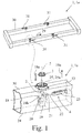
- a component carrier 1 in particular a Aufspannrahmen 1a for aircraft structural components, shown with four centering arrangements of a proposed processing station.
- the Fig. 1 In addition, an enlarged oblique view of one of these centering arrangements in the component carrier 1 again.
- the clamping frame 1a shown is used in a - not shown here - processing station for aircraft structural components.
- the aircraft structure components which can be accommodated by this mounting frame 1a include in particular the fuselage and wings of an aircraft as well as their components.
- the proposed centering arrangement comprises a centering pin 2 and a centering 3 for the centering pin 2, which in each case in the Fig. 2b and 2a enlarged are reproduced.
- the centering receptacle 3 is thus adapted to receive the centering pin 2 in its opening.
- the centering receptacle 3 is in this case arranged on the workpiece side and thus associated with the workpiece and in particular with the aircraft structural component. It may be at this centering 3 to a corresponding receptacle and opening on the workpiece itself or as in the Fig. 1 shown to act a separate component with such an opening, which is releasably secured to the workpiece in a suitable manner prior to machining the workpiece.
- the centering 3 can also be part of a - not shown here - with several such centering 3, which intermediate harness can then be connected as a whole in advance in a suitable manner with the workpiece.
- the proposed centering comprises a rotary drive 4 for rotation of the centering pin 2 about a - geometrically to be understood - longitudinal axis 5 of the centering pin 2, so that the centering pin 2 can be brought by the rotation in a centering engagement with the centering 3.
- the longitudinal axis 5 corresponds here to the main expansion direction of the centering pin 2, in particular from the Fig. 1 evident.
- engagement is to be understood here first of all as a mechanical contact between the centering pin 2 and the centering receptacle 3. This engagement is centering insofar as it leads to a mechanical displacement of the centering 3, for example by pressing, in a predefined and thus centered position in at least one dimension relative to the centering pin 2, if the centering 3 does not already centered in this sense is.
- this centered position on the longitudinal axis 5 of the centering pin 2 so that in the centered state, the course of the longitudinal axis 5 of the centering pin 2 corresponding axis of the centering 3 in any case in said, at least one dimension corresponding to the course of the longitudinal axis 5 of the centering pin 2 , With a centering in two Consequently, dimensions, ie in the surface, would coincide with the corresponding axis of the centering receptacle 3 in the centered position with the longitudinal axis 5. An established centering intervention in this sense is approximately in the Fig. 4d played.
- the centering engagement is preferably carried out so that the rotation of the centering pin 2 is not blocked by the centering 3, but the centering pin 2 could continue to rotate, in which case the centering can be solved again.
- the rotation of the centering pin 2 causes an increase in the effective extent of the centering pin 2 in the direction to be centered.
- this expansion of the centering pin 2 in its nominal size has reached the extent of the corresponding opening of the centering 3, whereby a centering of the centering 3 is enforced.
- a further rotation of the centering pin 2 then leads to a reduction of this effective extent in the centering direction.
- the centering pin 2 has a closing contour 6 and the centering receptacle 3 has a mating contour 7a, b for producing the centering engagement.
- a closing contour 6 and two alternative mating contours 7a, b are exemplary in the Fig. 5a-b shown.
- the closing contour 6 here represents the cross-sectional contour of the centering pin 2.
- the counter contour 7 a, b is accordingly the cross-sectional contour of the centering receptacle 3.
- This particularly preferred embodiment preferably further provides that the closing contour 6 defines a maximum outer closing radius 8a and the mating contour 7 defines a minimum inner contact radius 8b about the longitudinal axis 5, wherein the closing radius 8a does not exceed the contact radius 8b.
- the closing contour 6 defines a maximum outer closing radius 8a and the mating contour 7 defines a minimum inner contact radius 8b about the longitudinal axis 5, wherein the closing radius 8a does not exceed the contact radius 8b.
- the closing contour 6 defines a maximum outer closing radius 8a and the mating contour 7 defines a minimum inner contact radius 8b about the longitudinal axis 5, wherein the closing radius 8a does not exceed the contact radius 8b.
- the nominal size of the closing radius 8a the nominal size of the contact radius 8b, so that deviations are only due to manufacturing tolerances and move within this. It should be noted that for both shown counter contours 7a, b the contact radius 8b is identical.
- the closing radius 8a of the closing contour 6 in this sense denotes the radius with respect to the longitudinal axis 5, within which the closing contour 6 is completely encompassed. In other words, the closing contour 6 has no component which is radially further away from the longitudinal axis 5 than the closing radius 8a.
- the contact radius 8b of the mating contour 7a, b designates that radius with respect to the same longitudinal axis 5, outside of which the mating contour 7a, b forms in its entirety. In other words, the mating contour 7a, b has no component which is radially closer to the longitudinal axis 5 than the contact radius 8b.
- the closing radius 8a does not exceed the contact radius 8b, it is ensured that in any case no positive connection between the closing contour 6 and the mating contour 7a, b of the rotation of the centering pin 2 in the centering 3 for producing the centering engagement or a further rotation of the centering pin 2 can oppose.
- An actual collision between centering pin 2 and centering 3 during rotation or even snagging is thereby excluded. Rather, this is promoted by the fact that with the rotation of the centering pin 2, the centering 3 can move relative to the centering pin 2 so that the desired centering is achieved.
- the closing contour 6 forms a polygon 6a and preferably a square.
- a polygon 6a is adapted to be brought into a position with such a centering engagement by a rotation by an angle of rotation, which is defined by the number of edges of the polygon 6a, from a position in which there is no centering engagement in the sense of the proposal become. This is particularly facilitated by the fact that the polygon 6a, as in the Fig. 5a, b and Fig. 2b can be seen, rounded corners 6b has.
- the mating contour 7a, b it is correspondingly preferred for the mating contour 7a, b to have inwardly projecting contact projections 9, the number of edges of the polygon 6a corresponding at least, and preferably precisely, to the number of contact projections 9.
- "Projecting inwards” in this context means that the contact projections 9 point radially in the direction of the longitudinal axis 5 and that between these contact projections 9 with respect to this radial direction recessed portions of the mating contour 7a, b are present, which will be discussed in more detail below.
- the centering engagement between the centering pin 2 and the centering 3 is made in a centering direction 10a, which extends radially to the longitudinal axis 5 and the longitudinal axis 5 intersects.
- the centering 3 is thus inevitably shifted so that the centering occurs in this centering 10a and after making the centering engagement another relative movement - apart from negligible displacements due to manufacturing tolerances - in this centering 10a by just centering this Intervention is prevented.
- the statement that the centering direction 10a extends radially to the longitudinal axis 5 and intersects the longitudinal axis 5 could also be formulated such that the centering direction 10a is a radial direction of the longitudinal axis 5.
- a first possibility of the preferred embodiment now provides that in the form-fit a clearance 11 - which goes beyond the production-justified distance - between the centering pin 2 and the centering 3 in a game direction 12 is present, the game direction 12 extends radially to the longitudinal axis 5 and the longitudinal axis 5 intersects.
- this is equivalent to the observation that the play direction 12 is a radial direction of the longitudinal axis 5.
- this first preferred option is thus a Relative movement between the centering pin 2 and the centering 3 in the centering direction 10a prevents, in the game direction 12 but in principle allowed.
- a variant according to this first possibility in which - as also preferred - the game direction 12 to the centering direction 10 a is rectangular, is in the Fig. 5b shown.
- a second possibility of the preferred embodiment again which is exemplified in the Fig. 5a is shown, provides that the positive connection between the centering pin 2 and the centering 3 is made in a further centering direction 10b, which further centering direction 10b extends radially to the longitudinal axis 5 and at right angles to the centering direction 10a and the longitudinal axis 5 intersects. It is therefore also in the other centering direction 10b to a radial direction of the longitudinal axis 5.Auch in this further centering direction 10b is provided that when the centering engagement between the centering pin 2 and the centering 3 is made, the nominal size of the centering pin 2 of the centering 3 corresponds.
- the centering arrangement In order to avoid a relative movement between the centering pin 2 and the centering receptacle 3 from the area defined by the two centering directions 10a, b, but especially in the direction of the longitudinal axis 5, it is further preferred for the centering arrangement to be perpendicular to the longitudinal axis 5 Clamping surface 13 and the centering a locking device 14 for locking the centering 3 with respect to a, preferably vertical, movement relative to the clamping surface 13 has.
- This clamping surface 13 is to be understood as a, potentially only edge or web-shaped surface in the sense of a surface against which the locking device 14, for example by a frictional connection, prevents movement of the centering 3. Indirectly, such a movement of the workpiece is prevented.
- a locking of the centering receptacle 3 with respect to a, preferably vertical movement relative to the clamping surface 13 in the direction of the longitudinal axis 5 may be provided.
- a locking of the workpiece on the component carrier 1 is achieved.
- the locking device 14 comprises an engagement contour 15 on the centering pin 2 for engaging behind the centering receptacle 3.
- Such an engagement contour 15 is clearly in the Fig. 2b as well as the Fig. 4a-b recognizable.
- the centering 3 is thus not only used for the centering engagement with the closing contour 6 but also to be engaged behind by the engagement contour 15. This in turn makes it possible to press the centering receptacle 3 against the clamping surface 13, for example, by means of a force applied to the centering receptacle 3 by means of the engagement contour 15, thereby bringing about the desired locking.
- the already provided for the centering engagement counter contour 7a, b with their approximately in the Fig. 2b shown contact projections 9 of the centering 3 are also used for the latch described here in a dual function, if, as preferred, the engagement contour 15th for engaging behind the mating contour 7a, b and in particular is arranged for engaging behind the contact projections 9. Then the same formations of the mating contour 7a, b - in this case the contact projections 9 - both for the centering engagement - in cooperation with the closing contour 6 - and for the lock - in cooperation with the engagement contour 15 - to use.
- the centering effect also benefits the positioning of the engagement contour 15 with respect to the contact projections 9.
- the dual function may additionally consist in the use of the same rotational movement for the centering engagement and the engagement behind.
- the engagement contour 15 is adapted to engage behind the contact projections 9, when the centering pin 2 is brought by the rotation in the centering engagement with the Zentrier innovation 3.
- the juxtaposition of Fig. 4a, b on the one hand and the Fig. 4c, d on the other hand illustrates how the same rotation causes both the centering engagement and the engaging behind.
- a preferred - and also in the Fig. 2b shown - engagement contour 15 has gripping projections 16 which extend from the longitudinal axis 5 in the radial direction and are adapted to engage behind the contact projections 9 when the centering pin 2 is brought by the rotation in the centering engagement with the centering 3.
- This embodiment fits well with a corresponding, in the Fig. 2a illustrated and also preferred embodiment of the mating contour 7a, b, which recesses 17 between the contact projections 9 provides.
- a particularly suitable coordination of these components to each other is given if the recesses 17 correspond to the gripping projections 16 insofar that the engagement contour 15 can be brought by the rotation of the centering pin 2 about the longitudinal axis 5 in a position to the mating contour 7, wherein the gripping projections 16 are aligned with the recesses 17 and the engagement contour 15 can be moved through the mating contour 7a, b.
- This situation is in the Fig. 4a played.
- the centering pin 2 can be rotated so that a movement of the centering pin 2 in the direction of the longitudinal axis 5 is possible, in which the engagement contour 15 can be moved specifically with their gripping projections 16 on the mating contour 7a, b over.
- the locking device likewise produced by the centering arrangement must ensure that the workpiece received by the component carrier 1, that is to say, for example, an aircraft structural component, does not fall off the component carrier 1. This should also apply in the event of an unexpected power loss at the processing station, such as a power failure or the operation of an emergency stop button.
- the centering arrangement has a biasing spring 18, which is adapted to a force and in particular a bias, on the centering pin 2 in a direction to the clamping surface 13 direction 18 a, which in the Fig. 1 is excellent to exercise.
- the biasing spring 18 is arranged such that it pushes away an intermediate carrier 18b connected to the centering pin 2 from a rear side of the clamping surface 13, as a result of which the centering pin 2 is biased in said direction 18a.
- a force must be expended to move the centering pin 2 from the locking situation, so that in the event of failure of all engines alone by the biasing spring 18 a lock is guaranteed if the centering pin 2 is in a corresponding engagement with the centering 3.
- the centering arrangement has a linear drive 19 for moving the centering pin 2 along the longitudinal axis 5.
- the linear drive 19 may be arranged on an end of the centering pin 2 opposite the engagement contour 15, and thus preferably also on the closing contour 6.
- the linear drive 19 is adapted to move the centering pin 2 in a direction 19b facing away from the clamping surface 13. It makes special sense that the Linear drive 19 attaches to the same intermediate carrier 18b as well as the said biasing spring 18th
- the deflection arm 20 may be connected at a radially outer end via a rotary joint 21 with a lifting rod 22. This is especially true in the Fig. 1 to recognize.
- the lifting rod 22 in turn can - as shown - be connected to a corresponding linear motor 23.
- a further preferred embodiment of the proposed centering arrangement comprises a guide 25, 26, which is adapted to align the centering 3 on the longitudinal axis 5 of the centering pin 2.
- the shape of the referrer 25, 26 may be dependent on the position of the centering arrangement on the Aufspannrahmen 1a.
- the proposed centering on the Aufspannrahmen 1a has a vertical, upward orientation, determined by the longitudinal axis 5 of the centering pin 2, then the Einweiser 25 as shown in FIG Fig. 6a be configured in the form of a ring 25 a, which has a tapered inner surface 27. An approaching from above centering 3 then slides on this tapered inner surface in the direction of the center of the Einweisers 25, whereby a pertinent advance direction of the centering 3 is effected, after which the centering pin 2 is aligned with the opening of the Zentrier matter 3.
- the proposed centering arrangement may also have a horizontal orientation on the Aufspannrahmen 1a, in turn determined by the longitudinal axis 5 of the centering pin 2.
- the Einweiser 26 according to the illustration of Fig. 6b be configured in the form of a U-shaped fold.
- the open side 28 of the U-shaped fold then also points in the vertical direction to the top, from which direction the centering 3 is regularly guided in the guide 26. Further embodiments of such referrers are also conceivable.
- a chucking frame 1a for aircraft structural components such as in FIGS Fig. 1 shown, to call with a frame housing 24 in a rectangular shape and a plurality of proposed centering arrangements.
- a preferred further development of such a mounting frame 1a provides that the respective clamping surface 13 of the centering arrangements form part of an outer surface 30 of the frame housing 24. If then, as preferred and in the Fig. 1 3, the respective clamping surfaces 13 of the centering arrangements point in the same direction, the centering arrangements can be used for centering an aircraft structural component brought onto the mounting frame 1 a from this direction.
- a further preferred development of the Aufspannrahmens 1a further provides that the Aufspannrahmen 1a has a linear motor 23 for the actuation of a Umlenkarms 20, wherein the linear motor 23 is disposed within the frame housing 24 in a side direction 29 of the rectangular shape.
- the centering and locking can be done fully automatically.
- a lateral direction 29 of the rectangular shape is to be understood as meaning any direction which corresponds to the extent of one of the four rectangular sides of the rectangular shape of the clamping frame 1a.
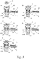
- Fig. 3a-e such as Fig. 4a-d a corresponding proposal according to the method for centering and locking a centering 2 by a centering pin 2 on a clamping surface 13, in particular on the clamping surface 13 of a component carrier 1, explained.
- the said proposed method now comprises moving the centering pin 2 through the centering receptacle 3, so that gripping projections 16 of an engagement contour 15 of the centering pin 2 are guided through recesses 17 of a mating contour 7a, b of the centering receptacle 3.
- This process step takes place as a transition between the state in the Fig. 3b and the state in the Fig. 3c , In particular, this movement can take place against a - already described above - bias of a biasing spring 18, according to the embodiment of Fig. 3 caused by the linear actuator 19.
- the proposed method comprises rotating the centering pin 2 about a longitudinal axis 5 of the centering pin 2, whereby a closing contour 6 of the centering pin 2 with the mating contour 7a, b of the centering 3 is brought into centering engagement and at the same time the gripping projections 16, the mating contour 7a, b engage behind.
- This process step takes place between the representation of Fig. 3c and those of Fig. 3d instead of.
- the corresponding transition - based on the engaging behind the mating contour 7a, b - from a comparison of Fig. 4a with the Fig. 4b and - based on the centering intervention - from a comparison of Fig. 4c with the Fig. 4d to recognize.
- the proposed method comprises pressing the centering 3 against the clamping surface 13 by a movement of the centering pin 2.
- This step corresponds to the transition from the situation of Fig. 3d to the one of Fig. 3e , This movement can be effected in particular and as already described by the bias of the biasing spring 18.
- the linear drive 19 does not have to act in this direction, but only turn off the previously directed against the biasing spring 18 force again.
Landscapes
- Engineering & Computer Science (AREA)
- Mechanical Engineering (AREA)
- Manufacturing & Machinery (AREA)
- Transportation (AREA)
- Aviation & Aerospace Engineering (AREA)
- Jigs For Machine Tools (AREA)
- Automatic Assembly (AREA)
Claims (15)
- Poste de traitement pour composant structurel d'avion, présentant un ensemble de centrage de porte-composant (1), en particulier pour un cadre de serrage (1a) de composant structurel d'avion, un goujon de centrage (2), un logement de centrage (3) pour le goujon de centrage (2) et un entraînement en rotation (4) qui fait tourner le goujon de centrage (2) autour d'un axe longitudinal (5) du goujon de centrage (2) de telle sorte que le goujon de centrage (2) puisse être amené par sa rotation à engager le logement de centrage (3) et s'y centrer, le goujon de centrage (2) présentant un contour de fermeture (6) et le logement de centrage (3) un contour complémentaire (7a, b) qui permet d'établir l'engagement de centrage.
- Poste de traitement selon la revendication 1, caractérisé en ce que le contour de fermeture (6) définit un rayon maximal extérieur de fermeture (8a) et le contour complémentaire (7a, b) un rayon minimum intérieur de contact (8b) autour de l'axe longitudinal (5), le rayon de fermeture (8a) ne dépassant pas le rayon de contact (8b).
- Poste de traitement selon la revendication 2, caractérisé en ce que le contour de fermeture (6) forme une section transversale polygonale (6a), de préférence une section transversale carrée, la section transversale polygonale (6a) présentant des sommets (6b) arrondis.
- Poste de traitement selon la revendication 3, caractérisé en ce que le contour complémentaire (7a, b) présente des saillies de contact (9) débordant vers l'intérieur, le nombre des côtés de la section transversale polygonale (6a) correspondant au moins et de préférence exactement au nombre des saillies de contact (9).
- Poste de traitement selon l'une des revendications 1 à 4, caractérisé en ce que l'engagement de centrage entre le goujon de centrage (2) et le logement de centrage (3) s'établit dans une direction de centrage (10a), la direction de centrage (10a) s'étendant radialement par rapport à l'axe longitudinal (5) et intersectant l'axe longitudinal (5).
- Poste de traitement selon la revendication 5, caractérisé en ce que lors de l'engagement de centrage, une distance libre (11) est prévue entre le goujon de centrage (2) et le logement de centrage (3) dans une direction de jeu (12) de préférence orthogonale à la direction de centrage (10a), la direction de jeu (12) s'étendant radialement par rapport à l'axe longitudinal (5) et intersectant l'axe longitudinal (5).
- Poste de traitement selon la revendication 5, caractérisé en ce que l'engagement de centrage entre le goujon de centrage (2) et le logement de centrage (3) s'établit dans une autre direction de centrage (10b), cette autre direction de centrage (10b) s'étendant radialement par rapport à l'axe longitudinal (5) et orthogonalement par rapport à la direction de centrage (10a) et intersectant l'axe longitudinal (5).
- Poste de traitement selon l'une des revendications 1 à 7, caractérisé en ce que l'ensemble de centrage présente une surface de serrage (13) disposée perpendiculairement à l'axe longitudinal (5) et en ce que l'agencement de centrage présente un ensemble de verrouillage (14) qui verrouille le logement de centrage (3) pour un déplacement par rapport à la surface de serrage (13), de préférence perpendiculaire à cette dernière.
- Poste de traitement selon la revendication 8, caractérisé en ce que l'ensemble de verrouillage (14) comporte un contour d'engagement (15) sur le goujon de centrage (2) en vue d'accrocher le logement de centrage (3) par l'arrière, le contour d'engagement (15) étant disposé dans la direction de l'axe longitudinal (5) en décalage par rapport au contour de fermeture (6), le contour d'engagement (15) étant destiné à accrocher par l'arrière le contour complémentaire (7a, b), en particulier les saillies de contact (9), et en outre, le contour d'engagement (15) est conçu pour accrocher par l'arrière les saillies de contact (9) lorsque le goujon de centrage (2) est amené par la rotation à engager le logement de centrage (3) et à s'y centrer.
- Poste de traitement selon la revendication 9, caractérisé en ce que le contour d'engagement (15) présente des saillies d'engagement (16) qui débordent de l'axe longitudinal (5) dans la direction radiale et qui sont destinés à accrocher par l'arrière les saillies de contact (9) lorsque le goujon de centrage (2) est amené par sa rotation à engager le logement de centrage (3) et à s'y centrer, et en ce que de préférence, le contour complémentaire (7a, b) présente des découpes (17) entre les saillies de contact (9), les découpes (17) correspondant en particulier aux saillies d'engagement (16) de telle sorte que le contour d'engagement (15) puisse être amené du fait de la rotation du goujon de centrage (2) autour de l'axe longitudinal (5) dans une position par rapport au contour complémentaire (7a, b) dans laquelle les saillies d'engagement (16) sont alignées sur les découpes (17) et le contour d'engagement (15) peut être déplacé par le contour complémentaire (7a, b).
- Poste de traitement selon l'une des revendications 8 à 10, caractérisé en ce que l'ensemble de centrage présente un ressort de précontrainte (18) destiné à exercer une force et en particulier une précontrainte sur le goujon de centrage (2), dans une direction (18b) orientée vers la surface de serrage (13).
- Poste de traitement selon l'une des revendications 8 à 11, caractérisé en ce que l'ensemble de centrage présente un entraînement linéaire (19) qui déplace le goujon de centrage (2) le long de l'axe longitudinal (5), l'entraînement linéaire (19) étant de préférence disposé à une extrémité du goujon de centrage (2) située face au contour d'engagement (15), et en particulier en ce que l'entraînement linéaire (19) est destiné à déplacer le goujon de centrage (2) dans une direction (19a) s'éloignant de la surface de serrage (13).
- Poste de traitement selon l'une des revendications 1 à 12, caractérisé en ce que l'entraînement en rotation (4) présente sur le goujon de centrage (2) un bras de renvoi (20) disposé radialement par rapport à l'axe longitudinal (5) et de préférence en ce que le bras de renvoi (20) est relié à une extrémité radialement extérieure par une articulation en rotation (21) dotée d'une tige de déplacement (22).
- Poste de traitement selon l'une des revendications 1 à 10, caractérisé en ce que l'ensemble de centrage comporte un indicateur (25, 26) conçu pour aligner le logement de centrage (3) sur l'axe longitudinal (5) du goujon de centrage (2).
- Procédé de centrage et de verrouillage au moyen d'un ensemble de centrage d'un poste de traitement de composant structurel d'avion, l'ensemble présentant un goujon de centrage (2) et un logement de centrage (3), le procédé comportant pour centrer et verrouiller le logement de centrage (3) par le goujon de centrage (2) sur une surface de serrage (13) et en particulier sur la surface de serrage (13) d'un porte-composant (1) les étapes suivantes :déplacement, en particulier en opposition à une précontrainte d'un ressort de précontrainte (18), du goujon de centrage (2) à travers le logement de centrage (3) de telle sorte que des saillies d'engagement (16) d'un contour d'engagement (15) du goujon de centrage (2) soient guidées par des découpes (17) d'un contour complémentaire (7a, b) du logement de centrage (3),rotation du goujon de centrage (2) autour d'un axe longitudinal (5) du goujon de centrage (2) ce qui amène un contour de fermeture (6) du goujon de centrage (2) à engager le contour complémentaire (7a, b) du logement de centrage (3) et à s'y centrer, en même temps que les saillies d'engagement (16) accrochent par l'arrière le contour complémentaire (7a, b) etpoussée du logement de centrage (3) contre la surface de serrage (13) par un déplacement du goujon de centrage (2) réalisé en particulier par la précontrainte du ressort de précontrainte (18).
Applications Claiming Priority (1)
| Application Number | Priority Date | Filing Date | Title |
|---|---|---|---|
| DE102013108003.0A DE102013108003A1 (de) | 2013-07-26 | 2013-07-26 | Zentrieranordnung für einen Bauteilträger |
Publications (2)
| Publication Number | Publication Date |
|---|---|
| EP2829357A1 EP2829357A1 (fr) | 2015-01-28 |
| EP2829357B1 true EP2829357B1 (fr) | 2017-11-01 |
Family
ID=51211085
Family Applications (1)
| Application Number | Title | Priority Date | Filing Date |
|---|---|---|---|
| EP14177443.0A Active EP2829357B1 (fr) | 2013-07-26 | 2014-07-17 | Poste d`usinage pour les composantes structurelles d`avion avec un système de centrage pour un porte-composant |
Country Status (7)
| Country | Link |
|---|---|
| US (1) | US9604734B2 (fr) |
| EP (1) | EP2829357B1 (fr) |
| JP (1) | JP5955354B2 (fr) |
| CN (1) | CN104339187B (fr) |
| DE (1) | DE102013108003A1 (fr) |
| ES (1) | ES2652175T3 (fr) |
| RU (1) | RU2685921C2 (fr) |
Families Citing this family (6)
| Publication number | Priority date | Publication date | Assignee | Title |
|---|---|---|---|---|
| DE102013108003A1 (de) | 2013-07-26 | 2015-01-29 | Brötje-Automation GmbH | Zentrieranordnung für einen Bauteilträger |
| US9751641B2 (en) * | 2015-05-07 | 2017-09-05 | The Boeing Company | Automated index pin locking apparatus |
| JP7051287B2 (ja) * | 2016-12-05 | 2022-04-11 | 株式会社ソニー・インタラクティブエンタテインメント | システム、治具、および情報処理方法 |
| USD828421S1 (en) * | 2016-12-08 | 2018-09-11 | Carlton C. Musser | Vertical seam welder component |
| CN106808185B (zh) * | 2017-03-22 | 2023-03-21 | 安徽航大智能科技有限公司 | 一种复合变速箱夹取翻转机构 |
| FR3086877A1 (fr) * | 2018-10-09 | 2020-04-10 | Psa Automobiles Sa | Dispositif de positionnement rapide |
Citations (1)
| Publication number | Priority date | Publication date | Assignee | Title |
|---|---|---|---|---|
| US4598453A (en) * | 1984-12-21 | 1986-07-08 | E. I. Du Pont De Nemours And Company | Apparatus for centering and aligning a workpiece |
Family Cites Families (17)
| Publication number | Priority date | Publication date | Assignee | Title |
|---|---|---|---|---|
| DE2820218A1 (de) * | 1978-05-09 | 1979-11-15 | Springfix Befestigungstechnik | Befestigungselement zur loesbaren verbindung von zwei plattenartigen bauteilen |
| JPS5713129U (fr) * | 1980-06-24 | 1982-01-23 | ||
| JPH0751217Y2 (ja) * | 1990-07-10 | 1995-11-22 | 日立精機株式会社 | 工作機械のパレットクランプ装置 |
| JPH0489636U (fr) * | 1990-12-17 | 1992-08-05 | ||
| RU2201322C2 (ru) * | 2000-03-28 | 2003-03-27 | Самарский государственный технический университет | Способ установки детали по плоскости и отверстиям |
| JP4094340B2 (ja) * | 2002-02-13 | 2008-06-04 | 株式会社コスメック | クランプの動作検出装置 |
| DE20215718U1 (de) * | 2002-10-12 | 2003-02-27 | Hohenstein Vorrichtungsbau Und Spannsysteme Gmbh, 09337 Hohenstein-Ernstthal | Bajonett-Schwenkzugspanner |
| US7934710B2 (en) * | 2005-01-24 | 2011-05-03 | Verigy (Singapore) Pte. Ltd. | Clamp and method for operating same |
| RU2302939C1 (ru) * | 2006-01-25 | 2007-07-20 | Открытое акционерное общество "КАМАЗ" | Устройство для базирования и закрепления деталей |
| DE102007015672B3 (de) * | 2007-03-31 | 2008-11-27 | Fette Gmbh | Vorrichtung für den Ablauf von Preßlingen aus einer Rundläuferpresse |
| US8220134B2 (en) | 2008-06-12 | 2012-07-17 | Gemcor Ii, Llc | Flexible fastening machine tool |
| DE202008013438U1 (de) * | 2008-10-13 | 2010-02-25 | Kuka Systems Gmbh | Handhabungseinrichtung für Flugzeugteile |
| CN201301851Y (zh) * | 2008-11-21 | 2009-09-02 | 成都飞机工业(集团)有限责任公司 | 一种弹簧定位销 |
| FR2945760B1 (fr) * | 2009-05-20 | 2011-06-10 | Christophe Gaillard | Dispositif de fixation rapide par serrage d'un organe |
| FR2966073A1 (fr) * | 2010-10-14 | 2012-04-20 | Christophe Gaillard | Dispositif de fixation rapide a effort de serrage amplifie. |
| EP2505302B1 (fr) * | 2011-03-29 | 2014-01-08 | SMW-AUTOBLOK Spannsysteme GmbH | Lunette |
| DE102013108003A1 (de) | 2013-07-26 | 2015-01-29 | Brötje-Automation GmbH | Zentrieranordnung für einen Bauteilträger |
-
2013
- 2013-07-26 DE DE102013108003.0A patent/DE102013108003A1/de not_active Withdrawn
-
2014
- 2014-07-17 EP EP14177443.0A patent/EP2829357B1/fr active Active
- 2014-07-17 ES ES14177443.0T patent/ES2652175T3/es active Active
- 2014-07-24 RU RU2014130445A patent/RU2685921C2/ru active
- 2014-07-25 US US14/341,602 patent/US9604734B2/en active Active
- 2014-07-28 CN CN201410361687.1A patent/CN104339187B/zh active Active
- 2014-07-28 JP JP2014152917A patent/JP5955354B2/ja active Active
Patent Citations (1)
| Publication number | Priority date | Publication date | Assignee | Title |
|---|---|---|---|---|
| US4598453A (en) * | 1984-12-21 | 1986-07-08 | E. I. Du Pont De Nemours And Company | Apparatus for centering and aligning a workpiece |
Also Published As
| Publication number | Publication date |
|---|---|
| JP5955354B2 (ja) | 2016-07-20 |
| ES2652175T3 (es) | 2018-01-31 |
| RU2685921C2 (ru) | 2019-04-23 |
| CN104339187A (zh) | 2015-02-11 |
| US20150026961A1 (en) | 2015-01-29 |
| CN104339187B (zh) | 2019-02-22 |
| JP2015024492A (ja) | 2015-02-05 |
| EP2829357A1 (fr) | 2015-01-28 |
| RU2014130445A (ru) | 2016-02-20 |
| DE102013108003A1 (de) | 2015-01-29 |
| US9604734B2 (en) | 2017-03-28 |
Similar Documents
| Publication | Publication Date | Title |
|---|---|---|
| DE60301090T2 (de) | Vorrichtung zum Stanznieten | |
| DE3421452C2 (de) | Vorrichtung zum automatischen Erfassen bzw. Lösen eines Werkzeugträgers bei einem Manipulator | |
| EP2829357A1 (fr) | Système de centrage pour un porte-composant | |
| EP2078585B1 (fr) | Dispositif mécanique destiné au montage et/ou au démontage d'une tuyère laser et machine de traitement laser dotée d'un tel dispositif mécanique | |
| EP3180138B1 (fr) | Outil de cintrage et dispositif de préhension servant à manipuler l'outil de cintrage | |
| AT515177A1 (de) | Antriebssystem sowie damit ausgerüstete Profilieranlage | |
| AT514821B1 (de) | Biegepresse und Biegeverfahren | |
| EP3658462B1 (fr) | Installation d'usinage pour éléments structuraux d'avions | |
| DE4002075A1 (de) | Handhabungsvorrichtung und verfahren zum handhaben von werkstuecken | |
| EP1716991A1 (fr) | Système de fabrication de pièces en forme de plaque | |
| EP3124170A1 (fr) | Magasin a chaine pour la reception d'outils | |
| WO2018055182A1 (fr) | Outil et machine-outil, ainsi que procédé de découpe et/ou de formage de pièces en forme de plaque | |
| EP2905088A2 (fr) | Système et procédé de changement d'outils et laminoir de forge | |
| DE102015121287A1 (de) | Vorrichtung zum automatisierten An- und Abkoppeln eines Werkzeugaufsatzes sowie Verfahren zum automatisierten Verbinden wenigstens zweier Werkstücke | |
| DE102010006079B4 (de) | Bearbeitungsvorrichtung zum Bearbeiten von Endbereichen von sich entlang einer Längsachse erstreckenden Hohlkörpern | |
| EP1117497B1 (fr) | Dispositif d'aboutage, procede d'aboutage par enchevetrement et assemblage realise par aboutage par enchevetrement | |
| DE102018209874B4 (de) | Werkzeugwechsel- und Haltevorrichtung sowie Robotersystem | |
| DE102013209111B4 (de) | Einspannvorrichtung, insbesondere zur Aufnahme und zum Einspannen eines Bauteils, sowie Einspannsystem mit einer solchen Einspannvorrichtung | |
| DE102019124347B4 (de) | Vorrichtung zur Montage von wenigstens einer zumindest zwei Fahrzeugbauteile umfassenden Fahrzeugbauteilgruppe an einer Fahrzeugrohstruktur | |
| DE1502010A1 (de) | Werkzeugmaschine mit automatischem Werkzeugwechsel | |
| WO2019020423A2 (fr) | Station de moulage de filet | |
| EP3108995A2 (fr) | Machine d'usinage | |
| WO2014019693A1 (fr) | Poste de caisses brutes pour la construction de caisses brutes de véhicules automobiles et procédé permettant de faire fonctionner ledit poste de caisses brutes | |
| EP3956084A1 (fr) | Tête de pose, fiche de presse ou dispositif de pose pourvu de cette tête de pose et procédé d'assemblage d'un élément d'assemblage pourvu de la tête de pose | |
| EP2792627B1 (fr) | Dispositif d'amarrage |
Legal Events
| Date | Code | Title | Description |
|---|---|---|---|
| 17P | Request for examination filed |
Effective date: 20140717 |
|
| AK | Designated contracting states |
Kind code of ref document: A1 Designated state(s): AL AT BE BG CH CY CZ DE DK EE ES FI FR GB GR HR HU IE IS IT LI LT LU LV MC MK MT NL NO PL PT RO RS SE SI SK SM TR |
|
| AX | Request for extension of the european patent |
Extension state: BA ME |
|
| PUAI | Public reference made under article 153(3) epc to a published international application that has entered the european phase |
Free format text: ORIGINAL CODE: 0009012 |
|
| R17P | Request for examination filed (corrected) |
Effective date: 20150724 |
|
| RBV | Designated contracting states (corrected) |
Designated state(s): AL AT BE BG CH CY CZ DE DK EE ES FI FR GB GR HR HU IE IS IT LI LT LU LV MC MK MT NL NO PL PT RO RS SE SI SK SM TR |
|
| RAP1 | Party data changed (applicant data changed or rights of an application transferred) |
Owner name: BROETJE-AUTOMATION GMBH |
|
| 17Q | First examination report despatched |
Effective date: 20161212 |
|
| GRAP | Despatch of communication of intention to grant a patent |
Free format text: ORIGINAL CODE: EPIDOSNIGR1 |
|
| INTG | Intention to grant announced |
Effective date: 20170623 |
|
| GRAS | Grant fee paid |
Free format text: ORIGINAL CODE: EPIDOSNIGR3 |
|
| GRAA | (expected) grant |
Free format text: ORIGINAL CODE: 0009210 |
|
| AK | Designated contracting states |
Kind code of ref document: B1 Designated state(s): AL AT BE BG CH CY CZ DE DK EE ES FI FR GB GR HR HU IE IS IT LI LT LU LV MC MK MT NL NO PL PT RO RS SE SI SK SM TR |
|
| REG | Reference to a national code |
Ref country code: GB Ref legal event code: FG4D Free format text: NOT ENGLISH |
|
| REG | Reference to a national code |
Ref country code: CH Ref legal event code: EP Ref country code: AT Ref legal event code: REF Ref document number: 941584 Country of ref document: AT Kind code of ref document: T Effective date: 20171115 |
|
| REG | Reference to a national code |
Ref country code: IE Ref legal event code: FG4D Free format text: LANGUAGE OF EP DOCUMENT: GERMAN |
|
| REG | Reference to a national code |
Ref country code: DE Ref legal event code: R096 Ref document number: 502014006026 Country of ref document: DE |
|
| REG | Reference to a national code |
Ref country code: ES Ref legal event code: FG2A Ref document number: 2652175 Country of ref document: ES Kind code of ref document: T3 Effective date: 20180131 |
|
| REG | Reference to a national code |
Ref country code: NL Ref legal event code: MP Effective date: 20171101 |
|
| REG | Reference to a national code |
Ref country code: LT Ref legal event code: MG4D |
|
| PG25 | Lapsed in a contracting state [announced via postgrant information from national office to epo] |
Ref country code: NL Free format text: LAPSE BECAUSE OF FAILURE TO SUBMIT A TRANSLATION OF THE DESCRIPTION OR TO PAY THE FEE WITHIN THE PRESCRIBED TIME-LIMIT Effective date: 20171101 Ref country code: LT Free format text: LAPSE BECAUSE OF FAILURE TO SUBMIT A TRANSLATION OF THE DESCRIPTION OR TO PAY THE FEE WITHIN THE PRESCRIBED TIME-LIMIT Effective date: 20171101 Ref country code: NO Free format text: LAPSE BECAUSE OF FAILURE TO SUBMIT A TRANSLATION OF THE DESCRIPTION OR TO PAY THE FEE WITHIN THE PRESCRIBED TIME-LIMIT Effective date: 20180201 Ref country code: FI Free format text: LAPSE BECAUSE OF FAILURE TO SUBMIT A TRANSLATION OF THE DESCRIPTION OR TO PAY THE FEE WITHIN THE PRESCRIBED TIME-LIMIT Effective date: 20171101 Ref country code: SE Free format text: LAPSE BECAUSE OF FAILURE TO SUBMIT A TRANSLATION OF THE DESCRIPTION OR TO PAY THE FEE WITHIN THE PRESCRIBED TIME-LIMIT Effective date: 20171101 |
|
| PG25 | Lapsed in a contracting state [announced via postgrant information from national office to epo] |
Ref country code: BG Free format text: LAPSE BECAUSE OF FAILURE TO SUBMIT A TRANSLATION OF THE DESCRIPTION OR TO PAY THE FEE WITHIN THE PRESCRIBED TIME-LIMIT Effective date: 20180201 Ref country code: LV Free format text: LAPSE BECAUSE OF FAILURE TO SUBMIT A TRANSLATION OF THE DESCRIPTION OR TO PAY THE FEE WITHIN THE PRESCRIBED TIME-LIMIT Effective date: 20171101 Ref country code: RS Free format text: LAPSE BECAUSE OF FAILURE TO SUBMIT A TRANSLATION OF THE DESCRIPTION OR TO PAY THE FEE WITHIN THE PRESCRIBED TIME-LIMIT Effective date: 20171101 Ref country code: GR Free format text: LAPSE BECAUSE OF FAILURE TO SUBMIT A TRANSLATION OF THE DESCRIPTION OR TO PAY THE FEE WITHIN THE PRESCRIBED TIME-LIMIT Effective date: 20180202 Ref country code: HR Free format text: LAPSE BECAUSE OF FAILURE TO SUBMIT A TRANSLATION OF THE DESCRIPTION OR TO PAY THE FEE WITHIN THE PRESCRIBED TIME-LIMIT Effective date: 20171101 Ref country code: IS Free format text: LAPSE BECAUSE OF FAILURE TO SUBMIT A TRANSLATION OF THE DESCRIPTION OR TO PAY THE FEE WITHIN THE PRESCRIBED TIME-LIMIT Effective date: 20180301 |
|
| REG | Reference to a national code |
Ref country code: FR Ref legal event code: PLFP Year of fee payment: 5 |
|
| PG25 | Lapsed in a contracting state [announced via postgrant information from national office to epo] |
Ref country code: CZ Free format text: LAPSE BECAUSE OF FAILURE TO SUBMIT A TRANSLATION OF THE DESCRIPTION OR TO PAY THE FEE WITHIN THE PRESCRIBED TIME-LIMIT Effective date: 20171101 Ref country code: DK Free format text: LAPSE BECAUSE OF FAILURE TO SUBMIT A TRANSLATION OF THE DESCRIPTION OR TO PAY THE FEE WITHIN THE PRESCRIBED TIME-LIMIT Effective date: 20171101 Ref country code: CY Free format text: LAPSE BECAUSE OF FAILURE TO SUBMIT A TRANSLATION OF THE DESCRIPTION OR TO PAY THE FEE WITHIN THE PRESCRIBED TIME-LIMIT Effective date: 20171101 Ref country code: EE Free format text: LAPSE BECAUSE OF FAILURE TO SUBMIT A TRANSLATION OF THE DESCRIPTION OR TO PAY THE FEE WITHIN THE PRESCRIBED TIME-LIMIT Effective date: 20171101 Ref country code: SK Free format text: LAPSE BECAUSE OF FAILURE TO SUBMIT A TRANSLATION OF THE DESCRIPTION OR TO PAY THE FEE WITHIN THE PRESCRIBED TIME-LIMIT Effective date: 20171101 |
|
| REG | Reference to a national code |
Ref country code: DE Ref legal event code: R097 Ref document number: 502014006026 Country of ref document: DE |
|
| PG25 | Lapsed in a contracting state [announced via postgrant information from national office to epo] |
Ref country code: RO Free format text: LAPSE BECAUSE OF FAILURE TO SUBMIT A TRANSLATION OF THE DESCRIPTION OR TO PAY THE FEE WITHIN THE PRESCRIBED TIME-LIMIT Effective date: 20171101 Ref country code: SM Free format text: LAPSE BECAUSE OF FAILURE TO SUBMIT A TRANSLATION OF THE DESCRIPTION OR TO PAY THE FEE WITHIN THE PRESCRIBED TIME-LIMIT Effective date: 20171101 Ref country code: PL Free format text: LAPSE BECAUSE OF FAILURE TO SUBMIT A TRANSLATION OF THE DESCRIPTION OR TO PAY THE FEE WITHIN THE PRESCRIBED TIME-LIMIT Effective date: 20171101 |
|
| PLBE | No opposition filed within time limit |
Free format text: ORIGINAL CODE: 0009261 |
|
| STAA | Information on the status of an ep patent application or granted ep patent |
Free format text: STATUS: NO OPPOSITION FILED WITHIN TIME LIMIT |
|
| PG25 | Lapsed in a contracting state [announced via postgrant information from national office to epo] |
Ref country code: MT Free format text: LAPSE BECAUSE OF FAILURE TO SUBMIT A TRANSLATION OF THE DESCRIPTION OR TO PAY THE FEE WITHIN THE PRESCRIBED TIME-LIMIT Effective date: 20171101 |
|
| 26N | No opposition filed |
Effective date: 20180802 |
|
| PG25 | Lapsed in a contracting state [announced via postgrant information from national office to epo] |
Ref country code: SI Free format text: LAPSE BECAUSE OF FAILURE TO SUBMIT A TRANSLATION OF THE DESCRIPTION OR TO PAY THE FEE WITHIN THE PRESCRIBED TIME-LIMIT Effective date: 20171101 |
|
| REG | Reference to a national code |
Ref country code: CH Ref legal event code: PL |
|
| PG25 | Lapsed in a contracting state [announced via postgrant information from national office to epo] |
Ref country code: MC Free format text: LAPSE BECAUSE OF FAILURE TO SUBMIT A TRANSLATION OF THE DESCRIPTION OR TO PAY THE FEE WITHIN THE PRESCRIBED TIME-LIMIT Effective date: 20171101 Ref country code: LU Free format text: LAPSE BECAUSE OF NON-PAYMENT OF DUE FEES Effective date: 20180717 |
|
| REG | Reference to a national code |
Ref country code: BE Ref legal event code: MM Effective date: 20180731 |
|
| REG | Reference to a national code |
Ref country code: IE Ref legal event code: MM4A |
|
| PG25 | Lapsed in a contracting state [announced via postgrant information from national office to epo] |
Ref country code: CH Free format text: LAPSE BECAUSE OF NON-PAYMENT OF DUE FEES Effective date: 20180731 Ref country code: IE Free format text: LAPSE BECAUSE OF NON-PAYMENT OF DUE FEES Effective date: 20180717 Ref country code: LI Free format text: LAPSE BECAUSE OF NON-PAYMENT OF DUE FEES Effective date: 20180731 |
|
| PG25 | Lapsed in a contracting state [announced via postgrant information from national office to epo] |
Ref country code: BE Free format text: LAPSE BECAUSE OF NON-PAYMENT OF DUE FEES Effective date: 20180731 |
|
| PG25 | Lapsed in a contracting state [announced via postgrant information from national office to epo] |
Ref country code: TR Free format text: LAPSE BECAUSE OF FAILURE TO SUBMIT A TRANSLATION OF THE DESCRIPTION OR TO PAY THE FEE WITHIN THE PRESCRIBED TIME-LIMIT Effective date: 20171101 |
|
| PG25 | Lapsed in a contracting state [announced via postgrant information from national office to epo] |
Ref country code: PT Free format text: LAPSE BECAUSE OF FAILURE TO SUBMIT A TRANSLATION OF THE DESCRIPTION OR TO PAY THE FEE WITHIN THE PRESCRIBED TIME-LIMIT Effective date: 20171101 Ref country code: HU Free format text: LAPSE BECAUSE OF FAILURE TO SUBMIT A TRANSLATION OF THE DESCRIPTION OR TO PAY THE FEE WITHIN THE PRESCRIBED TIME-LIMIT; INVALID AB INITIO Effective date: 20140717 |
|
| PG25 | Lapsed in a contracting state [announced via postgrant information from national office to epo] |
Ref country code: MK Free format text: LAPSE BECAUSE OF NON-PAYMENT OF DUE FEES Effective date: 20171101 |
|
| PG25 | Lapsed in a contracting state [announced via postgrant information from national office to epo] |
Ref country code: AL Free format text: LAPSE BECAUSE OF FAILURE TO SUBMIT A TRANSLATION OF THE DESCRIPTION OR TO PAY THE FEE WITHIN THE PRESCRIBED TIME-LIMIT Effective date: 20171101 |
|
| REG | Reference to a national code |
Ref country code: AT Ref legal event code: MM01 Ref document number: 941584 Country of ref document: AT Kind code of ref document: T Effective date: 20190717 |
|
| PG25 | Lapsed in a contracting state [announced via postgrant information from national office to epo] |
Ref country code: AT Free format text: LAPSE BECAUSE OF NON-PAYMENT OF DUE FEES Effective date: 20190717 |
|
| PGFP | Annual fee paid to national office [announced via postgrant information from national office to epo] |
Ref country code: ES Payment date: 20250826 Year of fee payment: 12 |
|
| PGFP | Annual fee paid to national office [announced via postgrant information from national office to epo] |
Ref country code: DE Payment date: 20250723 Year of fee payment: 12 |
|
| PGFP | Annual fee paid to national office [announced via postgrant information from national office to epo] |
Ref country code: IT Payment date: 20250724 Year of fee payment: 12 |
|
| PGFP | Annual fee paid to national office [announced via postgrant information from national office to epo] |
Ref country code: GB Payment date: 20250722 Year of fee payment: 12 |
|
| PGFP | Annual fee paid to national office [announced via postgrant information from national office to epo] |
Ref country code: FR Payment date: 20250725 Year of fee payment: 12 |