EP2829363A2 - Manually operated work device - Google Patents
Manually operated work device Download PDFInfo
- Publication number
- EP2829363A2 EP2829363A2 EP14002514.9A EP14002514A EP2829363A2 EP 2829363 A2 EP2829363 A2 EP 2829363A2 EP 14002514 A EP14002514 A EP 14002514A EP 2829363 A2 EP2829363 A2 EP 2829363A2
- Authority
- EP
- European Patent Office
- Prior art keywords
- component
- breaking point
- holding
- notch
- predetermined breaking
- Prior art date
- Legal status (The legal status is an assumption and is not a legal conclusion. Google has not performed a legal analysis and makes no representation as to the accuracy of the status listed.)
- Granted
Links
Images
Classifications
-
- B—PERFORMING OPERATIONS; TRANSPORTING
- B25—HAND TOOLS; PORTABLE POWER-DRIVEN TOOLS; MANIPULATORS
- B25F—COMBINATION OR MULTI-PURPOSE TOOLS NOT OTHERWISE PROVIDED FOR; DETAILS OR COMPONENTS OF PORTABLE POWER-DRIVEN TOOLS NOT PARTICULARLY RELATED TO THE OPERATIONS PERFORMED AND NOT OTHERWISE PROVIDED FOR
- B25F5/00—Details or components of portable power-driven tools not particularly related to the operations performed and not otherwise provided for
- B25F5/006—Vibration damping means
-
- B—PERFORMING OPERATIONS; TRANSPORTING
- B25—HAND TOOLS; PORTABLE POWER-DRIVEN TOOLS; MANIPULATORS
- B25F—COMBINATION OR MULTI-PURPOSE TOOLS NOT OTHERWISE PROVIDED FOR; DETAILS OR COMPONENTS OF PORTABLE POWER-DRIVEN TOOLS NOT PARTICULARLY RELATED TO THE OPERATIONS PERFORMED AND NOT OTHERWISE PROVIDED FOR
- B25F5/00—Details or components of portable power-driven tools not particularly related to the operations performed and not otherwise provided for
-
- B—PERFORMING OPERATIONS; TRANSPORTING
- B23—MACHINE TOOLS; METAL-WORKING NOT OTHERWISE PROVIDED FOR
- B23Q—DETAILS, COMPONENTS, OR ACCESSORIES FOR MACHINE TOOLS, e.g. ARRANGEMENTS FOR COPYING OR CONTROLLING; MACHINE TOOLS IN GENERAL CHARACTERISED BY THE CONSTRUCTION OF PARTICULAR DETAILS OR COMPONENTS; COMBINATIONS OR ASSOCIATIONS OF METAL-WORKING MACHINES, NOT DIRECTED TO A PARTICULAR RESULT
- B23Q11/00—Accessories fitted to machine tools for keeping tools or parts of the machine in good working condition or for cooling work; Safety devices specially combined with or arranged in, or specially adapted for use in connection with, machine tools
- B23Q11/0032—Arrangements for preventing or isolating vibrations in parts of the machine
-
- B—PERFORMING OPERATIONS; TRANSPORTING
- B27—WORKING OR PRESERVING WOOD OR SIMILAR MATERIAL; NAILING OR STAPLING MACHINES IN GENERAL
- B27B—SAWS FOR WOOD OR SIMILAR MATERIAL; COMPONENTS OR ACCESSORIES THEREFOR
- B27B17/00—Chain saws; Equipment therefor
- B27B17/0033—Devices for attenuation of vibrations
Definitions
- the invention relates to a hand-held implement of the type specified in the preamble of claim 1.
- the invention has for its object to provide a hand-held implement of the generic type, which has an advantageous structure.
- the implement has a motor unit and a handle unit that is vibration decoupled via at least one antivibration element.
- the anti-vibration element is over a Holding device fixed to a first component of the handle unit and a holding element on a second component of the motor unit. It is provided a predetermined breaking point on a third component, wherein the third component is replaceable independently of the first and the second component.
- the connection of the first component to the second component has the lowest strength at the predetermined breaking point. This ensures that in case of overloading the third component breaks at the predetermined breaking point. Damage to or destruction of the first component or of the second component, that is to say of the components of the handle unit and motor unit, which are connected to one another via the anti-vibration element, is avoided.
- the third component is replaceable independently of the first component and the second component, a simple replacement of the third component in case of damage or destruction is possible.
- the first component and the second component are in particular housing components of handle unit and motor unit, the replacement of which is complicated and requires the disassembly of other components of the implement.
- the arrangement of a defined predetermined breaking point on a third, independent of the handle unit and the motor unit replaceable component, the repair of the working device is simplified.
- the strength at the predetermined breaking point is advantageously less than the strength of all other components in the connection of the first and second component in all load directions which normally occur during operation, in particular in all spatial directions.
- the strength of the first and the second component is higher at the connection with the anti-vibration element than the strength of the third component at the predetermined breaking point.
- the loading directions which normally occur during operation are, in particular, loads transverse to the longitudinal central axis of the anti-vibration element, which exert shear forces on the components of the connection, and loads in the direction of the longitudinal center axis of the anti-vibration element, which exert tensile forces on the components of the connection.
- the predetermined breaking point of the holding element is formed by a notch.
- About a notch can be easily generated a defined breaking point.
- the notch effect in the notch ensures that the holding element tears at the predetermined breaking point and not in another area.
- the angle between the sidewalls of the notch is while advantageously less than 90 °, in particular less than 45 °. This achieves a good notch effect.
- the notch is advantageously arranged so that the longitudinal center axis of the anti-vibration element runs in the unloaded state of the anti-vibration element through the notch. As a result, forces are introduced directly into the notch in the direction of the longitudinal central axis.
- the depth of the notch is at least 20% of the width, measured parallel to the depth of the notch, of a portion of the third component adjacent to the notch.
- the depth of the notch is at least 40% of the width of the notch adjacent portion of the third component measured parallel to the depth of the notch.
- the width of the portion of the third component adjacent to the notch is the smallest width of the portion of the third component adjoining the notch and extends approximately in the direction of the break line along which the third component breaks.
- the foot so the notch base of the notch, aligned approximately in the longitudinal direction of the implement.
- the implement is a chain saw with a saw chain circumferentially arranged on a guide rail
- the notch base advantageously runs parallel to the plane of the guide rail.
- the holding element is advantageously releasably fixed to the motor unit.
- the holding element on the predetermined breaking point wherein the strength of the holding element at the predetermined breaking point is less than the strength of the holding device.
- the holding element forms the third component. Characterized in that the holding element, via which the anti-vibration element is fixed to the motor unit having the predetermined breaking point, it can be ensured in an overload of the anti-vibration element in operation that the holding element breaks at the motor unit at the predetermined breaking point. As a result, damage to the holding device, with which the anti-vibration element is fixed to the handle unit, can be avoided. If the holding element is firmly connected to the handle unit, an exchange of parts of the handle unit can thereby be avoided.
- the retaining element can be replaced in a simple manner by being detachably fixed to the motor unit. This makes repairs easy.
- the third component can also be another component of the connection, for example a fastening element of the retaining element. It can also be provided that the holding device is releasably fixed to the handle unit and that the holding device has the predetermined breaking point.
- the anti-vibration element advantageously comprises a helical spring.
- the longitudinal center axis of the anti-vibration element is advantageously the longitudinal central axis of the helical spring.
- the retaining element has a mounting portion for attachment to the motor unit and a threaded portion for attachment to the coil spring.
- the predetermined breaking point is advantageously provided between the fastening portion and the threaded portion.
- the coil spring is securely separated from the motor unit at a breakage of the holding element at the predetermined breaking point, so that no forces can be transmitted between the motor unit and the handle unit via the anti-vibration element. This is desirable in order to prevent the damage of other adjacent parts of the implement which require a costly replacement.
- a simple structure results when the threaded portion carries an external thread and is screwed into the coil spring.
- the holding element is advantageously formed as screwed into the coil spring plug.
- the fastening web has a roof which at least partially overlaps the retaining element.
- the roof allows pre-positioning of the retaining element during assembly.
- the roof advantageously forms a stop for the retaining element, so that the retaining element during assembly can be easily positioned with one hand and secured with the other hand.
- the receptacle is advantageously delimited by the fastening section, wherein the notch extends from the side of the fastening section facing the receptacle into the retaining element. This results in a compact construction, and forces from the fastening web can be introduced directly into the holding element.
- the longitudinal central axis of the anti-vibration element is advantageously arranged in the immediate vicinity of the recording, so that there is a good application of force.
- the receptacle is bounded on the side opposite the fastening section by a side web.
- the side bar advantageously has an opening through which a fastening element protrudes.
- the area of the side web facing away from the threaded portion is advantageously offset from the area facing the threaded portion to the side remote from the mounting portion.
- the offset of the two regions of the side web to each other ensures that the region of the side web facing away from the threaded portion does not catch on the fastening element at a breakage of the retaining element at the predetermined breaking point and thereby can establish an operative connection between the motor unit and the handle unit.
- the side bar can rest on the fastener, whereby the assembly is facilitated.
- the holding device comprises a screwed into the coil spring threaded portion.
- the holding element advantageously has a receptacle for a tear-off.
- the receptacle for the tear-off is advantageously provided in the threaded portion of the support member. This ensures that the motor unit and handle unit are not further connected after a break of the retaining element at the predetermined breaking point on the tear-off.
- the handle unit comprises a resource tank which forms the first component on which the anti-vibration element is fixed.
- the holding device is advantageously formed on the resource tank. The fact that the holding device is formed directly on the resource tank, so no separate component, there is a simple structure. Since there is no need for a fixing device for the holding device on the operating medium tank, the operating medium tank can be designed overall with a smaller overall height. By the predetermined breaking point on the holding element can be avoided that the holding device on the working fluid tank in improper use of the working device can be damaged. The breaking point ensures that the anti-vibration element ruptures on overload on the separate holding element and not on the holding device on the working fluid tank.
- the holding device is advantageously arranged on a top of the operating fluid tank pointing upwards in a parking position of the working device.
- the resource tank is advantageously arranged adjacent to a rear handle of the implement.
- the operator can exert very large forces, in particular lateral forces and / or tensile forces, on an anti-vibration element arranged on the top of the operating tank, for example if the tool jammed during operation and the implement is still operated by the operator.
- the strength of the holding element at the predetermined breaking point is advantageously greater than the forces occurring in normal operation, so that when intended operation, a breakage of the anti-vibration element is reliably avoided at the predetermined breaking point.
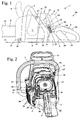
- Fig. 1 schematically shows a chainsaw 1 as an exemplary embodiment of a hand-held implement.
- the hand-held implement may also be another hand-held implement such as a cut-off machine or the like.
- the power saw 1 has a handle unit 2 and a motor unit 16 decoupled from the handle unit 2 via a vibration gap 30 Fig. 1 the motor unit 16 is drawn for clarity with a dashed line and the handle unit 2 with a solid line.
- the handle unit 2 comprises a rear handle 6 and a handle bar 7.
- the handle bracket 7 engages over a housing 4 of the power saw 1.
- the handle unit 2 comprises a fuel tank 3, which is arranged adjacent to the rear handle 6.
- the handle unit 2 also has an extending in the longitudinal direction of the power saw 1 web 5.
- anti-vibration elements 18 and 19 are held.
- two anti-vibration elements 18 and two anti-vibration elements 19 are provided, which are respectively arranged on both sides of the web 5 between the handle unit 2 and the motor unit 16.
- a further anti-vibration element 17 is arranged between a drive motor 11 arranged in the housing 4 and the handle bracket 7.
- the anti-vibration elements 17, 18, 19 may comprise one or more coil springs and / or damping elements made of plastic, for example made of rubber or molded foam.
- the drive motor 11 is part the motor unit 16 and arranged in the embodiment above the web 5.
- the drive motor 11 is an internal combustion engine.
- the drive motor 11 is advantageously a single-cylinder engine, in particular a two-stroke engine or a mixture-lubricated four-stroke engine.
- the drive motor 11 is designed as a rinsing template motor.
- the drive motor 11 has an air channel 15, is sucked via the Spülvorlagen Kunststoff via an air filter 12.
- the drive motor 11 has an intake passage 13 for supplying fuel / air mixture. A portion of the intake passage 13 is formed in a carburetor 14 through which fuel is supplied to the drive motor 11.
- a throttle 21 for operating the drive motor 11 and a throttle lock 22 are pivotally mounted.
- a guide rail 9 forward on which a saw chain 10 is arranged circumferentially.
- the saw chain 10 is driven by the drive motor 11.
- a hand guard 8 At the saw chain 10 facing side of the handle bracket 7 extends a hand guard 8.
- the hand guard 8 may be pivotally mounted on the housing 4 and serve to trigger a braking device, not shown for the saw chain 10.
- the housing 4 has a hood 67 which covers the air filter 12. In the Figures 2 and 3 the hood 67 is removed.
- Another anti-vibration element 20 is fixed adjacent to the fuel tank 3 on the handle unit 2.
- the chainsaw 1 is shown in a parking position 56, in which the chainsaw 1 stands on a flat, horizontal shelf 57.
- the fuel tank 3 has an upper side 58 which faces upwards in the parking position 56.
- the anti-vibration element 20 is fixed to the handle unit 2 with a first end 32 on the upper side 58 of the fuel tank 3. With its second end 33, the anti-vibration element 20 is fixed to the motor unit 16, as will be described in more detail below.
- the anti-vibration member 20 includes a coil spring 31.
- the drive motor 11 has a cylinder 24 to which the anti-vibration element 17 is fixed. To start the drive motor 11 is a not shown, under a fan cover 25 arranged picking device. An Anwerfgriff 23 of the Anwerfvorides protrudes from the housing 4 of the chainsaw 1 addition. As Fig. 2 also shows, the Lspecterradabdeckung 25 has a plurality of cooling air openings 26, is sucked by the cooling air for the drive motor 11 into the housing 4.
- Fig. 2 also shows the arrangement of the anti-vibration element 20 on the upper side 58 of the fuel tank 3 in detail.
- the air filter 12 and the anti-vibration element 20 are visible due to the removed hood 67.
- the coil spring 31 of the anti-vibration element 20 in the longitudinal direction of the power saw 1 that is aligned approximately parallel to the plane of the guide rail 9 and inclined with its second end 33 to the front. In the longitudinal direction of the power saw 1, the second end 33 is thus located in front of the first end 32 of the anti-vibration element 20.
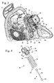
- Fig. 3 shows the arrangement without the coil spring 31 of the anti-vibration element 20.
- Wie Fig. 3 shows, on the upper side 58 of the fuel tank 3, a holding device 51 is arranged, which is designed as a plug with a groove extending on the outer circumference of the plug helically.
- the holding device 51 is held firmly on the fuel tank 3, in particular integrally formed with the fuel tank 3.
- the holding device 51 is arranged adjacent to a ventilation valve 28 arranged on the upper side 58 of the fuel tank 3.
- Fig. 3 is also the filter material 27 of the air filter 12 visible.
- the coil spring 31 of the anti-vibration element 20 is screwed ( Fig. 2 ).
- the helical groove of the holding device 51 forms an external thread.
- the housing 4 adjacent to the Lsymmetricerradabdeckung 25 has a wall 29 on which a fastening web 34 is arranged.
- the fastening web 34 has a mounting opening 35 for a in Fig. 3 not shown retaining element 36 of the anti-vibration element 20.
- the holding member 36 is in Fig. 2 partially visible and in Fig. 4 shown in perspective.
- the attachment opening 35 is a threaded bore.
- the fastening web 34 also has a roof 39 which engages over the retaining element 36, as well as in Fig. 2 is shown.
- the roof 39 forms a stop for the retaining element 36 during assembly.
- Fig. 4 shows the structure of the anti-vibration element 20 without the holding device 51 in detail.
- the holding element 36 has a threaded portion 37 which serves for attachment to the coil spring 31.
- the threaded portion 37 has an external thread 53, which is formed as a helical groove and on which the coil spring 31 is screwed with its second end 33.
- the holding element 36 has a fastening section 38 for attachment to the handle unit 2, namely on the fastening web 34 of the housing 4. Between the threaded section 37 and the fastening section 38, a notch 49 is arranged which forms a predetermined breaking point of the anti-vibration element 20.
- the holding element 36 has a receptacle 41 for the fastening web 34, which is bounded on one side by the fastening section 38 and on the opposite side by a side web 45.
- the side bar 45 has an opening 46, through which a fastening element for the holding element 36 can be mounted.
- the anti-vibration element 20 has a tear-off 42, which includes a safety cable 43.
- the safety rope 43 is advantageously a shear-resistant rope such as a steel cable.
- the safety cable 43 has at each end a fixedly connected to the safety cable 43 nipple 44. In a fraction of the coil spring 31, the holding member 36 is held by the tear-off 42 to the holding device 51, so that handle unit 2 and motor unit 16 via the tear-off 42 together stay.
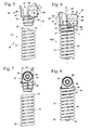
- FIGS. 5 to 8 show the structure of the anti-vibration element 20 without the integrally formed on the fuel tank 3 holding device 51 in detail.
- the threaded portion 37 has an end stop 47th Wie Fig. 8 shows, an end face 48 abuts the second end 33 of the coil spring 31 on the end stop 47 when the coil spring 31 is screwed onto the threaded portion 37, the anti-vibration element 20 is thus mounted.
- the receptacle 41 is approximately U-shaped.
- Notch 49 is located at the bottom of receptacle 41 and extends from the bottom of receptacle 41 in the area between threaded portion 37 and mounting portion 38 Fig.
- the break line 66 is shown with a dashed line.
- the fixing portion 38 and the threaded portion 37 break apart when the anti-vibration element in the direction of its in Fig. 6 shown longitudinal center axis 52 is loaded beyond the forces occurring in normal operation addition.
- the strength of the holding element 36 in the direction of the longitudinal center axis 52 of the anti-vibration element 20 is less than the strength of the holding device 51 in the direction of the longitudinal center axis 52 of the anti-vibration element 20 at the predetermined breaking point, so that the holding element 36 breaks at the predetermined breaking point before the holding device 51 is damaged ,
- the longitudinal central axis 52 corresponds to the longitudinal central axis of the helical spring 31.
- the depth b of the notch 49 is smaller than the width a of the holding member 36 at the break line 66.
- the depth b is advantageously at least 20% of the width a.
- the depth b is at least 40% of the width a.
- the depth b and the width a are measured in the same direction, namely in the longitudinal direction of the break line 66.
- the attachment portion 38 has on the side facing away from the receptacle 41 two pins 50, which simplify the assembly.
- the notch 49 has a first side wall 63 which is formed on the mounting portion 38 and a second side wall 64, which extends adjacent to the threaded portion 37.
- the two side walls 63 and 64 enclose an angle ⁇ , which is significantly smaller than 90 °.
- the angle ⁇ is advantageously less than 45 °. In the exemplary embodiment, the angle ⁇ is approximately 30 °.
- the holding member 36 has on the attachment portion 38 has a width d.
- the width d is greater than the width e of the holding element 36.
- the holding member 36 has a width f, which is significantly greater than the width d and the width e.
- the width e is advantageously less than about 90%, in particular less than about 80% of the width d.
- the width f is advantageously more than about 120%, in particular more than about 150% of the width d.
- the width d, the width e and the width f are measured perpendicular to the longitudinal central axis 52.
- the notch 49 is thus arranged at the narrowest point of the connection between the coil spring 31 and the fastening web 34 ( Fig. 3 ). As Fig. 6 also shows, the longitudinal central axis 52 extends through the notch 49. This results in a good introduction of force in the region of the predetermined breaking point is achieved.
- the side web 45 has a first region 59, which adjoins the threaded portion 37 and a second region 60 which faces away from the threaded portion 37.
- the second region 60 is offset from the first region 59 by an offset c to the outside, that is to say on the side facing away from the attachment section 38.
- the offset c may be, for example, about 50% to about 200% of the depth b of the notch 49.
- the holding member 36 has a threaded opening 40 into which the fastening screw 55 is screwed.
- the perpendicular to the longitudinal central axis 69 of the threaded opening 40 and perpendicular to the longitudinal center axis 52 of the anti-vibration element 20 measured depth g of the holding member 36 is approximately constant from the threaded portion 37 to the longitudinal central axis 69.
- the cross-section of the holding element 36 perpendicular to the longitudinal central axis 52 at the foot 68 of the notch 49 is the lowest.
- the notch 49 extends, as in Fig. 7 is schematically indicated, over the entire depth g of the holding element 36.
- the outer diameter of the opening 46 is significantly larger than the diameter of the threaded opening 40.
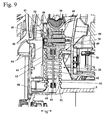
- Wie Fig. 9 shows is the Diameter of the opening 46 is slightly larger than the diameter of the head of the fastening screw 55th
- the fastening web 34 of the housing 4 of the power saw 1 projects into the receptacle 41.
- the fastening screw 55 protrudes through a through hole 54 in the fastening web 34 and is screwed into the threaded opening 40 of the retaining element 36.
- the roof 39 is located on the attachment portion 38 of the support member 36 at.
- the fastening web 34 has a lower edge 70, which engages in the notch 49 and thereby causes a pre-fixing of the retaining element 36 on the fastening web 34 before mounting the fastening screw 55.
- Fig. 9 is also a threaded portion 61 of the holding device 51 visible, in which the coil spring 31 is screwed.
- Fig. 9 is also a threaded portion 61 of the holding device 51 visible, in which the coil spring 31 is screwed.
- a nipple 44 of the tear-off 42 is held in a slot 65 of the holding device 51.
- the second nipple 44 of the tear-off protection 42 is arranged in a receptacle 62 of the holding element 36.
- the nipples 44 each engage behind a section of holding device 51 or holding element 36.
- a double arrow 71 is shown, which illustrates a possible transverse load on the anti-vibration element 20.
- the operator can exert lateral forces on the rear handle 6 when the guide rail 9 is clamped in place (FIG. Fig. 1 ) and thereby move the fuel tank 3 in the direction of the double arrow 71 relative to the fastening web 34.
- transverse forces act on the anti-vibration element 20, which leads to excessive rupture of the connection between the fuel tank 3 and fastening web 34 at the point with the lowest strength, namely at the notch 49.
- the predetermined breaking point is advantageously designed so that the holding element 36 kinks at the notch 49.
- Fig. 9 combined with Fig. 3 shows the foot 68 of the notch 49 ( Fig. 6 ) approximately in the longitudinal direction of the power saw 1.
- the foot 68 is advantageously parallel to the plane of the guide rail 9 (FIG. Fig. 1 ).
Landscapes
- Engineering & Computer Science (AREA)
- Mechanical Engineering (AREA)
- Life Sciences & Earth Sciences (AREA)
- Wood Science & Technology (AREA)
- Forests & Forestry (AREA)
- Portable Power Tools In General (AREA)
- Harvester Elements (AREA)
- Sawing (AREA)
- Vibration Prevention Devices (AREA)
- Handcart (AREA)
Abstract
Ein handgeführtes Arbeitsgerät umfasst eine Motoreinheit (16) mit einem Antriebsmotor (11) sowie eine Griffeinheit (2). Die Griffeinheit (2) ist von der Motoreinheit (16) über mindestens ein Antivibrationselement (17, 18, 19, 20) schwingungsentkoppelt. Das Antivibrationselement (20) ist über eine Halteeinrichtung (51) an einem ersten Bauteil der Griffeinheit (2) und über ein Halteelement (36) an einem zweiten Bauteil der Motoreinheit (16) festgelegt. In der Verbindung des ersten Bauteils mit dem zweiten Bauteil ist eine Sollbruchstelle vorgesehen. Um beim Auftreten übermäßiger Belastungen Beschädigungen weiterer Bauteile des Arbeitsgeräts zu vermeiden, ist vorgesehen, dass die Sollbruchstelle an einem dritten Bauteil ausgebildet ist, das unabhängig von dem ersten Bauteil und dem zweiten Bauteil austauschbar ist, und dass die Verbindung des ersten Bauteils mit dem zweiten Bauteil über das Antivibrationselement an der Sollbruchstelle die geringste Festigkeit aufweist.A hand-held implement comprises a motor unit (16) with a drive motor (11) and a handle unit (2). The handle unit (2) is vibration-decoupled from the motor unit (16) via at least one anti-vibration element (17, 18, 19, 20). The anti-vibration element (20) is fixed to a first component of the handle unit (2) via a retaining device (51) and to a second component of the motor unit (16) via a retaining element (36). In the connection of the first component with the second component, a predetermined breaking point is provided. In order to avoid damage to other components of the working device when excessive loads occur, it is provided that the predetermined breaking point is formed on a third component, which is exchangeable independently of the first component and the second component, and that the connection of the first component with the second component has the least strength over the anti-vibration element at the predetermined breaking point.
Description
Die Erfindung betrifft ein handgeführtes Arbeitsgerät der im Oberbegriff des Anspruchs 1 angegebenen Gattung.The invention relates to a hand-held implement of the type specified in the preamble of
Aus der
Aus der
Der Erfindung liegt die Aufgabe zugrunde, ein handgeführtes Arbeitsgerät der gattungsgemäßen Art zu schaffen, das einen vorteilhaften Aufbau besitzt.The invention has for its object to provide a hand-held implement of the generic type, which has an advantageous structure.
Diese Aufgabe wird durch ein handgeführtes Arbeitsgerät mit den Merkmalen des Anspruchs 1 gelöst.This object is achieved by a hand-held implement with the features of
Das Arbeitsgerät besitzt eine Motoreinheit und eine Griffeinheit, die über mindestens ein Antivibrationselement schwingungsentkoppelt ist. Das Antivibrationselement ist über eine Halteeinrichtung an einem ersten Bauteil der Griffeinheit und über ein Halteelement an einem zweiten Bauteil der Motoreinheit festgelegt. Es ist eine Sollbruchstelle an einem dritten Bauteil vorgesehen, wobei das dritte Bauteil unabhängig von dem ersten und dem zweiten Bauteil austauschbar ist. Die Verbindung des ersten Bauteils mit dem zweiten Bauteil weist dabei an der Sollbruchstelle die geringste Festigkeit auf. Dadurch ist sichergestellt, dass bei einer Überlastung das dritte Bauteil an der Sollbruchstelle bricht. Eine Beschädigung oder Zerstörung des ersten Bauteils oder des zweiten Bauteils, also der Bauteile von Griffeinheit und Motoreinheit, die über das Antivibrationselement miteinander verbunden sind, ist vermieden. Dadurch, dass das dritte Bauteil unabhängig von dem ersten Bauteil und dem zweiten Bauteil austauschbar ist, ist ein einfacher Austausch des dritten Bauteils bei Beschädigung oder Zerstörung möglich. Das erste Bauteil und das zweite Bauteil sind insbesondere Gehäusebauteile von Griffeinheit und Motoreinheit, deren Austausch aufwändig ist und die Demontage weiterer Komponenten des Arbeitsgeräts erfordert. Durch die Anordnung einer definierten Sollbruchstelle an einem dritten, unabhängig von der Griffeinheit und der Motoreinheit austauschbaren Bauteil ist die Reparatur des Arbeitsgeräts vereinfacht.The implement has a motor unit and a handle unit that is vibration decoupled via at least one antivibration element. The anti-vibration element is over a Holding device fixed to a first component of the handle unit and a holding element on a second component of the motor unit. It is provided a predetermined breaking point on a third component, wherein the third component is replaceable independently of the first and the second component. The connection of the first component to the second component has the lowest strength at the predetermined breaking point. This ensures that in case of overloading the third component breaks at the predetermined breaking point. Damage to or destruction of the first component or of the second component, that is to say of the components of the handle unit and motor unit, which are connected to one another via the anti-vibration element, is avoided. Characterized in that the third component is replaceable independently of the first component and the second component, a simple replacement of the third component in case of damage or destruction is possible. The first component and the second component are in particular housing components of handle unit and motor unit, the replacement of which is complicated and requires the disassembly of other components of the implement. The arrangement of a defined predetermined breaking point on a third, independent of the handle unit and the motor unit replaceable component, the repair of the working device is simplified.
Die Festigkeit an der Sollbruchstelle ist vorteilhaft in allen im Betrieb üblicherweise auftretenden Belastungsrichtungen, insbesondere in allen Raumrichtungen geringer als die Festigkeit aller weiteren Bauteile in der Verbindung von erstem und zweitem Bauteil. Auch die Festigkeit des ersten und des zweiten Bauteils ist an der Verbindung mit dem Antivibrationselement höher als die Festigkeit des dritten Bauteils an der Sollbruchstelle. Die im Betrieb üblicherweise auftretenden Belastungsrichtungen sind dabei insbesondere Belastungen quer zur Längsmittelachse des Antivibrationselements, die Scherkräfte auf die Bauteile der Verbindung ausüben, und Belastungen in Richtung der Längsmittelachse des Antivibrationselements, die Zugkräfte auf die Bauteile der Verbindung ausüben.The strength at the predetermined breaking point is advantageously less than the strength of all other components in the connection of the first and second component in all load directions which normally occur during operation, in particular in all spatial directions. The strength of the first and the second component is higher at the connection with the anti-vibration element than the strength of the third component at the predetermined breaking point. The loading directions which normally occur during operation are, in particular, loads transverse to the longitudinal central axis of the anti-vibration element, which exert shear forces on the components of the connection, and loads in the direction of the longitudinal center axis of the anti-vibration element, which exert tensile forces on the components of the connection.
Vorteilhaft ist die Sollbruchstelle des Halteelements durch eine Kerbe gebildet. Über eine Kerbe kann auf einfache Weise eine definierte Sollbruchstelle erzeugt werden. Die Kerbwirkung in der Kerbe stellt sicher, dass das Halteelement an der Sollbruchstelle reißt und nicht in einem anderen Bereich. Der Winkel zwischen den Seitenwänden der Kerbe ist dabei vorteilhaft kleiner als 90°, insbesondere kleiner als 45°. Dadurch wird eine gute Kerbwirkung erreicht. Die Kerbe ist vorteilhaft so angeordnet, dass die Längsmittelachse des Antivibrationselements in unbelastetem Zustand des Antivibrationselements durch die Kerbe verläuft. Dadurch werden Kräfte in Richtung der Längsmittelachse unmittelbar in die Kerbe eingeleitet. Vorteilhaft beträgt die Tiefe der Kerbe mindestens 20% der parallel zur Tiefe der Kerbe gemessenen Breite eines an die Kerbe angrenzenden Abschnitts des dritten Bauteils. Die Tiefe der Kerbe beträgt insbesondere mindestens 40% der parallel zur Tiefe der Kerbe gemessenen Breite des an die Kerbe angrenzenden Abschnitts des dritten Bauteils. Die Breite des an die Kerbe angrenzenden Abschnitts des dritten Bauteils ist dabei die geringste Breite des an die Kerbe angrenzenden Abschnitts des dritten Bauteils und verläuft etwa in Richtung der Bruchlinie, entlang der das dritte Bauteil bricht.Advantageously, the predetermined breaking point of the holding element is formed by a notch. About a notch can be easily generated a defined breaking point. The notch effect in the notch ensures that the holding element tears at the predetermined breaking point and not in another area. The angle between the sidewalls of the notch is while advantageously less than 90 °, in particular less than 45 °. This achieves a good notch effect. The notch is advantageously arranged so that the longitudinal center axis of the anti-vibration element runs in the unloaded state of the anti-vibration element through the notch. As a result, forces are introduced directly into the notch in the direction of the longitudinal central axis. Advantageously, the depth of the notch is at least 20% of the width, measured parallel to the depth of the notch, of a portion of the third component adjacent to the notch. In particular, the depth of the notch is at least 40% of the width of the notch adjacent portion of the third component measured parallel to the depth of the notch. The width of the portion of the third component adjacent to the notch is the smallest width of the portion of the third component adjoining the notch and extends approximately in the direction of the break line along which the third component breaks.
Vorteilhaft ist der Fuß, also der Kerbgrund der Kerbe, etwa in Längsrichtung des Arbeitsgeräts ausgerichtet. Ist das Arbeitsgerät eine Motorsäge mit einer an einer Führungsschiene umlaufend angeordneten Sägekette, so verläuft der Kerbgrund vorteilhaft parallel zur Ebene der Führungsschiene.Advantageously, the foot, so the notch base of the notch, aligned approximately in the longitudinal direction of the implement. If the implement is a chain saw with a saw chain circumferentially arranged on a guide rail, the notch base advantageously runs parallel to the plane of the guide rail.
Das Halteelement ist an der Motoreinheit vorteilhaft lösbar fixiert. Vorteilhaft weist das Halteelement die Sollbruchstelle auf, wobei die Festigkeit des Halteelements an der Sollbruchstelle geringer als die Festigkeit der Halteeinrichtung ist. Das Halteelement bildet das dritte Bauteil. Dadurch, dass das Halteelement, über das das Antivibrationselement an der Motoreinheit festgelegt ist, die Sollbruchstelle aufweist, kann bei einer Überlastung des Antivibrationselements im Betrieb sichergestellt werden, dass das Halteelement an der Motoreinheit an der Sollbruchstelle bricht. Dadurch kann eine Beschädigung der Halteeinrichtung, mit der das Antivibrationselement an der Griffeinheit festgelegt ist, vermieden werden. Ist das Halteelement fest mit der Griffeinheit verbunden, so kann ein Austausch von Teilen der Griffeinheit dadurch vermieden werden. Das Halteelement kann dadurch, dass es an der Motoreinheit lösbar fixiert ist, auf einfache Weise ausgetauscht werden. Dadurch sind Reparaturen einfach möglich. Das dritte Bauteil kann jedoch auch ein anderes Bauteil der Verbindung, beispielsweise ein Befestigungselement des Halteelements sein. Es kann auch vorgesehen sein, dass die Halteeinrichtung lösbar an der Griffeinheit fixiert ist und dass die Halteeinrichtung die Sollbruchstelle aufweist.The holding element is advantageously releasably fixed to the motor unit. Advantageously, the holding element on the predetermined breaking point, wherein the strength of the holding element at the predetermined breaking point is less than the strength of the holding device. The holding element forms the third component. Characterized in that the holding element, via which the anti-vibration element is fixed to the motor unit having the predetermined breaking point, it can be ensured in an overload of the anti-vibration element in operation that the holding element breaks at the motor unit at the predetermined breaking point. As a result, damage to the holding device, with which the anti-vibration element is fixed to the handle unit, can be avoided. If the holding element is firmly connected to the handle unit, an exchange of parts of the handle unit can thereby be avoided. The retaining element can be replaced in a simple manner by being detachably fixed to the motor unit. This makes repairs easy. However, the third component can also be another component of the connection, for example a fastening element of the retaining element. It can also be provided that the holding device is releasably fixed to the handle unit and that the holding device has the predetermined breaking point.
Das Antivibrationselement umfasst vorteilhaft eine Schraubenfeder. Die Längsmittelachse des Antivibrationselements ist vorteilhaft die Längsmittelachse der Schraubenfeder. Vorteilhaft besitzt das Halteelement einen Befestigungsabschnitt zur Befestigung an der Motoreinheit und einen Gewindeabschnitt zur Befestigung an der Schraubenfeder. Die Sollbruchstelle ist vorteilhaft zwischen dem Befestigungsabschnitt und dem Gewindeabschnitt vorgesehen. Dadurch wird die Schraubenfeder bei einem Bruch des Halteelements an der Sollbruchstelle sicher von der Motoreinheit getrennt, so dass über das Antivibrationselement keine Kräfte mehr zwischen Motoreinheit und Griffeinheit übertragen werden können. Dies ist wünschenswert, um die Beschädigung weiterer angrenzender Teile des Arbeitsgeräts, die einen aufwendigen Austausch erfordern, zu verhindern. Ein einfacher Aufbau ergibt sich, wenn der Gewindeabschnitt ein Außengewinde trägt und in die Schraubenfeder eingeschraubt ist. Das Halteelement ist vorteilhaft als in die Schraubenfeder eingeschraubter Stopfen ausgebildet.The anti-vibration element advantageously comprises a helical spring. The longitudinal center axis of the anti-vibration element is advantageously the longitudinal central axis of the helical spring. Advantageously, the retaining element has a mounting portion for attachment to the motor unit and a threaded portion for attachment to the coil spring. The predetermined breaking point is advantageously provided between the fastening portion and the threaded portion. As a result, the coil spring is securely separated from the motor unit at a breakage of the holding element at the predetermined breaking point, so that no forces can be transmitted between the motor unit and the handle unit via the anti-vibration element. This is desirable in order to prevent the damage of other adjacent parts of the implement which require a costly replacement. A simple structure results when the threaded portion carries an external thread and is screwed into the coil spring. The holding element is advantageously formed as screwed into the coil spring plug.
Eine einfache Fixierung des Halteelements wird ermöglicht, wenn das Halteelement eine schlitzförmige Aufnahme besitzt, in die ein Befestigungssteg der Motoreinheit ragt. Dadurch wird eine einfache Positionierung des Halteelements an dem Befestigungssteg der Motoreinheit bei der Montage des Antivibrationselements ermöglicht. Vorteilhaft besitzt der Befestigungssteg ein Dach, das das Halteelement mindestens teilweise übergreift. Das Dach ermöglicht eine Vorpositionierung des Halteelements bei der Montage. Das Dach bildet vorteilhaft einen Anschlag für das Halteelement, so dass das Halteelement bei der Montage einfach mit einer Hand positioniert und mit der anderen Hand befestigt werden kann.A simple fixation of the retaining element is made possible when the retaining element has a slot-shaped receptacle into which a fastening web of the motor unit protrudes. This allows easy positioning of the retaining element on the fastening web of the motor unit during assembly of the anti-vibration element. Advantageously, the fastening web has a roof which at least partially overlaps the retaining element. The roof allows pre-positioning of the retaining element during assembly. The roof advantageously forms a stop for the retaining element, so that the retaining element during assembly can be easily positioned with one hand and secured with the other hand.
Die Aufnahme wird vorteilhaft von dem Befestigungsabschnitt begrenzt, wobei die Kerbe sich von der der Aufnahme zugewandten Seite des Befestigungsabschnitts in das Halteelement erstreckt. Dadurch ergibt sich ein kompakter Aufbau, und Kräfte vom Befestigungssteg können unmittelbar in das Halteelement eingeleitet werden. Die Längsmittelachse des Antivibrationselements ist dabei vorteilhaft in unmittelbarer räumlicher Nähe der Aufnahme angeordnet, so dass sich eine gute Krafteinleitung ergibt.The receptacle is advantageously delimited by the fastening section, wherein the notch extends from the side of the fastening section facing the receptacle into the retaining element. This results in a compact construction, and forces from the fastening web can be introduced directly into the holding element. The longitudinal central axis of the anti-vibration element is advantageously arranged in the immediate vicinity of the recording, so that there is a good application of force.
Vorteilhaft ist die Aufnahme an der dem Befestigungsabschnitt gegenüberliegenden Seite von einem Seitensteg begrenzt. Der Seitensteg weist vorteilhaft eine Öffnung auf, durch die ein Befestigungselement ragt. Der dem Gewindeabschnitt abgewandte Bereich des Seitenstegs ist dabei vorteilhaft gegenüber dem dem Gewindeabschnitt zugewandten Bereich auf die dem Befestigungsabschnitt abgewandte Seite versetzt. Durch die Öffnung im Seitensteg kann das Befestigungselement einfach montiert und festgezogen werden. Der Versatz der beiden Bereiche des Seitenstegs zueinander stellt sicher, dass der dem Gewindeabschnitt abgewandte Bereich des Seitenstegs bei einem Bruch des Halteelements an der Sollbruchstelle nicht an dem Befestigungselement hängen bleiben und dadurch eine Wirkverbindung zwischen Motoreinheit und Griffeinheit herstellen kann. Solange das Befestigungselement noch nicht vollständig montiert ist, kann der Seitensteg am Befestigungselement aufliegen, wodurch die Montage erleichtert wird.Advantageously, the receptacle is bounded on the side opposite the fastening section by a side web. The side bar advantageously has an opening through which a fastening element protrudes. The area of the side web facing away from the threaded portion is advantageously offset from the area facing the threaded portion to the side remote from the mounting portion. Through the opening in the side bar, the fastener can be easily mounted and tightened. The offset of the two regions of the side web to each other ensures that the region of the side web facing away from the threaded portion does not catch on the fastening element at a breakage of the retaining element at the predetermined breaking point and thereby can establish an operative connection between the motor unit and the handle unit. As long as the fastener is not fully assembled, the side bar can rest on the fastener, whereby the assembly is facilitated.
Vorteilhaft umfasst die Halteeinrichtung einen in die Schraubenfeder eingeschraubten Gewindeabschnitt. Das Halteelement weist vorteilhaft eine Aufnahme für eine Abreißsicherung auf. Die Aufnahme für die Abreißsicherung ist dabei vorteilhaft im Gewindeabschnitt des Halteelements vorgesehen. Dadurch ist sichergestellt, dass Motoreinheit und Griffeinheit nach einem Bruch des Halteelements an der Sollbruchstelle auch über die Abreißsicherung nicht weiter verbunden sind.Advantageously, the holding device comprises a screwed into the coil spring threaded portion. The holding element advantageously has a receptacle for a tear-off. The receptacle for the tear-off is advantageously provided in the threaded portion of the support member. This ensures that the motor unit and handle unit are not further connected after a break of the retaining element at the predetermined breaking point on the tear-off.
Vorteilhaft umfasst die Griffeinheit einen Betriebsmitteltank, der das erste Bauteil, an dem das Antivibrationselement festgelegt ist, bildet. Die Halteeinrichtung ist vorteilhaft an dem Betriebsmitteltank ausgebildet. Dadurch, dass die Halteeinrichtung unmittelbar an dem Betriebsmitteltank ausgebildet ist, also kein separates Bauteil ist, ergibt sich ein einfacher Aufbau. Da eine Fixiereinrichtung für die Halteeinrichtung an dem Betriebsmitteltank entfällt, kann der Betriebsmitteltank insgesamt mit geringerer Bauhöhe ausgeführt werden. Durch die Sollbruchstelle am Halteelement kann vermieden werden, dass die Halteeinrichtung am Betriebsmitteltank bei nicht bestimmungsgemäßem Gebrauch des Arbeitsgeräts beschädigt werden kann. Die Sollbruchstelle stellt sicher, dass das Antivibrationselement bei Überlastung am separaten Halteelement und nicht an der Halteeinrichtung am Betriebsmitteltank reißt.Advantageously, the handle unit comprises a resource tank which forms the first component on which the anti-vibration element is fixed. The holding device is advantageously formed on the resource tank. The fact that the holding device is formed directly on the resource tank, so no separate component, there is a simple structure. Since there is no need for a fixing device for the holding device on the operating medium tank, the operating medium tank can be designed overall with a smaller overall height. By the predetermined breaking point on the holding element can be avoided that the holding device on the working fluid tank in improper use of the working device can be damaged. The breaking point ensures that the anti-vibration element ruptures on overload on the separate holding element and not on the holding device on the working fluid tank.
Die Halteeinrichtung ist vorteilhaft an einer in einer Abstellposition des Arbeitsgeräts nach oben weisenden Oberseite des Betriebsmitteltanks angeordnet. Der Betriebsmitteltank ist vorteilhaft benachbart zu einem hinteren Handgriff des Arbeitsgeräts angeordnet. Insbesondere, wenn das Arbeitsgerät eine Motorsäge, ein Trennschleifer oder dgl. mit einem hinteren Handgriff ist, können vom Bediener am Handgriff sehr große Kräfte, insbesondere Querkräfte und/oder Zugkräfte auf ein an der Oberseite des Betriebsmitteltanks angeordnetes Antivibrationselement ausgeübt werden, beispielsweise wenn das Werkzeug im Betrieb einklemmt und das Arbeitsgerät vom Bediener dennoch weiter betrieben wird. Durch die vorgesehene Sollbruchstelle kann eine Beschädigung benachbarter Bauteile bei Überbeanspruchung des Antivibrationselements vermieden werden, da das Halteelement an der Sollbruchstelle bricht, bevor andere Bauteile beschädigt werden können. Die Festigkeit des Halteelements an der Sollbruchstelle ist dabei vorteilhaft größer als die in bestimmungsgemäßem Betrieb auftretenden Kräfte, so dass bei bestimmungsgemäßem Betrieb ein Bruch des Antivibrationselements an der Sollbruchstelle sicher vermieden ist.The holding device is advantageously arranged on a top of the operating fluid tank pointing upwards in a parking position of the working device. The resource tank is advantageously arranged adjacent to a rear handle of the implement. In particular, when the implement is a power saw, a power grinder or the like with a rear handle, the operator can exert very large forces, in particular lateral forces and / or tensile forces, on an anti-vibration element arranged on the top of the operating tank, for example if the tool jammed during operation and the implement is still operated by the operator. By the intended breaking point, damage to adjacent components in case of overuse of the anti-vibration element can be avoided, since the holding element breaks at the predetermined breaking point before other components can be damaged. The strength of the holding element at the predetermined breaking point is advantageously greater than the forces occurring in normal operation, so that when intended operation, a breakage of the anti-vibration element is reliably avoided at the predetermined breaking point.
Ein Ausführungsbeispiel der Erfindung wird im Folgenden anhand der Zeichnung erläutert. Es zeigen:
- Fig. 1
- eine schematische Seitenansicht einer Motorsäge,
- Fig. 2 und Fig. 3
- perspektivische Darstellungen der Motorsäge mit abgenommener Haube,
- Fig. 4
- eine perspektivische Explosionsdarstellung eines Antivibrationselements der Motorsäge,
- Fig. 5
- eine Explosionsdarstellung von Halteelement und Schraubenfeder des Antivibrationselements aus
Fig. 4 in Seitenansicht, - Fig. 6
- eine Seitenansicht von Halteelement, Schraubenfeder und Abreißsicherung des Antivibrationselements,
- Fig. 7
- eine Seitenansicht in Richtung des Pfeils VII in
Fig. 5 , - Fig. 8
- eine Seitenansicht in Richtung des Pfeils VIII in
Fig. 6 , - Fig. 9
- eine vergrößerte Schnittdarstellung durch das Antivibrationselement an der Motorsäge.
- Fig. 1
- a schematic side view of a power saw,
- Fig. 2 and Fig. 3
- perspective views of the power saw with removed hood,
- Fig. 4
- an exploded perspective view of an anti-vibration element of the power saw,
- Fig. 5
- an exploded view of retaining element and coil spring of the anti-vibration element
Fig. 4 in side view, - Fig. 6
- a side view of holding element, coil spring and tear-off of the anti-vibration element,
- Fig. 7
- a side view in the direction of arrow VII in
Fig. 5 . - Fig. 8
- a side view in the direction of arrow VIII in
Fig. 6 . - Fig. 9
- an enlarged sectional view through the anti-vibration element on the chainsaw.
Ein weiteres Antivibrationselement 17 ist zwischen einem im Gehäuse 4 angeordneten Antriebsmotor 11 und dem Griffbügel 7 angeordnet. Die Antivibrationselemente 17, 18, 19 können eine oder mehrere Schraubenfedern und/oder Dämpfungselemente aus Kunststoff, beispielsweise aus Gummi oder aus Formschaum umfassen. Der Antriebsmotor 11 ist Teil der Motoreinheit 16 und im Ausführungsbeispiel oberhalb des Stegs 5 angeordnet. Im Ausführungsbeispiel ist der Antriebsmotor 11 ein Verbrennungsmotor. Vorteilhaft ist der Antriebsmotor 11 ein Einzylindermotor, insbesondere ein Zweitaktmotor oder ein gemischgeschmierter Viertaktmotor. Im Ausführungsbeispiel ist der Antriebsmotor 11 als Spülvorlagenmotor ausgebildet. Der Antriebsmotor 11 besitzt einen Luftkanal 15, über den Spülvorlagenluft über einen Luftfilter 12 angesaugt wird. Außerdem besitzt der Antriebsmotor 11 einen Ansaugkanal 13 zur Zufuhr von Kraftstoff/Luft-Gemisch. Ein Abschnitt des Ansaugkanals 13 ist in einem Vergaser 14 ausgebildet, über den dem Antriebsmotor 11 Kraftstoff zugeführt wird.A
Am hinteren Handgriff 6 sind ein Gashebel 21 zur Bedienung des Antriebsmotors 11 sowie eine Gashebelsperre 22 schwenkbar gelagert. An der dem hinteren Handgriff 6 abgewandten Seite des Gehäuses 4 ragt eine Führungsschiene 9 nach vorn, an der eine Sägekette 10 umlaufend angeordnet ist. Die Sägekette 10 ist von dem Antriebsmotor 11 angetrieben. An der der Sägekette 10 zugewandten Seite des Griffbügels 7 erstreckt sich ein Handschutzbügel 8. Der Handschutzbügel 8 kann am Gehäuse 4 schwenkbar gelagert sein und zum Auslösen einer nicht gezeigten Bremseinrichtung für die Sägekette 10 dienen. Wie
Ein weiteres Antivibrationselement 20 ist benachbart zum Kraftstofftank 3 an der Griffeinheit 2 festgelegt. In
Wie
Wie
Die
Wie
Wie
Wie
Der Seitensteg 45 besitzt einen ersten Bereich 59, der an den Gewindeabschnitt 37 anschließt sowie einen zweiten Bereich 60, der dem Gewindeabschnitt 37 abgewandt liegt. Der zweite Bereich 60 ist gegenüber dem ersten Bereich 59 um einen Versatz c nach außen, also auf die dem Befestigungsabschnitt 38 abgewandte Seite versetzt. Dadurch ist die Aufnahme 41 benachbart zum ersten Bereich 59 oberhalb der Kerbe 49 schmaler als benachbart zum zweiten Bereich 60. Der Versatz c kann beispielsweise etwa 50% bis etwa 200% der Tiefe b der Kerbe 49 betragen.The
Wie
Wie die
Wie
In
Claims (16)
dadurch gekennzeichnet, dass die Sollbruchstelle an einem dritten Bauteil ausgebildet ist, das unabhängig von dem ersten Bauteil und dem zweiten Bauteil austauschbar ist, wobei die Verbindung des ersten Bauteils mit dem zweiten Bauteil über das Antivibrationselement (20) an der Sollbruchstelle die geringste Festigkeit aufweist.Hand-operated implement with a motor unit (16) comprising a drive motor (11), the drive motor (11) driving at least one tool of the implement, and a handle unit (2) comprising at least one handle (6), the handle unit (2) is vibration-decoupled from the motor unit (16) via at least one anti-vibration element (17, 18, 19, 20), wherein the handle unit (2) comprises a first component and the motor unit (16) comprises a second component, wherein the anti-vibration element (20 ) is fixed to the first component via a holding device (51) and to the second component via a holding element (36), and wherein a predetermined breaking point is provided in the connection of the first component to the second component via the anti-vibration element (20),
characterized in that the predetermined breaking point is formed on a third component, which is exchangeable independently of the first component and the second component, wherein the connection of the first component with the second component via the anti-vibration element (20) at the predetermined breaking point has the lowest strength.
dadurch gekennzeichnet, dass die Sollbruchstelle durch eine Kerbe (49) gebildet ist.Working device according to claim 1,
characterized in that the predetermined breaking point is formed by a notch (49).
dadurch gekennzeichnet, dass die Längsmittelachse (52) des Antivibrationselements (20) in unbelastetem Zustand des Antivibrationselements durch die Kerbe (49) verläuft.Working device according to claim 2,
characterized in that the longitudinal center axis (52) of the anti-vibration element (20) extends in the unloaded state of the anti-vibration element through the notch (49).
dadurch gekennzeichnet, dass die Tiefe (b) der Kerbe (49) mindestens 20% der parallel zur Tiefe (b) der Kerbe (49) gemessenen Breite (a) eines an die Kerbe (49) angrenzenden Abschnitts des dritten Bauteils beträgt.Tool according to claim 2 or 3,
characterized in that the depth (b) of the notch (49) is at least 20% of the width (a) measured parallel to the depth (b) of the notch (49) of a portion of the third component adjacent to the notch (49).
dadurch gekennzeichnet, dass das Halteelement (36) an der Motoreinheit (16) lösbar fixiert ist, dass das Halteelement (36) die Sollbruchstelle aufweist, und dass die Festigkeit des Halteelements (36) an der Sollbruchstelle geringer als die Festigkeit der Halteeinrichtung (51) ist.Tool according to one of claims 1 to 4,
characterized in that the holding element (36) on the motor unit (16) is releasably fixed, that the holding element (36) has the predetermined breaking point, and that the strength of the holding element (36) at the predetermined breaking point less than the strength of the holding device (51) is.
dadurch gekennzeichnet, dass das Halteelement (36) einen ersten Befestigungsabschnitt (38) zur Befestigung an der Motoreinheit (16) und einen zweiten Befestigungsabschnitt zur Befestigung an einem Dämpfungselement des Antivibrationselements (20) aufweist, wobei die Sollbruchstelle insbesondere zwischen dem ersten Befestigungsabschnitt (38) und dem zweiten Befestigungsabschnitt vorgesehen ist.Working device according to claim 5,
characterized in that the holding element (36) has a first attachment portion (38) for attachment to the motor unit (16) and a second attachment portion for attachment to a damping element of the anti-vibration element (20), wherein the predetermined breaking point in particular between the first attachment portion (38) and the second attachment portion is provided.
dadurch gekennzeichnet, dass das Antivibrationselement (20) eine Schraubenfeder (31) umfasst und dass die Längsmittelachse (52) des Antivibrationselements (20) die Längsmittelachse der Schraubenfeder (31) ist, wobei der zweite Befestigungsabschnitt insbesondere ein Gewindeabschnitt (37) ist, der ein Außengewinde (53) trägt und der vorteilhaft in die Schraubenfeder (20) eingeschraubt ist.Tool according to one of claims 1 to 6,
characterized in that the anti-vibration element (20) comprises a coil spring (31) and that the longitudinal center axis (52) of the anti-vibration element (20) is the longitudinal center axis of the coil spring (31), wherein the second attachment portion is in particular a threaded portion (37) which External thread (53) carries and is advantageously screwed into the coil spring (20).
dadurch gekennzeichnet, dass das Halteelement (36) eine schlitzförmige Aufnahme (41) besitzt, in die ein Befestigungssteg (34) der Motoreinheit (16) ragt.Tool according to claim 6 or 7,
characterized in that the holding element (36) has a slot-shaped receptacle (41) into which a fastening web (34) of the motor unit (16) protrudes.
dadurch gekennzeichnet, dass der Befestigungssteg (34) ein Dach (39) besitzt, das das Halteelement (36) mindestens teilweise übergreift.Working device according to claim 8,
characterized in that the fastening web (34) has a roof (39) which engages over the retaining element (36) at least partially.
dadurch gekennzeichnet, dass die Aufnahme (41) von dem Befestigungsabschnitt (38) begrenzt wird, wobei die Kerbe (49) sich von der der Aufnahme (41) zugewandten Seite des Befestigungsabschnitts (38) in das Halteelement (36) erstreckt.Tool according to claim 8 or 9,
characterized in that the receptacle (41) of the attachment portion (38) is limited, wherein the notch (49) from the receiving (41) facing side of the mounting portion (38) in the holding element (36).
dadurch gekennzeichnet, dass die Aufnahme (41) an der dem ersten Befestigungsabschnitt (38) gegenüberliegenden Seite von einem Seitensteg (45) begrenzt ist, wobei der Seitensteg (45) eine Öffnung (46) aufweist, durch die ein Befestigungselement ragt, wobei der Seitensteg (45) einen ersten, dem zweiten Befestigungsabschnitt (38) zugewandten Bereich (59) und einen zweiten, dem zweiten Befestigungsabschnitt abgewandten Bereich (60) besitzt, und wobei der zweite Bereich (60) des Seitenstegs (45) gegenüber dem ersten Bereich (59) auf die dem ersten Befestigungsabschnitt (38) abgewandte Seite versetzt ist.Tool according to one of claims 8 to 10,
characterized in that the receptacle (41) is bounded on the side opposite the first fastening section (38) by a side web (45), wherein the side web (45) has an opening (46) through which a fastening element protrudes, wherein the side web (45) has a first area (59) facing the second fastening section (38) and a second area (60) facing away from the second fastening section, and wherein the second area (60) of the side rail (45) is opposite the first area (59 ) is offset on the side facing away from the first attachment portion (38) side.
dadurch gekennzeichnet, dass das Halteelement (36) eine Aufnahme (62) für eine Abreißsicherung (42) aufweist.Tool according to one of claims 4 to 11,
characterized in that the holding element (36) has a receptacle (62) for a tear-off (42).
dadurch gekennzeichnet, dass die Halteeinrichtung (51) einen in die Schraubenfeder (20) eingeschraubten Gewindeabschnitt (61) umfasst.Tool according to one of claims 4 to 12,
characterized in that the holding device (51) comprises a screwed into the coil spring (20) threaded portion (61).
dadurch gekennzeichnet, dass die Griffeinheit (2) einen Betriebsmitteltank umfasst, der das erste Bauteil, an dem das Antivibrationselement (20) festgelegt ist, bildet, und dass die Halteeinrichtung (51) an dem Betriebsmitteltank ausgebildet ist.Tool according to one of claims 4 to 13,
characterized in that the handle unit (2) comprises a resource tank constituting the first member to which the anti-vibration member (20) is fixed, and that the holding means (51) is formed on the equipment tank.
dadurch gekennzeichnet, dass die Halteeinrichtung (51) an einer in einer Abstellposition (56) des Arbeitsgeräts nach oben weisenden Oberseite (58) des Betriebsmitteltanks angeordnet ist.Working device according to claim 14,
characterized in that the holding device (51) is arranged on a in a storage position (56) of the working device upwardly facing top (58) of the resource tank.
dadurch gekennzeichnet, dass der Betriebsmitteltank benachbart zu einem hinteren Handgriff (6) des Arbeitsgeräts angeordnet ist.Tool according to one of claims 13 to 15,
characterized in that the resource tank is disposed adjacent to a rear handle (6) of the implement.
Applications Claiming Priority (1)
| Application Number | Priority Date | Filing Date | Title |
|---|---|---|---|
| DE102013012511.1A DE102013012511A1 (en) | 2013-07-27 | 2013-07-27 | "Hand-guided implement" |
Publications (3)
| Publication Number | Publication Date |
|---|---|
| EP2829363A2 true EP2829363A2 (en) | 2015-01-28 |
| EP2829363A3 EP2829363A3 (en) | 2015-09-23 |
| EP2829363B1 EP2829363B1 (en) | 2017-02-15 |
Family
ID=51224656
Family Applications (1)
| Application Number | Title | Priority Date | Filing Date |
|---|---|---|---|
| EP14002514.9A Active EP2829363B1 (en) | 2013-07-27 | 2014-07-19 | Manually operated work device |
Country Status (6)
| Country | Link |
|---|---|
| US (1) | US9623547B2 (en) |
| EP (1) | EP2829363B1 (en) |
| CN (1) | CN104339421B (en) |
| BR (1) | BR102014018507B1 (en) |
| DE (1) | DE102013012511A1 (en) |
| RU (1) | RU2669958C2 (en) |
Cited By (1)
| Publication number | Priority date | Publication date | Assignee | Title |
|---|---|---|---|---|
| EP3181856A3 (en) * | 2015-12-15 | 2017-07-05 | Andreas Stihl AG & Co. KG | Manually operated working device having a control device |
Families Citing this family (15)
| Publication number | Priority date | Publication date | Assignee | Title |
|---|---|---|---|---|
| US9975235B2 (en) * | 2013-04-05 | 2018-05-22 | John Arthur Notaras | Portable motorised blower with anti-vibration handle system and reduced operating weight |
| DE102013012513A1 (en) | 2013-07-27 | 2015-01-29 | Andreas Stihl Ag & Co. Kg | "Hand-guided implement" |
| EP3094451B1 (en) * | 2014-01-14 | 2023-06-07 | Temple Allen Holdings LLC | Reduced-vibration surface treatment device |
| DE102017011344A1 (en) * | 2017-12-08 | 2019-06-13 | Andreas Stihl Ag & Co. Kg | Arrangement for filling a gas tank |
| EP3599059B1 (en) * | 2018-07-25 | 2022-05-04 | Andreas Stihl AG & Co. KG | Hand-held working device and method for mounting an antivibration element of a hand-held working device |
| CN216442260U (en) | 2019-06-12 | 2022-05-06 | 米沃奇电动工具公司 | electrical tools |
| CN211368546U (en) * | 2019-10-30 | 2020-08-28 | 苏州科瓴精密机械科技有限公司 | Hand-held power tool |
| EP3824714B1 (en) | 2019-11-19 | 2022-10-19 | Andreas Stihl AG & Co. KG | Machining device with a pipe part and a cable arrangement and method of assembly |
| CN112493006A (en) * | 2020-11-27 | 2021-03-16 | 浙江中马园林机器股份有限公司 | Vibration reduction chain saw |
| EP4011197B1 (en) * | 2020-12-11 | 2023-08-30 | Andreas Stihl AG & Co. KG | Working tool with a cable harness between a drive unit and an operating handle |
| EP4169669B1 (en) * | 2021-10-21 | 2024-08-07 | Andreas Stihl AG & Co. KG | Manually operated work device |
| EP4272544B1 (en) * | 2022-05-04 | 2026-04-22 | Andreas Stihl AG & Co. KG | Manually operated work device |
| SE546459C2 (en) * | 2023-02-10 | 2024-11-05 | Husqvarna Ab | Handheld Power Tool Comprising a Fuel Pump Lid Fixating a Fuel Tank and a Handle |
| EP4491340B1 (en) | 2023-07-10 | 2026-03-18 | Andreas Stihl AG & Co. KG | Hand-held work device |
| DE102023118186A1 (en) * | 2023-07-10 | 2025-01-16 | Andreas Stihl Ag & Co. Kg | hand-held tool |
Citations (2)
| Publication number | Priority date | Publication date | Assignee | Title |
|---|---|---|---|---|
| DE10124621A1 (en) | 2001-05-21 | 2002-12-05 | Stihl Maschf Andreas | Resources tank |
| DE102007022115A1 (en) | 2007-05-11 | 2008-11-13 | Andreas Stihl Ag & Co. Kg | Hand-held implement |
Family Cites Families (16)
| Publication number | Priority date | Publication date | Assignee | Title |
|---|---|---|---|---|
| SU1204378A1 (en) * | 1984-06-25 | 1986-01-15 | Сибирский Ордена Трудового Красного Знамени Технологический Институт | Portable method of saw |
| JP2931025B2 (en) | 1989-03-18 | 1999-08-09 | アンドレアス シュティール | Motor-driven hand-held power tool with grips joined by anti-vibration elements |
| JP2598703Y2 (en) | 1992-10-14 | 1999-08-16 | 株式会社共立 | Mounting structure of vibration isolating coil spring |
| JP4081232B2 (en) * | 2000-12-15 | 2008-04-23 | 株式会社共立 | Chainsaw with vibration isolator |
| DE10105826B4 (en) * | 2001-02-07 | 2012-05-31 | Andreas Stihl Ag & Co | Vibration damper between two components |
| US6994068B2 (en) * | 2001-04-28 | 2006-02-07 | Andreas Stihl Ag & Co, Kg | Antivibration device |
| DE10211404B4 (en) * | 2002-03-15 | 2015-02-19 | Andreas Stihl Ag & Co. | Portable, hand-held implement |
| DE20211390U1 (en) | 2002-07-10 | 2003-11-20 | Dolmar GmbH, 22045 Hamburg | Adjustable suspension damping system (anti-vibration system), especially for a hand-held tool |
| US20050138667A1 (en) * | 2003-12-22 | 2005-06-23 | Alain Delpuch | Method and system to control a return path to a source system in an interactive television environment |
| DE10361295B4 (en) * | 2003-12-24 | 2017-11-09 | Andreas Stihl Ag & Co. Kg | Handle tube of a hand-held implement |
| DE102004031866B4 (en) * | 2004-07-01 | 2015-09-10 | Andreas Stihl Ag & Co. Kg | Hand-held implement |
| DE102007048887B4 (en) | 2007-10-11 | 2017-10-26 | Andreas Stihl Ag & Co. Kg | Hand-held implement |
| DE102008064007A1 (en) | 2008-12-19 | 2010-06-24 | Andreas Stihl Ag & Co. Kg | hedge clippers |
| DE102010011986B4 (en) * | 2010-03-19 | 2021-04-01 | Andreas Stihl Ag & Co. Kg | Hand-held tool |
| JP5508097B2 (en) | 2010-03-31 | 2014-05-28 | 株式会社マキタ | Vibration isolator for hand-held work machines |
| DE102013012513A1 (en) | 2013-07-27 | 2015-01-29 | Andreas Stihl Ag & Co. Kg | "Hand-guided implement" |
-
2013
- 2013-07-27 DE DE102013012511.1A patent/DE102013012511A1/en not_active Withdrawn
-
2014
- 2014-07-19 EP EP14002514.9A patent/EP2829363B1/en active Active
- 2014-07-23 RU RU2014130189A patent/RU2669958C2/en active
- 2014-07-25 CN CN201410357145.7A patent/CN104339421B/en active Active
- 2014-07-28 BR BR102014018507-0A patent/BR102014018507B1/en active IP Right Grant
- 2014-07-28 US US14/341,997 patent/US9623547B2/en active Active
Patent Citations (2)
| Publication number | Priority date | Publication date | Assignee | Title |
|---|---|---|---|---|
| DE10124621A1 (en) | 2001-05-21 | 2002-12-05 | Stihl Maschf Andreas | Resources tank |
| DE102007022115A1 (en) | 2007-05-11 | 2008-11-13 | Andreas Stihl Ag & Co. Kg | Hand-held implement |
Cited By (2)
| Publication number | Priority date | Publication date | Assignee | Title |
|---|---|---|---|---|
| EP3181856A3 (en) * | 2015-12-15 | 2017-07-05 | Andreas Stihl AG & Co. KG | Manually operated working device having a control device |
| US10322519B2 (en) | 2015-12-15 | 2019-06-18 | Andreas Stihl Ag & Co. Kg | Hand-guided power tool with a control device |
Also Published As
| Publication number | Publication date |
|---|---|
| RU2669958C2 (en) | 2018-10-17 |
| CN104339421B (en) | 2018-01-19 |
| EP2829363A3 (en) | 2015-09-23 |
| DE102013012511A1 (en) | 2015-01-29 |
| BR102014018507B1 (en) | 2020-10-20 |
| US9623547B2 (en) | 2017-04-18 |
| US20150027745A1 (en) | 2015-01-29 |
| BR102014018507A2 (en) | 2015-09-29 |
| CN104339421A (en) | 2015-02-11 |
| RU2014130189A (en) | 2016-02-20 |
| EP2829363B1 (en) | 2017-02-15 |
Similar Documents
| Publication | Publication Date | Title |
|---|---|---|
| EP2829363B1 (en) | Manually operated work device | |
| DE102006003207B4 (en) | Cover arrangement | |
| DE102007022115B4 (en) | hand-held chainsaw | |
| DE2911498C2 (en) | Portable chainsaw | |
| DE4334924C2 (en) | Fastening device for a vibration-preventing coil spring | |
| DE10105826B4 (en) | Vibration damper between two components | |
| DE10034437B4 (en) | Hand-held implement | |
| DE102010011986B4 (en) | Hand-held tool | |
| DE102010012748A1 (en) | chainsaw | |
| DE4306974A1 (en) | Power-driven sword saw | |
| WO2004039541A1 (en) | Hand-operated machine-tool comprising a vibration-damping rotary handle | |
| DE102004031866B4 (en) | Hand-held implement | |
| EP2974945A1 (en) | Flap for a vehicle | |
| DE60003050T2 (en) | DEVICE AND TO CUT THE REMAINING LENGTH OF A TENSION RING | |
| DE10326472B4 (en) | Connecting element for connecting a handle with a housing part and a transmission housing of a hand-held electrical device | |
| DE10361295B4 (en) | Handle tube of a hand-held implement | |
| DE10128188B4 (en) | Portable work tool | |
| DE102009051561A1 (en) | Fastening element for roof rack of passenger car, has fastening pins pressed into receiving opening of gate section, and projection formed at lower side in area of opening in wall section | |
| WO2016045773A1 (en) | Work device | |
| DE102005036885A1 (en) | Hand-held implement | |
| DE102007012884B4 (en) | Hand-held implement | |
| DE102009033213B4 (en) | Guide rail for the saw chain of a chainsaw | |
| EP4169669B1 (en) | Manually operated work device | |
| DE10393139T5 (en) | Device for a portable working device | |
| DE29910049U1 (en) | Hedge trimmer |
Legal Events
| Date | Code | Title | Description |
|---|---|---|---|
| 17P | Request for examination filed |
Effective date: 20140719 |
|
| AK | Designated contracting states |
Kind code of ref document: A2 Designated state(s): AL AT BE BG CH CY CZ DE DK EE ES FI FR GB GR HR HU IE IS IT LI LT LU LV MC MK MT NL NO PL PT RO RS SE SI SK SM TR |
|
| AX | Request for extension of the european patent |
Extension state: BA ME |
|
| PUAI | Public reference made under article 153(3) epc to a published international application that has entered the european phase |
Free format text: ORIGINAL CODE: 0009012 |
|
| PUAL | Search report despatched |
Free format text: ORIGINAL CODE: 0009013 |
|
| AK | Designated contracting states |
Kind code of ref document: A3 Designated state(s): AL AT BE BG CH CY CZ DE DK EE ES FI FR GB GR HR HU IE IS IT LI LT LU LV MC MK MT NL NO PL PT RO RS SE SI SK SM TR |
|
| AX | Request for extension of the european patent |
Extension state: BA ME |
|
| RIC1 | Information provided on ipc code assigned before grant |
Ipc: B25F 5/00 20060101AFI20150819BHEP |
|
| R17P | Request for examination filed (corrected) |
Effective date: 20151007 |
|
| RBV | Designated contracting states (corrected) |
Designated state(s): AL AT BE BG CH CY CZ DE DK EE ES FI FR GB GR HR HU IE IS IT LI LT LU LV MC MK MT NL NO PL PT RO RS SE SI SK SM TR |
|
| GRAP | Despatch of communication of intention to grant a patent |
Free format text: ORIGINAL CODE: EPIDOSNIGR1 |
|
| INTG | Intention to grant announced |
Effective date: 20160914 |
|
| GRAS | Grant fee paid |
Free format text: ORIGINAL CODE: EPIDOSNIGR3 |
|
| GRAA | (expected) grant |
Free format text: ORIGINAL CODE: 0009210 |
|
| AK | Designated contracting states |
Kind code of ref document: B1 Designated state(s): AL AT BE BG CH CY CZ DE DK EE ES FI FR GB GR HR HU IE IS IT LI LT LU LV MC MK MT NL NO PL PT RO RS SE SI SK SM TR |
|
| REG | Reference to a national code |
Ref country code: CH Ref legal event code: EP Ref country code: GB Ref legal event code: FG4D Free format text: NOT ENGLISH |
|
| REG | Reference to a national code |
Ref country code: IE Ref legal event code: FG4D Free format text: LANGUAGE OF EP DOCUMENT: GERMAN |
|
| REG | Reference to a national code |
Ref country code: AT Ref legal event code: REF Ref document number: 867631 Country of ref document: AT Kind code of ref document: T Effective date: 20170315 |
|
| REG | Reference to a national code |
Ref country code: DE Ref legal event code: R096 Ref document number: 502014002677 Country of ref document: DE |
|
| REG | Reference to a national code |
Ref country code: NL Ref legal event code: MP Effective date: 20170215 |
|
| REG | Reference to a national code |
Ref country code: LT Ref legal event code: MG4D |
|
| REG | Reference to a national code |
Ref country code: FR Ref legal event code: PLFP Year of fee payment: 4 |
|
| PG25 | Lapsed in a contracting state [announced via postgrant information from national office to epo] |
Ref country code: HR Free format text: LAPSE BECAUSE OF FAILURE TO SUBMIT A TRANSLATION OF THE DESCRIPTION OR TO PAY THE FEE WITHIN THE PRESCRIBED TIME-LIMIT Effective date: 20170215 Ref country code: GR Free format text: LAPSE BECAUSE OF FAILURE TO SUBMIT A TRANSLATION OF THE DESCRIPTION OR TO PAY THE FEE WITHIN THE PRESCRIBED TIME-LIMIT Effective date: 20170516 Ref country code: LT Free format text: LAPSE BECAUSE OF FAILURE TO SUBMIT A TRANSLATION OF THE DESCRIPTION OR TO PAY THE FEE WITHIN THE PRESCRIBED TIME-LIMIT Effective date: 20170215 Ref country code: NO Free format text: LAPSE BECAUSE OF FAILURE TO SUBMIT A TRANSLATION OF THE DESCRIPTION OR TO PAY THE FEE WITHIN THE PRESCRIBED TIME-LIMIT Effective date: 20170515 Ref country code: FI Free format text: LAPSE BECAUSE OF FAILURE TO SUBMIT A TRANSLATION OF THE DESCRIPTION OR TO PAY THE FEE WITHIN THE PRESCRIBED TIME-LIMIT Effective date: 20170215 |
|
| PG25 | Lapsed in a contracting state [announced via postgrant information from national office to epo] |
Ref country code: BG Free format text: LAPSE BECAUSE OF FAILURE TO SUBMIT A TRANSLATION OF THE DESCRIPTION OR TO PAY THE FEE WITHIN THE PRESCRIBED TIME-LIMIT Effective date: 20170515 Ref country code: ES Free format text: LAPSE BECAUSE OF FAILURE TO SUBMIT A TRANSLATION OF THE DESCRIPTION OR TO PAY THE FEE WITHIN THE PRESCRIBED TIME-LIMIT Effective date: 20170215 Ref country code: SE Free format text: LAPSE BECAUSE OF FAILURE TO SUBMIT A TRANSLATION OF THE DESCRIPTION OR TO PAY THE FEE WITHIN THE PRESCRIBED TIME-LIMIT Effective date: 20170215 Ref country code: RS Free format text: LAPSE BECAUSE OF FAILURE TO SUBMIT A TRANSLATION OF THE DESCRIPTION OR TO PAY THE FEE WITHIN THE PRESCRIBED TIME-LIMIT Effective date: 20170215 Ref country code: NL Free format text: LAPSE BECAUSE OF FAILURE TO SUBMIT A TRANSLATION OF THE DESCRIPTION OR TO PAY THE FEE WITHIN THE PRESCRIBED TIME-LIMIT Effective date: 20170215 Ref country code: LV Free format text: LAPSE BECAUSE OF FAILURE TO SUBMIT A TRANSLATION OF THE DESCRIPTION OR TO PAY THE FEE WITHIN THE PRESCRIBED TIME-LIMIT Effective date: 20170215 Ref country code: PT Free format text: LAPSE BECAUSE OF FAILURE TO SUBMIT A TRANSLATION OF THE DESCRIPTION OR TO PAY THE FEE WITHIN THE PRESCRIBED TIME-LIMIT Effective date: 20170615 |
|
| PG25 | Lapsed in a contracting state [announced via postgrant information from national office to epo] |
Ref country code: CZ Free format text: LAPSE BECAUSE OF FAILURE TO SUBMIT A TRANSLATION OF THE DESCRIPTION OR TO PAY THE FEE WITHIN THE PRESCRIBED TIME-LIMIT Effective date: 20170215 Ref country code: RO Free format text: LAPSE BECAUSE OF FAILURE TO SUBMIT A TRANSLATION OF THE DESCRIPTION OR TO PAY THE FEE WITHIN THE PRESCRIBED TIME-LIMIT Effective date: 20170215 Ref country code: EE Free format text: LAPSE BECAUSE OF FAILURE TO SUBMIT A TRANSLATION OF THE DESCRIPTION OR TO PAY THE FEE WITHIN THE PRESCRIBED TIME-LIMIT Effective date: 20170215 Ref country code: SK Free format text: LAPSE BECAUSE OF FAILURE TO SUBMIT A TRANSLATION OF THE DESCRIPTION OR TO PAY THE FEE WITHIN THE PRESCRIBED TIME-LIMIT Effective date: 20170215 Ref country code: IT Free format text: LAPSE BECAUSE OF FAILURE TO SUBMIT A TRANSLATION OF THE DESCRIPTION OR TO PAY THE FEE WITHIN THE PRESCRIBED TIME-LIMIT Effective date: 20170215 |
|
| REG | Reference to a national code |
Ref country code: DE Ref legal event code: R097 Ref document number: 502014002677 Country of ref document: DE |
|
| PG25 | Lapsed in a contracting state [announced via postgrant information from national office to epo] |
Ref country code: SM Free format text: LAPSE BECAUSE OF FAILURE TO SUBMIT A TRANSLATION OF THE DESCRIPTION OR TO PAY THE FEE WITHIN THE PRESCRIBED TIME-LIMIT Effective date: 20170215 Ref country code: DK Free format text: LAPSE BECAUSE OF FAILURE TO SUBMIT A TRANSLATION OF THE DESCRIPTION OR TO PAY THE FEE WITHIN THE PRESCRIBED TIME-LIMIT Effective date: 20170215 Ref country code: PL Free format text: LAPSE BECAUSE OF FAILURE TO SUBMIT A TRANSLATION OF THE DESCRIPTION OR TO PAY THE FEE WITHIN THE PRESCRIBED TIME-LIMIT Effective date: 20170215 |
|
| PLBE | No opposition filed within time limit |
Free format text: ORIGINAL CODE: 0009261 |
|
| STAA | Information on the status of an ep patent application or granted ep patent |
Free format text: STATUS: NO OPPOSITION FILED WITHIN TIME LIMIT |
|
| 26N | No opposition filed |
Effective date: 20171116 |
|
| PG25 | Lapsed in a contracting state [announced via postgrant information from national office to epo] |
Ref country code: SI Free format text: LAPSE BECAUSE OF FAILURE TO SUBMIT A TRANSLATION OF THE DESCRIPTION OR TO PAY THE FEE WITHIN THE PRESCRIBED TIME-LIMIT Effective date: 20170215 |
|
| REG | Reference to a national code |
Ref country code: CH Ref legal event code: PL |
|
| REG | Reference to a national code |
Ref country code: IE Ref legal event code: MM4A |
|
| PG25 | Lapsed in a contracting state [announced via postgrant information from national office to epo] |
Ref country code: CH Free format text: LAPSE BECAUSE OF NON-PAYMENT OF DUE FEES Effective date: 20170731 Ref country code: LI Free format text: LAPSE BECAUSE OF NON-PAYMENT OF DUE FEES Effective date: 20170731 Ref country code: IE Free format text: LAPSE BECAUSE OF NON-PAYMENT OF DUE FEES Effective date: 20170719 |
|
| REG | Reference to a national code |
Ref country code: BE Ref legal event code: MM Effective date: 20170731 |
|
| PG25 | Lapsed in a contracting state [announced via postgrant information from national office to epo] |
Ref country code: LU Free format text: LAPSE BECAUSE OF NON-PAYMENT OF DUE FEES Effective date: 20170719 |
|
| REG | Reference to a national code |
Ref country code: FR Ref legal event code: PLFP Year of fee payment: 5 |
|
| PG25 | Lapsed in a contracting state [announced via postgrant information from national office to epo] |
Ref country code: BE Free format text: LAPSE BECAUSE OF NON-PAYMENT OF DUE FEES Effective date: 20170731 |
|
| PG25 | Lapsed in a contracting state [announced via postgrant information from national office to epo] |
Ref country code: MT Free format text: LAPSE BECAUSE OF FAILURE TO SUBMIT A TRANSLATION OF THE DESCRIPTION OR TO PAY THE FEE WITHIN THE PRESCRIBED TIME-LIMIT Effective date: 20170215 |
|
| PG25 | Lapsed in a contracting state [announced via postgrant information from national office to epo] |
Ref country code: HU Free format text: LAPSE BECAUSE OF FAILURE TO SUBMIT A TRANSLATION OF THE DESCRIPTION OR TO PAY THE FEE WITHIN THE PRESCRIBED TIME-LIMIT; INVALID AB INITIO Effective date: 20140719 Ref country code: MC Free format text: LAPSE BECAUSE OF FAILURE TO SUBMIT A TRANSLATION OF THE DESCRIPTION OR TO PAY THE FEE WITHIN THE PRESCRIBED TIME-LIMIT Effective date: 20170215 |
|
| PG25 | Lapsed in a contracting state [announced via postgrant information from national office to epo] |
Ref country code: CY Free format text: LAPSE BECAUSE OF FAILURE TO SUBMIT A TRANSLATION OF THE DESCRIPTION OR TO PAY THE FEE WITHIN THE PRESCRIBED TIME-LIMIT Effective date: 20170215 |
|
| PG25 | Lapsed in a contracting state [announced via postgrant information from national office to epo] |
Ref country code: MK Free format text: LAPSE BECAUSE OF FAILURE TO SUBMIT A TRANSLATION OF THE DESCRIPTION OR TO PAY THE FEE WITHIN THE PRESCRIBED TIME-LIMIT Effective date: 20170215 |
|
| PG25 | Lapsed in a contracting state [announced via postgrant information from national office to epo] |
Ref country code: TR Free format text: LAPSE BECAUSE OF FAILURE TO SUBMIT A TRANSLATION OF THE DESCRIPTION OR TO PAY THE FEE WITHIN THE PRESCRIBED TIME-LIMIT Effective date: 20170215 |
|
| PG25 | Lapsed in a contracting state [announced via postgrant information from national office to epo] |
Ref country code: AL Free format text: LAPSE BECAUSE OF FAILURE TO SUBMIT A TRANSLATION OF THE DESCRIPTION OR TO PAY THE FEE WITHIN THE PRESCRIBED TIME-LIMIT Effective date: 20170215 Ref country code: IS Free format text: LAPSE BECAUSE OF FAILURE TO SUBMIT A TRANSLATION OF THE DESCRIPTION OR TO PAY THE FEE WITHIN THE PRESCRIBED TIME-LIMIT Effective date: 20170615 |
|
| REG | Reference to a national code |
Ref country code: AT Ref legal event code: MM01 Ref document number: 867631 Country of ref document: AT Kind code of ref document: T Effective date: 20190719 |
|
| PG25 | Lapsed in a contracting state [announced via postgrant information from national office to epo] |
Ref country code: AT Free format text: LAPSE BECAUSE OF NON-PAYMENT OF DUE FEES Effective date: 20190719 |
|
| PGFP | Annual fee paid to national office [announced via postgrant information from national office to epo] |
Ref country code: DE Payment date: 20250728 Year of fee payment: 12 |
|
| PGFP | Annual fee paid to national office [announced via postgrant information from national office to epo] |
Ref country code: GB Payment date: 20250722 Year of fee payment: 12 |
|
| PGFP | Annual fee paid to national office [announced via postgrant information from national office to epo] |
Ref country code: FR Payment date: 20250725 Year of fee payment: 12 |