EP2829485A1 - Casier à bouteilles avec insert en treillis réglable en hauteur - Google Patents
Casier à bouteilles avec insert en treillis réglable en hauteur Download PDFInfo
- Publication number
- EP2829485A1 EP2829485A1 EP13177716.1A EP13177716A EP2829485A1 EP 2829485 A1 EP2829485 A1 EP 2829485A1 EP 13177716 A EP13177716 A EP 13177716A EP 2829485 A1 EP2829485 A1 EP 2829485A1
- Authority
- EP
- European Patent Office
- Prior art keywords
- truss
- bottle crate
- bottle
- insert
- guide
- Prior art date
- Legal status (The legal status is an assumption and is not a legal conclusion. Google has not performed a legal analysis and makes no representation as to the accuracy of the status listed.)
- Granted
Links
- 238000003780 insertion Methods 0.000 claims description 14
- 230000037431 insertion Effects 0.000 claims description 14
- 230000000295 complement effect Effects 0.000 claims description 4
- 230000002093 peripheral effect Effects 0.000 claims description 3
- 239000000463 material Substances 0.000 claims description 2
- 235000013361 beverage Nutrition 0.000 description 7
- 230000003993 interaction Effects 0.000 description 7
- 238000013461 design Methods 0.000 description 3
- 238000004519 manufacturing process Methods 0.000 description 3
- 238000004140 cleaning Methods 0.000 description 2
- 239000002131 composite material Substances 0.000 description 2
- 230000005484 gravity Effects 0.000 description 2
- 238000001746 injection moulding Methods 0.000 description 2
- 238000005192 partition Methods 0.000 description 2
- 210000002105 tongue Anatomy 0.000 description 2
- 240000001439 Opuntia Species 0.000 description 1
- 235000004727 Opuntia ficus indica Nutrition 0.000 description 1
- 230000000712 assembly Effects 0.000 description 1
- 238000000429 assembly Methods 0.000 description 1
- 230000001419 dependent effect Effects 0.000 description 1
- 238000011161 development Methods 0.000 description 1
- 230000018109 developmental process Effects 0.000 description 1
- 238000005516 engineering process Methods 0.000 description 1
- 238000012986 modification Methods 0.000 description 1
- 230000004048 modification Effects 0.000 description 1
- 238000004806 packaging method and process Methods 0.000 description 1
- 230000036316 preload Effects 0.000 description 1
- 230000000630 rising effect Effects 0.000 description 1
- 238000000926 separation method Methods 0.000 description 1
Images


Classifications
-
- B—PERFORMING OPERATIONS; TRANSPORTING
- B65—CONVEYING; PACKING; STORING; HANDLING THIN OR FILAMENTARY MATERIAL
- B65D—CONTAINERS FOR STORAGE OR TRANSPORT OF ARTICLES OR MATERIALS, e.g. BAGS, BARRELS, BOTTLES, BOXES, CANS, CARTONS, CRATES, DRUMS, JARS, TANKS, HOPPERS, FORWARDING CONTAINERS; ACCESSORIES, CLOSURES, OR FITTINGS THEREFOR; PACKAGING ELEMENTS; PACKAGES
- B65D1/00—Rigid or semi-rigid containers having bodies formed in one piece, e.g. by casting metallic material, by moulding plastics, by blowing vitreous material, by throwing ceramic material, by moulding pulped fibrous material or by deep-drawing operations performed on sheet material
- B65D1/22—Boxes or like containers with side walls of substantial depth for enclosing contents
- B65D1/24—Boxes or like containers with side walls of substantial depth for enclosing contents with moulded compartments or partitions
- B65D1/243—Crates for bottles or like containers
-
- B—PERFORMING OPERATIONS; TRANSPORTING
- B65—CONVEYING; PACKING; STORING; HANDLING THIN OR FILAMENTARY MATERIAL
- B65D—CONTAINERS FOR STORAGE OR TRANSPORT OF ARTICLES OR MATERIALS, e.g. BAGS, BARRELS, BOTTLES, BOXES, CANS, CARTONS, CRATES, DRUMS, JARS, TANKS, HOPPERS, FORWARDING CONTAINERS; ACCESSORIES, CLOSURES, OR FITTINGS THEREFOR; PACKAGING ELEMENTS; PACKAGES
- B65D25/00—Details of other kinds or types of rigid or semi-rigid containers
- B65D25/02—Internal fittings
- B65D25/10—Devices to locate articles in containers
-
- B—PERFORMING OPERATIONS; TRANSPORTING
- B65—CONVEYING; PACKING; STORING; HANDLING THIN OR FILAMENTARY MATERIAL
- B65D—CONTAINERS FOR STORAGE OR TRANSPORT OF ARTICLES OR MATERIALS, e.g. BAGS, BARRELS, BOTTLES, BOXES, CANS, CARTONS, CRATES, DRUMS, JARS, TANKS, HOPPERS, FORWARDING CONTAINERS; ACCESSORIES, CLOSURES, OR FITTINGS THEREFOR; PACKAGING ELEMENTS; PACKAGES
- B65D2501/00—Containers having bodies formed in one piece
- B65D2501/24—Boxes or like containers with moulded compartments or partitions
- B65D2501/24006—Details relating to bottle crates
- B65D2501/24012—Materials
- B65D2501/24019—Mainly plastics
-
- B—PERFORMING OPERATIONS; TRANSPORTING
- B65—CONVEYING; PACKING; STORING; HANDLING THIN OR FILAMENTARY MATERIAL
- B65D—CONTAINERS FOR STORAGE OR TRANSPORT OF ARTICLES OR MATERIALS, e.g. BAGS, BARRELS, BOTTLES, BOXES, CANS, CARTONS, CRATES, DRUMS, JARS, TANKS, HOPPERS, FORWARDING CONTAINERS; ACCESSORIES, CLOSURES, OR FITTINGS THEREFOR; PACKAGING ELEMENTS; PACKAGES
- B65D2501/00—Containers having bodies formed in one piece
- B65D2501/24—Boxes or like containers with moulded compartments or partitions
- B65D2501/24006—Details relating to bottle crates
- B65D2501/2405—Construction
- B65D2501/24063—Construction of the walls
- B65D2501/2407—Apertured
-
- B—PERFORMING OPERATIONS; TRANSPORTING
- B65—CONVEYING; PACKING; STORING; HANDLING THIN OR FILAMENTARY MATERIAL
- B65D—CONTAINERS FOR STORAGE OR TRANSPORT OF ARTICLES OR MATERIALS, e.g. BAGS, BARRELS, BOTTLES, BOXES, CANS, CARTONS, CRATES, DRUMS, JARS, TANKS, HOPPERS, FORWARDING CONTAINERS; ACCESSORIES, CLOSURES, OR FITTINGS THEREFOR; PACKAGING ELEMENTS; PACKAGES
- B65D2501/00—Containers having bodies formed in one piece
- B65D2501/24—Boxes or like containers with moulded compartments or partitions
- B65D2501/24006—Details relating to bottle crates
- B65D2501/2405—Construction
- B65D2501/24121—Construction of the bottom
- B65D2501/24133—Grid, mesh
-
- B—PERFORMING OPERATIONS; TRANSPORTING
- B65—CONVEYING; PACKING; STORING; HANDLING THIN OR FILAMENTARY MATERIAL
- B65D—CONTAINERS FOR STORAGE OR TRANSPORT OF ARTICLES OR MATERIALS, e.g. BAGS, BARRELS, BOTTLES, BOXES, CANS, CARTONS, CRATES, DRUMS, JARS, TANKS, HOPPERS, FORWARDING CONTAINERS; ACCESSORIES, CLOSURES, OR FITTINGS THEREFOR; PACKAGING ELEMENTS; PACKAGES
- B65D2501/00—Containers having bodies formed in one piece
- B65D2501/24—Boxes or like containers with moulded compartments or partitions
- B65D2501/24006—Details relating to bottle crates
- B65D2501/2405—Construction
- B65D2501/24146—Connection between walls or of walls with bottom
- B65D2501/24152—Integral
-
- B—PERFORMING OPERATIONS; TRANSPORTING
- B65—CONVEYING; PACKING; STORING; HANDLING THIN OR FILAMENTARY MATERIAL
- B65D—CONTAINERS FOR STORAGE OR TRANSPORT OF ARTICLES OR MATERIALS, e.g. BAGS, BARRELS, BOTTLES, BOXES, CANS, CARTONS, CRATES, DRUMS, JARS, TANKS, HOPPERS, FORWARDING CONTAINERS; ACCESSORIES, CLOSURES, OR FITTINGS THEREFOR; PACKAGING ELEMENTS; PACKAGES
- B65D2501/00—Containers having bodies formed in one piece
- B65D2501/24—Boxes or like containers with moulded compartments or partitions
- B65D2501/24006—Details relating to bottle crates
- B65D2501/24197—Arrangements for locating the bottles
- B65D2501/24203—Construction of locating arrangements
- B65D2501/2421—Partitions
- B65D2501/24216—Partitions forming square or rectangular cells
-
- B—PERFORMING OPERATIONS; TRANSPORTING
- B65—CONVEYING; PACKING; STORING; HANDLING THIN OR FILAMENTARY MATERIAL
- B65D—CONTAINERS FOR STORAGE OR TRANSPORT OF ARTICLES OR MATERIALS, e.g. BAGS, BARRELS, BOTTLES, BOXES, CANS, CARTONS, CRATES, DRUMS, JARS, TANKS, HOPPERS, FORWARDING CONTAINERS; ACCESSORIES, CLOSURES, OR FITTINGS THEREFOR; PACKAGING ELEMENTS; PACKAGES
- B65D2501/00—Containers having bodies formed in one piece
- B65D2501/24—Boxes or like containers with moulded compartments or partitions
- B65D2501/24006—Details relating to bottle crates
- B65D2501/24197—Arrangements for locating the bottles
- B65D2501/24203—Construction of locating arrangements
- B65D2501/2421—Partitions
- B65D2501/24222—Partitions forming cells having a curved shape
-
- B—PERFORMING OPERATIONS; TRANSPORTING
- B65—CONVEYING; PACKING; STORING; HANDLING THIN OR FILAMENTARY MATERIAL
- B65D—CONTAINERS FOR STORAGE OR TRANSPORT OF ARTICLES OR MATERIALS, e.g. BAGS, BARRELS, BOTTLES, BOXES, CANS, CARTONS, CRATES, DRUMS, JARS, TANKS, HOPPERS, FORWARDING CONTAINERS; ACCESSORIES, CLOSURES, OR FITTINGS THEREFOR; PACKAGING ELEMENTS; PACKAGES
- B65D2501/00—Containers having bodies formed in one piece
- B65D2501/24—Boxes or like containers with moulded compartments or partitions
- B65D2501/24006—Details relating to bottle crates
- B65D2501/24197—Arrangements for locating the bottles
- B65D2501/24203—Construction of locating arrangements
- B65D2501/24286—Adjustable or removable constructions
-
- B—PERFORMING OPERATIONS; TRANSPORTING
- B65—CONVEYING; PACKING; STORING; HANDLING THIN OR FILAMENTARY MATERIAL
- B65D—CONTAINERS FOR STORAGE OR TRANSPORT OF ARTICLES OR MATERIALS, e.g. BAGS, BARRELS, BOTTLES, BOXES, CANS, CARTONS, CRATES, DRUMS, JARS, TANKS, HOPPERS, FORWARDING CONTAINERS; ACCESSORIES, CLOSURES, OR FITTINGS THEREFOR; PACKAGING ELEMENTS; PACKAGES
- B65D2501/00—Containers having bodies formed in one piece
- B65D2501/24—Boxes or like containers with moulded compartments or partitions
- B65D2501/24006—Details relating to bottle crates
- B65D2501/24197—Arrangements for locating the bottles
- B65D2501/24337—Means for accommodating bottles of different sizes
-
- B—PERFORMING OPERATIONS; TRANSPORTING
- B65—CONVEYING; PACKING; STORING; HANDLING THIN OR FILAMENTARY MATERIAL
- B65D—CONTAINERS FOR STORAGE OR TRANSPORT OF ARTICLES OR MATERIALS, e.g. BAGS, BARRELS, BOTTLES, BOXES, CANS, CARTONS, CRATES, DRUMS, JARS, TANKS, HOPPERS, FORWARDING CONTAINERS; ACCESSORIES, CLOSURES, OR FITTINGS THEREFOR; PACKAGING ELEMENTS; PACKAGES
- B65D2501/00—Containers having bodies formed in one piece
- B65D2501/24—Boxes or like containers with moulded compartments or partitions
- B65D2501/24006—Details relating to bottle crates
- B65D2501/24363—Handles
- B65D2501/24541—Hand holes
-
- B—PERFORMING OPERATIONS; TRANSPORTING
- B65—CONVEYING; PACKING; STORING; HANDLING THIN OR FILAMENTARY MATERIAL
- B65D—CONTAINERS FOR STORAGE OR TRANSPORT OF ARTICLES OR MATERIALS, e.g. BAGS, BARRELS, BOTTLES, BOXES, CANS, CARTONS, CRATES, DRUMS, JARS, TANKS, HOPPERS, FORWARDING CONTAINERS; ACCESSORIES, CLOSURES, OR FITTINGS THEREFOR; PACKAGING ELEMENTS; PACKAGES
- B65D2501/00—Containers having bodies formed in one piece
- B65D2501/24—Boxes or like containers with moulded compartments or partitions
- B65D2501/24006—Details relating to bottle crates
- B65D2501/24554—Stacking means
- B65D2501/24585—Stacking means for stacking or joining the crates together one upon the other, in the upright or upside-down position
- B65D2501/24598—Crates presenting a continuous stacking profile along the upper edge of at least two opposite side walls
Definitions
- the present invention relates to a bottle crate with a truss insert according to the preamble of claim 1.
- Simple bottle crate inserts or truss inserts for insertion into the interior of a bottle crate are z. B. off US 2,119,889 A . DE 17 48 170 U . DE 18 39 065 U or GB 873 288 A known. These inserts usually consist of a truss with longitudinal and transverse webs, which define compartments for receiving bottles. Due to advances in manufacturing technology and the ability to produce bottle cases together with truss in one piece in an injection molding process, one has moved away from the use of separate bottle crate inserts in recent decades. However, bottle crate inserts have the advantage that only by replacing the insert of the bottle crate can be adapted to different bottle sizes, eg. B. 24 x 0.3 I, 30 x 0.25 I, 12 x 1 I, 10 x 1.5 I or 8 x 2.5 I bottles, such as. In EP 0 655 397 A1 or EP 1 637 470 A1 is shown.
- Object of the present invention is to provide a comparison with the prior art improved and more user-friendly bottle crate with a truss insert, which is equally suitable for transporting a bottle or can composite and other objects as well as for the transport of individual bottles or cans.
- An inventive bottle crate has a removable truss insert for receiving bottles or cans.
- removable or a “removability” is understood here as opposed to “removable” or a “disassembly” a suitability in terms of a geometric configuration for preferably tool-free removal.
- the guides of bottle crate and truss work cooperate such that the used in a first orientation truss insert via at least a first pair of guides (or on the interaction of this first pair of guides) to the bottle case bottom can be lowered and lowered in a first orientation to the first orientation or turned second orientation on at least one second pair of guides (or on the interaction of this second pair of guides) only until at least one of the bottle crate floor spaced predetermined height or height position is lowered.
- the truss can be lowered either to the ground, so that it rests on the bottle case bottom or at least in this vicinity, or in a position or height in which it is spaced from the ground , to be brought.
- the bottle crate according to the invention thus has a height-adjustable truss insert which, depending on its orientation, can be brought into two different height positions and remain in them due to gravity.
- the half-timbered insert serves as an ordinary bottle crate for receiving and lateral support or separation of bottles or cans placed in the bottle crate. Since the truss is height adjustable, the management level of the truss use can be changed.
- beverage crates made from several bottles or cans wrapped in cardboard can be placed on the lowered truss with the bottle crate can be placed and thus can be completely absorbed in the bottle crate.
- beverage crates made from several bottles or cans wrapped in cardboard can be placed on the lowered truss with the bottle crate can be placed and thus can be completely absorbed in the bottle crate.
- the cardboard was removed from the beverage associations and the bottles or cans were emptied, they can also be transported as individual bottles or cans safely with the bottle case according to the invention, as taken in the bottle case of the invention, the truss used, oriented differently and placed in a spaced position from the bottom of the bottle can be, in which the individual bottles or cans are laterally supported by the truss.
- the bottle case according to the invention can accommodate a variety of individual bottles or cans and separate from each other, so that the bottles or cans do not hit each other during transport and probably go to breakage.
- the truss insert may be a grid or plate-shaped insert having a plurality of openings, apertures or bottle nests into which bottles or cans may be placed separately.
- the truss can be sized in thickness or height so that on the one hand not much space consumed when it is lowered to the bottom of the bottle, on the other hand sufficient vertical guide surfaces or sections to tilt or jamming of the truss insert when lifting or lowering the bottle crate to avoid.
- the half-timbered insert can be aligned differently by turning or turning and, depending on the orientation, lowered to different depths in the bottle crate.
- the half-timbered insert must be rotated either by 180 ° about a vertical axis (height axis) or a horizontal axis (transverse axis).
- This principle at least as far as the rotation about the vertical axis is concerned, is known in a similar form from rotary stacking containers, whereby it does not matter here to be able to nest the container at different heights within the other container.
- the bottle crate according to the invention allows for a replacement of the truss use depending on the transported bottle or can sizes and beyond also the ability to safely transport the respective bottle or can sizes in the beverage network and as single bottles.
- the interchangeability of the truss use also has the advantage that in case of damage to the truss not the entire bottle crate, but only the truss can be replaced, which costs can be saved. Furthermore, the bottle crate and truss as a separate parts are easier to manufacture than an integrated component.
- the first guide pair which allows the lowering to the bottle case bottom
- the second guide pair which allows the lowering only up to a predetermined height
- the inner profile of the bottle crate and / or the outer profile of the truss insert can thus be designed asymmetrically. Due to the asymmetry of the guide pairings, different pairs of guides act together, depending on the orientation of the truss insert. Thus, it is not necessary to make any changes to the bottle crate or truss used to allow the height adjustment of the truss insert. This height adjustment is based solely on the rotation or turn of the same truss use.
- the first guide pair may be formed by a first truss-side guide element and a first box-side guide element extending to the bottle case bottom.
- the second guide pair can be formed by the first or a second framework-side guide element and a second box-side guide element reaching only up to the predetermined height position.
- the truss and box side guide elements not only allow vertical guidance of the truss insert when raising or lowering, but also limit the degree of freedom of the truss insert in the bottle crate.
- the height limit can be realized solely by the design of the box-side guide elements.
- the first truss-side guide element has a guide pin or guide projection formed on a peripheral or outer side of the truss insert or on an inner side or inner surface of a quill receptacle of the truss insert.
- the box-side guide elements can be designed correspondingly in shape and position complementary to the bottle crate.
- the first box-side guide element may have a first box-side guide groove formed on a side inner wall or quill of the bottle crate and extending to the bottle case bottom.
- the second box-side guide element may have a formed on a side inner wall or quill of the bottle crate and only reaching to the predetermined height position second guide groove.
- the truss-side guide pin or projection cooperates with or engages the box-side first guide groove and, in the second alignment of the trussed insert, the truss-side guide pin or projection interacts with or engages with the box-side second guide groove one.
- guide pins or projections may be formed on the box side and the corresponding guide grooves formed lattice-side, if it is ensured that the truss can be placed in different height positions depending on its orientation.
- Such guide pins or protrusions or guide grooves are easy to produce in terms of production, so that a versatile bottle crate can be provided with little effort.
- the first and / or second guide groove does not extend to the upper edge of the bottle crate.
- the guide grooves do not run upwards but are closed. This can ensure that the truss does not slip out of the guides or the bottle crate, if this z. B. is made for cleaning purposes upside down. To remove the truss insert this must only be tilted slightly, so that the corresponding guide elements are released.
- the truss used on a first side of a flat support surface and on an opposite side formed between the receiving openings or bottle nests insertion bevels.
- the insertion slopes facing up and the flat bearing surface down or to the bottom of the bottle have.
- the truss must offer a corresponding flat or level bearing surface.
- the truss has corresponding insertion bevels.
- the surface may be the bottle crate bottom substantially complementary to the second side of the truss bit or to the side having the insertion bevels formed.
- These can be due to grandeur, such as protruding ridges or ribs be educated.
- the webs can run towards each other and enforce the grandeur at a single or multiple sites.
- they may be pyramid-shaped and aligned. They define at least theoretical bevels and / or surfaces for slip direction setting / slide guidance of the containers, such as bottles. This ensures that the truss used rests flat on the bottle case bottom and not only on the insertion bevels. Furthermore, it can also be lowered by the truss in the bottle crate.
- the truss is detectable in the predetermined height position and / or lowered to the bottle case bottom position. Even if gravity remains on the guide pairs of the lattice work in the predetermined height or the bottle crate floor alone, it may be advantageous in some situations when the truss is locked in one or both positions. This is z. As is the case when the bottle crate must be turned upside down for cleaning. In addition, it can also be ensured that the truss used remains in its desired position during transport, z. B. when the bottle case is tilted while wearing. The releasable locking of the truss insert in a certain position can be achieved by means of locking or Verrastungsmechanismen.
- the truss has at least one locking or latching element, which can cooperate form-fitting at least with a corresponding formed in the bottle crate locking or locking geometry when the truss is placed in the predetermined height position or the lowered position.
- the locking or latching can be done automatically, so that you can do without any handles for locking the truss insert.
- a truss-side and / or bottle box-side locking element can be resiliently biased. The bias can be done in the transverse direction of the bottle crate. About the elastic preload, the Locking force and the unlocking force can be adjusted so that the truss can also be unlocked again, without special operations.
- the latch may be of the form that locking occurs automatically when the truss is moved to the specified position, but can only be unlocked by manual actuation of the one or more latch members ,
- the at least one lattice-side locking element may be formed as a projecting spring tab, which engages in a corresponding recess which is provided on the bottle crate.
- This recess may be formed on a projecting from the bottle case bottom guide column or quill and / or be formed on one or more side wall portions of the bottle crate.
- the at least one locking element or the at least one locking element is automatically unlocked or released when a predetermined force is applied to the truss in the vertical direction.
- This allows the user to bring the half-timbered insert by simply pulling up or down in different positions. Since the half-timbered insert is lowered and raised much more often than is completely removed from the bottle crate, the interaction of the locking or Verrastungsetti in the predetermined height position can be adjusted so that the force to release the truss in the lowering direction smaller than the necessary Force to release the truss use in lifting direction or take-out direction is. This can ensure that when pulling up the truss insert this is not accidentally removed completely from the bottle crate.
- the lock may be of the shape that for removing the truss insert, the locking elements must be manually operated, while lowering the truss insert only a predetermined unlocking force must be applied to the truss and the locking elements automatically release the truss use.
- An additional or independent aspect of the invention relates to a set of truss inserts according to the invention, wherein the truss inserts have identical locking or latching elements and differ in number and size of the openings or recesses for receiving bottles and cans.
- the truss inserts have identical locking or latching elements and differ in number and size of the openings or recesses for receiving bottles and cans.
- the inserts may be designed differently depending on the number and / or size of the bottle receptacle, resulting in less confusion when replacing the truss inserts.
- An advantageous embodiment is also characterized in that the truss insert insertion bevels or Ein Industriesstege / ribs for centering of containers, such as bottles, has.
- the at least one locking element is designed as a separate component from the truss and the material forming the bottle crate, which is preferably inserted under bias between the truss and the bottle crate.
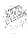
- the Fig. 1 shows a bottle crate 2 according to the invention in the form of a rectangular container with a rectangular bottle case bottom 4 of the latter Edges extend substantially vertically two long side walls 6 and two short side walls 8. In the short side walls handle and view openings are formed.
- a truss 10 is used in the open-topped bottle crate 2 .
- the truss insert 10 has a framework-like structure, which has openings 12 which form bottle nests, in the bottles 14 (see Fig. 10 ) can be adjusted.
- the truss insert 10 has essentially the function to laterally support and separate the adjusted bottles 14.
- Bottle crate 2 and truss 10 are separately manufactured for bottle crate 2 component that can be inserted from above into the bottle crate 2 and also taken out of this again.
- Bottle crate 2 and truss 10 can be made of plastic, in particular by injection molding.
- the truss 10 is guided vertically on the two opposite long side walls 6 and slightly spaced from the two opposite short side walls 8.
- On the inside 16 of the long side walls 6 a plurality of guide grooves 18, 20 and 22 are formed. These guide grooves 18, 20 and 22 will be described with reference to FIGS Fig. 2 described in detail.
- the Fig. 2 shows the bottle case 2 without the truss insert 10.
- On the inside 16 of the long side wall 6 is a centrally arranged, semi-cylindrically shaped and the truss floor 4 to the bottle crate edge 24 extending main guide groove 18 is formed.
- the main guide groove 18 serves for the general vertical guidance of the truss insert 10.
- the long guide grooves 20 form with a pair of guide projections 30 which are formed on an outer side (34) of the truss insert 10 (see Fig. 3 ), a first guide pair and the short guide grooves 22 form with the guide projections 30 a second guide pair.
- the long guide grooves 20 and the short guide grooves 22 are formed on the opposite long side wall 6 exactly the other way round, so that when the truss 10 in the orientation, as in the Fig. 3 is inserted into the bottle crate 2, the two asymmetrically and on opposite sides arranged guide projections 30 are inserted into the short guide grooves 22.
- the truss 10 can be lowered only up to a height H, since the lower end of the short guide 22 forms a stop for the guide projections 30.
- the guide projections 30 come into engagement with the long guide grooves 20 which extend to the bottle case bottom 4, which is why the truss 10 can be lowered to the bottle case bottom 4.
- the long and short guide grooves 20, 22 are slightly undercut and have a T-profile, so that the example corresponding T-shaped projections 30 in the guide grooves 20 and 22, although vertically movable, but trapped in the transverse direction ..
- the T-shape is optional and not visualized in the figures.
- These guide grooves 20 and 22 may alternatively be round, square or are formed dovetailed.
- the long and short guide grooves 20, 22 run upwards open.
- one or more of the grooves 20, 22 may also be closed at the top of the bottle crate rim 24, so that the truss insert 10 can be removed from the bottle crate 2 only by slight tilting.
- the long side wall 6 in a central portion has a slightly recessed wall portion 32, in which also the grooves 18, 20 and 22 are formed.
- the withdrawn wall section 32 serves as a sliding surface for an outer wall section or peripheral wall section 34 of the truss insert 10.
- truss ribs or projections 36 are formed, which are chamfered in the crossing points and pass into the bottle case bottom 4.
- the truss ribs 36 are substantially complementary to the surface design of the one side of the truss insert 10 (upper side in the Fig. 3 ), which has insertion chamfers 38 between the truss openings 12.
- the chamfers 38 are cross-shaped rising ribs at the intersection of the half-timbered partitions 40. In an attempt to set a bottle 14 in one of the openings 12, direct two adjacent chamfers the bottom of the bottle to the next opening 12th
- the other side of the truss insert 10, ie the bottom in the Fig. 3 is flat so that when the truss 10 is turned over and lowered to the bottle crate bottom 4, as in the Fig. 1 and in detail in the Fig. 4 is shown, a flat footprint for the beverage composites 15 (see Fig. 9 ) offers.
- Fig. 4 is also very good to see the interaction of truss ribs 36 and insertion bevels 38, so that the truss 10 rests on all chamfers 38 and half-timbered partitions 40.
- the one by the lattice-shaped framework divisions 40 formed truss 10 has in the corner regions of the openings 12 (see, in particular Fig. 1 ) integrally formed cylindrical segments 42 (see in particular Fig. 3 ), which support the bottles used 14 laterally flat.
- the FIG. 4 visualizes the interaction of selected or all guide grooves 20, each with at least one projection 30.
- groove and projection can also be such that the groove is present on the truss insert and the projection is formed on an inner wall of the bottle crate.
- the projection may be T-shaped or dovetail-shaped. Opposite grooves then allow an undercut and / or a grip behind.
- the Indian Fig. 3 shown truss insert 10 has 6 x 4 bottle spaces, the two outer, the short side walls 8 facing parking spaces are defined in conjunction with the short side wall 8.
- the latticework insert 10 has only separating projections 44, which are completed by corresponding truss lugs 46 which are formed in the edge region between the bottle case bottom 4 and the short side wall 8.
- the Fig. 5 shows a similar in basic form truss insert 50 according to a second embodiment, which can also be used with the bottle crate 2.
- This has no chamfers 38 and no guide projections 30.
- the truss 50 on the outside, which is associated with the inner side 16 of the long side wall 6, a central semi-cylindrical main guide projection 52 which can slide vertically in the main guide 18.
- Symmetric to this is a pair of spring elastic Locking tongues 54 are formed, which are designed in terms of their position and function so that they engage in the recesses 26 when the truss insert 50 is at the height H, and engage in the recesses 28 when the truss insert 50 is lowered to the bottle case bottom.
- the resilient locking tongues 54 yield and release the truss insert 50.
- the lock hook 56 and the recesses 26 and 28 may be formed so that the lock hook 56 is displaced by corresponding inclinations when reciprocated between the bottle case bottom 4 and the height H.
- the locking hook 56 and the recesses 26 are designed so that the truss can not be easily removed.
- the locking hooks 56 must be manually unlocked by the locking hooks 56, for example, with a sharp object such. As a screwdriver, pressed from the outside through the recess 26 through inside and released. This prevents that the truss 50 is not inadvertently removed from the bottle crate 2 in normal use. Instead of a manual unlocking the automatic unlocking can only be difficult.
- the truss 10 of the first embodiment in the truss insert 50 of the second embodiment is not a reversing fan insert and the truss 50 in the in the Fig. 5 shown orientation in the bottle crate 2 is introduced and can be moved without alignment changes between the height H and the bottle case bottom 4.
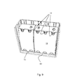
- the Fig. 6 shows a third embodiment of a truss 60, which is designed for a differently designed bottle crate 62, but in principle similar to the second embodiment.
- the truss 60 has a rectangular plate-shaped basic shape, which has a plurality of openings 64, the bottle nests form.
- a pair of snap elements 66 arranged symmetrically to the center, which automatically engage in corresponding recesses 68 which are formed at the height H on the inside of the short side wall of the bottle crate 62.
- the snap elements 66 lock into corresponding recesses 72.
- the snap elements 66 In order to lift the truss 60 again, again the snap elements 66 must be pressed down to release the latch to the side walls of the bottle crate 62.
- the truss 60 has, on the long side, a plurality of sliding surface portions 74 that slide along respective inner surface portions 76 of the long side wall of the bottle crate 62. In addition, the truss 60 is also performed in sections on the short sides of the bottle crate 62.
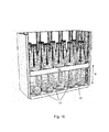
- FIGS. 9 and 10 show the example of the third embodiment, the principle of operation of the bottle crate according to the invention.
- Um like in the Fig. 9 shown to transport several beverage networks, ie several enveloped in cardboard boxes 15 bottles 14, the truss 60 can use up to the timber floor are lowered, so that the packaged bottles are flat on the hole plate-shaped truss 60 and are fully absorbed in the bottle crate 62.
- the cardboard boxes must be torn open, so that when returning the empties empty individual bottles must be transported, which are no longer held by the cardboard 15 and separated from each other.
- the truss 60 can be raised up to a predetermined height H and, due to the latching of the truss 60 with the bottle crate 62, the truss 60 remains at height H so that the bottles 14 can be transported separated and securely supported as shown in FIG of the Fig. 10 is shown.
- the same principle is applicable to the second embodiment.
- the truss 10 In the first embodiment, however, the truss 10 must first be removed, turned by 180 ° about the horizontal axis A and used again. Due to the interaction of the different guide pairings, the truss 10 remains in the height H, which is suitable for the transport of the individual bottles.
- the truss insert can be designed for a larger number of smaller bottles and also for a smaller number of larger bottles.
- the outer dimensions or at least the guide portions or locking elements are designed according to the same, a variety of trusses can be used with the same described bottle crate.
- the bottle crate 2 of the first embodiment is designed for both a truss 10 according to the first embodiment and a truss 50 of the second embodiment.
- the bottle crate 2 can also be designed only for one embodiment, so that z. B. in the use of truss 10, the Klein Replacementsnut 18 and the Recesses 26 and 28 and the use of a truss insert 50, the long and short guide grooves 20, 22 and the truss inserts 36 can be omitted.
- the features can be combined differently.
- the guide and / or locking the truss 10 could be done instead of on the side walls 6 in addition or alternative to so-called spars or quills in the center of the bottle crate.
- the sides of the turning tray insert 10 of the first embodiment can also be designed differently colored to align the truss 10 according to the desired use easier.
- the guide of the truss insert 10 takes place exclusively on the long side walls 6.
- the guides and the latches can also be formed on the short side.
- the guide on the long sides and the lock on the short sides or vice versa take place.
Landscapes
- Engineering & Computer Science (AREA)
- Mechanical Engineering (AREA)
- Ceramic Engineering (AREA)
- Details Of Rigid Or Semi-Rigid Containers (AREA)
Priority Applications (1)
| Application Number | Priority Date | Filing Date | Title |
|---|---|---|---|
| EP13177716.1A EP2829485B1 (fr) | 2013-07-23 | 2013-07-23 | Casier à bouteilles avec insert en treillis réglable en hauteur |
Applications Claiming Priority (1)
| Application Number | Priority Date | Filing Date | Title |
|---|---|---|---|
| EP13177716.1A EP2829485B1 (fr) | 2013-07-23 | 2013-07-23 | Casier à bouteilles avec insert en treillis réglable en hauteur |
Publications (2)
| Publication Number | Publication Date |
|---|---|
| EP2829485A1 true EP2829485A1 (fr) | 2015-01-28 |
| EP2829485B1 EP2829485B1 (fr) | 2017-08-30 |
Family
ID=48914054
Family Applications (1)
| Application Number | Title | Priority Date | Filing Date |
|---|---|---|---|
| EP13177716.1A Not-in-force EP2829485B1 (fr) | 2013-07-23 | 2013-07-23 | Casier à bouteilles avec insert en treillis réglable en hauteur |
Country Status (1)
| Country | Link |
|---|---|
| EP (1) | EP2829485B1 (fr) |
Cited By (18)
| Publication number | Priority date | Publication date | Assignee | Title |
|---|---|---|---|---|
| WO2015094708A1 (fr) * | 2013-12-16 | 2015-06-25 | Poly Flex Products, Inc. | Conteneur industriel ayant un fardage amovible |
| EP3124390A1 (fr) * | 2015-07-31 | 2017-02-01 | D.W. Plastics | Casier à bouteilles avec élément de séparation amoviblec |
| USD904829S1 (en) | 2018-12-11 | 2020-12-15 | Yeti Coolers, Llc | Container accessories |
| USD907445S1 (en) | 2018-12-11 | 2021-01-12 | Yeti Coolers, Llc | Container accessories |
| US11203465B2 (en) | 2017-06-12 | 2021-12-21 | Yeti Coolers, Llc | Container and latching system |
| USD946894S1 (en) | 2017-06-12 | 2022-03-29 | Yeti Coolers, Llc | Container |
| USD951643S1 (en) | 2020-06-30 | 2022-05-17 | Yeti Coolers, Llc | Luggage |
| USD954436S1 (en) | 2020-06-30 | 2022-06-14 | Yeti Coolers, Llc | Luggage |
| USD960648S1 (en) | 2020-12-16 | 2022-08-16 | Yeti Coolers, Llc | Container accessory |
| USD961926S1 (en) | 2020-06-30 | 2022-08-30 | Yeti Coolers, Llc | Luggage |
| USD963344S1 (en) | 2020-06-30 | 2022-09-13 | Yeti Coolers, Llc | Luggage |
| US11517086B2 (en) | 2019-01-06 | 2022-12-06 | Yeti Coolers, Llc | Luggage system |
| USD985937S1 (en) | 2020-12-16 | 2023-05-16 | Yeti Coolers, Llc | Container |
| US11685573B2 (en) | 2017-06-12 | 2023-06-27 | Yeti Coolers, Llc | Carry strap for container |
| USD994438S1 (en) | 2020-12-16 | 2023-08-08 | Yeti Coolers, Llc | Container |
| US11976498B2 (en) | 2017-06-12 | 2024-05-07 | Yeti Coolers, Llc | Container and latching system |
| US12108853B2 (en) | 2019-01-06 | 2024-10-08 | Yeti Coolers, Llc | Luggage system |
| US12225993B2 (en) | 2019-01-06 | 2025-02-18 | Yeti Coolers, Llc | Luggage system |
Families Citing this family (1)
| Publication number | Priority date | Publication date | Assignee | Title |
|---|---|---|---|---|
| EP4556386A1 (fr) | 2023-11-18 | 2025-05-21 | DW Reusables N.V. | Caisse pour bouteilles de deux géométries sensiblement différentes |
Citations (10)
| Publication number | Priority date | Publication date | Assignee | Title |
|---|---|---|---|---|
| US2119889A (en) | 1935-05-03 | 1938-06-07 | American Steel & Wire Co | Partition |
| DE1748170U (de) | 1957-03-29 | 1957-07-04 | Schaefer Kg Fritz | Einsatz fuer flaschenkaesten. |
| GB873288A (en) | 1959-02-11 | 1961-07-19 | W E Amies & Company Ltd | Improvements in crates for bottles |
| DE1839065U (de) | 1961-06-16 | 1961-10-05 | Karl Henninger | Kunststoff-flaschenkasten. |
| AT315724B (de) * | 1970-11-09 | 1974-06-10 | Utz Ag Georg | Stapelbarer Haraß für Flaschen, Dosen od.dgl. |
| US4113329A (en) * | 1977-05-12 | 1978-09-12 | Dare Pafco, Inc. | Multi-tray basket |
| US5392915A (en) * | 1993-09-03 | 1995-02-28 | Rehrig-Pacific Company, Inc. | Crate apparatus with adjustable lid |
| EP0655397A1 (fr) | 1993-11-25 | 1995-05-31 | Schoeller-Plast S.A. | Caisse à bouteilles avec cloisonnage insérable |
| AU716767B2 (en) * | 1996-03-06 | 2000-03-09 | Otto Plastics Pty Ltd | A crate with slidable side barrier |
| EP1637470A1 (fr) | 2004-09-17 | 2006-03-22 | Berndt & Partner GmbH | Cloisonnage insérable pour casier |
-
2013
- 2013-07-23 EP EP13177716.1A patent/EP2829485B1/fr not_active Not-in-force
Patent Citations (10)
| Publication number | Priority date | Publication date | Assignee | Title |
|---|---|---|---|---|
| US2119889A (en) | 1935-05-03 | 1938-06-07 | American Steel & Wire Co | Partition |
| DE1748170U (de) | 1957-03-29 | 1957-07-04 | Schaefer Kg Fritz | Einsatz fuer flaschenkaesten. |
| GB873288A (en) | 1959-02-11 | 1961-07-19 | W E Amies & Company Ltd | Improvements in crates for bottles |
| DE1839065U (de) | 1961-06-16 | 1961-10-05 | Karl Henninger | Kunststoff-flaschenkasten. |
| AT315724B (de) * | 1970-11-09 | 1974-06-10 | Utz Ag Georg | Stapelbarer Haraß für Flaschen, Dosen od.dgl. |
| US4113329A (en) * | 1977-05-12 | 1978-09-12 | Dare Pafco, Inc. | Multi-tray basket |
| US5392915A (en) * | 1993-09-03 | 1995-02-28 | Rehrig-Pacific Company, Inc. | Crate apparatus with adjustable lid |
| EP0655397A1 (fr) | 1993-11-25 | 1995-05-31 | Schoeller-Plast S.A. | Caisse à bouteilles avec cloisonnage insérable |
| AU716767B2 (en) * | 1996-03-06 | 2000-03-09 | Otto Plastics Pty Ltd | A crate with slidable side barrier |
| EP1637470A1 (fr) | 2004-09-17 | 2006-03-22 | Berndt & Partner GmbH | Cloisonnage insérable pour casier |
Cited By (33)
| Publication number | Priority date | Publication date | Assignee | Title |
|---|---|---|---|---|
| WO2015094708A1 (fr) * | 2013-12-16 | 2015-06-25 | Poly Flex Products, Inc. | Conteneur industriel ayant un fardage amovible |
| EP3124390A1 (fr) * | 2015-07-31 | 2017-02-01 | D.W. Plastics | Casier à bouteilles avec élément de séparation amoviblec |
| US11203465B2 (en) | 2017-06-12 | 2021-12-21 | Yeti Coolers, Llc | Container and latching system |
| USD1103620S1 (en) | 2017-06-12 | 2025-12-02 | Yeti Coolers, Llc | Container |
| US11976498B2 (en) | 2017-06-12 | 2024-05-07 | Yeti Coolers, Llc | Container and latching system |
| US11685573B2 (en) | 2017-06-12 | 2023-06-27 | Yeti Coolers, Llc | Carry strap for container |
| USD946894S1 (en) | 2017-06-12 | 2022-03-29 | Yeti Coolers, Llc | Container |
| USD1033158S1 (en) | 2018-12-11 | 2024-07-02 | Yeti Coolers, Llc | Container accessories |
| USD925991S1 (en) | 2018-12-11 | 2021-07-27 | Yeti Coolers, Llc | Container accessories |
| USD904829S1 (en) | 2018-12-11 | 2020-12-15 | Yeti Coolers, Llc | Container accessories |
| USD959208S1 (en) | 2018-12-11 | 2022-08-02 | Yeti Coolers, Llc | Caddy accessory |
| USD960656S1 (en) | 2018-12-11 | 2022-08-16 | Yeti Coolers, Llc | Bag accessory |
| USD929814S1 (en) | 2018-12-11 | 2021-09-07 | Yeti Coolers, Llc | Container accessories |
| USD962010S1 (en) | 2018-12-11 | 2022-08-30 | Yeti Coolers, Llc | Divider accessory |
| USD907445S1 (en) | 2018-12-11 | 2021-01-12 | Yeti Coolers, Llc | Container accessories |
| USD925299S1 (en) | 2018-12-11 | 2021-07-20 | Yeti Coolers, Llc | Container accessories |
| US12225993B2 (en) | 2019-01-06 | 2025-02-18 | Yeti Coolers, Llc | Luggage system |
| US12108853B2 (en) | 2019-01-06 | 2024-10-08 | Yeti Coolers, Llc | Luggage system |
| US11517086B2 (en) | 2019-01-06 | 2022-12-06 | Yeti Coolers, Llc | Luggage system |
| USD961926S1 (en) | 2020-06-30 | 2022-08-30 | Yeti Coolers, Llc | Luggage |
| USD963344S1 (en) | 2020-06-30 | 2022-09-13 | Yeti Coolers, Llc | Luggage |
| USD951643S1 (en) | 2020-06-30 | 2022-05-17 | Yeti Coolers, Llc | Luggage |
| USD954436S1 (en) | 2020-06-30 | 2022-06-14 | Yeti Coolers, Llc | Luggage |
| USD985937S1 (en) | 2020-12-16 | 2023-05-16 | Yeti Coolers, Llc | Container |
| USD994438S1 (en) | 2020-12-16 | 2023-08-08 | Yeti Coolers, Llc | Container |
| USD960648S1 (en) | 2020-12-16 | 2022-08-16 | Yeti Coolers, Llc | Container accessory |
| USD1014969S1 (en) | 2020-12-16 | 2024-02-20 | Yeti Coolers, Llc | Container |
| USD1080202S1 (en) | 2020-12-16 | 2025-06-24 | Yeti Coolers, Llc | Container |
| USD1082440S1 (en) | 2020-12-16 | 2025-07-08 | Yeti Coolers, Llc | Container accessory |
| USD1085823S1 (en) | 2020-12-16 | 2025-07-29 | Yeti Coolers, Llc | Container |
| USD1096326S1 (en) | 2020-12-16 | 2025-10-07 | Yeti Coolers, Llc | Container |
| USD1014965S1 (en) | 2020-12-16 | 2024-02-20 | Yeti Coolers, Llc | Container |
| USD1108148S1 (en) | 2020-12-16 | 2026-01-06 | Yeti Coolers, Llc | Container |
Also Published As
| Publication number | Publication date |
|---|---|
| EP2829485B1 (fr) | 2017-08-30 |
Similar Documents
| Publication | Publication Date | Title |
|---|---|---|
| EP2829485B1 (fr) | Casier à bouteilles avec insert en treillis réglable en hauteur | |
| EP2829484B1 (fr) | Casier à bouteilles avec insert en treillis réglable en hauteur | |
| EP0389802B1 (fr) | Récipient séparable en plusieurs parties, en particulier casier à bouteilles | |
| DE10026149C2 (de) | Stapelbarer Transportbehälter | |
| EP1730042B1 (fr) | Combinaison de bacs empilables par rotation et de differentes dimensions | |
| DE69321363T2 (de) | Flaschenkastenanordnung | |
| DE202014103695U1 (de) | Stapelbarer Behälter | |
| EP3587294B1 (fr) | Récipient empilable pourvu de mécanisme de raccordement | |
| WO2018010858A1 (fr) | Contenant modulaire empilable | |
| EP2878548A1 (fr) | Palette | |
| EP3636559A1 (fr) | Boîte empilable | |
| DE102019111950A1 (de) | Stapelbare Lagereinheit und Stapel aus Lagereinheiten | |
| DE2525169C3 (de) | Kunststoff-Flaschenkasten mit Verriegelungsvorrichtung | |
| DE19713691C2 (de) | Behälter | |
| EP2840034A1 (fr) | Dispositif de verrouillage et de déverrouillage des parois latérales rabattables ou pliables d'un récipient | |
| DE2104389A1 (de) | Gleichzeitig als Flaschenträger und Stapelkasten ausgebildeter Flaschenkasten | |
| EP0374774A2 (fr) | Casiers à bouteilles avec des éléments horizontaux servant de poignées | |
| DE102014111337A1 (de) | Stapelbarer Behälter | |
| EP0698558A2 (fr) | Récipient de transport empilable | |
| WO2007115806A1 (fr) | Recipient de transport empilable | |
| DE202004016511U1 (de) | Behälter mit klappbaren Seitenwänden für Portionsschalen | |
| DE102015009734B4 (de) | Anreihbare Einzelverpackung | |
| EP4410696B1 (fr) | Conteneur et pile de conteneurs | |
| EP3012205B1 (fr) | Caisse a bouteilles divisible | |
| AT413689B (de) | Zerlegbare box |
Legal Events
| Date | Code | Title | Description |
|---|---|---|---|
| 17P | Request for examination filed |
Effective date: 20130723 |
|
| AK | Designated contracting states |
Kind code of ref document: A1 Designated state(s): AL AT BE BG CH CY CZ DE DK EE ES FI FR GB GR HR HU IE IS IT LI LT LU LV MC MK MT NL NO PL PT RO RS SE SI SK SM TR |
|
| AX | Request for extension of the european patent |
Extension state: BA ME |
|
| PUAI | Public reference made under article 153(3) epc to a published international application that has entered the european phase |
Free format text: ORIGINAL CODE: 0009012 |
|
| R17P | Request for examination filed (corrected) |
Effective date: 20150629 |
|
| RBV | Designated contracting states (corrected) |
Designated state(s): AL AT BE BG CH CY CZ DE DK EE ES FI FR GB GR HR HU IE IS IT LI LT LU LV MC MK MT NL NO PL PT RO RS SE SI SK SM TR |
|
| 17Q | First examination report despatched |
Effective date: 20151116 |
|
| REG | Reference to a national code |
Ref country code: DE Ref legal event code: R079 Ref document number: 502013008189 Country of ref document: DE Free format text: PREVIOUS MAIN CLASS: B65D0001240000 Ipc: B65D0025100000 |
|
| GRAP | Despatch of communication of intention to grant a patent |
Free format text: ORIGINAL CODE: EPIDOSNIGR1 |
|
| RIC1 | Information provided on ipc code assigned before grant |
Ipc: B65D 25/10 20060101AFI20170216BHEP Ipc: B65D 1/24 20060101ALI20170216BHEP |
|
| INTG | Intention to grant announced |
Effective date: 20170310 |
|
| GRAS | Grant fee paid |
Free format text: ORIGINAL CODE: EPIDOSNIGR3 |
|
| GRAA | (expected) grant |
Free format text: ORIGINAL CODE: 0009210 |
|
| AK | Designated contracting states |
Kind code of ref document: B1 Designated state(s): AL AT BE BG CH CY CZ DE DK EE ES FI FR GB GR HR HU IE IS IT LI LT LU LV MC MK MT NL NO PL PT RO RS SE SI SK SM TR |
|
| REG | Reference to a national code |
Ref country code: GB Ref legal event code: FG4D Free format text: NOT ENGLISH |
|
| REG | Reference to a national code |
Ref country code: CH Ref legal event code: EP |
|
| REG | Reference to a national code |
Ref country code: AT Ref legal event code: REF Ref document number: 923296 Country of ref document: AT Kind code of ref document: T Effective date: 20170915 |
|
| REG | Reference to a national code |
Ref country code: IE Ref legal event code: FG4D Free format text: LANGUAGE OF EP DOCUMENT: GERMAN |
|
| REG | Reference to a national code |
Ref country code: DE Ref legal event code: R096 Ref document number: 502013008189 Country of ref document: DE |
|
| REG | Reference to a national code |
Ref country code: NL Ref legal event code: FP |
|
| REG | Reference to a national code |
Ref country code: LT Ref legal event code: MG4D |
|
| PG25 | Lapsed in a contracting state [announced via postgrant information from national office to epo] |
Ref country code: NO Free format text: LAPSE BECAUSE OF FAILURE TO SUBMIT A TRANSLATION OF THE DESCRIPTION OR TO PAY THE FEE WITHIN THE PRESCRIBED TIME-LIMIT Effective date: 20171130 Ref country code: HR Free format text: LAPSE BECAUSE OF FAILURE TO SUBMIT A TRANSLATION OF THE DESCRIPTION OR TO PAY THE FEE WITHIN THE PRESCRIBED TIME-LIMIT Effective date: 20170830 Ref country code: SE Free format text: LAPSE BECAUSE OF FAILURE TO SUBMIT A TRANSLATION OF THE DESCRIPTION OR TO PAY THE FEE WITHIN THE PRESCRIBED TIME-LIMIT Effective date: 20170830 Ref country code: LT Free format text: LAPSE BECAUSE OF FAILURE TO SUBMIT A TRANSLATION OF THE DESCRIPTION OR TO PAY THE FEE WITHIN THE PRESCRIBED TIME-LIMIT Effective date: 20170830 Ref country code: FI Free format text: LAPSE BECAUSE OF FAILURE TO SUBMIT A TRANSLATION OF THE DESCRIPTION OR TO PAY THE FEE WITHIN THE PRESCRIBED TIME-LIMIT Effective date: 20170830 |
|
| PG25 | Lapsed in a contracting state [announced via postgrant information from national office to epo] |
Ref country code: RS Free format text: LAPSE BECAUSE OF FAILURE TO SUBMIT A TRANSLATION OF THE DESCRIPTION OR TO PAY THE FEE WITHIN THE PRESCRIBED TIME-LIMIT Effective date: 20170830 Ref country code: GR Free format text: LAPSE BECAUSE OF FAILURE TO SUBMIT A TRANSLATION OF THE DESCRIPTION OR TO PAY THE FEE WITHIN THE PRESCRIBED TIME-LIMIT Effective date: 20171201 Ref country code: ES Free format text: LAPSE BECAUSE OF FAILURE TO SUBMIT A TRANSLATION OF THE DESCRIPTION OR TO PAY THE FEE WITHIN THE PRESCRIBED TIME-LIMIT Effective date: 20170830 Ref country code: LV Free format text: LAPSE BECAUSE OF FAILURE TO SUBMIT A TRANSLATION OF THE DESCRIPTION OR TO PAY THE FEE WITHIN THE PRESCRIBED TIME-LIMIT Effective date: 20170830 Ref country code: IS Free format text: LAPSE BECAUSE OF FAILURE TO SUBMIT A TRANSLATION OF THE DESCRIPTION OR TO PAY THE FEE WITHIN THE PRESCRIBED TIME-LIMIT Effective date: 20171230 Ref country code: BG Free format text: LAPSE BECAUSE OF FAILURE TO SUBMIT A TRANSLATION OF THE DESCRIPTION OR TO PAY THE FEE WITHIN THE PRESCRIBED TIME-LIMIT Effective date: 20171130 |
|
| PG25 | Lapsed in a contracting state [announced via postgrant information from national office to epo] |
Ref country code: DK Free format text: LAPSE BECAUSE OF FAILURE TO SUBMIT A TRANSLATION OF THE DESCRIPTION OR TO PAY THE FEE WITHIN THE PRESCRIBED TIME-LIMIT Effective date: 20170830 Ref country code: CZ Free format text: LAPSE BECAUSE OF FAILURE TO SUBMIT A TRANSLATION OF THE DESCRIPTION OR TO PAY THE FEE WITHIN THE PRESCRIBED TIME-LIMIT Effective date: 20170830 Ref country code: RO Free format text: LAPSE BECAUSE OF FAILURE TO SUBMIT A TRANSLATION OF THE DESCRIPTION OR TO PAY THE FEE WITHIN THE PRESCRIBED TIME-LIMIT Effective date: 20170830 Ref country code: PL Free format text: LAPSE BECAUSE OF FAILURE TO SUBMIT A TRANSLATION OF THE DESCRIPTION OR TO PAY THE FEE WITHIN THE PRESCRIBED TIME-LIMIT Effective date: 20170830 |
|
| PG25 | Lapsed in a contracting state [announced via postgrant information from national office to epo] |
Ref country code: SK Free format text: LAPSE BECAUSE OF FAILURE TO SUBMIT A TRANSLATION OF THE DESCRIPTION OR TO PAY THE FEE WITHIN THE PRESCRIBED TIME-LIMIT Effective date: 20170830 Ref country code: IT Free format text: LAPSE BECAUSE OF FAILURE TO SUBMIT A TRANSLATION OF THE DESCRIPTION OR TO PAY THE FEE WITHIN THE PRESCRIBED TIME-LIMIT Effective date: 20170830 Ref country code: EE Free format text: LAPSE BECAUSE OF FAILURE TO SUBMIT A TRANSLATION OF THE DESCRIPTION OR TO PAY THE FEE WITHIN THE PRESCRIBED TIME-LIMIT Effective date: 20170830 Ref country code: SM Free format text: LAPSE BECAUSE OF FAILURE TO SUBMIT A TRANSLATION OF THE DESCRIPTION OR TO PAY THE FEE WITHIN THE PRESCRIBED TIME-LIMIT Effective date: 20170830 |
|
| REG | Reference to a national code |
Ref country code: DE Ref legal event code: R097 Ref document number: 502013008189 Country of ref document: DE |
|
| PLBE | No opposition filed within time limit |
Free format text: ORIGINAL CODE: 0009261 |
|
| STAA | Information on the status of an ep patent application or granted ep patent |
Free format text: STATUS: NO OPPOSITION FILED WITHIN TIME LIMIT |
|
| 26N | No opposition filed |
Effective date: 20180531 |
|
| PG25 | Lapsed in a contracting state [announced via postgrant information from national office to epo] |
Ref country code: SI Free format text: LAPSE BECAUSE OF FAILURE TO SUBMIT A TRANSLATION OF THE DESCRIPTION OR TO PAY THE FEE WITHIN THE PRESCRIBED TIME-LIMIT Effective date: 20170830 |
|
| PG25 | Lapsed in a contracting state [announced via postgrant information from national office to epo] |
Ref country code: MT Free format text: LAPSE BECAUSE OF FAILURE TO SUBMIT A TRANSLATION OF THE DESCRIPTION OR TO PAY THE FEE WITHIN THE PRESCRIBED TIME-LIMIT Effective date: 20170830 |
|
| REG | Reference to a national code |
Ref country code: CH Ref legal event code: PL |
|
| GBPC | Gb: european patent ceased through non-payment of renewal fee |
Effective date: 20180723 |
|
| PG25 | Lapsed in a contracting state [announced via postgrant information from national office to epo] |
Ref country code: MC Free format text: LAPSE BECAUSE OF FAILURE TO SUBMIT A TRANSLATION OF THE DESCRIPTION OR TO PAY THE FEE WITHIN THE PRESCRIBED TIME-LIMIT Effective date: 20170830 Ref country code: LU Free format text: LAPSE BECAUSE OF NON-PAYMENT OF DUE FEES Effective date: 20180723 |
|
| REG | Reference to a national code |
Ref country code: IE Ref legal event code: MM4A |
|
| PG25 | Lapsed in a contracting state [announced via postgrant information from national office to epo] |
Ref country code: CH Free format text: LAPSE BECAUSE OF NON-PAYMENT OF DUE FEES Effective date: 20180731 Ref country code: GB Free format text: LAPSE BECAUSE OF NON-PAYMENT OF DUE FEES Effective date: 20180723 Ref country code: FR Free format text: LAPSE BECAUSE OF NON-PAYMENT OF DUE FEES Effective date: 20180731 Ref country code: LI Free format text: LAPSE BECAUSE OF NON-PAYMENT OF DUE FEES Effective date: 20180731 Ref country code: IE Free format text: LAPSE BECAUSE OF NON-PAYMENT OF DUE FEES Effective date: 20180723 |
|
| PGFP | Annual fee paid to national office [announced via postgrant information from national office to epo] |
Ref country code: NL Payment date: 20190722 Year of fee payment: 7 |
|
| REG | Reference to a national code |
Ref country code: AT Ref legal event code: MM01 Ref document number: 923296 Country of ref document: AT Kind code of ref document: T Effective date: 20180723 |
|
| PGFP | Annual fee paid to national office [announced via postgrant information from national office to epo] |
Ref country code: DE Payment date: 20190628 Year of fee payment: 7 |
|
| PGFP | Annual fee paid to national office [announced via postgrant information from national office to epo] |
Ref country code: BE Payment date: 20190722 Year of fee payment: 7 |
|
| PG25 | Lapsed in a contracting state [announced via postgrant information from national office to epo] |
Ref country code: AT Free format text: LAPSE BECAUSE OF NON-PAYMENT OF DUE FEES Effective date: 20180723 |
|
| PG25 | Lapsed in a contracting state [announced via postgrant information from national office to epo] |
Ref country code: TR Free format text: LAPSE BECAUSE OF FAILURE TO SUBMIT A TRANSLATION OF THE DESCRIPTION OR TO PAY THE FEE WITHIN THE PRESCRIBED TIME-LIMIT Effective date: 20170830 |
|
| PG25 | Lapsed in a contracting state [announced via postgrant information from national office to epo] |
Ref country code: HU Free format text: LAPSE BECAUSE OF FAILURE TO SUBMIT A TRANSLATION OF THE DESCRIPTION OR TO PAY THE FEE WITHIN THE PRESCRIBED TIME-LIMIT; INVALID AB INITIO Effective date: 20130723 Ref country code: PT Free format text: LAPSE BECAUSE OF FAILURE TO SUBMIT A TRANSLATION OF THE DESCRIPTION OR TO PAY THE FEE WITHIN THE PRESCRIBED TIME-LIMIT Effective date: 20170830 |
|
| PG25 | Lapsed in a contracting state [announced via postgrant information from national office to epo] |
Ref country code: MK Free format text: LAPSE BECAUSE OF NON-PAYMENT OF DUE FEES Effective date: 20170830 Ref country code: CY Free format text: LAPSE BECAUSE OF FAILURE TO SUBMIT A TRANSLATION OF THE DESCRIPTION OR TO PAY THE FEE WITHIN THE PRESCRIBED TIME-LIMIT Effective date: 20170830 |
|
| PG25 | Lapsed in a contracting state [announced via postgrant information from national office to epo] |
Ref country code: AL Free format text: LAPSE BECAUSE OF FAILURE TO SUBMIT A TRANSLATION OF THE DESCRIPTION OR TO PAY THE FEE WITHIN THE PRESCRIBED TIME-LIMIT Effective date: 20170830 |
|
| REG | Reference to a national code |
Ref country code: DE Ref legal event code: R119 Ref document number: 502013008189 Country of ref document: DE |
|
| REG | Reference to a national code |
Ref country code: NL Ref legal event code: MM Effective date: 20200801 |
|
| REG | Reference to a national code |
Ref country code: BE Ref legal event code: MM Effective date: 20200731 |
|
| PG25 | Lapsed in a contracting state [announced via postgrant information from national office to epo] |
Ref country code: NL Free format text: LAPSE BECAUSE OF NON-PAYMENT OF DUE FEES Effective date: 20200801 |
|
| PG25 | Lapsed in a contracting state [announced via postgrant information from national office to epo] |
Ref country code: BE Free format text: LAPSE BECAUSE OF NON-PAYMENT OF DUE FEES Effective date: 20200731 Ref country code: DE Free format text: LAPSE BECAUSE OF NON-PAYMENT OF DUE FEES Effective date: 20210202 |