EP2829492A1 - Lebensmittelbehälter - Google Patents
Lebensmittelbehälter Download PDFInfo
- Publication number
- EP2829492A1 EP2829492A1 EP13763447.3A EP13763447A EP2829492A1 EP 2829492 A1 EP2829492 A1 EP 2829492A1 EP 13763447 A EP13763447 A EP 13763447A EP 2829492 A1 EP2829492 A1 EP 2829492A1
- Authority
- EP
- European Patent Office
- Prior art keywords
- spoon
- container
- food
- wall portion
- container body
- Prior art date
- Legal status (The legal status is an assumption and is not a legal conclusion. Google has not performed a legal analysis and makes no representation as to the accuracy of the status listed.)
- Withdrawn
Links
Images


Classifications
-
- A—HUMAN NECESSITIES
- A47—FURNITURE; DOMESTIC ARTICLES OR APPLIANCES; COFFEE MILLS; SPICE MILLS; SUCTION CLEANERS IN GENERAL
- A47G—HOUSEHOLD OR TABLE EQUIPMENT
- A47G19/00—Table service
- A47G19/02—Plates, dishes or the like
-
- B—PERFORMING OPERATIONS; TRANSPORTING
- B65—CONVEYING; PACKING; STORING; HANDLING THIN OR FILAMENTARY MATERIAL
- B65D—CONTAINERS FOR STORAGE OR TRANSPORT OF ARTICLES OR MATERIALS, e.g. BAGS, BARRELS, BOTTLES, BOXES, CANS, CARTONS, CRATES, DRUMS, JARS, TANKS, HOPPERS, FORWARDING CONTAINERS; ACCESSORIES, CLOSURES, OR FITTINGS THEREFOR; PACKAGING ELEMENTS; PACKAGES
- B65D1/00—Rigid or semi-rigid containers having bodies formed in one piece, e.g. by casting metallic material, by moulding plastics, by blowing vitreous material, by throwing ceramic material, by moulding pulped fibrous material or by deep-drawing operations performed on sheet material
- B65D1/22—Boxes or like containers with side walls of substantial depth for enclosing contents
- B65D1/26—Thin-walled containers, e.g. formed by deep-drawing operations
-
- B—PERFORMING OPERATIONS; TRANSPORTING
- B65—CONVEYING; PACKING; STORING; HANDLING THIN OR FILAMENTARY MATERIAL
- B65D—CONTAINERS FOR STORAGE OR TRANSPORT OF ARTICLES OR MATERIALS, e.g. BAGS, BARRELS, BOTTLES, BOXES, CANS, CARTONS, CRATES, DRUMS, JARS, TANKS, HOPPERS, FORWARDING CONTAINERS; ACCESSORIES, CLOSURES, OR FITTINGS THEREFOR; PACKAGING ELEMENTS; PACKAGES
- B65D1/00—Rigid or semi-rigid containers having bodies formed in one piece, e.g. by casting metallic material, by moulding plastics, by blowing vitreous material, by throwing ceramic material, by moulding pulped fibrous material or by deep-drawing operations performed on sheet material
- B65D1/34—Trays or like shallow containers
Definitions
- the present invention relates to a container for food, which can package a food.
- a container for food which is formed in a shape to assist the action of scooping a food by a spoon, so that the container serves as a self-help tool to be used by a young child or a care-requiring person who suffers deterioration and/or hypofunction of the upper limb, or serves as a nursing-care tool to be used by a caregiver or a protector of a young child.
- Japanese Utility Model No. 3022573 discloses a tableware deep plate that has a vertical wall surface on one side and an inclined wall surface on the other side.
- a container of this kind can be used to easily scoop a food by a spoon by bringing it into contact with the wall surface on the one side and moving it upward, and further to easily operate the spoon by guiding it along the wall surface on the other side.
- a technique of forming a plurality of ribs in a circumferential direction on this container for food so that a plurality of containers can be stacked each other.
- Jpn. Pat. Appln. KOKAI Publication No. 2002-240858 discloses a container for eating, in which one side of the container peripheral wall is bent inward in a circular arc form toward the container main body, and a readily peelable adhesive is attached on the rear surface of the bottom portion.
- a container for eating of this kind can be used to make a food into a shape to be easily put in a user's mouth, by use of the bent peripheral wall, i.e., by pulling up a spoon along the bent peripheral wall. Further, this container for eating can be fixedly mounted on a table by use of the readily peelable adhesive on the rear surface of the bottom portion.
- Patent Document 2 also discloses a technique for utilizing the container for eating as a package container for packaging a food.
- each of the containers for food disclosed in Japanese Utility Model No. 3022573 and Jpn. Pat. Appln. KOKAI Publication No. 2002-240858 has a circular shape in a view from above, and so has a problem such that the spoon insertion side cannot be easily recognized at a glance, i.e., it is poor in visibility.
- each of these containers for food has a circular shape in a view from above, and so, when a spoon is placed to stand and lean on the rim of the container, the spoon may move along this rim and fall down into the container. In this case, a problem arises such that the spoon cannot be easily picked up at resumption of eating.
- one side of the peripheral wall is bent inward in a circular arc form toward the container main body, and so the spoon moving distance becomes longer. Further, as regards the spoon moving directions, it is necessary to perform a so-called spoon turnabout operation, which is to move the spoon in a forward direction and then in a backward direction and in up and down directions.
- the container for food When the container for food is used as a nursing-care tool, it is easier to perform the spoon turnabout operation because a caregiver uses the spoon. However, when the container for food is used as a self-help tool, it is difficult to perform the spoon turnabout operation, and so the use of the container for food may be limited. Further, since the bent peripheral wall shades the food inside the container, a problem arises such that the food inside the container is poor in visibility.
- the container for food disclosed in Japanese Utility Model No. 3022573 requires ribs to be formed on its flange and thereby becomes complicated in structure.
- the container for food disclosed in Jpn. Pat. Appln. KOKAI Publication No. 2002-240858 is described as having a structure that includes ribs formed on the outer periphery of the upper surface along with a lid further placed thereon, when it is provided as a package container.
- the opening area is smaller than the bottom area, a problem arises such that containers of this type are difficult to stack and are poor in transportability when they are produced.
- an object of the present invention is to provide a container for food, which is high in usability.
- a container for food according to the present invention has a configuration as follows:
- a container for food which is high in usability.
- FIGS. 1 to 8 an explanation will be given of a container 1 for food according to an embodiment of the present invention, with reference to FIGS. 1 to 8 .
- FIG. 1 is a perspective view illustrating a configuration of the container 1 for food according to an embodiment of the present invention.
- FIG. 2 is a perspective view illustrating a configuration of a container body 2 used in the container 1 for food.
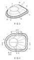
- FIG. 3 is a perspective view illustrating a configuration of the container body 2.
- FIG. 4 is a top view illustrating a configuration of the container body 2.
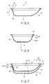
- FIG. 5 is a sectional view illustrating a configuration of the container body 2, taken along a line V-V in FIG. 4 .
- FIG. 6 is a sectional view illustrating a configuration of the container body 2, taken along a line VI-VI in FIG. 4 .
- FIG. 7 is a sectional view illustrating an example of use of the container body 2.
- FIG. 8 is a sectional view illustrating an example of use of the container body 2.
- the container 1 for food includes a container body 2 that holds a food 100, and a lid 3 that seals the container body 2.
- the container 1 for food is used as a self-help tool and/or nursing-care tool.
- the container 1 for food is used as a food package container, which has airtightness formed inside by the container body 2 and the lid 3, and packages the food 100.
- the container body 2 packages the food 100 in cooperation with the lid 3, and, after the lid 3 is removed, it further serves as a container for holding the food, which can be used a self-help tool and/or nursing-care tool.
- the container body 2 includes a bottom portion 11, a wall portion 12, and a flange portion 13.
- the bottom portion 11 is formed in a circular shape. As shown in FIG. 4 viewed from above, the center of the bottom portion 11 is present at a position eccentric toward one side from the gravity center (center) of the flange portion 13 and a second wall portion 22 described later.
- the wall portion 12 and the flange portion 13 are formed in a rectangular shape on one side and formed in a semielliptical shape on the other side, relative to the boundary position between a rectangular shape portion 24 and an elliptical shape portion 25 of the flange portion 13 described later. Further, as shown by a symmetrical shape of the semielliptical shape, which is illustrated with two-dot chain lines in FIG. 4 , the wall portion 12 and the flange portion 13 are formed such that the lengths in the longitudinal direction from the center of the flange portion 13 to the respective ends on the rectangular shape side and the elliptical shape side are almost equal to each other.
- the wall portion 12 is formed continuously from the bottom portion 11. As shown in FIGS. 2 , 3 and 5 , the wall portion 12 includes a first wall portion 21 extending from the bottom portion 11 and formed with a curved surface and an inclined surface in a predetermined manner, and a second wall portion 22 continuously connecting the upper end of the first wall portion 21 to the flange portion 13.
- the first wall portion 21 includes the rectangular shape portion 24 formed in a rectangular shape viewed from above and the elliptical shape portion 25 formed in a semielliptical shape viewed from above, such that these portions are respectively present on one and the other sides with the bottom portion 11 interposed therebetween.
- the rectangular shape portion 24 and the elliptical shape portion 25 are formed to have the same height from the bottom portion 11 to their upper ends.
- the rectangular shape portion 24 includes two linear portions that define end portions of a pair of lateral sides and one linear portion that defines an end portion orthogonal to the lateral sides and connects the two linear portions to form a rectangular shape, wherein the upper end peripheries of the two linear portions are continuous from the elliptical shape portion 25, when viewed from above.
- the rectangular shape portion 24 is formed with a curved surface within a range from the bottom portion 11 to its upper end.
- the curved surface forming the rectangular shape portion 24 has a predetermined curvature between the end connected to the bottom portion 11 and the end connected to the second wall portion 22.
- the elliptical shape portion 25 is formed with a curved surface, which has a predetermined curvature, at the end connected to the bottom portion 11, and is further continuously formed with an inclined surface, which has a predetermined angle relative to the main surface direction of the bottom portion 11, within a range from a halfway part of the curved surface to the end connected to the second wall portion 22.
- the curvature of the rectangular shape portion 24 is set smaller than the curvature of the curved surface of the elliptical shape portion 25.
- the curved surface of the rectangular shape portion 24 has a curvature radius larger than the curvature radius of the curved surface of the elliptical shape portion 25.
- first wall portion 21 is formed such that the distance from the bottom portion 11 to the outermost peripheral end of the elliptical shape portion 25 is smaller than the distance from the bottom portion 11 to the outermost peripheral end of the rectangular shape portion 24.
- the first wall portion 21 is formed such that the inclined surface continuously extending from the upper end of the elliptical shape portion 25 to the bottom portion 11 has an inclined angle larger than that of the inclined surface continuously extending from the upper end of the rectangular shape portion 24 to the bottom portion 11, at least on the second wall portion 22 side.
- the rectangular shape portion 24 is continuously present on one side relative to the center of the bottom portion 11, and the elliptical shape portion 25 is continuously present on the other side relative to the center of the bottom portion 11. Further, in the first wall portion 21, the rectangular shape portion 24 is continuously present on one side and the elliptical shape portion 25 is continuously present on the other side, relative to a near center of the second wall portion 22 in the longitudinal direction.
- the first wall portion 21 is formed such that, at its upper end, the distances from the boundary position between the rectangular shape portion 24 and the elliptical shape portion 25 to the respective outer peripheral ends of the rectangular shape portion 24 and the elliptical shape portion 25 are set equal to each other. Further, the first wall portion 21 is formed such that, at its end on the bottom portion 11 side, the distance from the center of the bottom portion 11 to the outer peripheral end of the elliptical shape portion 25 is smaller than the distance from the center of the bottom portion 11 to the outer peripheral end of the rectangular shape portion 24.
- the second wall portion 22 includes a first surface portion 31 formed at the upper end of the first wall portion 21, and a second surface portion 32 formed continuously from the first surface portion 31 and extending in a direction orthogonal to the surface direction of the bottom portion 11.
- the first surface portion 31 is formed in the surface direction of the bottom portion 11, continuously from the upper ends of the rectangular shape portion 24 and the elliptical shape portion 25.
- the first surface portion 31 is formed such that, when the container body 2 is stacked on another container body 2, the lower surface of the first surface portion 31 can come into contact with the upper surface of the flange portion 13 of the other container body 2. Further, the first surface portion 31 is formed such that, when it is set in contact with the flange portion 13 of the other container body 2, the wall portion 21 is separated from the wall portion 21 of the other container body 2.
- the flange portion 13 is formed in the surface direction of the bottom portion 11, continuously from the upper end of the second surface portion 32 of the second wall portion 22.
- the flange portion 13 is formed such that the lid 3 can be fixed on its upper surface by any one of adhering, crimping, and welding.
- the flange portion 13 may be configured such that its outer rim is partly cut out so that the outer rim of the fixed lid 3 is separated from the upper surface of the flange portion 13.
- the lid 3 covers the flange portion 13 and is fixed to the flange portion 13, so that the space formed by the bottom portion 11 and the wall portion 12 is sealed.
- the lid 3 is made of, e.g., a resin material or aluminum foil.
- the lid 3 is formed in a film shape from a resin material, such as polyethylene or polypropylene.
- the container 1 for food having the configuration described above is used as follows:
- the elliptical shape portion 25 is positioned on a side opposite to the dominant arm of a user.
- the user inserts a spoon for scooping the food inside the container body 2 from the rectangular shape portion 24 side, and moves the spoon from the rectangular shape portion 24 toward the elliptical shape portion 25, i.e., in a direction from the dominant arm side to the side opposite to the dominant arm side.
- the container 1 for food includes the rectangular shape portion 24 and the elliptical shape portion 25 as parts of the first wall portion 21, so that the container body 2 has a rectangular shape viewed from above, formed on one side in the longitudinal direction, and a semicircular shape in an elliptical shape viewed from above, formed on the other side.
- the rectangular shape portion 24 of the first wall portion 21 is formed such that the inclined angle down to the bottom portion 11 is gentler and the length of the inclined surface of the first wall portion 21 is larger, as compared with the elliptical shape portion 25.
- the container body 2 comes to have an opening area on the rectangular shape portion 24 side larger than the opening area on the elliptical shape portion 25 side, so that it becomes easier to insert the spoon into the container body 2. Accordingly, the spoon is inserted through the opening on the rectangular shape portion 24 side of the container body 2.
- the rectangular shape portion 24 extends to the bottom portion 11 with a longer distance and a smaller inclined angle, as compared with the elliptical shape portion 25. Specifically, the rectangular shape portion 24 is inclined gentler than the elliptical shape portion 25, and so, when the spoon is brought into contact with the upper surface of the rectangular shape portion 24 and moved toward the bottom portion 11, the moving amount of the spoon in up and down directions becomes smaller than the moving amount of the spoon in the surface direction of the bottom portion 11.
- the spoon can be moved to the bottom portion 11 in a state contacting with the upper surface of the bottom portion 11, without need for the spoon to be excessively pressed onto the upper surface of the rectangular shape portion 24. Since the spoon is continuously moved from the rectangular shape portion 24 in a state contacting with the upper surface of the bottom portion 11, the spoon is moved to the bottom portion 11 while it is scooping part of the food present on the rectangular shape portion 24 in the advancing direction of the spoon. Part of the food not scooped by the spoon is pushed by the side surface of the spoon and part of the food scooped on the spoon upper surface, and is thereby moved along with the movement of the spoon.
- the spoon when the spoon is further moved in a state contacting with the upper surface of the bottom portion 11, the spoon scoops part of the food present on the bottom portion 11 in the advancing direction of the spoon.
- Part of the food not scooped by the spoon is pushed by the side surface of the spoon and part of the food scooped on the spoon upper surface, and is thereby moved along with the movement of the spoon.
- the spoon When the spoon is still further moved, the spoon is transferred from the bottom portion 11 to the elliptical shape portion 25.
- the elliptical shape portion 25 extends from the bottom portion 11 to its end with a smaller distance and is inclined with a larger inclined angle, as compared with the rectangular shape portion 24, and so, when the spoon is further moved along the elliptical shape portion 25, the spoon is guided to the end of the elliptical shape portion 25.
- the spoon is moved upward without need of a spoon turnabout operation, and other part of the food pushed by the spoon is caused to shift onto the spoon upper surface by the inclined angle of the elliptical shape portion 25.
- the spoon When the spoon is still further moved, the spoon is transferred from the first wall portion 21 to the second wall portion 22, and the spoon is moved upward along the second wall portion 22. Along with this movement, part of the food pushed by the spoon and part of the food on the spoon is guided by the second wall portion 22 and caused to shift onto the spoon. In this way, it is possible to scoop the food inside the container body 2 by the spoon without performing a spoon turnabout operation.
- the rectangular shape is formed on one side and the elliptical shape is formed on the other side, with the bottom portion 11 interposed therebetween, and so the opening area on one side is larger, i.e., the width of the end on one side is larger, and thereby it becomes easier to move the spoon into the container body 2.
- the side of the container body 2 for moving the spoon thereinto is a side having a rectangular shape and a larger width, and so it is possible to recognize the spoon insertion side at a glance, because the container body 2 is formed in a rectangular shape on a side having a larger width of the shape.
- the container 1 for food is improved in visibility and recognizability of the container body 2 in terms of the spoon moving direction or the like.
- the rectangular shape portion 24 of the container body 2 is formed with a curved surface having a gentler inclined angle, and the distance from the end of the rectangular shape portion 24 to the bottom portion 11 is larger, and so it becomes easier to move the spoon to the bottom portion 11 along the upper surface of the rectangular shape portion 24.
- the container 1 for food is formed such that the elliptical shape portion 25 has an inclined angle larger than that of the rectangular shape portion 24 and the distance from the bottom portion 11 to the end of the elliptical shape portion 25 is smaller. Accordingly, when the spoon is moved along the upper surface of the elliptical shape portion 25, the spoon is present below part of the food pushed by the spoon and moved along with the spoon, and so part of the food moved along with this movement can be caused to shift onto the upper surface of the spoon.
- the container body 2 includes the second wall portion 22 present above the first wall portion 21 and extending in a direction orthogonal to the bottom portion 11.
- the spoon is further moved upward along the second wall portion 22, and so it is possible to scoop part of the food pushed and moved by the spoon without performing a spoon turnabout operation.
- the shape of the wall portion 12 can be used to guide the spoon during its movement and to guide the food inside the container body 2 onto the spoon. Further, the container 1 for food guides movement of the spoon by use of the shape of the wall portion 12, and thereby makes it possible to scoop the food by the spoon without need of a spoon turnabout operation.
- the container 1 for food can guide the spoon and cause the food to shift onto the spoon by use of the shape of the wall portion 12, and so it can provide high usability when used as a self-help tool and/or nursing-care tool.
- the container body 2 has a rectangular shape viewed from above on one side, i.e., on the rectangular shape portion 24 side of the first wall portion 21, and so the rim of the second wall portion 22 includes linear parts. Accordingly, when the spoon is placed on the container body 2 during suspension of eating, the spoon can be placed to stand and lean on the second wall portion 22 on the rectangular shape portion 24 side, so that the spoon is stably placed.
- the container body 2 allows the spoon to be stably placed thereon.
- the container body 2 is formed such that the first surface portion 31 of the second wall portion 22 comes into contact with the upper surface of the flange portion 13 of another container body 2 positioned below, specifically when a plurality of container bodies 2 are stacked each other as shown in FIGS. 7 and 8 . Accordingly, when the container body 2 is served for packaging a food, a plurality of container bodies 2 can be stacked each other for transportation, and thus the container body 2 provides good transportability.
- the container body 2 does not need ribs or the like for this, and so it can have a simple configuration.
- the first surface portion 31 and the flange portion 13 comes into contact with each other by a plane extending in a direction along the surface of the bottom portion 11, i.e., in a direction orthogonal to the gravity direction. Consequently, when an operation is performed to separate the stacked container bodies 2 from each other, this separating operation is not hindered, even though a force in the gravity direction is applied due to their own weight.
- the wall portion 12 of the container body 2 does not come into contact with the wall portion 12 of the other container body 2, and so the wall portions 12 of the stacked container bodies 2 can be prevented from closely fitting to each other.
- the container 1 for food includes the flange portion 13 formed on the container body 2 to fix the lid 3 on the container body 2.
- the container 1 for food can serve as a package container configured to seal and package a food.
- the container body 2 since the container body 2 includes the flange portion 13, its strength can be improved. Further, the elliptical shape side of the container body 2 can disperse an external force by use of its own shape and has a higher strength than the rectangular shape side. Specifically, the bottom portion 11 has a circular shape, and the center of the bottom portion 11 is present at a position eccentric toward the elliptical shape side from the boundary between the elliptical shape portion 25 and the rectangular shape portion 24. Thus, the first wall portion 21 on the elliptical shape side is in an arch shape or circular arc form, when viewed from above, and so it has a higher strength than the rectangular shape side.
- the container body 2 is designed such that the elliptical shape side is positioned on the dominant arm side of a user, and so a larger force may be applied to the elliptical shape side when the elliptical shape side is gripped to perform scooping by a spoon. Further, depending on the shape and use method of the container body 2, the container body 2 may be applied to a user's mouth.
- the container body 2 has a higher strength on the elliptical shape side than on the rectangular shape side, it is possible to prevent the container body 2 from being deformed at use, as far as possible.
- the container body 2 includes the rectangular shape portion 24 of the first wall portion 21, which is formed with a curved surface having a predetermined curvature, and so its contact area with a curved bottom surface of a spoon can be increased, to reliably hold the spoon and allow the spoon to be stably moved. In this way, the container body 2 allows the spoon to be smoothly operated.
- the container 1 for food has a rectangular shape and a semielliptical shape respectively on one and the other sides of the bottom portion 11, when viewed from above, and so it is possible to improve the visibility of the spoon insertion side and to enlarge the opening width for inserting a spoon.
- the rectangular shape portion 24 of the first wall portion 21 continuous to the bottom portion 11 is formed with a curved surface gently inclined than the elliptical shape portion 25, and so it is possible to guide movement of a spoon and thereby to improve operability of the spoon.
- the second wall portion 22 is formed so that a plurality of container bodies 2 can be stacked each other by use of the first surface portion 31, and the food can be caused to shift onto a spoon without need of a spoon turnabout operation.
- the flange portion 13 is formed so that the lid 3 can be fixed to the container body 2 to package a food, and the strength of the container body 2 is improved.
- the container 1 for food has high usability and can package a food.
- the container 1 for food is described as a package container that packages a food therein by use of the container body 2 and the lid 3, but this is not limiting. Specifically, after the lid 3 is removed from the container 1 for food to eat the packaged food, the container body 2 may be repeatedly used as a container of a self-help tool or nursing-care tool. Further, the container 1 for food may be used without packaging a food, such that only the container body 2 is used as a container, i.e., as a tableware.
- a spoon having any shape such as a circular shape, elliptical shape, or fork shape, can be suitably used, as long as its central side is recessed relative to the outer peripheral sides.
- the shape of the spoon is not limited to a specific one, as long as the spoon with a selected shape can scoop a food.
Landscapes
- Engineering & Computer Science (AREA)
- Ceramic Engineering (AREA)
- Mechanical Engineering (AREA)
- Details Of Rigid Or Semi-Rigid Containers (AREA)
- Table Devices Or Equipment (AREA)
- Stackable Containers (AREA)
- Containers Having Bodies Formed In One Piece (AREA)
- Packging For Living Organisms, Food Or Medicinal Products That Are Sensitive To Environmental Conditiond (AREA)
Applications Claiming Priority (2)
| Application Number | Priority Date | Filing Date | Title |
|---|---|---|---|
| JP2012067454A JP2013199288A (ja) | 2012-03-23 | 2012-03-23 | 食品用容器 |
| PCT/JP2013/058434 WO2013141387A1 (ja) | 2012-03-23 | 2013-03-22 | 食品用容器 |
Publications (2)
| Publication Number | Publication Date |
|---|---|
| EP2829492A1 true EP2829492A1 (de) | 2015-01-28 |
| EP2829492A4 EP2829492A4 (de) | 2015-08-12 |
Family
ID=49222834
Family Applications (1)
| Application Number | Title | Priority Date | Filing Date |
|---|---|---|---|
| EP13763447.3A Withdrawn EP2829492A4 (de) | 2012-03-23 | 2013-03-22 | Lebensmittelbehälter |
Country Status (9)
| Country | Link |
|---|---|
| US (1) | US20150008230A1 (de) |
| EP (1) | EP2829492A4 (de) |
| JP (1) | JP2013199288A (de) |
| KR (1) | KR20140138192A (de) |
| CN (1) | CN104203774A (de) |
| CA (1) | CA2867119A1 (de) |
| HK (1) | HK1199431A1 (de) |
| SG (1) | SG11201405556PA (de) |
| WO (1) | WO2013141387A1 (de) |
Cited By (1)
| Publication number | Priority date | Publication date | Assignee | Title |
|---|---|---|---|---|
| IT201700104180A1 (it) * | 2017-09-18 | 2019-03-18 | Sirap Gema Spa | Vassoio per il confezionamento e il riscaldamento di alimenti pronti al consumo e confezione comprendente tale vassoio |
Families Citing this family (1)
| Publication number | Priority date | Publication date | Assignee | Title |
|---|---|---|---|---|
| US11104482B2 (en) * | 2019-09-18 | 2021-08-31 | Blue Buffalo Enterprises, Inc. | Packaged food product and method of producing the packaged food product |
Family Cites Families (37)
| Publication number | Priority date | Publication date | Assignee | Title |
|---|---|---|---|---|
| US1637100A (en) * | 1926-08-11 | 1927-07-26 | Kleen Products Company Inc | Paper baking plate |
| FR1416476A (fr) * | 1964-09-21 | 1965-11-05 | Manuf D Articles De Puericultu | Assiette |
| GB1206541A (en) * | 1968-06-24 | 1970-09-23 | Melaware Ltd | Improvements in plates |
| US3955742A (en) * | 1975-02-24 | 1976-05-11 | Marshall Paul W | Container lid with integral removable eating utensil |
| JPS6010465Y2 (ja) * | 1977-09-22 | 1985-04-10 | ヤマト化工株式会社 | 皿 |
| FR2575444B1 (fr) * | 1984-12-27 | 1987-09-04 | Legrand Sa | Emballage a pellicule pelable pour le conditionnement en groupe d'articles divers |
| US6348246B1 (en) * | 1992-01-09 | 2002-02-19 | Arnold B. Finestone | Laminate sheeting for pouches |
| US5423451A (en) * | 1993-06-21 | 1995-06-13 | Snyder; Robert E. | Bowl and cutting board combination |
| JPH0930531A (ja) * | 1995-07-17 | 1997-02-04 | Chugoku Pearl Hanbai Kk | 食品容器 |
| JP3022573U (ja) | 1995-07-28 | 1996-03-26 | 増田 秀男 | 皿状食器 |
| EA000552B1 (ru) * | 1996-02-02 | 1999-10-28 | Сэнфорд Редмонд | Упаковка для добавляемых в кофе сливок и другие упаковки в виде чашек и термоформованных коробочек |
| JP2000210178A (ja) * | 1999-01-21 | 2000-08-02 | Mitsuyoshi Kusuhara | 箸置き付き食器 |
| DE29912954U1 (de) * | 1999-07-24 | 2000-12-14 | Coripharm Medizinprodukte GmbH & Co. KG., 64807 Dieburg | Blisterverpackung |
| JP2001163377A (ja) * | 1999-12-03 | 2001-06-19 | Ajinomoto Co Inc | 電子レンジで均一加熱が可能な冷凍食品用容器及び冷凍調理食品 |
| US6364519B1 (en) * | 2000-09-26 | 2002-04-02 | Smith & Nephew, Inc. | Bone cement system |
| US7104416B2 (en) * | 2000-12-08 | 2006-09-12 | The Procter Gamble Company | Shaped container bottom |
| DE20021372U1 (de) * | 2000-12-18 | 2002-03-07 | Roeting, Claus, 49084 Osnabrück | Suppenteller |
| US20020100760A1 (en) * | 2001-01-29 | 2002-08-01 | Rinks Thomas E. | Condiment container |
| JP2002240858A (ja) | 2001-02-16 | 2002-08-28 | Q P Corp | 食事用補助容器と同容器を用いた食品の包装体 |
| CN2477548Y (zh) * | 2001-03-20 | 2002-02-20 | 福清市闽威机械设备有限公司 | 内外层组合式纸浆模塑容器 |
| US20030080127A1 (en) * | 2001-10-11 | 2003-05-01 | Xavier Gibert | Removable tub |
| US7097066B2 (en) * | 2002-01-29 | 2006-08-29 | The Glad Products Company | Plate container with detachable cover |
| DE20300354U1 (de) * | 2003-01-08 | 2004-05-19 | Tasman, Nilgün | Teller, insbesondere für Kinder, ältere Personen oder Behinderte |
| FR2880249B3 (fr) * | 2005-01-06 | 2006-11-03 | Alain Taillandier | Assiette a soupe, potage, etc ... a socle incline recuperateur |
| US7575127B2 (en) * | 2005-02-03 | 2009-08-18 | Wki Holding Company, Inc. | Glassware with silicone gripping surfaces |
| KR20060119080A (ko) * | 2005-05-18 | 2006-11-24 | 조동성 | 음식물 포장 용기 |
| USD543843S1 (en) * | 2006-04-13 | 2007-06-05 | Frito-Lay North America, Inc. | Food container |
| USD548069S1 (en) * | 2006-04-24 | 2007-08-07 | Frito-Lay North America, Inc. | Food container |
| US20080067180A1 (en) * | 2006-09-15 | 2008-03-20 | Kristin Schanche | Tilting bowl |
| AU2008210267B2 (en) * | 2007-01-31 | 2014-06-12 | Sands Innovations Pty Ltd | A dispensing utensil and manufacturing method therefor |
| DE202007001695U1 (de) * | 2007-02-06 | 2007-04-26 | Bernitt, Manfred | Teller für Müsli oder Kornflaks |
| USD620809S1 (en) * | 2009-04-23 | 2010-08-03 | Del Monte Corporation | Condiment package |
| USD634643S1 (en) * | 2010-04-23 | 2011-03-22 | H.J. Heinz Company | Condiment package |
| US8322558B2 (en) * | 2010-05-18 | 2012-12-04 | Edward A Andrews | Free-standing, stackable cereal bowl with elevated trough |
| US8511500B2 (en) * | 2010-06-07 | 2013-08-20 | Sands Innovations Pty. Ltd. | Dispensing container |
| USD632568S1 (en) * | 2010-06-24 | 2011-02-15 | H.J. Heinz Company | Container |
| JP2012030887A (ja) * | 2010-06-29 | 2012-02-16 | Fp Corp | 蓋体およびその蓋体を備えた包装用容器 |
-
2012
- 2012-03-23 JP JP2012067454A patent/JP2013199288A/ja active Pending
-
2013
- 2013-03-22 SG SG11201405556PA patent/SG11201405556PA/en unknown
- 2013-03-22 WO PCT/JP2013/058434 patent/WO2013141387A1/ja not_active Ceased
- 2013-03-22 CN CN201380016156.2A patent/CN104203774A/zh active Pending
- 2013-03-22 HK HK14113108.6A patent/HK1199431A1/xx unknown
- 2013-03-22 KR KR1020147026379A patent/KR20140138192A/ko not_active Ceased
- 2013-03-22 EP EP13763447.3A patent/EP2829492A4/de not_active Withdrawn
- 2013-03-22 CA CA2867119A patent/CA2867119A1/en not_active Abandoned
-
2014
- 2014-09-22 US US14/492,572 patent/US20150008230A1/en not_active Abandoned
Cited By (1)
| Publication number | Priority date | Publication date | Assignee | Title |
|---|---|---|---|---|
| IT201700104180A1 (it) * | 2017-09-18 | 2019-03-18 | Sirap Gema Spa | Vassoio per il confezionamento e il riscaldamento di alimenti pronti al consumo e confezione comprendente tale vassoio |
Also Published As
| Publication number | Publication date |
|---|---|
| US20150008230A1 (en) | 2015-01-08 |
| HK1199431A1 (en) | 2015-07-03 |
| EP2829492A4 (de) | 2015-08-12 |
| KR20140138192A (ko) | 2014-12-03 |
| CA2867119A1 (en) | 2013-09-26 |
| CN104203774A (zh) | 2014-12-10 |
| SG11201405556PA (en) | 2014-11-27 |
| JP2013199288A (ja) | 2013-10-03 |
| WO2013141387A1 (ja) | 2013-09-26 |
Similar Documents
| Publication | Publication Date | Title |
|---|---|---|
| EP2958822B1 (de) | Verpackung mit einer schaufel mit niedrigem profil und mehrerer schaufeln mit niedrigem profil. | |
| EP2514684A1 (de) | Verpackung für medizinische Behälter | |
| JP7039018B2 (ja) | 取り出し用具およびそれを用いた組合せ容器 | |
| EP2617384A2 (de) | Verpackungsbehälter für ein orthodontisches Mundstück | |
| US20150008230A1 (en) | Container for food | |
| US9889955B2 (en) | Apparatus and method for packaging flat products | |
| JP6287239B2 (ja) | フレキシブル包装体 | |
| JP2013060207A (ja) | パウチ包装体 | |
| CN104718137B (zh) | 具有改良的刺入可能性的饮料容器 | |
| EP2138418A1 (de) | Verpackung | |
| JP2014201358A (ja) | パウチ | |
| JP7206659B2 (ja) | 複合容器 | |
| JP5554602B2 (ja) | 吸収性物品の包装体 | |
| JP6090276B2 (ja) | 包装袋 | |
| CN216333108U (zh) | 一种装盖机及其套袋模具 | |
| JP5942220B2 (ja) | パウチ容器用スパウト | |
| JP2013052887A (ja) | 水平保持機能付き容器及び手提げ帯若しくは手提げ袋 | |
| JP6406945B2 (ja) | 包装袋および包装商品 | |
| CN211732105U (zh) | 一种适用于与透析袋组合包装的医疗吸塑托盘 | |
| JP7566509B2 (ja) | 計量器具 | |
| KR102147706B1 (ko) | 스파우트 부착 포장 용기 | |
| KR101351343B1 (ko) | 스낵 용기 | |
| JP2026085204A (ja) | 飯包装体及び飯包装食品 | |
| JP3179037U (ja) | 搾り出し具 | |
| JP2001002130A (ja) | 易全開封性カップ |
Legal Events
| Date | Code | Title | Description |
|---|---|---|---|
| PUAI | Public reference made under article 153(3) epc to a published international application that has entered the european phase |
Free format text: ORIGINAL CODE: 0009012 |
|
| 17P | Request for examination filed |
Effective date: 20140827 |
|
| AK | Designated contracting states |
Kind code of ref document: A1 Designated state(s): AL AT BE BG CH CY CZ DE DK EE ES FI FR GB GR HR HU IE IS IT LI LT LU LV MC MK MT NL NO PL PT RO RS SE SI SK SM TR |
|
| AX | Request for extension of the european patent |
Extension state: BA ME |
|
| DAX | Request for extension of the european patent (deleted) | ||
| RA4 | Supplementary search report drawn up and despatched (corrected) |
Effective date: 20150714 |
|
| RIC1 | Information provided on ipc code assigned before grant |
Ipc: B65D 1/34 20060101ALI20150708BHEP Ipc: A47G 19/02 20060101AFI20150708BHEP |
|
| STAA | Information on the status of an ep patent application or granted ep patent |
Free format text: STATUS: THE APPLICATION IS DEEMED TO BE WITHDRAWN |
|
| 18D | Application deemed to be withdrawn |
Effective date: 20160211 |