EP2829506A1 - Wasserservierer - Google Patents
Wasserservierer Download PDFInfo
- Publication number
- EP2829506A1 EP2829506A1 EP13764806.9A EP13764806A EP2829506A1 EP 2829506 A1 EP2829506 A1 EP 2829506A1 EP 13764806 A EP13764806 A EP 13764806A EP 2829506 A1 EP2829506 A1 EP 2829506A1
- Authority
- EP
- European Patent Office
- Prior art keywords
- tank
- water tank
- valve
- water
- warm water
- Prior art date
- Legal status (The legal status is an assumption and is not a legal conclusion. Google has not performed a legal analysis and makes no representation as to the accuracy of the status listed.)
- Withdrawn
Links
- XLYOFNOQVPJJNP-UHFFFAOYSA-N water Substances O XLYOFNOQVPJJNP-UHFFFAOYSA-N 0.000 title claims abstract description 484
- 239000003651 drinking water Substances 0.000 claims abstract description 149
- 235000020188 drinking water Nutrition 0.000 claims abstract description 149
- 230000005484 gravity Effects 0.000 claims abstract description 17
- 238000010438 heat treatment Methods 0.000 claims description 6
- CBENFWSGALASAD-UHFFFAOYSA-N Ozone Chemical compound [O-][O+]=O CBENFWSGALASAD-UHFFFAOYSA-N 0.000 description 38
- 241000048246 Gallicrex cinerea Species 0.000 description 10
- 230000001954 sterilising effect Effects 0.000 description 9
- 230000007423 decrease Effects 0.000 description 8
- QVGXLLKOCUKJST-UHFFFAOYSA-N atomic oxygen Chemical compound [O] QVGXLLKOCUKJST-UHFFFAOYSA-N 0.000 description 6
- 229910052760 oxygen Inorganic materials 0.000 description 6
- 239000001301 oxygen Substances 0.000 description 6
- 238000001816 cooling Methods 0.000 description 5
- 239000011347 resin Substances 0.000 description 5
- 229920005989 resin Polymers 0.000 description 5
- 229920000139 polyethylene terephthalate Polymers 0.000 description 4
- 239000005020 polyethylene terephthalate Substances 0.000 description 4
- 230000004048 modification Effects 0.000 description 3
- 238000012986 modification Methods 0.000 description 3
- 230000002093 peripheral effect Effects 0.000 description 3
- -1 polyethylene terephthalate Polymers 0.000 description 3
- 239000004743 Polypropylene Substances 0.000 description 2
- 238000000071 blow moulding Methods 0.000 description 2
- 239000011810 insulating material Substances 0.000 description 2
- 230000001678 irradiating effect Effects 0.000 description 2
- QSHDDOUJBYECFT-UHFFFAOYSA-N mercury Chemical compound [Hg] QSHDDOUJBYECFT-UHFFFAOYSA-N 0.000 description 2
- 229910052753 mercury Inorganic materials 0.000 description 2
- 229920001155 polypropylene Polymers 0.000 description 2
- 241000894006 Bacteria Species 0.000 description 1
- XUIMIQQOPSSXEZ-UHFFFAOYSA-N Silicon Chemical compound [Si] XUIMIQQOPSSXEZ-UHFFFAOYSA-N 0.000 description 1
- 229920001973 fluoroelastomer Polymers 0.000 description 1
- 229910052500 inorganic mineral Inorganic materials 0.000 description 1
- 238000004519 manufacturing process Methods 0.000 description 1
- 239000000463 material Substances 0.000 description 1
- 229910052751 metal Inorganic materials 0.000 description 1
- 239000002184 metal Substances 0.000 description 1
- 239000011707 mineral Substances 0.000 description 1
- 239000004417 polycarbonate Substances 0.000 description 1
- 229920000515 polycarbonate Polymers 0.000 description 1
- 229920013716 polyethylene resin Polymers 0.000 description 1
- 230000000630 rising effect Effects 0.000 description 1
- 229910052710 silicon Inorganic materials 0.000 description 1
- 239000010703 silicon Substances 0.000 description 1
- 239000008400 supply water Substances 0.000 description 1
Images


Classifications
-
- B—PERFORMING OPERATIONS; TRANSPORTING
- B67—OPENING, CLOSING OR CLEANING BOTTLES, JARS OR SIMILAR CONTAINERS; LIQUID HANDLING
- B67D—DISPENSING, DELIVERING OR TRANSFERRING LIQUIDS, NOT OTHERWISE PROVIDED FOR
- B67D3/00—Apparatus or devices for controlling flow of liquids under gravity from storage containers for dispensing purposes
- B67D3/0009—Apparatus or devices for controlling flow of liquids under gravity from storage containers for dispensing purposes provided with cooling arrangements
-
- B—PERFORMING OPERATIONS; TRANSPORTING
- B67—OPENING, CLOSING OR CLEANING BOTTLES, JARS OR SIMILAR CONTAINERS; LIQUID HANDLING
- B67D—DISPENSING, DELIVERING OR TRANSFERRING LIQUIDS, NOT OTHERWISE PROVIDED FOR
- B67D1/00—Apparatus or devices for dispensing beverages on draught
- B67D1/0003—Apparatus or devices for dispensing beverages on draught the beverage being a single liquid
- B67D1/0009—Apparatus or devices for dispensing beverages on draught the beverage being a single liquid the beverage being stored in an intermediate container connected to a supply
-
- B—PERFORMING OPERATIONS; TRANSPORTING
- B67—OPENING, CLOSING OR CLEANING BOTTLES, JARS OR SIMILAR CONTAINERS; LIQUID HANDLING
- B67D—DISPENSING, DELIVERING OR TRANSFERRING LIQUIDS, NOT OTHERWISE PROVIDED FOR
- B67D3/00—Apparatus or devices for controlling flow of liquids under gravity from storage containers for dispensing purposes
- B67D3/0022—Apparatus or devices for controlling flow of liquids under gravity from storage containers for dispensing purposes provided with heating arrangements
-
- B—PERFORMING OPERATIONS; TRANSPORTING
- B67—OPENING, CLOSING OR CLEANING BOTTLES, JARS OR SIMILAR CONTAINERS; LIQUID HANDLING
- B67D—DISPENSING, DELIVERING OR TRANSFERRING LIQUIDS, NOT OTHERWISE PROVIDED FOR
- B67D3/00—Apparatus or devices for controlling flow of liquids under gravity from storage containers for dispensing purposes
- B67D3/0029—Apparatus or devices for controlling flow of liquids under gravity from storage containers for dispensing purposes provided with holders for bottles or similar containers
- B67D3/0032—Apparatus or devices for controlling flow of liquids under gravity from storage containers for dispensing purposes provided with holders for bottles or similar containers the bottle or container being held upside down and provided with a closure, e.g. a cap, adapted to cooperate with a feed tube
-
- B—PERFORMING OPERATIONS; TRANSPORTING
- B67—OPENING, CLOSING OR CLEANING BOTTLES, JARS OR SIMILAR CONTAINERS; LIQUID HANDLING
- B67D—DISPENSING, DELIVERING OR TRANSFERRING LIQUIDS, NOT OTHERWISE PROVIDED FOR
- B67D3/00—Apparatus or devices for controlling flow of liquids under gravity from storage containers for dispensing purposes
- B67D3/0038—Apparatus or devices for controlling flow of liquids under gravity from storage containers for dispensing purposes the liquid being stored in an intermediate container prior to dispensing
Definitions
- This invention relates to a water server which is capable of supplying drinking water, such as mineral water, in an exchangeable raw water container.
- a typical known home-use water server includes a cold water tank in which drinking water is stored and a warm water tank located under the cold water tank and connected to the cold water tank through a tank connecting line (see e.g. the below-identified Patent document 1).
- This water server is ordinarily transported to the place where the water server is intended to be used, with the cold water tank and the warm water tank empty. After placing the water server at the intended use site, an exchangeable raw water container is connected to the water server. As a result, drinking water in the raw water container is introduced into the cold water tank until drinking water in the cold water tank reaches a predetermined level. Drinking water supplied into the cold water tank is partially introduced into the warm water tank through the tank connecting line until the warm water tank is filled with drinking water.
- Drinking water in the cold water tank is then kept at a low temperature by the cooling device attached to the cold water tank, while drinking water in the warm water tank is kept at a high temperature by the heating device provided in the warm water tank.
- high-temperature drinking water in the warm water tank is discharged into e.g. a cup
- drinking water is introduced into the warm water tank from the cold water tank by the same amount as the amount of water discharged, so that the warm water tank is always filled with drinking water.
- Patent document 1 proposes to provide the tank connecting line of the water server with a check valve which restrains flow of drinking water from the warm water tank toward the cold water tank (see Fig. 2 and paragraph [0020] of Patent document 1).
- Patent document 1 JP Patent Publication 2009-249033A
- the inventor of the preset application prepared a water server in which a check valve is provided in the tank connecting line to restrain flow of drinking water from the warm water tank toward the cold water tank.
- the check valve used was of an ordinary structure.
- the check valve used includes a valve body movable between the open and closed positions, and a spring biasing the valve body from the open position toward the closed position.
- a warm water cock provided in the warm water discharge line extending from the warm water tank is usually kept open.
- air in the warm water tank can be discharged to the outside through the warm water discharge line, when drinking water in the raw water container is introduced into the cold water tank, it is possible to introduce drinking water in the cold water tank into the warm water tank too.
- the warm water tank is heated even once with no water in it, when drinking water is introduced into the warm water tank thereafter, odor may be transferred to drinking water in the warm water tank, or the taste of water in the warm water tank may deteriorate.
- An object of the present invention is to provide a water server which allows air in the warm water tank to be discharged through the tank connecting line when introducing drinking water into the empty warm water tank.
- the present invention provides a water server comprising an upper tank which is capable of holding drinking water therein, a warm water tank provided below the upper tank, a heater for heating drinking water in the warm water tank, a tank connecting line through which the upper tank is connected to the warm water tank, and a check valve provided in the tank connecting line and configured to permit flow of drinking water from the upper tank toward the warm water tank and restrain flow of drinking water from the warm water tank toward the upper tank, wherein the check valve comprises a vertically extending hollow tubular valve sleeve, a valve body vertically movably mounted in the valve sleeve, and a valve seat provided over the valve body and formed with a valve hole extending vertically through the valve seat, wherein the valve body has a specific gravity smaller than the specific gravity of drinking water, and wherein the check valve is configured such that while there is no drinking water in the valve sleeve, the valve body is moved downward by gravity such that the valve hole opens, and such that while the interior of the valve sle
- the valve body of the check valve could be kept pressed against the valve seat under the air pressure in the warm water tank, thus stopping the flow of drinking water from the cold water tank into the warm water tank.
- the check valve preferably has a communication passage through which a region on one side of the valve seat communicating with the upper tank communicates with a region on the other side of the valve seat communicating with the warm water tank while the valve hole is closed by the valve body.
- the check valve further comprises a retainer configured to restrain downward stroke of the valve body, and the valve body is a spherical member having a diameter smaller than the distance by which the valve body moves from the position where the valve body is in contact with the retainer to the position where the valve hole is closed by the valve body.
- the tank connecting line includes an in-tank pipe extending downwardly from the top surface of the warm water tank so as to open at a position in the vicinity of the bottom surface of the warm water tank, and the in-tank pipe is formed with a small hole at a position in the vicinity of the top surface of the warm water tank such that the interior and the exterior of the in-tank pipe communicate with each other through the small hole.
- the water server according to the present invention is configured such that while there is no drinking water in the valve sleeve of the check valve, the valve body of the check valve moves downward by gravity, thereby opening the valve hole, air is allowed to flow through the check valve from the side of the warm water tank toward the upper tank.
- the valve body of the check valve moves downward by gravity, thereby opening the valve hole, air is allowed to flow through the check valve from the side of the warm water tank toward the upper tank.
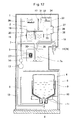
- Fig. 1 shows a water server embodying the present invention.
- the water server includes a casing 1, and a cold water tank 2 and a warm water tank 3 both mounted in the casing 1.
- the water server further includes a container holder 5, an exchangeable raw water container 4 configured to be set in the container holder 5, a raw water supply line 6 through which the raw water container 4 is in communication with the cold water tank 2, and a tank connecting line 7 through which the cold water tank 2 is connected to the warm water tank 3.
- the cold water tank 2 and the warm water tank 3 are vertically aligned with each other with the warm water tank 3 located below the cold water tank 2.
- the raw water container 4 has a water outlet 8 and set in the container holder 5 with the water outlet 8 facing downward.
- the raw water container 4 has a flexible trunk 9 so that the raw water container 4 is gradually collapsible as the water remaining in the container 4 decreases.
- the raw water container 4 can be formed by blow-molding e.g. polyethylene terephthalate (PET) resin or polyethylene (PE) resin.
- PET polyethylene terephthalate
- PE polyethylene
- the container holder 5 is mounted on a slide table 10 horizontally slidably supported by the casing 1 such that the container holder 5 can be slid into and out of the casing 1.
- the container holder 5 is provided with a joint member 11 configured to be detachably connected to the water outlet 8 of the raw water container 4 when the raw water container 4 is set in the container holder 5.
- the joint member 11 is a vertically extending hollow tubular member.
- the raw water supply line 6 is connected at its first end which is closer to the raw water container 4 to the bottom end of the joint member 11.
- the water server further includes an air intake line 12 through which air can be introduced into the raw water container 4.
- the air intake line 12 is also connected, at its first end which is closer to the raw water container 4, to the bottom end of the joint member 11.
- a pump 13 and a flow rate sensor 14 are mounted to an intermediate portion of the raw water supply line 6.
- the pump 13 is a gear pump including a pair of gears meshing with each other and configured to feed drinking water by rotating the gears.
- a diaphragm pump may be used instead which includes a diaphragm and is configured to draw and discharge drinking water by reciprocating the diaphragm.
- a cooling device 15 is mounted to the cold water tank 2 which is configured to cool drinking water stored in the cold water tank 2.
- a baffle plate 16 is provided in the cold water tank 2 which divides the interior of the cold water tank 2 into upper and lower spaces.
- the cooling device 15 is provided on the outer periphery of the cold water tank 2 at its lower portion, and configured to keep drinking water at the portion of the interior of the cold water tank 2 below the baffle plate 16 at a low temperature (about 5°C).
- the cold water tank 2 is provided with a water level sensor 17 which detects the level of drinking water stored in the cold water tank 2.
- the pump 13 is activated to supply water into the cold water tank 2 from the raw water container 4.
- the baffle plate 16 prevents low-temperature drinking water that has been cooled by the cooling device 15 and has collected at the lower portion of the cold water tank 2 from being stirred by normal-temperature drinking water that has been supplied into the cold water tank 2 from the raw water container 4.
- a cold water discharge line 18 is connected to the bottom surface of the cold water tank 2 through which low-temperature drinking water at the lower portion of the cold water tank 2 can be discharged to the outside.
- the cold water discharge line 18 carries a cold water cock 19 which is operable from outside the casing 1. By opening the cold water cock 19, low-temperature drinking water can be discharged from the cold water tank 2 into e.g. a cup.
- the capacity of the cold water tank 2 is smaller than that of the raw water container 4 and is about 2 to 4 liters.
- the cold water tank 2 and the warm water tank 3 are connected together through a tank connecting line 7 having a top end open at the center of the baffle plate 16.
- the tank connecting line 7 extends vertically in a straight line between the bottom surface of the cold water tank 2 and the top surface of the warm water tank 3.
- the tank connecting line 7 has an end portion located in the cold water tank 2, which extends through the bottom of the cold water tank 2 and then upwardly in the cold water tank 2, and is connected to the baffle plate 16.
- a check valve 20 is provided at this end portion which allows drinking water to flow from the cold water tank 2 toward the warm water tank 3 and restrains drinking water from flowing from the warm water tank 3 toward the cold water tank 2.
- the check valve 20 includes a vertically extending hollow tubular valve sleeve 21, a valve body 22 vertically movably received in the valve sleeve 21, a valve seat 23 provided over the valve body 22, and a retainer 24 which restricts the downward stroke of the valve body 22.
- the valve sleeve 21 is inserted in and fixed to the end of the tank connecting line 7 which opens to the center of the baffle plate 16.
- the valve seat 23 has at its center a valve hole 25 extending vertically therethrough.
- the valve seat 23 is a flange portion radially inwardly extending from the valve sleeve 21.
- the valve hole 25 is defined by a circular edge and thus circular in shape.
- the valve body 22 is made of a resin having a lower specific gravity than drinking water (such as polypropylene (PP) resin) so as to float on drinking water.
- PP polypropylene
- the valve body 22 is spherically shaped so that the valve body 22 can stably close the valve hole 25 when the valve body 22 is moved upward in the valve sleeve 21, irrespective of its orientation.
- the valve body 22 has a diameter larger than that of the valve hole 25.
- valve body 22 moves away from the valve seat 23 and opens the valve hole 25, thus allowing drinking water to flow from the upper side to the lower side.
- the valve body 22 is pressed against the valve seat 23, so that the valve hole 25 remains closed, preventing drinking water from flowing from the lower side to the upper side.
- the check valve 20 has no spring for biasing the valve body 22 from the open position toward the closed position.
- the valve body 22 moves downward and away from the valve seat 23 by gravity, thus opening the valve hole 25. This means that when there is no drinking water in the valve sleeve 21, air is allowed to pass through the check valve 20 from under to over the check valve 20.
- the retainer 24 comprises a single rod extending diametrically across the valve sleeve 21.
- the two flow surface areas divided by such a retainer 24 are both sufficiently large, so that the surface tension of water has little influence on the flow of air around the retainer 24 when drinking water and air flow through the check valve 20.
- the valve seat 23 is formed with a communication passage 26 through which the region above the valve seat 23 (region communicating with the cold water tank 2) is in communication with the region below the valve seat 23 (region communicating with the warm water tank 3), with the valve hole 25 closed by the valve body 22.
- the communication passage 26 is a hole vertically extending through the valve seat 23 at a position spaced from the valve hole 25.
- the communication passage 26 has a flow area smaller than the area of the opening of the valve hole 25.
- the warm water tank 3 is filled with drinking water.
- a heater 27 is mounted to the warm water tank 3 to heat drinking water in the warm water tank 3, thereby keeping drinking water in the warm water tank 3 at high temperature (about 90°C).
- the heater 27 shown is a sheath heater, but the heater according to the present invention may be a band heater.
- the sheath heater includes a metal pipe in which is mounted a heating wire configured to heat up when energized, and is mounted to the warm water tank 3 to extend through the peripheral wall of the tank 3 into the tank 3.
- a band heater is a cylindrical heating member in which is embedded a heating wire which heats up when energized. If a band heater is used as the heater 27, it is mounted on the outer periphery of the warm water tank 3 so as to be in close contact with the tank 3.
- a warm water discharge line 28 is connected to the top surface of the warm water tank 3 so that high-temperature drinking water that has collected at the upper portion of the warm water tank 3 can be discharged to the outside through the warm water discharge line 28.
- the warm water discharge line 28 carries a warm water cock 29 which can be operated from outside the casing 1 so that by opening the cock 29, high-temperature drinking water in the warm water tank 3 can be discharged into e.g. a cup. Every time drinking water is discharged from the warm water tank 3, the same amount of drinking water as the water discharged flows from the cold water tank 2 into the warm water tank 3 through the tank connecting line 7, so that the warm water tank 3 is completely filled with water at all times.
- the warm water tank 3 has a capacity of about 1 to 2 liters.
- the tank connecting line 7 includes an in-tank pipe 7a extending from the top surface of the warm water tank 3 downwardly through the interior of the warm water tank 3.
- the in-tank pipe 7a has an open bottom end located in the vicinity of the bottom surface of the warm water tank 3 (at a location upwardly spaced from the inner bottom surface of the warm water tank 3 by not more than 30 mm). This arrangement prevents high-temperature drinking water heated by the heater 27 and flowing upward from directly flowing into the open bottom end of the in-tank pipe 7a.
- a small hole 30 is formed in the in-tank pipe 7a at its portion in the vicinity of the top surface of the warm water tank 3.
- the small hole 30 is arranged such that its peripheral edge is at least partially downwardly spaced from the inner top surface of the warm water tank 3 by not more than 10 mm.
- the small hole 30 has an opening area smaller than the cross-sectional area of the interior of the in-tank pipe 7a.
- the small hole 30 may be a circular hole with a diameter of 2-4 mm.
- the tank connecting line 7 has a small inner diameter in order to reduce convection of drinking water in the tank connecting line 7 due to the difference in temperature between the cold water tank 2 and the warm water tank 3.
- the inner diameter of the tank connecting line 7 is preferably set at 9 mm or larger, more preferably at 10 mm or larger, for the following reasons.
- the inner diameter of the tank connecting line 7 is 8 mm or smaller, when drinking water is introduced from the cold water tank 2 into the warm water tank 3 through the tank connecting line 7, it becomes more difficult to feed air in the warm water tank 3 into the tank connecting line 7, due to the increased influence of surface tension of water. This could make it impossible to discharge air in the warm water tank 3 into the cold water tank 2 through the tank connecting line 7.
- the inner diameter of the tank connecting line 7 is set at 9 mm or larger (preferably 10 mm or larger), since the influence of surface tension of water in the tank connecting line 7 decreases, when drinking water is introduced into the now empty warm water tank 3 from the cold water tank 2 through the tank connecting line 7, air in the warm water tank 3 can smoothly flow into the tank connecting line 7, which in turn makes it possible to smoothly discharge air in the warm water tank 3 through the tank connecting line 7. If, however, the tank connecting line 7 is too large in diameter, this tends to push up the manufacturing cost of the water server.
- the inner diameter of the tank connecting line 7 is therefore limited to 40 mm or less.
- An air sterilizing chamber 32 is connected to the cold water tank 2 through an air introducing line 31.
- the air sterilizing chamber 32 comprises a hollow case 34 formed with an air intake port 33, and an ozone generator 35 mounted in the case 34.
- the ozone generator 35 may be a low-pressure mercury lamp capable of converting oxygen in the air into ozone by irradiating the oxygen with ultraviolet light, or may be a silent discharge device capable of converting oxygen between a pair of electrodes covered with insulating material into ozone by applying an AC voltage between the electrodes.
- the ozone generator 35 of the air sterilizing chamber 32 is configured to be energized and generate ozone at predetermined time intervals such that the case 34 is always filled with ozone.
- the air introducing line 31 is configured such that when the water level in the cold water tank 2 decreases, air can be correspondingly introduced into the cold water tank 2 through the air introducing line 31, thereby keeping the interior of the cold water tank 2 at the atmospheric pressure. Since air thus introduced into the cold water tank 2 has passed through the air sterilizing chamber 32 and has been sterilized by ozone, air in the cold water tank 2 is kept clean.
- a diffusing plate 36 is mounted in the cold water tank 2 which diffuses drinking water discharged from the raw water supply line 6 before reaching the surface of drinking water which is already stored in the cold water tank 2.
- the diffusing plate 36 increases the surface area of drinking water discharged from the raw water supply line 6 that is brought into contact with ozone in the air in the cold water tank 2 (which has been fed into the cold water tank 2 from the air sterilizing chamber 32), thereby improving the hygienic quality of drinking water flowing into the cold water tank 2.
- An ozone generating device 37 is connected to the end of the air intake line 12 remote from the raw water container 4.
- the ozone generating device 37 comprises a hollow case 38 having an inlet and an outlet, and an ozone generator 39 mounted in the case 38.
- the inlet of the case 38 is connected to the air introducing line 31, while the outlet of the case 38 is connected to the air intake line 12.
- the ozone generator 39 may be a low-pressure mercury lamp capable of converting oxygen in the air into ozone by irradiating the oxygen with ultraviolet light, or may be a silent discharge device capable of converting oxygen between a pair of electrodes covered with insulating material into ozone by applying an AC voltage between the electrodes.
- the ozone generating device 37 is operatively associated with the pump 13 so as to generate ozone while the pump 13 is activated.
- the raw water supply line 6 and the air intake line 12 are made of a flexible and ozone-resistant material so that the slide table 10, which supports the container holder 5, can slide in the intended manner and so that ozone generated in the ozone generating device 37 can flow through the lines 6 and 12.
- the raw water supply line 6 and the air intake line 12 may comprise silicon tubes, fluororesin tubes, or fluororubber tubes.
- the cold water tank 2 and the warm water tank 3 are left empty before the water server is placed in the intended use location (in a private home, office, hospital, etc.).
- the valve body 22 is separated downwardly by gravity from the valve hole 25, keeping the valve hole 25 open. Air can thus flow through the check valve 20 from under the check valve (its side facing the warm water tank 3) to over the check valve (its side facing the cold water tank 2).
- an exchangeable raw water container 4 is connected to the water server.
- the water server is then connected to a power source to activate the pump 13, thereby introducing drinking water in the raw water container 4 into the cold water tank 2.
- the water level in the cold water tank 2 thus rises, so that excess air in the cold water tank 2 is expelled to the outside through the air introducing line 31 and then the air sterilizing chamber 32.
- the water level in the cold water tank 2 exceeds the level of the baffle plate 16 (namely, the level of the tank connecting line 7 facing the cold water tank 2)
- drinking water in the cold water tank 2 is introduced into the warm water tank 3 through the tank connecting line 7.
- air in the warm water tank 3 flows into the tank connecting line 7 through the small hole 30, which is formed in the in-tank pipe 7a at its portion in the vicinity of the top surface of the warm water tank 3, and is discharged through the tank connecting line 7 into the cold water tank 2. That is, drinking water in the cold water tank 2 flows through the tank connecting line 7 and is introduced into the empty warm water tank 3 by replacing air in the warm water tank 3.
- the pump 13 When, thereafter, the water level in the cold water tank 2 reaches a predetermined upper limit shown in Fig. 1 , the pump 13 is deactivated. In this state, drinking water in the cold water tank 2 is cooled and kept at a low temperature by the cooling device 15, while drinking water in the warm water tank 3 is heated and kept at a high temperature by the heater 27. While drinking water filling the warm water tank 3 is thermally expanded when heated from normal to high temperature by the heater 27, since, in this state, pressure in the warm water tank 3 is released into the cold water tank 2 through the communication passage 26, the warm water tank 3 is protected against cracks and deformation due to thermal expansion of drinking water.
- the warm water tank 3 Since the warm water tank 3 is located below the cold water tank 2, and the temperature of drinking water in the warm water tank 3 is higher than the temperature of drinking water in the cold water tank 2, convection of drinking water occurs in the tank connecting line 7, which connects together the cold water tank 2 and the warm water tank 3. If there were not the check valve 20 in the tank connecting line 7, drinking water in the warm water tank 3 could flow into the cold water tank 2 due to convection of drinking water in the tank connecting line 7.
- the check valve 20 prevents drinking water in the warm water tank 3 from flowing into the cold water tank 2 due to convection in the tank connecting line 7, thereby preventing loss of energy both in the cold water tank 2 and the warm water tank 3.
- the region above the valve seat 23, i.e. the region communicating with the cold water tank 2 is in communication with the region below valve seat 23, i.e. the region communicating with the warm water tank 3, through the communication passage 26.
- the flow area of the communication passage 26 is significantly small compared to the flow area of the tank connecting line 7, drinking water in the warm water tank 3 scarcely flows into the cold water tank 2 through the communication passage 26.
- a user of the water server discharges low-temperature drinking water in the cold water tank 2 into e.g. a cup by operating the cold water cock 19, the water level in the cold water tank 2 falls.
- the user discharges high-temperature drinking water in the warm water tank 3 into e.g. a cup by operating the warm water cock 29, too, since the same amount of drinking water as the drinking water discharged is introduced into the warm water tank 3 from the cold water tank 2 through the tank connecting line 7, the water level in the cold water tank 2 falls.
- the water level sensor 17 detects that the water level in the cold water tank 2 drops below a predetermined lower limit
- the pump 13 is activated to supply drinking water in the raw water container 4 into the cold water tank 2 as shown in Fig. 10 .
- the ozone generating device 37 is activated to generate ozone.
- the pump 13 and the ozone generating device 37 are configured to be continuously operated for a predetermined time period from this point of time.
- ozone generated by the ozone generating device 37 flows through the air intake line 12 and then through the joint member 11 into the lower portion of the raw water container 4, and then from the lower portion of the raw water container 4, ozone flows through the joint member 11 and then through the raw water supply line 6 into the cold water tank 2.
- valve body 22 of the check valve 20 moves downwardly by gravity, thus opening the valve hole 25.
- This allows passage of air through the check valve 20 from the side of the warm water tank 3 to the side of the cold water tank 2.
- This makes it possible to discharge air in the warm water tank 3 into the cold water tank 2 through the tank connecting line 7 when drinking water is introduced into the empty warm water tank 3.
- it is possible to introduce drinking water in the cold water tank 2 into the warm water tank 3 even while the warm water cock 29 is closed, which in turn prevents the warm water tank 3 from being heated with no water in the tank 3.
- valve body 22 of the check valve 20 When the interior of the valve sleeve 21 of the check valve 20 becomes filled with drinking water, the valve body 22 of the check valve 20 is moved up due to buoyancy, thereby closing the valve hole 25. Thus, once the warm water tank 3 is filled with high-temperature drinking water, it is possible to prevent drinking water in the warm water tank 3 from flowing into the cold water tank 2 due to convection in the tank connecting line 7.
- the check valve 20 of this water server is provided with the communication passage 26, the valve body 22 of the check valve 20 is prevented from being pressed against the valve seat 23 when drinking water is introduced into the empty warm water tank 3. This makes it possible to introduce drinking water into the warm water tank 3 in a stable manner.
- the in-tank pipe 7a is formed with the small hole 30 at its portion near the top surface of the warm water tank 3 such that the interior and the exterior of the pipe 7a communicate with each other, when drinking water is introduced into the empty warm water tank 3 and the water level in the tank 3 increases, it is possible to smoothly discharge air in the warm water tank 3 through the tank connecting line 7.
- this water server is configured such that the ozone generating device 37 generates ozone while the pump 13 is activated, ozone generated by the ozone generating device 37 flows through the air intake line 12, thereby sterilizing the interior of the air intake line 12, when air flows through the air intake line 12 into the raw water container 4. This prevents growth of bacteria in the air intake line 12, and thus keeps the interior of the air intake line 12 in hygienic conditions.
- This water server is further configured such that after drinking water in the raw water container 4 has run out, the pump 13 is continuously activated to allow ozone to be fed through the air intake line 12 and the raw water supply line 6. This means that every time an exchangeable raw water container 4 becomes empty, both the air intake line 12 and the raw water supply line 6 are sterilized with ozone. This keeps the water server in hygienic conditions.
- the raw water container 4 is collapsible as water remaining in the container 4 decreases.
- this invention is also applicable to a water server which uses a raw water container 4 which is not collapsible when water in the container 4 decreases.
- the raw water container 4 of this embodiment has a trunk portion 9 which is of such rigidity as not to be collapsible when water in the container 4 decreases.
- Such a rigid raw water container 4 may be formed by blow-molding e.g. polyethylene terephthalate (PET) resin or polycarbonate (PC) resin.
- the communication passage 26, through which both sides of the valve seat 23 communicate with each other with the valve hole 25 closed by the valve body 22, is a hole extending vertically through the valve seat 23 and spaced from the valve hole 25.
- the communication passage 26 may comprise cutouts formed in the peripheral edge of the valve hole 25.
- the communication passage 26 may comprise at least one groove formed in the outer periphery of the valve sleeve 21 to extend from the top end to the bottom end of the valve sleeve 21.
- the check valve may be configured such that the diameter of the valve body 22 is smaller than the distance S by which the valve body 22 moves vertically from the position where the valve body 22 has moved down by gravity until brought into contact with the retainer 24 when there is no drinking water in the valve sleeve 21 (position shown by solid line) to the position where the valve body 22 is pressed against the valve seat 23, and closes the valve hole 25 (position shown by chain line).
- the water server of the above embodiment is configured such that the warm water tank 3 is provided below the cold water tank 2, the cold water tank 2 and the warm water tank 3 are connected to each other thorough the tank connecting line 7, and the check valve 20 is provided in the tank connecting line 7.
- the tank located above the warm water tank is a cold water tank 2.
- this invention is also applicable to a water server in which the upper tank, i.e. the tank located above the warm water tank 3 is a tank in which water of normal temperature is to be stored.
- the present invention is applicable to a water server which includes a normal temperature tank which is configured to receive and store drinking water from an exchangeable raw water container 4, a cold water tank 2 and a warm water tank 3 which are provided below the normal temperature tank with one of the tanks 2 and 3 on the right-hand side of the other.
- the normal temperature tank is connected to the cold water tank 2 through a cold water tank connecting line, and is connected to the warm water tank 3 through a warm water tank connecting line 7.
- a check valve 20 is provided in the warm water tank connecting line 7 to restrain flow of drinking water from the warm water tank 3 toward the normal temperature tank.
Landscapes
- Engineering & Computer Science (AREA)
- Mechanical Engineering (AREA)
- Devices For Dispensing Beverages (AREA)
Applications Claiming Priority (2)
| Application Number | Priority Date | Filing Date | Title |
|---|---|---|---|
| JP2012066759A JP5647640B2 (ja) | 2012-03-23 | 2012-03-23 | ウォーターサーバー |
| PCT/JP2013/058536 WO2013141399A1 (ja) | 2012-03-23 | 2013-03-25 | ウォーターサーバー |
Publications (2)
| Publication Number | Publication Date |
|---|---|
| EP2829506A1 true EP2829506A1 (de) | 2015-01-28 |
| EP2829506A4 EP2829506A4 (de) | 2016-03-09 |
Family
ID=49222842
Family Applications (1)
| Application Number | Title | Priority Date | Filing Date |
|---|---|---|---|
| EP13764806.9A Withdrawn EP2829506A4 (de) | 2012-03-23 | 2013-03-25 | Wasserservierer |
Country Status (7)
| Country | Link |
|---|---|
| US (1) | US20150048116A1 (de) |
| EP (1) | EP2829506A4 (de) |
| JP (1) | JP5647640B2 (de) |
| KR (1) | KR20140136039A (de) |
| CN (1) | CN104203804A (de) |
| TW (1) | TW201350422A (de) |
| WO (1) | WO2013141399A1 (de) |
Families Citing this family (12)
| Publication number | Priority date | Publication date | Assignee | Title |
|---|---|---|---|---|
| JP6368481B2 (ja) * | 2013-11-14 | 2018-08-01 | Next Innovation合同会社 | 流体収容分配装置 |
| US20150129607A1 (en) * | 2013-11-14 | 2015-05-14 | MTN Products, Inc | Energy saving hot tank for water cooler |
| JP6589229B2 (ja) * | 2014-02-18 | 2019-10-16 | Next Innovation合同会社 | 流体貯留装置 |
| JP5583296B1 (ja) * | 2014-04-15 | 2014-09-03 | 株式会社コスモライフ | ウォーターサーバー |
| JP6005240B1 (ja) * | 2015-10-14 | 2016-10-12 | 株式会社コスモライフ | 鍵付きウォーターサーバー |
| JP2016028970A (ja) * | 2015-10-16 | 2016-03-03 | Next Innovation合同会社 | ウォータサーバの冷水又は温水の貯留装置及び熱伝達体 |
| KR102827320B1 (ko) * | 2016-12-16 | 2025-07-01 | 엘지전자 주식회사 | 정수기 |
| JP7133169B2 (ja) * | 2018-06-26 | 2022-09-08 | 株式会社コスモライフ | ウォーターサーバー |
| DE102018113952B4 (de) * | 2018-07-30 | 2022-01-27 | Danfoss Power Solutions Aps | Hydraulische Lenkeinheit |
| CN109330375B (zh) * | 2018-11-03 | 2020-11-17 | 浙江三宝知识产权服务有限公司 | 一种可自动上水的饮水装置 |
| ES2989640T3 (es) * | 2020-03-02 | 2024-11-27 | Meir Hay Somekh | Dispensador automático de paños de papel húmedos de toalla impregnada de un solo uso |
| US11142444B2 (en) | 2020-03-05 | 2021-10-12 | Wandering Bear Inc. | Refrigerated dispenser conversion system |
Family Cites Families (16)
| Publication number | Priority date | Publication date | Assignee | Title |
|---|---|---|---|---|
| FR1416352A (fr) * | 1964-02-21 | 1965-11-05 | Mac Gregor & Co Naval Architec | Dispositif formant soupape d'évacuation et de non-retour ou analogue et ses diverses applications |
| US3698603A (en) * | 1971-07-09 | 1972-10-17 | Ebco Mfg Co | Water-distributing system for a hot and cold drinking water dispenser |
| JPS5281604U (de) * | 1975-12-15 | 1977-06-17 | ||
| JPS6049281U (ja) * | 1983-09-14 | 1985-04-06 | 岩壺 正道 | 握筒式ポンプにおける逆止弁装置 |
| JPS61141872U (de) * | 1985-02-25 | 1986-09-02 | ||
| JPS62116110U (de) * | 1986-01-14 | 1987-07-23 | ||
| JPS63111391U (de) * | 1987-01-13 | 1988-07-18 | ||
| JPS63318376A (ja) * | 1987-06-23 | 1988-12-27 | Itsusei:Kk | 自動式空気抜弁 |
| JP3400611B2 (ja) * | 1995-06-13 | 2003-04-28 | 株式会社エクセディ | エアブリーザ |
| WO2001038807A1 (en) * | 1999-11-19 | 2001-05-31 | Kabushiki Kaisha Kyusyu Kaihatsu Kikaku | Water heating device for beverage and others and water tank storage container used for the water heating device for beverage and others |
| JP2006347558A (ja) * | 2005-06-13 | 2006-12-28 | Sanden Corp | 飲料ディスペンサ |
| CN2920112Y (zh) * | 2006-07-03 | 2007-07-11 | 于乔治 | 带有热水杀菌系统的桶装水饮水机 |
| CN201131654Y (zh) * | 2007-12-10 | 2008-10-15 | 于乔治 | 饮水机用冷热胆结构 |
| JP5235092B2 (ja) * | 2008-04-11 | 2013-07-10 | 株式会社Osgコーポレーション | 飲料水ディスペンサー |
| US8356731B2 (en) * | 2009-09-09 | 2013-01-22 | Mtn Products Inc | Energy saving baffle for water cooler |
| US20150129607A1 (en) * | 2013-11-14 | 2015-05-14 | MTN Products, Inc | Energy saving hot tank for water cooler |
-
2012
- 2012-03-23 JP JP2012066759A patent/JP5647640B2/ja active Active
-
2013
- 2013-03-25 TW TW102110554A patent/TW201350422A/zh unknown
- 2013-03-25 EP EP13764806.9A patent/EP2829506A4/de not_active Withdrawn
- 2013-03-25 KR KR20147028734A patent/KR20140136039A/ko not_active Withdrawn
- 2013-03-25 WO PCT/JP2013/058536 patent/WO2013141399A1/ja not_active Ceased
- 2013-03-25 US US14/386,865 patent/US20150048116A1/en not_active Abandoned
- 2013-03-25 CN CN201380015275.6A patent/CN104203804A/zh active Pending
Also Published As
| Publication number | Publication date |
|---|---|
| TW201350422A (zh) | 2013-12-16 |
| KR20140136039A (ko) | 2014-11-27 |
| JP5647640B2 (ja) | 2015-01-07 |
| WO2013141399A1 (ja) | 2013-09-26 |
| CN104203804A (zh) | 2014-12-10 |
| EP2829506A4 (de) | 2016-03-09 |
| JP2013199277A (ja) | 2013-10-03 |
| US20150048116A1 (en) | 2015-02-19 |
Similar Documents
| Publication | Publication Date | Title |
|---|---|---|
| EP2829506A1 (de) | Wasserservierer | |
| US9440840B2 (en) | Water dispenser | |
| CN105073629B (zh) | 饮水机 | |
| US20160009537A1 (en) | Water dispenser | |
| US20160016776A1 (en) | Water dispenser | |
| CN104640803B (zh) | 饮水机 | |
| TW201400398A (zh) | 飲水機 | |
| US20150053597A1 (en) | Water dispenser | |
| WO2014061346A1 (ja) | ウォーターサーバー | |
| TWI624632B (zh) | 開飲機 | |
| US20150151957A1 (en) | Water server | |
| CN105189332A (zh) | 饮水机 | |
| CA2798899A1 (en) | Bottom-loading water coolers with ozone sterilizing devices |
Legal Events
| Date | Code | Title | Description |
|---|---|---|---|
| PUAI | Public reference made under article 153(3) epc to a published international application that has entered the european phase |
Free format text: ORIGINAL CODE: 0009012 |
|
| 17P | Request for examination filed |
Effective date: 20141022 |
|
| AK | Designated contracting states |
Kind code of ref document: A1 Designated state(s): AL AT BE BG CH CY CZ DE DK EE ES FI FR GB GR HR HU IE IS IT LI LT LU LV MC MK MT NL NO PL PT RO RS SE SI SK SM TR |
|
| AX | Request for extension of the european patent |
Extension state: BA ME |
|
| DAX | Request for extension of the european patent (deleted) | ||
| RA4 | Supplementary search report drawn up and despatched (corrected) |
Effective date: 20160205 |
|
| RIC1 | Information provided on ipc code assigned before grant |
Ipc: B67D 1/08 20060101ALI20160201BHEP Ipc: B67D 1/14 20060101AFI20160201BHEP Ipc: B67D 3/00 20060101ALI20160201BHEP |
|
| STAA | Information on the status of an ep patent application or granted ep patent |
Free format text: STATUS: THE APPLICATION HAS BEEN WITHDRAWN |
|
| 18W | Application withdrawn |
Effective date: 20160902 |