EP2829777B1 - Kugelventildichtung mit dynamischer C-Dichtung und statischer C-Dichtung - Google Patents
Kugelventildichtung mit dynamischer C-Dichtung und statischer C-Dichtung Download PDFInfo
- Publication number
- EP2829777B1 EP2829777B1 EP14160553.5A EP14160553A EP2829777B1 EP 2829777 B1 EP2829777 B1 EP 2829777B1 EP 14160553 A EP14160553 A EP 14160553A EP 2829777 B1 EP2829777 B1 EP 2829777B1
- Authority
- EP
- European Patent Office
- Prior art keywords
- seal
- seal ring
- ring
- valve body
- valve
- Prior art date
- Legal status (The legal status is an assumption and is not a legal conclusion. Google has not performed a legal analysis and makes no representation as to the accuracy of the status listed.)
- Active
Links
Images


Classifications
-
- F—MECHANICAL ENGINEERING; LIGHTING; HEATING; WEAPONS; BLASTING
- F16—ENGINEERING ELEMENTS AND UNITS; GENERAL MEASURES FOR PRODUCING AND MAINTAINING EFFECTIVE FUNCTIONING OF MACHINES OR INSTALLATIONS; THERMAL INSULATION IN GENERAL
- F16K—VALVES; TAPS; COCKS; ACTUATING-FLOATS; DEVICES FOR VENTING OR AERATING
- F16K5/00—Plug valves; Taps or cocks comprising only cut-off apparatus having at least one of the sealing faces shaped as a more or less complete surface of a solid of revolution, the opening and closing movement being predominantly rotary
- F16K5/06—Plug valves; Taps or cocks comprising only cut-off apparatus having at least one of the sealing faces shaped as a more or less complete surface of a solid of revolution, the opening and closing movement being predominantly rotary with plugs having spherical surfaces; Packings therefor
- F16K5/0663—Packings
- F16K5/0668—Single packings
-
- F—MECHANICAL ENGINEERING; LIGHTING; HEATING; WEAPONS; BLASTING
- F16—ENGINEERING ELEMENTS AND UNITS; GENERAL MEASURES FOR PRODUCING AND MAINTAINING EFFECTIVE FUNCTIONING OF MACHINES OR INSTALLATIONS; THERMAL INSULATION IN GENERAL
- F16K—VALVES; TAPS; COCKS; ACTUATING-FLOATS; DEVICES FOR VENTING OR AERATING
- F16K5/00—Plug valves; Taps or cocks comprising only cut-off apparatus having at least one of the sealing faces shaped as a more or less complete surface of a solid of revolution, the opening and closing movement being predominantly rotary
- F16K5/08—Details
- F16K5/14—Special arrangements for separating the sealing faces or for pressing them together
- F16K5/20—Special arrangements for separating the sealing faces or for pressing them together for plugs with spherical surfaces
- F16K5/205—Sealing effected by the flowing medium
-
- Y—GENERAL TAGGING OF NEW TECHNOLOGICAL DEVELOPMENTS; GENERAL TAGGING OF CROSS-SECTIONAL TECHNOLOGIES SPANNING OVER SEVERAL SECTIONS OF THE IPC; TECHNICAL SUBJECTS COVERED BY FORMER USPC CROSS-REFERENCE ART COLLECTIONS [XRACs] AND DIGESTS
- Y10—TECHNICAL SUBJECTS COVERED BY FORMER USPC
- Y10T—TECHNICAL SUBJECTS COVERED BY FORMER US CLASSIFICATION
- Y10T29/00—Metal working
- Y10T29/49—Method of mechanical manufacture
- Y10T29/49405—Valve or choke making
- Y10T29/49412—Valve or choke making with assembly, disassembly or composite article making
Definitions
- Rotary ball valves are used in a wide number of process control system applications to control some parameters of a process fluid such as a liquid, gas, slurry, etc. While the process control system may use a control valve to ultimately control the pressure, level, pH, or other desired parameter of a fluid, the control valve basically controls the rate of fluid flow.
- WO 2009/032569 discloses a high temperature ball valve seal that achieves Class IV shutoff for operating temperatures above 550 degrees F.
- the ball valve seal includes a C-seal positioned between the main seal and a seal body to prevent fluid from flowing through a secondary flowpath when the ball valve is in a closed position.
- a seal assembly includes a first sealing body, preferably a main seal and a second sealing body, preferably a seal housing). The C-seal and a resilient member connect the main seal to the seal housing.
- Rotary ball valve components including the valve body, the ball element, and the seal assembly, are typically constructed of metal. This stands especially true when used in high pressure and/or high temperature applications.
- the ball element and seal assembly can suffer wear due to the repeated engagement of the ball element and seal assembly during opening and closing of the valve.
- the problems resulting from the wear include, but are not limited to, diminished life span of the valve components, increased frictional forces between the ball element and the seal assembly, and undesirable leakage between the ball element and the seal assembly, as well as between the seal assembly and the valve body.
- the frictional forces tend to increase as the components become more worn, the dynamic performance and control characteristics within the valve are worsened, resulting in inefficiencies and inaccuracies in the valve.
- a first C-seal may be non-slidably disposed on an exterior surface of the seal ring, and the first C-seal may sealingly engage the seal ring and a portion of the valve body to prevent fluid flow through the primary leak path. Moreover, fluid pressure in the first C-seal may bias the seal ring towards the ball element. In addition, a relative displacement between the seal ring and the portion of the valve body may result in a spring force provided by the first C-seal that also biases the seal ring towards the ball element.
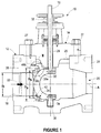
- FIG. 1 depicts a rotary ball valve 10 constructed in accordance with the principles of the disclosure, and generally including a valve body 12, a bonnet 14, a control assembly 16, and a seal assembly 24.
- the valve body 12 has a generally cylindrical shape and includes an inlet portion 18, an outlet portion 20, a primary flowpath 22, and a bonnet opening 25 located adjacent to a top portion of the valve body 12.
- the primary flowpath 22 extends from the inlet portion 18 to the outlet portion 20 in a direction that is generally parallel to a longitudinal axis A.
- the inlet portion 18 is surrounded by an inlet flange 26.
- the outlet portion 20 is surrounded by an outlet flange 28.
- the inlet flange 26 and the outlet flange 28 are adapted to couple the ball valve 10 into a process control pipeline such as by bolting, welding, clamping, or any other known means.
- the ball element 30 typically includes a cammed ball element, as is known in the art, to facilitate a repeatable seal with the seal assembly 24 when in the closed position, as shown in FIG. 1 . More specifically, an exterior surface of the ball element 30 may define a portion of a sphere, wherein all points on the exterior surface of the ball element are not equidistant from a natural pivot point of the ball element, such as the rotational axis of each of the shafts 32, 34.
- the disclosed embodiment of the valve body 12 defines an internal recess 42 disposed completely downstream from the inlet portion 18 of the valve body 12. Said another way, the internal recess 42 is disposed between the inlet portion 18 of the valve body 12 and the ball element 30 of the control assembly 16.
- the recess 42 of the disclosed embodiment is generally annular in shape and has a stepped profile defined by internal surfaces of the valve body 12 including first and second cylindrical surfaces 38a, 38b, and first and second transverse surfaces 40a, 40b.
- the second cylindrical surface 38b is disposed between the inlet portion 18 of the valve body 12 and the first cylindrical surface 38a, when considered relative a direction of the flow path 22 depicted in FIG. 1 .
- the second axial surface 40b is disposed between the inlet portion 18 of the valve body 12 and the first axial surface 40a, when considered relative to the direction of the flowpath 22 depicted in FIG. 1 .
- the first cylindrical surface 38a has a first diameter Da that is larger than a second diameter Db of the second cylindrical surface 38b.
- the first and second diameters Da, Db are each larger than an inlet diameter Di of the inlet portion 18 of the valve body 12.
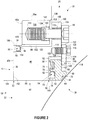
- the seal ring 44 of the seal assembly 24 is generally annular in shape and may be machined from a wear-resistant metal, such as Alloy 6 or stainless steel with Alloy 6 hardfacing, for example. As illustrated in the cross-sectional view of FIG. 2 , the seal ring 44 may be defined laterally by a cylindrical seal inner wall 58 and a cylindrical seal outer wall 60, and a seal top wall 62 may extend from the seal outer wall 60 towards the inner wall 58 in a radial direction.
- a seal ring protrusion 64 may extend from the seal top wall 62, and the seal ring protrusion 64 maybe defined by a cylindrical side protrusion wall 66 that may extend from the seal top wall 62 in an axial direction ( i.e ., a direction parallel to the longitudinal axis A).
- a top protrusion wall 68 may extend from the side protrusion wall 66 in a direction parallel to the seal top wall 62.
- a ball engagement surface 70 may extend between the top protrusion wall 68 and the seal inner wall 58, and the ball engagement surface 70 may be concave in shape.
- the carrier flange 100 may be further defined by a flange top wall 104 that may be parallel to and offset from the flange bottom wall 102.
- a cylindrical flange outer wall 106 may axially extend between the flange bottom wall 102 and the flange top wall 104, and a cylindrical flange inner wall 108 may be radially offset from the flange outer wall 106 and may extend between the flange top wall 104 and the carrier top wall 92. Because the carrier top wall 92 is orthogonal to the flange inside wall 108, a carrier inner recess 110 may be formed that is diagonally opposed to the carrier outer recess 94 of the seal carrier 46.
- a plurality of flange bores 112 may be symmetrically arrayed around the carrier flange 100.
- the flange bores 112 may axially extend from the flange top wall 104 to the flange bottom wall 102.
- Each of the flange bores 112 may have a threaded portion, and each of the flange bores 112 may be adapted to receive a threaded captive bolt 48.
- a plurality of carrier blind bores 114 may be symmetrically arrayed around the seal carrier 46, and each blind bore 114 may axially extend from the flange top wall 104 towards the carrier bottom wall 90.
- Each blind bore 114 may have a threaded portion, and each blind bore 114 may be adapted to receive a cap screw 116.
- a plurality of retainer bores 128 may be symmetrically arrayed around the seal retainer 118, and each retainer bore 128 may axially extend between the retainer top wall 124 and the retainer bottom wall 126.
- each of the retainer bores 128 may be positioned to axially align with a corresponding carrier blind bore 114, and a cap screw 116 may be inserted into each of the retainer bores 128 such that the threaded portion of the cap screw 116 threadedly engages the threaded portion of the carrier blind bore 114, thereby removably securing the seal retainer 118 to the seal carrier 46.
- the seal assembly 24 may also include an annular anchor ring 130 adapted to be secured to the valve body 12.
- the anchor ring 130 may be machined from a corrosion-resistant metal, such as stainless steel, for example.
- the anchor ring 130 may be laterally defined by a cylindrical anchor inner wall 132 and a cylindrical anchor outer wall 134 that each extend in a generally axial direction.
- a planar anchor top wall 136 and a planar anchor bottom wall 138 that is parallel to and axially offset from the anchor top wall 136 may extend in a generally radial direction and may intersect the anchor inner wall 132 and anchor outer wall 134 to further define the anchor ring 130.
- the anchor ring 130 may be secured to the valve body 12 in the internal recess 42 of the valve body 12.
- the anchor outer wall 134 may substantially abut the first cylindrical surface 38a of the internal recess 42, and the anchor bottom wall 138 may substantially abut the first transverse surface 40a of the of the internal recess 42.
- the diameter of the cylindrical anchor inner wall 132 may be slightly greater than the diameter of the second cylindrical surface 38b of the internal recess 42.
- a threaded portion (not shown) of the anchor outer wall 134 may threadedly engage a threaded portion (not shown) of the first cylindrical surface 38a of the valve body 12.
- one or more welds may secure the anchor ring 130 to the valve body 12, or the anchor ring 130 may be secured to the valve body 12 by a combination of a threaded engagement and welding.
- the distal end of the captive bolt 48 is then received into an enlarged diameter portion 142 before threadedly engaging the threaded portion 144 of the anchor bore 140.
- vibrations within the rotary ball valve 10 may cause one or more of the captive bolts 48 to disengage from the threaded portion 144 of the anchor bore 140.
- the captive bolt 48 is prevented from axial displacement through the flange bore 112 of the seal carrier 46 by the threaded portion of the flange bore 112, thereby preventing the captive bolt 48 from falling out of the anchor bore 140 and into the interior of the valve body 12.
- an alignment gap 146 may exist between the seal carrier 46 and the seal ring 44. More specifically, because the diameter of the cylindrical seal outer wall 60 of the seal ring 44 is smaller than the diameter of the cylindrical flange inside wall 108 of the seal carrier, the alignment gap 146 may exist between the surfaces of the seal ring 44 and the seal carrier 46. Due to the alignment gap 146, the seal ring may radially shift relative to the seal carrier 46 when the seal ring 44 is engaged by the ball element 30, thereby allowing the seal ring 44 to radially and axially self-align to compensate for any ball/seal ring 44 misalignments due to machining tolerances to improve the seal between the seal ring 44 and the ball element 30.
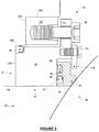
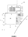
- the diameter of the first cylindrical surface 38a of the valve body 12 may be greater than the diameter of the ring flange wall 342, and the diameter of the second cylindrical surface 38b of the valve body 12 may be greater than the diameter of the ring intermediate wall 336. Accordingly, when the seal assembly 324 is in an assembled state, a seal recess 358 may be created between the ring outer wall 334 and the second cylindrical surface 38b. Additionally, a first alignment gap 360 may exist between the ring intermediate wall 336 and the second cylindrical surface 38b of the valve body 12, and a second alignment gap 362 may exist between the ring flange wall 342 and the first cylindrical surface 38a of the valve body 12.
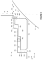
- a first C-seal 330 may be disposed around the circumference of the ring outer wall 334 of the seal ring 326 such that the first C-seal 330 is disposed within the seal recess 358 when the seal assembly 324 is in an assembled state.
- the first C-seal 330 may be fabricated from a corrosion-resistant metal, such as N07718 (Inconel 718).
- first C-seal 330 is disposed within the seal recess 358, process fluid flowing through the primary leak path 328 may enter into the mouth of the first C-seal 330.
- the pressure resulting from the process fluid flowing into the mouth of the first C-seal 330 may provide an axial force on the first C-seal 330 that has a tendency to axially displace the first C-seal 330 towards the outlet portion 20.
Landscapes
- Engineering & Computer Science (AREA)
- General Engineering & Computer Science (AREA)
- Mechanical Engineering (AREA)
- Taps Or Cocks (AREA)
- Valve Housings (AREA)
Claims (4)
- Ventil, umfassend:ein Ventilgehäuse (12) mit einem Einlass (18), einem Auslass (20) und einem Ventilinneren in Fluidkommunikation mit dem Einlass (18) und dem Auslass (20);einen Aufsatz (14), welcher abnehmbar an einem oberen Teil des Ventilgehäuses (12) befestigt ist;ein Kugelelement (30), welches drehbar in dem Ventilinneren montiert ist, wobei eine Außenfläche des Kugelelements einen Teil einer Kugel definiert, wobei nicht alle Punkte auf der Außenfläche des Kugelelements den gleichen Abstand von einem natürlichen Gelenkpunkt des Kugelelements (30) aufweisen;einen Dichtungsring (326), welcher innerhalb des Ventilinneren angeordnet ist und in Richtung des Kugelelements (30) gedrückt wird, wobei der Dichtungsring (326) dafür geeignet ist, abdichtend an das Kugelelement (30) zu greifen und wobei zwischen dem Dichtungsring (326) und dem Ventilgehäuse (12) ein Hauptdurchtrittsweg (328) existiert, wobei der primäre Hauptdurchtrittsweg (50) dem Fluiddruck innerhalb des Ventils ausgesetzt ist; undeine erste C-Dichtung (330), welche nicht-verschiebbar auf einer Außenfläche des Dichtungsrings (326) angeordnet ist, wobei die erste C-Dichtung abdichtend an den Dichtungsring (326) und einen Teil des Ventilgehäuses (12) greift, um einen Fluidfluss durch den Hauptdurchtrittsweg (328) zu verhindern, und wobei der Fluiddruck in der ersten C-Dichtung (330) den Dichtungsring (326) in Richtung des Kugelelements (30) drückt und wobei eine relative Auslenkung zwischen dem Dichtungsring (326) und dem Teil des Ventilgehäuses (12) zu einer durch die erste C-Dichtung (330) ausgeübten Federkraft führt, welche auch den Dichtungsring (326) in Richtung des Kugelelements (30) drückt, wobei die erste C-Dichtung (330) um einen Umfang einer Außenwand (334) eines zylindrischen Rings des Dichtungsrings (326) herum angeordnet ist.
- Ventil nach Anspruch 1, wobei der Dichtungsring (326) in einer inneren Aussparung in einem Innenteil des Ventilgehäuses (12) angeordnet ist und ein Ring, der um einen Teil der inneren Aussparung herum angeordnet ist, die axiale Auslenkung des Dichtungsrings (326) in Richtung des Kugelelements (30) begrenzt.
- Ventil nach Anspruch 1, wobei eine zweite C-Dichtung (364) nicht-verschiebbar auf der Außenfläche des Dichtungsrings angeordnet ist, wobei die zweite C-Dichtung (364) in Nachbarschaft der ersten C-Dichtung (330) angeordnet ist und die zweite C-Dichtung (364) abdichtend an den Dichtungsring (326) und das Ventilgehäuse greift, um einen Fluidfluss durch den Hauptdurchtrittsweg (328) zu verhindern.
- Ventil nach Anspruch 1, wobei zwischen dem Dichtungsring (326) und dem Ventilgehäuse (12) mindestens ein Ausrichtungsspalt (362) ausgebildet ist, wobei der Ausrichtungsspalt (362) einen Teil des Hauptdurchtrittswegs (328) definiert, wobei der Ausrichtungsspalt (362) für einen Raum zwischen dem Dichtungsring (326) und dem Ventilgehäuse (12) sorgt, welcher ermöglicht, dass sich der Dichtungsring (326) radial relativ zu dem Ventilgehäuse (12) bewegt, so dass sich der Dichtungsring (326) selbst ausrichtet, wenn das Kugelelement (30) abdichtend an den Dichtungsring (326) greift.
Applications Claiming Priority (2)
| Application Number | Priority Date | Filing Date | Title |
|---|---|---|---|
| US12/771,950 US8720854B2 (en) | 2010-04-30 | 2010-04-30 | Floating ball valve seal with dynamic C-seal and static C-seal |
| EP11716774.2A EP2564096B1 (de) | 2010-04-30 | 2011-04-18 | Kugelventildichtung mit dynamischer c-dichtung und statischer c-dichtung |
Related Parent Applications (2)
| Application Number | Title | Priority Date | Filing Date |
|---|---|---|---|
| EP11716774.2A Division EP2564096B1 (de) | 2010-04-30 | 2011-04-18 | Kugelventildichtung mit dynamischer c-dichtung und statischer c-dichtung |
| PCT/US2011/032915 Previously-Filed-Application WO2011136968A1 (en) | 2010-04-30 | 2011-04-18 | Ball valve seal with dynamic c-seal and static c-seal |
Publications (2)
| Publication Number | Publication Date |
|---|---|
| EP2829777A1 EP2829777A1 (de) | 2015-01-28 |
| EP2829777B1 true EP2829777B1 (de) | 2016-04-13 |
Family
ID=44140901
Family Applications (2)
| Application Number | Title | Priority Date | Filing Date |
|---|---|---|---|
| EP14160553.5A Active EP2829777B1 (de) | 2010-04-30 | 2011-04-18 | Kugelventildichtung mit dynamischer C-Dichtung und statischer C-Dichtung |
| EP11716774.2A Active EP2564096B1 (de) | 2010-04-30 | 2011-04-18 | Kugelventildichtung mit dynamischer c-dichtung und statischer c-dichtung |
Family Applications After (1)
| Application Number | Title | Priority Date | Filing Date |
|---|---|---|---|
| EP11716774.2A Active EP2564096B1 (de) | 2010-04-30 | 2011-04-18 | Kugelventildichtung mit dynamischer c-dichtung und statischer c-dichtung |
Country Status (10)
| Country | Link |
|---|---|
| US (1) | US8720854B2 (de) |
| EP (2) | EP2829777B1 (de) |
| CN (1) | CN102939486B (de) |
| AU (2) | AU2011245603B2 (de) |
| BR (1) | BR112012027779A2 (de) |
| CA (1) | CA2797862C (de) |
| MX (1) | MX2012012694A (de) |
| NO (1) | NO340207B1 (de) |
| RU (1) | RU2563791C2 (de) |
| WO (1) | WO2011136968A1 (de) |
Families Citing this family (28)
| Publication number | Priority date | Publication date | Assignee | Title |
|---|---|---|---|---|
| WO2010109623A1 (ja) * | 2009-03-26 | 2010-09-30 | 株式会社栗本鐵工所 | 粉体用バルブ |
| US9982789B2 (en) | 2009-12-07 | 2018-05-29 | Cameron International Corporation | Self-relieving ball valve seat |
| JP2013199887A (ja) * | 2012-03-26 | 2013-10-03 | Keihin Corp | 排気ガス再循環バルブ |
| US8857792B2 (en) | 2012-05-14 | 2014-10-14 | Fisher Controls International Llc | Seal ring assemblies for use with rotary valves |
| EP2667066B1 (de) * | 2012-05-23 | 2018-01-17 | Cameron International Corporation | Schützende Frontdichtungsanordnung |
| EP2667067A1 (de) * | 2012-05-23 | 2013-11-27 | Cameron International Corporation | Ventil mit adaptivem Frontdichtungsring |
| EP2667068B1 (de) | 2012-05-23 | 2018-02-14 | Cameron International Corporation | Ventil mit konturierter Bohrung zum Ablenken von Partikeln |
| US10197168B1 (en) | 2013-05-31 | 2019-02-05 | Technetics Group Llc | Energized spring seal for a floating valve seat |
| US9140369B2 (en) | 2013-10-15 | 2015-09-22 | Fisher Controls International Llc | Floating ball valve seal |
| CN107110381B (zh) | 2014-11-07 | 2020-02-14 | 世伟洛克公司 | 自动对准的阀密封件 |
| US9879789B2 (en) * | 2014-12-09 | 2018-01-30 | Cameron International Corporation | Ball valve seal |
| EP3040588B1 (de) * | 2014-12-31 | 2017-05-03 | Cameron International Corporation | Doppelkolbenwirkungs-Lippendichtungs-Sitzanordnungen |
| DE102016203070B3 (de) * | 2016-02-26 | 2017-06-01 | Schaeffler Technologies AG & Co. KG | Anschlussstutzen und Wärmemanagementmodul mit einem solchen |
| DE102016216051A1 (de) * | 2016-08-25 | 2018-03-01 | Volkswagen Aktiengesellschaft | Dichtungsanordnung und Ventilanordnung |
| CN106556637A (zh) * | 2016-11-11 | 2017-04-05 | 上海理工大学 | 一种光电催化反应实验装置 |
| RU175005U1 (ru) * | 2016-12-27 | 2017-11-15 | Фукуяма Ко., Лтд | Составной держатель уплотнения с пружинным стопорным кольцом |
| CN111433495B (zh) | 2017-10-10 | 2022-12-30 | 卡梅伦技术有限公司 | 用于球阀的轮廓化集成阀座 |
| US10883641B2 (en) | 2018-03-30 | 2021-01-05 | Vittorio BONOMI | Quick disconnect coupling |
| US12259064B2 (en) | 2018-11-01 | 2025-03-25 | Oil States Energy Services, L.L.C. | Valve with pressure differential seating |
| US11028933B2 (en) * | 2019-01-22 | 2021-06-08 | Emerson Vulcan Holding Llc | Valve seal assembly |
| US11946557B2 (en) | 2020-02-14 | 2024-04-02 | Crane Chempharma & Energy Corp. | Valve with unobstructed flow path having increased flow coefficient |
| US11953113B2 (en) * | 2020-02-14 | 2024-04-09 | Crane Chempharma & Energy Corp. | Valve with unobstructed flow path having increased flow coefficient |
| US11519509B2 (en) | 2020-02-14 | 2022-12-06 | Crane Chempharma & Energy Corp. | Valve with unobstructed flow path having increased flow coefficient |
| US11841089B2 (en) | 2020-02-14 | 2023-12-12 | Crane Chempharma & Energy Corp. | Valve with unobstructed flow path having increased flow coefficient |
| CN115325200A (zh) * | 2022-09-01 | 2022-11-11 | 苏州纽威阀门股份有限公司 | 一种金属密封球阀 |
| US12072042B2 (en) * | 2022-12-14 | 2024-08-27 | Fisher Controls International Llc | Valve seat and a valve sealing arrangement of a valve assembly |
| CN116877723B (zh) * | 2023-07-12 | 2024-08-09 | 替科斯科技集团丽水流体设备有限公司 | 一种c型阀 |
| CN117307739A (zh) * | 2023-09-25 | 2023-12-29 | 欧维克集团有限公司 | 一种阀座组件和角行程旋转阀 |
Family Cites Families (21)
| Publication number | Priority date | Publication date | Assignee | Title |
|---|---|---|---|---|
| DE1266594B (de) | 1959-07-14 | 1968-04-18 | Doering G M B H | Absperrklappe |
| US3218024A (en) * | 1962-07-18 | 1965-11-16 | Sealol | Fluid motor actuated ball valve |
| US3301523A (en) * | 1964-04-17 | 1967-01-31 | Acf Ind Inc | Resilient valve seats with rentenion means |
| FR1511626A (fr) * | 1966-12-19 | 1968-02-02 | Bouvier Ateliers | Vanne sphérique à sièges flottants escamotables |
| US3421733A (en) * | 1967-10-16 | 1969-01-14 | Acf Ind Inc | Valve having pressure actuated seats |
| US3497178A (en) * | 1968-03-21 | 1970-02-24 | Hills Mccanna Co | Ball valve with movable yieldable polymeric seats |
| US3598363A (en) * | 1969-09-04 | 1971-08-10 | Golconda Corp | Ball valve |
| US3726504A (en) * | 1971-04-02 | 1973-04-10 | Gen Signal Corp | Corrosion resistant valving edge for butter-fly valve disc |
| US4084608A (en) * | 1976-07-01 | 1978-04-18 | Constructions Metalliques De Provence | Cocks having rotating valves and sliding seats |
| JPS5825177Y2 (ja) * | 1977-05-30 | 1983-05-30 | 株式会社日本製鋼所 | ボ−ル弁等におけるシ−トリング装置 |
| US4519579A (en) * | 1983-02-14 | 1985-05-28 | Fisher Controls, International, Inc. | Cam valve self-centering seat |
| US4658847A (en) * | 1985-07-09 | 1987-04-21 | The Fluorocarbon Company | Bimetallic C-ring seal |
| FI72584C (fi) | 1985-09-04 | 1987-06-08 | Neles Oy | Ventil. |
| GB8705004D0 (en) * | 1987-03-04 | 1987-04-08 | Hindle Cockburns Ltd | Valves |
| SU1588970A1 (ru) * | 1987-06-19 | 1990-08-30 | А. А. Шишкин | Шаровой пробковый кран А.А.Шишкина |
| DE4034396A1 (de) | 1990-10-29 | 1992-04-30 | Burgmann Dichtungswerk Feodor | Dichtungsanordnung fuer einen kugelhahn |
| US5313976A (en) * | 1993-07-26 | 1994-05-24 | Keystone International Holdings, Corp. | Top entry ball valve and method of assembly |
| US20010045231A1 (en) * | 1999-06-14 | 2001-11-29 | Gilles Monod | Ball valve with replaceable cartridge insert |
| RU2334149C2 (ru) * | 2006-08-09 | 2008-09-20 | Открытое акционерное общество "Волгограднефтемаш" | Шаровой кран |
| US8113484B2 (en) * | 2007-09-06 | 2012-02-14 | Fisher Controls International Llc | High temperature ball valve seal |
| US7690626B2 (en) * | 2007-10-15 | 2010-04-06 | Stunkard Gerald A | Ball valve having self-centering seats |
-
2010
- 2010-04-30 US US12/771,950 patent/US8720854B2/en active Active
-
2011
- 2011-04-18 EP EP14160553.5A patent/EP2829777B1/de active Active
- 2011-04-18 BR BR112012027779A patent/BR112012027779A2/pt not_active Application Discontinuation
- 2011-04-18 WO PCT/US2011/032915 patent/WO2011136968A1/en not_active Ceased
- 2011-04-18 CN CN201180029049.4A patent/CN102939486B/zh active Active
- 2011-04-18 RU RU2012150150/06A patent/RU2563791C2/ru active
- 2011-04-18 MX MX2012012694A patent/MX2012012694A/es active IP Right Grant
- 2011-04-18 CA CA2797862A patent/CA2797862C/en active Active
- 2011-04-18 EP EP11716774.2A patent/EP2564096B1/de active Active
- 2011-04-18 AU AU2011245603A patent/AU2011245603B2/en not_active Ceased
-
2012
- 2012-11-01 NO NO20121285A patent/NO340207B1/no not_active IP Right Cessation
-
2017
- 2017-01-13 AU AU2017200231A patent/AU2017200231B2/en active Active
Also Published As
| Publication number | Publication date |
|---|---|
| BR112012027779A2 (pt) | 2017-08-08 |
| CN102939486B (zh) | 2015-07-29 |
| CN102939486A (zh) | 2013-02-20 |
| EP2564096A1 (de) | 2013-03-06 |
| RU2563791C2 (ru) | 2015-09-20 |
| US8720854B2 (en) | 2014-05-13 |
| AU2017200231B2 (en) | 2018-10-18 |
| AU2011245603B2 (en) | 2016-10-13 |
| EP2829777A1 (de) | 2015-01-28 |
| CA2797862C (en) | 2018-05-15 |
| MX2012012694A (es) | 2012-12-17 |
| RU2012150150A (ru) | 2014-06-10 |
| AU2017200231A1 (en) | 2017-02-02 |
| NO20121285A1 (no) | 2012-11-01 |
| NO340207B1 (no) | 2017-03-20 |
| WO2011136968A1 (en) | 2011-11-03 |
| EP2564096B1 (de) | 2014-03-19 |
| CA2797862A1 (en) | 2011-11-03 |
| US20110266482A1 (en) | 2011-11-03 |
Similar Documents
| Publication | Publication Date | Title |
|---|---|---|
| AU2017200231B2 (en) | Ball valve seal with dynamic C-seal and static C-seal | |
| AU2011245550B2 (en) | Floating ball valve seal with bellows and C-seal | |
| AU2011245603A1 (en) | Ball valve seal with dynamic C-seal and static C-seal | |
| AU2011245550A1 (en) | Floating ball valve seal with bellows and C-seal | |
| US9285039B2 (en) | Sleeve seal assembly and rotary valve having sleeve seal assembly | |
| EP3058256B1 (de) | Dichtung für schwimmendes kugelventil | |
| US8281798B2 (en) | Ball valve seal assembly and ball valve comprising same |
Legal Events
| Date | Code | Title | Description |
|---|---|---|---|
| 17P | Request for examination filed |
Effective date: 20140318 |
|
| AC | Divisional application: reference to earlier application |
Ref document number: 2564096 Country of ref document: EP Kind code of ref document: P |
|
| AK | Designated contracting states |
Kind code of ref document: A1 Designated state(s): AL AT BE BG CH CY CZ DE DK EE ES FI FR GB GR HR HU IE IS IT LI LT LU LV MC MK MT NL NO PL PT RO RS SE SI SK SM TR |
|
| PUAI | Public reference made under article 153(3) epc to a published international application that has entered the european phase |
Free format text: ORIGINAL CODE: 0009012 |
|
| R17P | Request for examination filed (corrected) |
Effective date: 20150724 |
|
| RBV | Designated contracting states (corrected) |
Designated state(s): AL AT BE BG CH CY CZ DE DK EE ES FI FR GB GR HR HU IE IS IT LI LT LU LV MC MK MT NL NO PL PT RO RS SE SI SK SM TR |
|
| RIC1 | Information provided on ipc code assigned before grant |
Ipc: F16K 1/226 20060101ALI20150831BHEP Ipc: F16K 5/06 20060101AFI20150831BHEP |
|
| GRAP | Despatch of communication of intention to grant a patent |
Free format text: ORIGINAL CODE: EPIDOSNIGR1 |
|
| RIN1 | Information on inventor provided before grant (corrected) |
Inventor name: FITZGERALD, WILLIAM V. Inventor name: DALLUGE, PAUL R. Inventor name: DAVIES, LONNIE O. |
|
| INTG | Intention to grant announced |
Effective date: 20151019 |
|
| GRAS | Grant fee paid |
Free format text: ORIGINAL CODE: EPIDOSNIGR3 |
|
| GRAA | (expected) grant |
Free format text: ORIGINAL CODE: 0009210 |
|
| AC | Divisional application: reference to earlier application |
Ref document number: 2564096 Country of ref document: EP Kind code of ref document: P |
|
| AK | Designated contracting states |
Kind code of ref document: B1 Designated state(s): AL AT BE BG CH CY CZ DE DK EE ES FI FR GB GR HR HU IE IS IT LI LT LU LV MC MK MT NL NO PL PT RO RS SE SI SK SM TR |
|
| REG | Reference to a national code |
Ref country code: GB Ref legal event code: FG4D |
|
| REG | Reference to a national code |
Ref country code: AT Ref legal event code: REF Ref document number: 790511 Country of ref document: AT Kind code of ref document: T Effective date: 20160415 Ref country code: CH Ref legal event code: EP |
|
| REG | Reference to a national code |
Ref country code: FR Ref legal event code: PLFP Year of fee payment: 6 |
|
| REG | Reference to a national code |
Ref country code: IE Ref legal event code: FG4D |
|
| REG | Reference to a national code |
Ref country code: DE Ref legal event code: R096 Ref document number: 602011025407 Country of ref document: DE |
|
| REG | Reference to a national code |
Ref country code: LT Ref legal event code: MG4D |
|
| PG25 | Lapsed in a contracting state [announced via postgrant information from national office to epo] |
Ref country code: BE Free format text: LAPSE BECAUSE OF NON-PAYMENT OF DUE FEES Effective date: 20160430 |
|
| REG | Reference to a national code |
Ref country code: AT Ref legal event code: MK05 Ref document number: 790511 Country of ref document: AT Kind code of ref document: T Effective date: 20160413 |
|
| REG | Reference to a national code |
Ref country code: NL Ref legal event code: MP Effective date: 20160413 |
|
| PG25 | Lapsed in a contracting state [announced via postgrant information from national office to epo] |
Ref country code: NL Free format text: LAPSE BECAUSE OF FAILURE TO SUBMIT A TRANSLATION OF THE DESCRIPTION OR TO PAY THE FEE WITHIN THE PRESCRIBED TIME-LIMIT Effective date: 20160413 Ref country code: FI Free format text: LAPSE BECAUSE OF FAILURE TO SUBMIT A TRANSLATION OF THE DESCRIPTION OR TO PAY THE FEE WITHIN THE PRESCRIBED TIME-LIMIT Effective date: 20160413 Ref country code: NO Free format text: LAPSE BECAUSE OF FAILURE TO SUBMIT A TRANSLATION OF THE DESCRIPTION OR TO PAY THE FEE WITHIN THE PRESCRIBED TIME-LIMIT Effective date: 20160713 Ref country code: LT Free format text: LAPSE BECAUSE OF FAILURE TO SUBMIT A TRANSLATION OF THE DESCRIPTION OR TO PAY THE FEE WITHIN THE PRESCRIBED TIME-LIMIT Effective date: 20160413 Ref country code: PL Free format text: LAPSE BECAUSE OF FAILURE TO SUBMIT A TRANSLATION OF THE DESCRIPTION OR TO PAY THE FEE WITHIN THE PRESCRIBED TIME-LIMIT Effective date: 20160413 |
|
| REG | Reference to a national code |
Ref country code: DE Ref legal event code: R119 Ref document number: 602011025407 Country of ref document: DE |
|
| PG25 | Lapsed in a contracting state [announced via postgrant information from national office to epo] |
Ref country code: AT Free format text: LAPSE BECAUSE OF FAILURE TO SUBMIT A TRANSLATION OF THE DESCRIPTION OR TO PAY THE FEE WITHIN THE PRESCRIBED TIME-LIMIT Effective date: 20160413 Ref country code: RS Free format text: LAPSE BECAUSE OF FAILURE TO SUBMIT A TRANSLATION OF THE DESCRIPTION OR TO PAY THE FEE WITHIN THE PRESCRIBED TIME-LIMIT Effective date: 20160413 Ref country code: SE Free format text: LAPSE BECAUSE OF FAILURE TO SUBMIT A TRANSLATION OF THE DESCRIPTION OR TO PAY THE FEE WITHIN THE PRESCRIBED TIME-LIMIT Effective date: 20160413 Ref country code: LV Free format text: LAPSE BECAUSE OF FAILURE TO SUBMIT A TRANSLATION OF THE DESCRIPTION OR TO PAY THE FEE WITHIN THE PRESCRIBED TIME-LIMIT Effective date: 20160413 Ref country code: PT Free format text: LAPSE BECAUSE OF FAILURE TO SUBMIT A TRANSLATION OF THE DESCRIPTION OR TO PAY THE FEE WITHIN THE PRESCRIBED TIME-LIMIT Effective date: 20160816 Ref country code: ES Free format text: LAPSE BECAUSE OF FAILURE TO SUBMIT A TRANSLATION OF THE DESCRIPTION OR TO PAY THE FEE WITHIN THE PRESCRIBED TIME-LIMIT Effective date: 20160413 Ref country code: GR Free format text: LAPSE BECAUSE OF FAILURE TO SUBMIT A TRANSLATION OF THE DESCRIPTION OR TO PAY THE FEE WITHIN THE PRESCRIBED TIME-LIMIT Effective date: 20160714 Ref country code: HR Free format text: LAPSE BECAUSE OF FAILURE TO SUBMIT A TRANSLATION OF THE DESCRIPTION OR TO PAY THE FEE WITHIN THE PRESCRIBED TIME-LIMIT Effective date: 20160413 |
|
| REG | Reference to a national code |
Ref country code: CH Ref legal event code: PL |
|
| PG25 | Lapsed in a contracting state [announced via postgrant information from national office to epo] |
Ref country code: BE Free format text: LAPSE BECAUSE OF FAILURE TO SUBMIT A TRANSLATION OF THE DESCRIPTION OR TO PAY THE FEE WITHIN THE PRESCRIBED TIME-LIMIT Effective date: 20160413 Ref country code: IT Free format text: LAPSE BECAUSE OF FAILURE TO SUBMIT A TRANSLATION OF THE DESCRIPTION OR TO PAY THE FEE WITHIN THE PRESCRIBED TIME-LIMIT Effective date: 20160413 |
|
| REG | Reference to a national code |
Ref country code: IE Ref legal event code: MM4A |
|
| PG25 | Lapsed in a contracting state [announced via postgrant information from national office to epo] |
Ref country code: DE Free format text: LAPSE BECAUSE OF NON-PAYMENT OF DUE FEES Effective date: 20161101 Ref country code: CH Free format text: LAPSE BECAUSE OF NON-PAYMENT OF DUE FEES Effective date: 20160430 Ref country code: SK Free format text: LAPSE BECAUSE OF FAILURE TO SUBMIT A TRANSLATION OF THE DESCRIPTION OR TO PAY THE FEE WITHIN THE PRESCRIBED TIME-LIMIT Effective date: 20160413 Ref country code: EE Free format text: LAPSE BECAUSE OF FAILURE TO SUBMIT A TRANSLATION OF THE DESCRIPTION OR TO PAY THE FEE WITHIN THE PRESCRIBED TIME-LIMIT Effective date: 20160413 Ref country code: CZ Free format text: LAPSE BECAUSE OF FAILURE TO SUBMIT A TRANSLATION OF THE DESCRIPTION OR TO PAY THE FEE WITHIN THE PRESCRIBED TIME-LIMIT Effective date: 20160413 Ref country code: LI Free format text: LAPSE BECAUSE OF NON-PAYMENT OF DUE FEES Effective date: 20160430 Ref country code: RO Free format text: LAPSE BECAUSE OF FAILURE TO SUBMIT A TRANSLATION OF THE DESCRIPTION OR TO PAY THE FEE WITHIN THE PRESCRIBED TIME-LIMIT Effective date: 20160413 Ref country code: MC Free format text: LAPSE BECAUSE OF FAILURE TO SUBMIT A TRANSLATION OF THE DESCRIPTION OR TO PAY THE FEE WITHIN THE PRESCRIBED TIME-LIMIT Effective date: 20160413 Ref country code: DK Free format text: LAPSE BECAUSE OF FAILURE TO SUBMIT A TRANSLATION OF THE DESCRIPTION OR TO PAY THE FEE WITHIN THE PRESCRIBED TIME-LIMIT Effective date: 20160413 |
|
| PLBE | No opposition filed within time limit |
Free format text: ORIGINAL CODE: 0009261 |
|
| STAA | Information on the status of an ep patent application or granted ep patent |
Free format text: STATUS: NO OPPOSITION FILED WITHIN TIME LIMIT |
|
| PG25 | Lapsed in a contracting state [announced via postgrant information from national office to epo] |
Ref country code: SM Free format text: LAPSE BECAUSE OF FAILURE TO SUBMIT A TRANSLATION OF THE DESCRIPTION OR TO PAY THE FEE WITHIN THE PRESCRIBED TIME-LIMIT Effective date: 20160413 |
|
| 26N | No opposition filed |
Effective date: 20170116 |
|
| REG | Reference to a national code |
Ref country code: FR Ref legal event code: PLFP Year of fee payment: 7 |
|
| PG25 | Lapsed in a contracting state [announced via postgrant information from national office to epo] |
Ref country code: IE Free format text: LAPSE BECAUSE OF NON-PAYMENT OF DUE FEES Effective date: 20160418 Ref country code: SI Free format text: LAPSE BECAUSE OF FAILURE TO SUBMIT A TRANSLATION OF THE DESCRIPTION OR TO PAY THE FEE WITHIN THE PRESCRIBED TIME-LIMIT Effective date: 20160413 |
|
| REG | Reference to a national code |
Ref country code: FR Ref legal event code: PLFP Year of fee payment: 8 |
|
| PG25 | Lapsed in a contracting state [announced via postgrant information from national office to epo] |
Ref country code: HU Free format text: LAPSE BECAUSE OF FAILURE TO SUBMIT A TRANSLATION OF THE DESCRIPTION OR TO PAY THE FEE WITHIN THE PRESCRIBED TIME-LIMIT; INVALID AB INITIO Effective date: 20110418 |
|
| PG25 | Lapsed in a contracting state [announced via postgrant information from national office to epo] |
Ref country code: MT Free format text: LAPSE BECAUSE OF NON-PAYMENT OF DUE FEES Effective date: 20160430 Ref country code: LU Free format text: LAPSE BECAUSE OF NON-PAYMENT OF DUE FEES Effective date: 20160418 Ref country code: IS Free format text: LAPSE BECAUSE OF FAILURE TO SUBMIT A TRANSLATION OF THE DESCRIPTION OR TO PAY THE FEE WITHIN THE PRESCRIBED TIME-LIMIT Effective date: 20160413 Ref country code: CY Free format text: LAPSE BECAUSE OF FAILURE TO SUBMIT A TRANSLATION OF THE DESCRIPTION OR TO PAY THE FEE WITHIN THE PRESCRIBED TIME-LIMIT Effective date: 20160413 Ref country code: MK Free format text: LAPSE BECAUSE OF FAILURE TO SUBMIT A TRANSLATION OF THE DESCRIPTION OR TO PAY THE FEE WITHIN THE PRESCRIBED TIME-LIMIT Effective date: 20160413 |
|
| PG25 | Lapsed in a contracting state [announced via postgrant information from national office to epo] |
Ref country code: BG Free format text: LAPSE BECAUSE OF FAILURE TO SUBMIT A TRANSLATION OF THE DESCRIPTION OR TO PAY THE FEE WITHIN THE PRESCRIBED TIME-LIMIT Effective date: 20160413 |
|
| PG25 | Lapsed in a contracting state [announced via postgrant information from national office to epo] |
Ref country code: AL Free format text: LAPSE BECAUSE OF FAILURE TO SUBMIT A TRANSLATION OF THE DESCRIPTION OR TO PAY THE FEE WITHIN THE PRESCRIBED TIME-LIMIT Effective date: 20160413 Ref country code: TR Free format text: LAPSE BECAUSE OF FAILURE TO SUBMIT A TRANSLATION OF THE DESCRIPTION OR TO PAY THE FEE WITHIN THE PRESCRIBED TIME-LIMIT Effective date: 20160413 |
|
| P01 | Opt-out of the competence of the unified patent court (upc) registered |
Effective date: 20230526 |
|
| PGFP | Annual fee paid to national office [announced via postgrant information from national office to epo] |
Ref country code: GB Payment date: 20260319 Year of fee payment: 16 |
|
| PGFP | Annual fee paid to national office [announced via postgrant information from national office to epo] |
Ref country code: FR Payment date: 20260319 Year of fee payment: 16 |