EP2829792B1 - Lighting device - Google Patents
Lighting device Download PDFInfo
- Publication number
- EP2829792B1 EP2829792B1 EP13787807.0A EP13787807A EP2829792B1 EP 2829792 B1 EP2829792 B1 EP 2829792B1 EP 13787807 A EP13787807 A EP 13787807A EP 2829792 B1 EP2829792 B1 EP 2829792B1
- Authority
- EP
- European Patent Office
- Prior art keywords
- light
- light guide
- disposed
- guide unit
- lighting device
- Prior art date
- Legal status (The legal status is an assumption and is not a legal conclusion. Google has not performed a legal analysis and makes no representation as to the accuracy of the status listed.)
- Not-in-force
Links
Images








Classifications
-
- G—PHYSICS
- G02—OPTICS
- G02B—OPTICAL ELEMENTS, SYSTEMS OR APPARATUS
- G02B6/00—Light guides; Structural details of arrangements comprising light guides and other optical elements, e.g. couplings
- G02B6/0001—Light guides; Structural details of arrangements comprising light guides and other optical elements, e.g. couplings specially adapted for lighting devices or systems
- G02B6/0011—Light guides; Structural details of arrangements comprising light guides and other optical elements, e.g. couplings specially adapted for lighting devices or systems the light guides being planar or of plate-like form
- G02B6/0075—Arrangements of multiple light guides
- G02B6/0078—Side-by-side arrangements, e.g. for large area displays
-
- G—PHYSICS
- G02—OPTICS
- G02B—OPTICAL ELEMENTS, SYSTEMS OR APPARATUS
- G02B6/00—Light guides; Structural details of arrangements comprising light guides and other optical elements, e.g. couplings
- G02B6/0001—Light guides; Structural details of arrangements comprising light guides and other optical elements, e.g. couplings specially adapted for lighting devices or systems
-
- F—MECHANICAL ENGINEERING; LIGHTING; HEATING; WEAPONS; BLASTING
- F21—LIGHTING
- F21S—NON-PORTABLE LIGHTING DEVICES; SYSTEMS THEREOF; VEHICLE LIGHTING DEVICES SPECIALLY ADAPTED FOR VEHICLE EXTERIORS
- F21S8/00—Lighting devices intended for fixed installation
- F21S8/04—Lighting devices intended for fixed installation intended only for mounting on a ceiling or the like overhead structures
- F21S8/06—Lighting devices intended for fixed installation intended only for mounting on a ceiling or the like overhead structures by suspension
- F21S8/061—Lighting devices intended for fixed installation intended only for mounting on a ceiling or the like overhead structures by suspension with a non-rigid pendant, i.e. a cable, wire or chain
-
- F—MECHANICAL ENGINEERING; LIGHTING; HEATING; WEAPONS; BLASTING
- F21—LIGHTING
- F21V—FUNCTIONAL FEATURES OR DETAILS OF LIGHTING DEVICES OR SYSTEMS THEREOF; STRUCTURAL COMBINATIONS OF LIGHTING DEVICES WITH OTHER ARTICLES, NOT OTHERWISE PROVIDED FOR
- F21V15/00—Protecting lighting devices from damage
- F21V15/01—Housings, e.g. material or assembling of housing parts
- F21V15/015—Devices for covering joints between adjacent lighting devices; End coverings
-
- F—MECHANICAL ENGINEERING; LIGHTING; HEATING; WEAPONS; BLASTING
- F21—LIGHTING
- F21V—FUNCTIONAL FEATURES OR DETAILS OF LIGHTING DEVICES OR SYSTEMS THEREOF; STRUCTURAL COMBINATIONS OF LIGHTING DEVICES WITH OTHER ARTICLES, NOT OTHERWISE PROVIDED FOR
- F21V17/00—Fastening of component parts of lighting devices, e.g. shades, globes, refractors, reflectors, filters, screens, grids or protective cages
-
- F—MECHANICAL ENGINEERING; LIGHTING; HEATING; WEAPONS; BLASTING
- F21—LIGHTING
- F21V—FUNCTIONAL FEATURES OR DETAILS OF LIGHTING DEVICES OR SYSTEMS THEREOF; STRUCTURAL COMBINATIONS OF LIGHTING DEVICES WITH OTHER ARTICLES, NOT OTHERWISE PROVIDED FOR
- F21V19/00—Fastening of light sources or lamp holders
- F21V19/001—Fastening of light sources or lamp holders the light sources being semiconductors devices, e.g. LEDs
- F21V19/003—Fastening of light source holders, e.g. of circuit boards or substrates holding light sources
- F21V19/0045—Fastening of light source holders, e.g. of circuit boards or substrates holding light sources by tongue and groove connections, e.g. dovetail interlocking means fixed by sliding
-
- G—PHYSICS
- G02—OPTICS
- G02B—OPTICAL ELEMENTS, SYSTEMS OR APPARATUS
- G02B6/00—Light guides; Structural details of arrangements comprising light guides and other optical elements, e.g. couplings
- G02B6/0001—Light guides; Structural details of arrangements comprising light guides and other optical elements, e.g. couplings specially adapted for lighting devices or systems
- G02B6/0011—Light guides; Structural details of arrangements comprising light guides and other optical elements, e.g. couplings specially adapted for lighting devices or systems the light guides being planar or of plate-like form
- G02B6/0013—Means for improving the coupling-in of light from the light source into the light guide
- G02B6/0015—Means for improving the coupling-in of light from the light source into the light guide provided on the surface of the light guide or in the bulk of it
- G02B6/0016—Grooves, prisms, gratings, scattering particles or rough surfaces
-
- G—PHYSICS
- G02—OPTICS
- G02B—OPTICAL ELEMENTS, SYSTEMS OR APPARATUS
- G02B6/00—Light guides; Structural details of arrangements comprising light guides and other optical elements, e.g. couplings
- G02B6/0001—Light guides; Structural details of arrangements comprising light guides and other optical elements, e.g. couplings specially adapted for lighting devices or systems
- G02B6/0011—Light guides; Structural details of arrangements comprising light guides and other optical elements, e.g. couplings specially adapted for lighting devices or systems the light guides being planar or of plate-like form
- G02B6/0013—Means for improving the coupling-in of light from the light source into the light guide
- G02B6/0015—Means for improving the coupling-in of light from the light source into the light guide provided on the surface of the light guide or in the bulk of it
- G02B6/002—Means for improving the coupling-in of light from the light source into the light guide provided on the surface of the light guide or in the bulk of it by shaping at least a portion of the light guide, e.g. with collimating, focussing or diverging surfaces
- G02B6/0021—Means for improving the coupling-in of light from the light source into the light guide provided on the surface of the light guide or in the bulk of it by shaping at least a portion of the light guide, e.g. with collimating, focussing or diverging surfaces for housing at least a part of the light source, e.g. by forming holes or recesses
-
- G—PHYSICS
- G02—OPTICS
- G02B—OPTICAL ELEMENTS, SYSTEMS OR APPARATUS
- G02B6/00—Light guides; Structural details of arrangements comprising light guides and other optical elements, e.g. couplings
- G02B6/0001—Light guides; Structural details of arrangements comprising light guides and other optical elements, e.g. couplings specially adapted for lighting devices or systems
- G02B6/0011—Light guides; Structural details of arrangements comprising light guides and other optical elements, e.g. couplings specially adapted for lighting devices or systems the light guides being planar or of plate-like form
- G02B6/0033—Means for improving the coupling-out of light from the light guide
- G02B6/005—Means for improving the coupling-out of light from the light guide provided by one optical element, or plurality thereof, placed on the light output side of the light guide
- G02B6/0055—Reflecting element, sheet or layer
-
- F—MECHANICAL ENGINEERING; LIGHTING; HEATING; WEAPONS; BLASTING
- F21—LIGHTING
- F21V—FUNCTIONAL FEATURES OR DETAILS OF LIGHTING DEVICES OR SYSTEMS THEREOF; STRUCTURAL COMBINATIONS OF LIGHTING DEVICES WITH OTHER ARTICLES, NOT OTHERWISE PROVIDED FOR
- F21V3/00—Globes; Bowls; Cover glasses
-
- F—MECHANICAL ENGINEERING; LIGHTING; HEATING; WEAPONS; BLASTING
- F21—LIGHTING
- F21Y—INDEXING SCHEME ASSOCIATED WITH SUBCLASSES F21K, F21L, F21S and F21V, RELATING TO THE FORM OR THE KIND OF THE LIGHT SOURCES OR OF THE COLOUR OF THE LIGHT EMITTED
- F21Y2101/00—Point-like light sources
-
- F—MECHANICAL ENGINEERING; LIGHTING; HEATING; WEAPONS; BLASTING
- F21—LIGHTING
- F21Y—INDEXING SCHEME ASSOCIATED WITH SUBCLASSES F21K, F21L, F21S and F21V, RELATING TO THE FORM OR THE KIND OF THE LIGHT SOURCES OR OF THE COLOUR OF THE LIGHT EMITTED
- F21Y2103/00—Elongate light sources, e.g. fluorescent tubes
- F21Y2103/10—Elongate light sources, e.g. fluorescent tubes comprising a linear array of point-like light-generating elements
-
- F—MECHANICAL ENGINEERING; LIGHTING; HEATING; WEAPONS; BLASTING
- F21—LIGHTING
- F21Y—INDEXING SCHEME ASSOCIATED WITH SUBCLASSES F21K, F21L, F21S and F21V, RELATING TO THE FORM OR THE KIND OF THE LIGHT SOURCES OR OF THE COLOUR OF THE LIGHT EMITTED
- F21Y2105/00—Planar light sources
-
- F—MECHANICAL ENGINEERING; LIGHTING; HEATING; WEAPONS; BLASTING
- F21—LIGHTING
- F21Y—INDEXING SCHEME ASSOCIATED WITH SUBCLASSES F21K, F21L, F21S and F21V, RELATING TO THE FORM OR THE KIND OF THE LIGHT SOURCES OR OF THE COLOUR OF THE LIGHT EMITTED
- F21Y2113/00—Combination of light sources
-
- F—MECHANICAL ENGINEERING; LIGHTING; HEATING; WEAPONS; BLASTING
- F21—LIGHTING
- F21Y—INDEXING SCHEME ASSOCIATED WITH SUBCLASSES F21K, F21L, F21S and F21V, RELATING TO THE FORM OR THE KIND OF THE LIGHT SOURCES OR OF THE COLOUR OF THE LIGHT EMITTED
- F21Y2115/00—Light-generating elements of semiconductor light sources
- F21Y2115/10—Light-emitting diodes [LED]
-
- G—PHYSICS
- G02—OPTICS
- G02B—OPTICAL ELEMENTS, SYSTEMS OR APPARATUS
- G02B6/00—Light guides; Structural details of arrangements comprising light guides and other optical elements, e.g. couplings
- G02B6/0001—Light guides; Structural details of arrangements comprising light guides and other optical elements, e.g. couplings specially adapted for lighting devices or systems
- G02B6/0011—Light guides; Structural details of arrangements comprising light guides and other optical elements, e.g. couplings specially adapted for lighting devices or systems the light guides being planar or of plate-like form
- G02B6/0033—Means for improving the coupling-out of light from the light guide
- G02B6/0035—Means for improving the coupling-out of light from the light guide provided on the surface of the light guide or in the bulk of it
- G02B6/0038—Linear indentations or grooves, e.g. arc-shaped grooves or meandering grooves, extending over the full length or width of the light guide
-
- G—PHYSICS
- G02—OPTICS
- G02B—OPTICAL ELEMENTS, SYSTEMS OR APPARATUS
- G02B6/00—Light guides; Structural details of arrangements comprising light guides and other optical elements, e.g. couplings
- G02B6/0001—Light guides; Structural details of arrangements comprising light guides and other optical elements, e.g. couplings specially adapted for lighting devices or systems
- G02B6/0011—Light guides; Structural details of arrangements comprising light guides and other optical elements, e.g. couplings specially adapted for lighting devices or systems the light guides being planar or of plate-like form
- G02B6/0033—Means for improving the coupling-out of light from the light guide
- G02B6/0035—Means for improving the coupling-out of light from the light guide provided on the surface of the light guide or in the bulk of it
- G02B6/004—Scattering dots or dot-like elements, e.g. microbeads, scattering particles, nanoparticles
- G02B6/0043—Scattering dots or dot-like elements, e.g. microbeads, scattering particles, nanoparticles provided on the surface of the light guide
-
- G—PHYSICS
- G02—OPTICS
- G02B—OPTICAL ELEMENTS, SYSTEMS OR APPARATUS
- G02B6/00—Light guides; Structural details of arrangements comprising light guides and other optical elements, e.g. couplings
- G02B6/0001—Light guides; Structural details of arrangements comprising light guides and other optical elements, e.g. couplings specially adapted for lighting devices or systems
- G02B6/0011—Light guides; Structural details of arrangements comprising light guides and other optical elements, e.g. couplings specially adapted for lighting devices or systems the light guides being planar or of plate-like form
- G02B6/0033—Means for improving the coupling-out of light from the light guide
- G02B6/0035—Means for improving the coupling-out of light from the light guide provided on the surface of the light guide or in the bulk of it
- G02B6/0045—Means for improving the coupling-out of light from the light guide provided on the surface of the light guide or in the bulk of it by shaping at least a portion of the light guide
- G02B6/0046—Tapered light guide, e.g. wedge-shaped light guide
-
- G—PHYSICS
- G02—OPTICS
- G02B—OPTICAL ELEMENTS, SYSTEMS OR APPARATUS
- G02B6/00—Light guides; Structural details of arrangements comprising light guides and other optical elements, e.g. couplings
- G02B6/0001—Light guides; Structural details of arrangements comprising light guides and other optical elements, e.g. couplings specially adapted for lighting devices or systems
- G02B6/0011—Light guides; Structural details of arrangements comprising light guides and other optical elements, e.g. couplings specially adapted for lighting devices or systems the light guides being planar or of plate-like form
- G02B6/0033—Means for improving the coupling-out of light from the light guide
- G02B6/0058—Means for improving the coupling-out of light from the light guide varying in density, size, shape or depth along the light guide
- G02B6/0061—Means for improving the coupling-out of light from the light guide varying in density, size, shape or depth along the light guide to provide homogeneous light output intensity
Definitions
- Embodiments may relate to a lighting device.
- a light emitting diode is a semiconductor element for converting electric energy into light.
- the LED has advantages of low power consumption, a semi-permanent span of life, a rapid response speed, safety and an environment-friendliness. Therefore, many researches are devoted to substitution of the existing light sources with the LED.
- the LED is now being increasingly used as a light source for lighting devices, for example, various lamps used interiorly and exteriorly, a liquid crystal display device, an electric sign and a street lamp and the like.
- US 2008/0219001 A1 discloses an LED light fixture comprising an LED array producing light and a light diffuser for diffusing the light from the LED array.
- the embodiment of the present invention provides a new structured lighting device using a light guide unit.
- the embodiment of the present invention provides a lighting device capable of controlling an up/down light distribution ratio.
- the embodiment of the present invention provides a lighting device capable of controlling an up/down light distribution pattern.
- the invention is defined by the subject-matter of claim 1. Embodiments not covered by claim 1 do not form part of the invention but represent background information which is useful for understanding the invention.
- One embodiment includes: a body; a first light source and a second light source, which are disposed on the body and are disposed symmetrically with each other with respect to a central axis of the body; a first light guide unit which is disposed on the first light source and is coupled to the body; and a second light guide unit which is disposed on the second light source and is coupled to the body.
- the first light guide unit and the second light guide unit are disposed symmetrically with each other with respect to the central axis of the body.
- the body may include a first receiver receiving the first light source, and a second receiver receiving the second light source.
- the first receiver may receive one side of the first light guide unit, and the second receiver receives one side of the second light guide unit.
- the lighting device may further include a first fixing plate which is disposed in the first receiver and disposed between the first light source and the body, and a second fixing plate which is disposed in the second receiver and disposed between the second light source and the body.
- the body may include a coupling portion which is coupled to one sides of the first and the second fixing plates.
- the first and the second fixing plates may be coupled to the coupling portion in a sliding manner.
- the body may include a first surface on which the first light source is disposed, and a second surface on which the second light source is disposed.
- the first and the second surfaces may form an acute angle with the central axis of the body.
- Each of the first and the second light guide units may include a top surface, a bottom surface and a plurality of sides.
- the first light source may emit light toward one of the plurality of sides of the first light guide unit.
- Each of the first and the second light guide units may have a shape curved upward or downward.
- each of the first and the second light guide units may be reduced from one side to the other side thereof.
- the first light guide unit may include a portion disposed between one side and the other side thereof. The thickness of the portion may be reduced from one side to the other side of the first light guide unit.
- the lighting device may further include an optical part which is disposed on at least one of the top surface and the bottom surface of the first light guide unit and controls a distribution pattern of light which is emitted through the top surface and the bottom surface of the first light guide unit or controls a distribution ratio between the light which is emitted through the top surface and the light which is emitted through the bottom surface of the first light guide unit.
- the optical part may have a print pattern or a prism structure.
- the lighting device may further include a reflector disposed on at least one of the top surface, the bottom surface and the plurality of sides of the first light guide unit.
- the reflector is disposed on one side of the first light guide unit.
- the lighting device may further include a first end cap and a second end cap which are coupled to both ends of the body respectively.
- the body may include a connection member which is connected to a rope connected to the outside.
- a lighting device that includes: a body; a first light source and a second light source, which are disposed on the body, are disposed symmetrically with each other with respect to a central axis of the body and include at least one light emitting device; a first light guide unit which has one side optically coupled to the first light source; and a second light guide unit which has one side optically coupled to the second source.
- the body includes a first surface on which the first light source is disposed, and a second surface on which the second light source is disposed. The first and the second surfaces form an acute angle with the central axis of the body.
- the one side of the first light guide unit may include at least one curved portion on which light from the light emitting device is incident.
- the curved portion may totally reflect all of the light emitted from the light emitting device.
- the curved portion may include a prism structure for allowing a part of the light from the light emitting device to pass therethrough.
- the curved portion may allow a part of the light from the light emitting device to pass therethrough.
- the lighting device may further include a cover which is disposed under the one sides of the first and the second light guide units and allows the light from the curved portion to pass therethrough.
- the cover may be made of an opaque material and may include an optical transmitting plate for allowing the light from the curved portion to pass therethrough.
- a lighting device that includes: a body which has a side; a light source which includes a substrate disposed on the side of the body and a light emitting device disposed on a side of the substrate; and a light guide unit which is disposed on the light source and includes a side having a surface on which light from the light emitting device is incident.
- the side of the light guide unit further includes a curved portion on which the light has passed through the surface is incident. A critical angle of the curved portion is greater than an incident angle of the light incident on the curved portion.
- the lighting device may include a cover disposed under the side of the light guide unit.
- the curved portion may have a range from the side of the light guide unit to a first point.
- the first point may be an intersection between the light guide unit and a segment connecting the light emitting device with one end of the cover.
- a new structured lighting device using the light guide unit can be implemented.
- a criterion for "on” and “under” of each layer will be described based on the drawings.
- a thickness or a size of each layer may be magnified, omitted or schematically shown for the purpose of convenience and clearness of description.
- the size of each component may not necessarily mean its actual size.
- an element when it is mentioned that an element is formed “on” or “under” another element, it means that the mention includes a case where two elements are formed directly contacting with each other or are formed such that at least one separate element is interposed (indirectly) between the two elements.
- the "on” and “under” will be described to include the upward and downward directions based on one element.
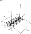
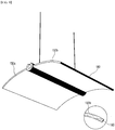
- Fig. 1 is a top perspective view of a lighting device according to an embodiment.
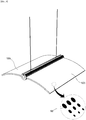
- Fig. 2 is a bottom perspective view of the lighting device shown in Fig. 1 .
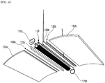
- Fig. 3 is an exploded perspective view of the lighting device shown in Fig. 1 .
- Fig. 4 is an exploded perspective view of the lighting device shown in Fig. 2 .
- Fig. 5 is a cross sectional view of the lighting device shown in Fig. 1 .
- Fig. 6 is a cross sectional view of a body alone shown in Fig. 5 .
- a lighting device 100 may include a body 110, a light source 130a and 130b, a light guide unit 150a and 150b, and an end cap 170a and 170b.
- the body 110 has a predetermined length in one direction and a tubular shape with an empty interior. Also, the body 110 has a consistent or the same cross section in the one direction.
- the light source 130a and 130b is disposed on the outer surface of the body 110.
- the body 110 may include a first surface 111a and a second surface 111b.
- the first light source 130a is disposed on the first surface 111a.
- the second light source 130b is disposed on the second surface 111b.
- the first and the second surfaces 111a and 111b may be disposed symmetrically with each other with respect to the central axis "A" of the body 110.
- the first and the second surfaces 111a and 111b may form a first angle " ⁇ " with the central axis "A".
- the first angle " ⁇ ” is an acute angle and may be from 0 degree to 15 degree.
- the first light source 130a and the second light source 130b disposed on the first surface 111a and the second surface 111b respectively may emit the light through both sides of the body 110 or perpendicularly to the central axis "A".
- the first surface 111a and the second surface 111b may include a flat surface and a curved surface.
- both of the first surface 111a and the second surface 111b may be the flat surface or curved surface.
- the body 110 may include a first receiver 113a and a second receiver 113b.
- the first receiver 113a and the second receiver 113b may be a recess formed toward the inside of the body 110 from the outer surface of the body 110.
- One sides of the first light source 130a and the first light guide unit 150a may be disposed in the first receiver 113a.
- One sides of the second light source 130b and the second light guide unit 150b may be disposed in the second receiver 113b.
- the first receiver 113a and the second receiver 113b may be disposed symmetrically with each other with respect to the central axis "A" of the body 110.
- the bottom surface of the first receiver 113a may be the first surface 111a.
- the bottom surface of the second receiver 113b may be the second surface 111b.
- the first receiver 113a may include a first coupling portion 113a-1. One side of a first fixing plate 120a may be disposed in the first coupling portion 113a-1. The first fixing plate 120a may be coupled to the first coupling portion 113a-1 in a sliding manner.
- the second receiver 113b may also include a second coupling portion 113b-1 which is the same as the first coupling portion 113a-1.
- the body 110 may include a lower portion 116 and an upper portion 118.
- the lower portion 116 and the upper portion 118 may be divided by the first receiver 113a and the second receiver 113b.
- the light guide unit 150a and 150b is disposed between the lower portion 116 and the upper portion 118.
- the lower portion 116 and the upper portion 118 may support the light guide unit 150a and 150b.
- the body 110 may include a connection member 115.
- the connection member 115 may be disposed on the upper portion 118 of the body 110. Specifically, the connection member 115 may be disposed in a groove formed in the upper portion 118 of the body 110. The groove may be formed extending in the longitudinal direction of the body 110.
- the connection member 115 may be integrally formed with the body 110 or may be securely attached to the body 110.
- the connection member 115 may be connected to a rope "L" connected to the ceiling.
- the body 110 may include a catching protrusion 116a and 116b.
- the lower portion 116 of the body 110 may include the first and the second catching protrusions 116a and 116b.
- the first catching protrusion 116a may be formed from the inner surface of the lower portion 116 in parallel with the first surface 111a.
- the first catching protrusion 116a together with the first surface 111a, may form the first coupling portion 113a-1.
- the first catching protrusion 116a, the first surface 111a and the lower portion 116 one side of the first fixing plate 120a may be coupled to the body 110 in a sliding manner. Since the second catching protrusion 116b is the same as the first catching protrusion 116a, detailed descriptions thereof will be omitted.
- the body 110 may be coupled to the first and the second light sources 130a and 130b, the first and the second light guide units 150a and 150b, the first and the second end caps 170a and 170b.
- the first light source 130a and the first light guide unit 150a are coupled to the body 110 in a first direction toward the body 110.
- the second light source 130b and the second light guide unit 150b are coupled to the body 110 in a second direction toward the body 110.
- the first end cap 170a is coupled to the body 110 in a third direction toward the body 110.
- the second end cap 170b is coupled to the body 110 in a fourth direction toward the body 110.
- the third and the fourth directions may be substantially perpendicular to the first and the second directions.
- the body 110 may be made of a metallic material or resin material which has excellent heat radiation efficiency.
- the material of the body 110 is not limited to this.
- the material of the body 110 may include at least one of Al, Ni, Cu, Ag, Sn and Mg.
- the body 110 may include a plurality of heat radiating fins 119.
- the plurality of heat radiating fins 119 may be disposed on at least one of the lower portion 116 and the upper portion 118 of the body 110.
- the plurality of heat radiating fins 119 may be formed in the same direction as the longitudinal direction of the body 110.
- the heat radiating fin 119 increases the surface area of the body 110 and improves the heat radiation effect.
- the fixing plate 120a and 120b is disposed on the body 110. Specifically, the first fixing plate 120a is disposed in the first receiver 113a of the body 110 and on the first surface 111a. The second fixing plate 120b is disposed in the second receiver 113b of the body 110 and on the second surface 111b.
- the first and the second fixing plates 120a and 120b may be coupled to the body 110 in a sliding manner. One sides of the first and the second fixing plates 120a and 120b may be inserted into and coupled to the coupling portion 113a-1 and 113b-1 of the body 110.
- the first light source 130a is disposed on the first fixing plate 120a.
- the second light source 130b is disposed on the second fixing plate 120b.
- the first and the second fixing plates 120a and 120b transfer heat from the first and the second light sources 130a and 130b to the body 110.
- the first and the second fixing plates 120a and 120b may be made of a metallic material.
- the light source 130a and 130b is disposed in the body 110.
- the first light source 130a may be disposed on the first surface 111a of the body 110
- the second light source 130b may be disposed on the second surface 111b of the body 110.
- the first light source 130a may be disposed on the first fixing plate 120a
- the second light source 130b may be disposed on the second fixing plate 120b.
- the first light source 130a may be disposed in the first receiver 113a
- the second light source 130b may be disposed in the second receiver 113b.
- the first and the second light sources 130a and 130b may include substrates 131a and 131b and light emitting devices 133a and 133b respectively.
- the substrates 131a and 131b and the light emitting devices 133a and 133b are disposed on the body 110.
- the substrate 131a and 131b has a rectangular plate shape extending in the longitudinal direction of the body 110.
- the shape of the substrate is not limited to this.
- the substrate 131a and 131b may have a polygonal plate shape.
- two or more substrates 131a of the first light source 130a may be provided.
- at least two substrates may be electrically connected and form the substrates 131a of the first light source 130a.
- the substrate 131b of the second light source 130b may be provided.
- the substrate 131a and 131b may be made by printing a circuit pattern on an insulator.
- the substrate 131a and 131b may include a common printed circuit board (PCB), a metal core PCB, a flexible PCB, a ceramic PCB or the like.
- the substrate 131a and 131b may include a chips on board (COB) allowing an unpackaged LED chip to be directly bonded thereon.
- the substrate 131a and 131b may be a thin sheet made of an insulating material. The sheet may include the circuit pattern.
- the substrate 131a and 131b may be made of a material capable of efficiently reflecting the light. Otherwise, the surface of the substrate 131a and 131b may have a color capable of efficiently reflecting the light, for example, white, silver or the like.
- a plurality of light emitting devices 133a and 133b are disposed on the substrate 131a and 131b.
- the plurality of light emitting devices 133a and 133b may be disposed on the substrate 131a and 131b in one or a plurality of lines.
- the light emitting device 133a and 133b may be a light emitting diode chip which emits red, green or blue light or UV.
- the light emitting diode may have a lateral type or a vertical type and may emit blue, red, yellow or green light.
- the light emitting device 133a and 133b may have phosphor.
- the phosphor may include at least one of garnet based phosphor (YAG, TAG), silicate based phosphor, nitride based phosphor and oxynitride based phosphor.
- the light guide unit 150a and 150b is disposed on the light source 130a and 130b.
- the first light guide unit 150a may be disposed on the first light source 130a
- the second light guide unit 150b may be disposed on the second light source 130b.
- the light guide unit 150a and 150b may have a top surface and a bottom surface, both of which emit the light.
- a plurality of sides of the light guide unit 150a and 150b may be located between the top surface and the bottom surface. At least one of the plurality of sides may be optically coupled to the light source 130a and 130b.
- the first and the second light guide units 150a and 150b may have a quadrangular plate shape respectively. Also, the first and the second light guide units 150a and 150b may have a predetermined curvature respectively and may be curved upward or downward. Here, the shapes of the first and the second light guide units 150a and 150b are not limited to this. The first and the second light guide units 150a and 150b may have a flat plate shape.
- the first and the second light guide units 150a and 150b convert a point light source or a line light source emitted from the first and the second light sources 130a and 130b into a surface light source.
- the one side of the first light guide unit 150a is optically coupled to the first light source 130a.
- the other side of the first light guide unit 150a is located farthest from the body 110.
- the one side of the first light guide unit 150a is disposed on the substrate 131a of the first light source 130a and surrounds the light emitting device 133a.
- the one side of the first light guide unit 150a is disposed in the first receiver 113a of the body 110.
- the one side of the second light guide unit 150b is optically coupled to the second light source 130b.
- the other side of the second light guide unit 150b is located farthest from the body 110.
- the one side of the second light guide unit 150b is disposed on the substrate 131b of the second light source 130b and surrounds the light emitting device 133b.
- the one side of the second light guide unit 150b is disposed in the second receiver 113b of the body 110.
- the body 110 is disposed between the first light guide unit 150a and the second light guide unit 150b. Specifically, the body 110 is disposed between the one side of the first light guide unit 150a and the one side of the second light guide unit 150b. The one side of the first light guide unit 150a and the one side of the second light guide unit 150b are coupled to the body 110. The other side of the first light guide unit 150a and the other side of the second light guide unit 150b are located farthest from the body 110.
- the first light guide unit 150a and the second light guide unit 150b are disposed symmetrically with each other with respect to the central axis "A" of the body 110.
- the first and the second light guide units 150a and 150b may have a shape of which the central portion thereof is upwardly convexly curved. Due to the curved shape, the distribution pattern of the light which is upward emitted from the first and the second light guide units 150a and 150b may become different from the distribution pattern of the light which is downward emitted from the first and the second light guide units 150a and 150b. Specifically, the light emitted from the top surface of the first and the second light guide units 150a and 150b may have a first light distribution pattern in which the light is widely diffused. The light emitted from the bottom surface of the first and the second light guide units 150a and 150b may have a second light distribution pattern in which the light is more narrowly diffused than the light having the first light distribution pattern.
- first and the second light guide units 150a and 150b may have a shape of which the central portion thereof is downwardly convexly curved. Also, the central portion of the first light guide unit 150a may be upwardly convex and the central portion of the second light guide unit 150b may be downwardly convex, and vice versa.
- the thicknesses of the first and the second light guide units 150a and 150b may be, as shown in the drawings, constant. However, the thickness is not limited to this. That is, the thicknesses of the first and the second light guide units 150a and 150b may not be constant. The case where the thicknesses of the first and the second light guide units 150a and 150b are not constant will be described with reference to Figs. 7 to 8 .
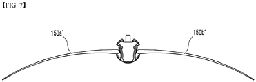
- Fig. 7 is a cross sectional view of a lighting device according to a second embodiment, in other words, a first modified example of the lighting device shown in Fig. 1 .
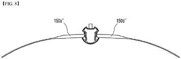
- Fig. 8 is a cross sectional view of a lighting device according to a third embodiment, in other words, a second modified example of the lighting device shown in Fig. 1 .
- the first and the second light guide units 150a' and 150b' of the lighting device according to the second embodiment become thinner from one side to the other side thereof.
- the emission rate of the light which totally reflects and traverses within the first and the second light guide units 150a' and 150b' can be more increased than the emission ratio of the lighting device according to the first embodiment is.
- the first and the second light guide units 150a" and 150b" of the lighting device according to the third embodiment become thinner from one side to the other side thereof.
- the first and the second light guide units 150a" and 150b" are different from the first and the second light guide units 150a' and 150b' according to the second embodiment.
- the thicknesses of the first and the second light guide units 150a' and 150b' of the lighting device according to the second embodiment are reduced gradually or at a predetermined reduction rate (a first reduction rate) from one side to the other side thereof
- the thicknesses of the first and the second light guide units 150a" and 150b" of the lighting device according to the third embodiment are reduced at a predetermined reduction rate (a second reduction rate) in a portion between one side and the other side thereof and are constant in the other portions respectively.
- the second reduction rate is higher than the first reduction rate.
- the emission rate of the light of the lighting device according to the third embodiment can be more increased than the emission ratio of the lighting device according to the first embodiment is.
- the first and the second light guide units 150a and 150b may further include a reflector. This will be specifically described with reference to Fig. 9 .
- Fig. 9 is a cross sectional view of a lighting device according to a fourth embodiment, in other words, a third modified example of the lighting device shown in Fig. 1 .
- the lighting device according to the fourth embodiment is obtained by adding a reflector 180 to the lighting device shown in Figs. 1 to 6 .
- the reflector 180 can be applied to the lighting device shown in the second to the third embodiments and the below-described lighting device according to another embodiment.
- the reflector 180 may be disposed on the surfaces of the first and/or the second light guide unit 150a and 150b. More specifically, the reflector 180 may be disposed on one of several sides of the first and/or the second light guide unit 150a and 150b, for example, a side located farthest from the first and/or the second light source 130a and 130b. Due to the reflector 180, the light which is emitted through the one sides of the first and the second light guide unit 150a and 150b may be incident again on the sides. Therefore, the light which is expected to be emitted to the outside through the one sides of the first and/or the second light guide unit 150a and 150b and lost can be reused. That is, the reflector 180 enables the lighting device according to the fourth embodiment to more improve light extraction efficiency than the lighting device according to the first embodiment.
- the reflector 180 may be disposed not only on the one side of the first and/or the second light guide unit 150a and 150b but also on at least one of the top, bottom and other sides of the first and/or the second light guide unit 150a and 150b.
- the lighting device according to the fourth embodiment may emit the light in either only the up direction or only the down direction.
- the reflector 180 may be a reflective sheet capable of reflecting light or may be coated or deposited on one side of the first and the second light guide units 150a and 150b.
- the first and the second light guide units 150a and 150b may further include an optical part. This will be specifically described with reference to Fig. 10 .
- Fig. 10 is a cross sectional view of a lighting device according to a fifth embodiment, in other words, a fourth modified example of the lighting device shown in Fig. 1 .
- the lighting device according to the fifth embodiment may be obtained by further including an optical part 195 to the lighting device 100 shown in Figs. 1 to 6 .
- the optical part 195 can be applied to the lighting device shown in the second to the fourth embodiments and the below-described lighting device according to another embodiment.
- the optical part 195 may be disposed on one side of the first and/or the second light guide unit 150a and 150b. Specifically, the optical part 195 may be disposed on at least one of the top and the bottom surfaces of the first and/or the second light guide unit 150a and 150b.
- the optical part 195 may be a print pattern or prism (fine optic).
- the optical part 195 is able to control the distribution pattern of light which is emitted through the top surface and the bottom surface of the first and/or the second light guide units 150a and 150b or to control the distribution ratio between the light which is emitted through the top surface and the light which is emitted through the bottom surface of the first and/or the second light guide units 150a and 150b.
- more optical parts 195 are disposed on the top surface than on the bottom surface of the first and/or the second light guide unit 150a and 150b, so that it is possible to control the distribution ratio between the light which is emitted through the top surface and the light which is emitted through the bottom surface of the first and/or the second light guide units 150a and 150b. Also, it is possible to control the light distribution pattern by differentiating the print patterns of the top and the bottom surfaces of the first and/or the second light guide unit 150a and 150b.
- the optical part 195 may be comprised of a plurality of dot patterns.
- the sizes of the plurality of dot patterns may be different from each other. For example, the sizes of the dot patterns may become smaller from one side to the other side of the first and/or the second light guide unit 150a and 150b.
- the end cap 170a and 170b is disposed on the body 110. Specifically, the first end cap 170a is coupled to one of both ends of the body 110, and the second end cap 170b is coupled to the other of both ends of the body 110.
- the first and the second end caps 170a and 170b may cover both of the upper portion 118 and the lower portion 116 of the body 110.
- the first and the second end caps 170a and 170b are coupled to the body 110, so that it is possible to prevent the first and the second fixing plates 120a and 120b from being separated from the body 110 and to prevent the introduction of insects or impurities into the inside of the body 110 by blocking the both ends of the body 110.
- the first and the second end caps 170a and 170b are made of the same material as that of the body 110, thereby improving the heat radiation performance of the lighting device 100.
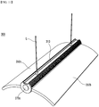
- Fig. 11 is a perspective view of a lighting device according to a sixth embodiment.
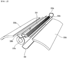
- Fig. 12 is an exploded perspective view of the lighting device shown in Fig. 11 .
- Fig. 13 is a bottom perspective view of the lighting device shown in Fig. 12 .
- Fig. 14 is a cross sectional view of the lighting device shown in Fig. 11 .
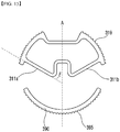
- Fig. 15 is a cross sectional view showing a body and cover alone shown in Fig. 14 .
- a lighting device 300 may include a body 310, a light source 330a and 330b, a light guide unit 350a and 350b, an end cap 370a and 370b, and a cover 390.
- the configuration of the lighting device 300 according to the sixth embodiment is similar to that of the lighting device 100 according to the first embodiment.
- configuration or part different from that of the lighting device 100 according to the first embodiment will be specifically described, and the configuration or part the same as or similar to that of the lighting device 100 according to the first embodiment will be replaced by the description of the lighting device 100 according to the first embodiment.
- the body 310 may include a first surface 311a on which a first light source 330a is disposed, and a second surface 311b on which a second light source 330b is disposed.
- the first and the second surfaces 311a and 311b are disposed symmetrically with each other with respect to the central axis "A".
- the first and the second surfaces 311a and 311b may form a second angle " ⁇ " with the central axis "A".
- the second angle " ⁇ " is an acute angle and may be from 50 degree to 90 degree. Therefore, as the second angle " ⁇ " is closer to 90 degree, the light is emitted from the first light source 330a and the second light source 330b disposed on the first surface 311a and the second surface 311b respectively in the down direction of the body 110 or in a direction of the central axis "A".
- the light guide unit 350a and 350b is disposed on the light source 330a and 330b. Specifically, the first light guide unit 350a may be disposed on the first light source 330a, and the second light guide unit 350b may be disposed on the second light source 330b.
- One side of the first light guide unit 350a is optically coupled to a light emitting device 333a of the first light source 330a and is disposed on a substrate 331a.
- the one side of the first light guide unit 350a may have a curved portion 351a.
- the curved portion 351a may be a portion of the bottom surface of the first light guide unit 350a.
- the curved portion 351a totally reflects all of the light emitted from the light emitting device 333a. In this case, since the light cannot be emitted to the outside through the curved portion 351a, more amount of light emitted from the light emitting device 333a can be transmitted to the other side of the first light guide unit 350a without being emitted through the curved portion 351a to the outside.
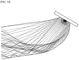
- Fig. 16 shows a simulation result obtained by tracing optical paths of the curved portion.
- the curvature of the curved portion 351a may be designed in such a manner as to have a specific value capable of totally reflecting all of the light emitted from the light emitting device 333a.
- the cover 390 may be disposed under and spaced apart from the body 310 at a predetermined distance.
- the first and the second light guide units 350a and 350b are placed between the cover 390 and the body 310, and the cover 390 and the body 310 may be coupled to each other by the first and the second end caps 370a and 370b.
- the material of the cover 390 may be the same as or not the same as that of the body 310.
- the cover 390 may have a heat radiating fin 395 like a heat radiating fin 319 of the body 310.
- the cover 390 is coupled to the body 310 and supports the first and the second light guide units 350a and 350b.
- the cover 390 is made of an opaque or translucent material, thereby blocking the one sides of the first and the second light sources 330a and 330b and the first and the second light guide units 350a and 350b such that the one sides cannot be seen.
- Fig. 17 is a perspective view of a lighting device according to a seventh embodiment.
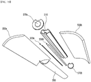
- Fig. 18 is an exploded perspective view of the lighting device shown in Fig. 17 .
- Fig. 19 is a bottom perspective view of the lighting device shown in Fig. 17 .
- Fig. 20 is a cross sectional view of the lighting device shown in Fig. 17 .
- a lighting device 500 may include a body 510, a light source 530a and 530b, a light guide unit 550a and 550b, an end cap 570a and 570b, and a cover 590.
- the configuration of the lighting device 500 according to the seventh embodiment is similar to that of the lighting device 300 according to the sixth embodiment.
- configuration or part different from that of the lighting device 300 according to the sixth embodiment will be specifically described, and the configuration or part the same as or similar to that of the lighting device 300 according to the sixth embodiment will be replaced by the description of the lighting device 300 according to the sixth embodiment.
- the light guide unit 550a and 550b is disposed on the light source 530a and 530b. Specifically, the first light guide unit 550a may be disposed on the first light source 530a, and the second light guide unit 550b may be disposed on the second light source 530b.
- One side of the first light guide unit 550a is optically coupled to a light emitting device 533a of the first light source 330a and is disposed on a substrate 531a.
- the one side of the first light guide unit 550a may have a curved portion 551a.
- the curved portion 551a may be a portion of the bottom surface of the first light guide unit 550a.
- the curved portion 551a reflects a part of the light emitted from the light emitting device 533a and allows the rest of the light to pass therethrough. Therefore, a predetermined amount of the light is emitted from the curved portion 551a, and the emitted light travels toward the cover 590.
- the inner surface of the cover 590 receives the light which is emitted from the curved portion 551a of the first and the second light guide units 550a and 550b, and the outer surface of the cover 590 emits the light incident on the inner surface of the cover 590.
- the cover 590 may be made of a transparent or translucent glass or plastic resin material.
- the cover 590 may diffuse the light from the first and the second light guide units 550a and 550b and emit. When the cover 590 also emits the light, an optical uniformity of the light emitted from the entire lighting device 500 can be improved.
- the lighting device 500 according to the seventh embodiment is different from the lighting device 300 according to the sixth embodiment in that the cover 590 emits the light.
- the curved portion 551a of the first and the second light guide units 550a and 550b of the lighting device 500 according to the seventh embodiment allows a part of the light from the light emitting device 533a to pass therethrough.
- the curved portion 551a may have a predetermined condition. Specifically, the condition will be described in detail with reference to Fig. 21 .
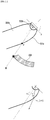
- Fig. 21 is a conceptual view for describing the condition of curved portions of a first light guide unit and a second light guide unit.
- a critical angle "y" of the curved portion 551a should have a predetermined condition so as to allow a part of the light from the light emitting device 533a to pass the curved portion 551a.
- the predetermined condition is that the critical angle "y" of the curved portion 551a is greater than an incident angle "x" of the light incident on the curved portion 551a.
- the critical angle "y” of the curved portion 551a is determined by sin -1 (n2/n1).
- n1 is a refractive index of the first light guide unit 550a
- n2 is a refractive index of the air.
- the incident angle "x" corresponds to an angle between any light emitted from the light emitting device 533a and a normal at a point where the curved portion 551a meets the any light.
- the curved portion 551a may be determined by the light emitting device 533a and the cover 590.
- the range of the curved portion 551a is a portion of the bottom surface of the first light guide unit 550a.
- the portion may have a range from one side of the first light guide unit 550a to a point "P".
- the point "P" is an intersection between the first light guide unit 550a and a segment “M” connecting the center of the light emitting device 533a with one end point of the cover 590.
- the curved portion 551a is determined within a predetermined range of the first light guide unit 550a.
- the curved portion 551a having a condition in which the critical angle "y" is greater than the incident angle "x" within the predetermined range may allow a part of the light from the light emitting device 533a to pass therethrough.
- the incident angle "x" of the light incident on the curved portion 551a is greater than the critical angle "y" of the curved portion 551a, all light incident from the light emitting device 533a is totally reflected.
- This may be a condition of one side of the light guide unit 130a and 130b of the lighting device 100 according to the first embodiment and a condition of the curved portion 351a of the lighting device 300 according to the sixth embodiment.
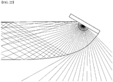
- Fig. 22 is a simulation result obtained by tracing optical paths of the curved portion shown in Fig. 20 .
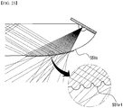
- the curved portion 551a may have a prism structure in order to allow a part of the light from the light emitting device 533a to pass therethrough. This will be described with reference to Fig. 23 .
- Fig. 23 is a partial cross sectional view of a lighting device according to an eighth embodiment, in other words, a first modified example of the lighting device shown in Fig. 17 .
- a prism structure 551a-1 is added to the curved portion 551a, so that the curved portion 551a can allow a part of the light emitted from the light emitting device to pass therethrough without reflection.
- Such a prism structure 551a-1 may be used for the curved portion 551a to totally reflect the light from the light emitting device.
- the prism structure 551a-1 may have an uneven structure which is formed to protrude outwardly from the surface of the curved portion 551a.
- the curved portion 351a of the lighting device 300 according to the sixth embodiment may allow a part of the light from the light emitting device 333a to pass therethrough without total reflection.
- Figs. 24 to 25 are perspective views showing modified examples of a cover shown in Fig. 17 .
- a cover 590' and 590" may be made of an opaque material instead of a transparent or translucent material and may include an optical transmitting plate 595' and 595". The light may be emitted from the cover 590' and 590" through the optical transmitting plate 595' and 595".
- the optical transmitting plate 595' and 595" may have, as shown in Fig. 24 , a circular shape or may have, as shown in Fig. 25 , a quadrangular shape. Further, the optical transmitting plate 595' and 595" may have various shapes such as an elliptical shape, a polygonal shape or the like.
Landscapes
- Physics & Mathematics (AREA)
- Engineering & Computer Science (AREA)
- General Engineering & Computer Science (AREA)
- General Physics & Mathematics (AREA)
- Optics & Photonics (AREA)
- Planar Illumination Modules (AREA)
- Non-Portable Lighting Devices Or Systems Thereof (AREA)
- Led Device Packages (AREA)
- Light Guides In General And Applications Therefor (AREA)
- Optical Couplings Of Light Guides (AREA)
- Fastening Of Light Sources Or Lamp Holders (AREA)
- Arrangement Of Elements, Cooling, Sealing, Or The Like Of Lighting Devices (AREA)
Description
- Embodiments may relate to a lighting device.
- A light emitting diode (LED) is a semiconductor element for converting electric energy into light. The LED has advantages of low power consumption, a semi-permanent span of life, a rapid response speed, safety and an environment-friendliness. Therefore, many researches are devoted to substitution of the existing light sources with the LED. The LED is now being increasingly used as a light source for lighting devices, for example, various lamps used interiorly and exteriorly, a liquid crystal display device, an electric sign and a street lamp and the like.
-
US 2008/0219001 A1 discloses an LED light fixture comprising an LED array producing light and a light diffuser for diffusing the light from the LED array. - The embodiment of the present invention provides a new structured lighting device using a light guide unit.
- Also, the embodiment of the present invention provides a lighting device capable of controlling an up/down light distribution ratio.
- Also, the embodiment of the present invention provides a lighting device capable of controlling an up/down light distribution pattern.
- The invention is defined by the subject-matter of
claim 1. Embodiments not covered byclaim 1 do not form part of the invention but represent background information which is useful for understanding the invention. One embodiment includes: a body; a first light source and a second light source, which are disposed on the body and are disposed symmetrically with each other with respect to a central axis of the body; a first light guide unit which is disposed on the first light source and is coupled to the body; and a second light guide unit which is disposed on the second light source and is coupled to the body. The first light guide unit and the second light guide unit are disposed symmetrically with each other with respect to the central axis of the body. - The body may include a first receiver receiving the first light source, and a second receiver receiving the second light source. The first receiver may receive one side of the first light guide unit, and the second receiver receives one side of the second light guide unit.
- The lighting device may further include a first fixing plate which is disposed in the first receiver and disposed between the first light source and the body, and a second fixing plate which is disposed in the second receiver and disposed between the second light source and the body.
- The body may include a coupling portion which is coupled to one sides of the first and the second fixing plates.
- The first and the second fixing plates may be coupled to the coupling portion in a sliding manner.
- The body may include a first surface on which the first light source is disposed, and a second surface on which the second light source is disposed. The first and the second surfaces may form an acute angle with the central axis of the body.
- Each of the first and the second light guide units may include a top surface, a bottom surface and a plurality of sides. The first light source may emit light toward one of the plurality of sides of the first light guide unit.
- Each of the first and the second light guide units may have a shape curved upward or downward.
- The thickness of each of the first and the second light guide units may be reduced from one side to the other side thereof.
- The first light guide unit may include a portion disposed between one side and the other side thereof. The thickness of the portion may be reduced from one side to the other side of the first light guide unit.
- The lighting device may further include an optical part which is disposed on at least one of the top surface and the bottom surface of the first light guide unit and controls a distribution pattern of light which is emitted through the top surface and the bottom surface of the first light guide unit or controls a distribution ratio between the light which is emitted through the top surface and the light which is emitted through the bottom surface of the first light guide unit.
- The optical part may have a print pattern or a prism structure.
- The lighting device may further include a reflector disposed on at least one of the top surface, the bottom surface and the plurality of sides of the first light guide unit.
- The reflector is disposed on one side of the first light guide unit.
- The lighting device may further include a first end cap and a second end cap which are coupled to both ends of the body respectively.
- The body may include a connection member which is connected to a rope connected to the outside.
- Another embodiment is a lighting device that includes: a body; a first light source and a second light source, which are disposed on the body, are disposed symmetrically with each other with respect to a central axis of the body and include at least one light emitting device; a first light guide unit which has one side optically coupled to the first light source; and a second light guide unit which has one side optically coupled to the second source. The body includes a first surface on which the first light source is disposed, and a second surface on which the second light source is disposed. The first and the second surfaces form an acute angle with the central axis of the body.
- The one side of the first light guide unit may include at least one curved portion on which light from the light emitting device is incident.
- The curved portion may totally reflect all of the light emitted from the light emitting device.
- The curved portion may include a prism structure for allowing a part of the light from the light emitting device to pass therethrough.
- The curved portion may allow a part of the light from the light emitting device to pass therethrough.
- The lighting device may further include a cover which is disposed under the one sides of the first and the second light guide units and allows the light from the curved portion to pass therethrough.
- The cover may be made of an opaque material and may include an optical transmitting plate for allowing the light from the curved portion to pass therethrough.
- Further another embodiment is a lighting device that includes: a body which has a side; a light source which includes a substrate disposed on the side of the body and a light emitting device disposed on a side of the substrate; and a light guide unit which is disposed on the light source and includes a side having a surface on which light from the light emitting device is incident. The side of the light guide unit further includes a curved portion on which the light has passed through the surface is incident. A critical angle of the curved portion is greater than an incident angle of the light incident on the curved portion.
- The lighting device may include a cover disposed under the side of the light guide unit. The curved portion may have a range from the side of the light guide unit to a first point. The first point may be an intersection between the light guide unit and a segment connecting the light emitting device with one end of the cover.
- According to the embodiment, a new structured lighting device using the light guide unit can be implemented.
- Also, according to the embodiment, it is possible to control an up/down light distribution ratio.
- Also, according to the embodiment, it is possible to control an up/down light distribution pattern.
-
-
Fig. 1 is a top perspective view of a lighting device according to an embodiment; -
Fig. 2 is a bottom perspective view of the lighting device shown inFig. 1 ; -
Fig. 3 is an exploded perspective view of the lighting device shown inFig. 1 ; -
Fig. 4 is an exploded perspective view of the lighting device shown inFig. 2 ; -
Fig. 5 is a cross sectional view of the lighting device shown inFig. 1 ; -
Fig. 6 is a cross sectional view of a body alone shown inFig. 5 ; -
Fig. 7 is a cross sectional view of a lighting device according to a second embodiment, in other words, a first modified example of the lighting device shown inFig. 1 ; -
Fig. 8 is a cross sectional view of a lighting device according to a third embodiment, in other words, a second modified example of the lighting device shown inFig. 1 ; -
Fig. 9 is a cross sectional view of a lighting device according to a fourth embodiment, in other words, a third modified example of the lighting device shown inFig. 1 ; -
Fig. 10 is a cross sectional view of a lighting device according to a fifth embodiment, in other words, a fourth modified example of the lighting device shown inFig. 1 ; -
Fig. 11 is a perspective view of a lighting device according to a sixth embodiment; -
Fig. 12 is an exploded perspective view of the lighting device shown inFig. 11 ; -
Fig. 13 is a bottom perspective view of the lighting device shown inFig. 12 ; -
Fig. 14 is a cross sectional view of the lighting device shown inFig. 11 ; -
Fig. 15 is a cross sectional view showing a body and cover alone shown inFig. 14 ; -
Fig. 16 is a simulation result obtained by tracing optical paths of a curved portion shown inFig. 14 ; -
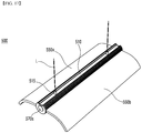
Fig. 17 is a perspective view of a lighting device according to a seventh embodiment; -
Fig. 18 is an exploded perspective view of the lighting device shown inFig. 17 ; -
Fig. 19 is a bottom perspective view of the lighting device shown inFig. 17 ; -
Fig. 20 is a cross sectional view of the lighting device shown inFig. 17 ; -
Fig. 21 is a conceptual view for describing the condition of curved portions of a first light guide unit and a second light guide unit; -
Fig. 22 is a simulation result obtained by tracing optical paths of a curved portion shown inFig. 20 ; -
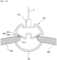
Fig. 23 is a partial cross sectional view of a lighting device according to an eighth embodiment, in other words, a first modified example of the lighting device shown inFig. 17 ; and -
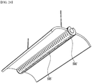
Figs. 24 to 25 are perspective views showing modified examples of a cover shown inFig. 17 . - Hereafter, an embodiment of the present invention will be described in detail with reference to accompanying drawings. However, the accompanied drawings are provided only for more easily describing the present invention. It is easily understood by those skilled in the art that the scope of the present invention is not limited to the scope of the accompanied drawings.
- A criterion for "on" and "under" of each layer will be described based on the drawings. A thickness or a size of each layer may be magnified, omitted or schematically shown for the purpose of convenience and clearness of description. The size of each component may not necessarily mean its actual size.
- In description of embodiments of the present invention, when it is mentioned that an element is formed "on" or "under" another element, it means that the mention includes a case where two elements are formed directly contacting with each other or are formed such that at least one separate element is interposed (indirectly) between the two elements. The "on" and "under" will be described to include the upward and downward directions based on one element.
-
Fig. 1 is a top perspective view of a lighting device according to an embodiment.Fig. 2 is a bottom perspective view of the lighting device shown inFig. 1 .Fig. 3 is an exploded perspective view of the lighting device shown inFig. 1 .Fig. 4 is an exploded perspective view of the lighting device shown inFig. 2 .Fig. 5 is a cross sectional view of the lighting device shown inFig. 1 .Fig. 6 is a cross sectional view of a body alone shown inFig. 5 . - Referring to
Figs. 1 to 6 , alighting device 100 according to the first embodiment may include abody 110, alight source light guide unit end cap - The
body 110 has a predetermined length in one direction and a tubular shape with an empty interior. Also, thebody 110 has a consistent or the same cross section in the one direction. - The
light source body 110. Specifically, thebody 110 may include afirst surface 111a and asecond surface 111b. Thefirst light source 130a is disposed on thefirst surface 111a. The secondlight source 130b is disposed on thesecond surface 111b. - The first and the
second surfaces body 110. The first and thesecond surfaces first light source 130a and the secondlight source 130b disposed on thefirst surface 111a and thesecond surface 111b respectively may emit the light through both sides of thebody 110 or perpendicularly to the central axis "A". - The
first surface 111a and thesecond surface 111b may include a flat surface and a curved surface. Here, both of thefirst surface 111a and thesecond surface 111b may be the flat surface or curved surface. - The
body 110 may include afirst receiver 113a and asecond receiver 113b. Thefirst receiver 113a and thesecond receiver 113b may be a recess formed toward the inside of thebody 110 from the outer surface of thebody 110. One sides of thefirst light source 130a and the firstlight guide unit 150a may be disposed in thefirst receiver 113a. One sides of the secondlight source 130b and the secondlight guide unit 150b may be disposed in thesecond receiver 113b. - The
first receiver 113a and thesecond receiver 113b may be disposed symmetrically with each other with respect to the central axis "A" of thebody 110. The bottom surface of thefirst receiver 113a may be thefirst surface 111a. The bottom surface of thesecond receiver 113b may be thesecond surface 111b. - The
first receiver 113a may include afirst coupling portion 113a-1. One side of afirst fixing plate 120a may be disposed in thefirst coupling portion 113a-1. Thefirst fixing plate 120a may be coupled to thefirst coupling portion 113a-1 in a sliding manner. Thesecond receiver 113b may also include asecond coupling portion 113b-1 which is the same as thefirst coupling portion 113a-1. - The
body 110 may include alower portion 116 and anupper portion 118. Here, thelower portion 116 and theupper portion 118 may be divided by thefirst receiver 113a and thesecond receiver 113b. Thelight guide unit lower portion 116 and theupper portion 118. Here, thelower portion 116 and theupper portion 118 may support thelight guide unit - The
body 110 may include aconnection member 115. Theconnection member 115 may be disposed on theupper portion 118 of thebody 110. Specifically, theconnection member 115 may be disposed in a groove formed in theupper portion 118 of thebody 110. The groove may be formed extending in the longitudinal direction of thebody 110. Theconnection member 115 may be integrally formed with thebody 110 or may be securely attached to thebody 110. Theconnection member 115 may be connected to a rope "L" connected to the ceiling. - The
body 110 may include a catchingprotrusion lower portion 116 of thebody 110 may include the first and the second catchingprotrusions first catching protrusion 116a may be formed from the inner surface of thelower portion 116 in parallel with thefirst surface 111a. Thefirst catching protrusion 116a, together with thefirst surface 111a, may form thefirst coupling portion 113a-1. By the first catchingprotrusion 116a, thefirst surface 111a and thelower portion 116, one side of thefirst fixing plate 120a may be coupled to thebody 110 in a sliding manner. Since the second catchingprotrusion 116b is the same as the first catchingprotrusion 116a, detailed descriptions thereof will be omitted. - The
body 110 may be coupled to the first and thesecond light sources light guide units second end caps first light source 130a and the firstlight guide unit 150a are coupled to thebody 110 in a first direction toward thebody 110. The secondlight source 130b and the secondlight guide unit 150b are coupled to thebody 110 in a second direction toward thebody 110. Thefirst end cap 170a is coupled to thebody 110 in a third direction toward thebody 110. Thesecond end cap 170b is coupled to thebody 110 in a fourth direction toward thebody 110. The third and the fourth directions may be substantially perpendicular to the first and the second directions. - The
body 110 may be made of a metallic material or resin material which has excellent heat radiation efficiency. However, the material of thebody 110 is not limited to this. For example, the material of thebody 110 may include at least one of Al, Ni, Cu, Ag, Sn and Mg. - The
body 110 may include a plurality ofheat radiating fins 119. Specifically, the plurality ofheat radiating fins 119 may be disposed on at least one of thelower portion 116 and theupper portion 118 of thebody 110. The plurality ofheat radiating fins 119 may be formed in the same direction as the longitudinal direction of thebody 110. Theheat radiating fin 119 increases the surface area of thebody 110 and improves the heat radiation effect. - The fixing
plate body 110. Specifically, thefirst fixing plate 120a is disposed in thefirst receiver 113a of thebody 110 and on thefirst surface 111a. Thesecond fixing plate 120b is disposed in thesecond receiver 113b of thebody 110 and on thesecond surface 111b. - The first and the
second fixing plates body 110 in a sliding manner. One sides of the first and thesecond fixing plates coupling portion 113a-1 and 113b-1 of thebody 110. - The
first light source 130a is disposed on thefirst fixing plate 120a. The secondlight source 130b is disposed on thesecond fixing plate 120b. The first and thesecond fixing plates second light sources body 110. For this, like thebody 110, the first and thesecond fixing plates - The
light source body 110. Specifically, thefirst light source 130a may be disposed on thefirst surface 111a of thebody 110, and the secondlight source 130b may be disposed on thesecond surface 111b of thebody 110. Also, thefirst light source 130a may be disposed on thefirst fixing plate 120a, and the secondlight source 130b may be disposed on thesecond fixing plate 120b. Also, thefirst light source 130a may be disposed in thefirst receiver 113a, and the secondlight source 130b may be disposed in thesecond receiver 113b. - The first and the
second light sources substrates devices substrates light emitting devices body 110. - The
substrate body 110. However, the shape of the substrate is not limited to this. For example, thesubstrate more substrates 131a of thefirst light source 130a may be provided. Specifically, at least two substrates may be electrically connected and form thesubstrates 131a of thefirst light source 130a. The same is true for thesubstrate 131b of the secondlight source 130b. - The
substrate substrate substrate substrate - The
substrate substrate - A plurality of light emitting
devices substrate devices substrate - The
light emitting device - The
light emitting device light emitting device - The
light guide unit light source light guide unit 150a may be disposed on thefirst light source 130a, and the secondlight guide unit 150b may be disposed on the secondlight source 130b. More specifically, thelight guide unit light guide unit light source - The first and the second
light guide units light guide units light guide units light guide units - The first and the second
light guide units second light sources - The one side of the first
light guide unit 150a is optically coupled to thefirst light source 130a. The other side of the firstlight guide unit 150a is located farthest from thebody 110. The one side of the firstlight guide unit 150a is disposed on thesubstrate 131a of thefirst light source 130a and surrounds thelight emitting device 133a. The one side of the firstlight guide unit 150a is disposed in thefirst receiver 113a of thebody 110. - The one side of the second
light guide unit 150b is optically coupled to the secondlight source 130b. The other side of the secondlight guide unit 150b is located farthest from thebody 110. The one side of the secondlight guide unit 150b is disposed on thesubstrate 131b of the secondlight source 130b and surrounds thelight emitting device 133b. The one side of the secondlight guide unit 150b is disposed in thesecond receiver 113b of thebody 110. - The
body 110 is disposed between the firstlight guide unit 150a and the secondlight guide unit 150b. Specifically, thebody 110 is disposed between the one side of the firstlight guide unit 150a and the one side of the secondlight guide unit 150b. The one side of the firstlight guide unit 150a and the one side of the secondlight guide unit 150b are coupled to thebody 110. The other side of the firstlight guide unit 150a and the other side of the secondlight guide unit 150b are located farthest from thebody 110. - The first
light guide unit 150a and the secondlight guide unit 150b are disposed symmetrically with each other with respect to the central axis "A" of thebody 110. - The first and the second
light guide units light guide units light guide units light guide units light guide units light guide units light guide unit 150a may be upwardly convex and the central portion of the secondlight guide unit 150b may be downwardly convex, and vice versa. - The thicknesses of the first and the second
light guide units light guide units light guide units Figs. 7 to 8 . -
Fig. 7 is a cross sectional view of a lighting device according to a second embodiment, in other words, a first modified example of the lighting device shown inFig. 1 .Fig. 8 is a cross sectional view of a lighting device according to a third embodiment, in other words, a second modified example of the lighting device shown inFig. 1 . - Referring to
Fig. 7 , the first and the secondlight guide units 150a' and 150b' of the lighting device according to the second embodiment become thinner from one side to the other side thereof. In this case, the emission rate of the light which totally reflects and traverses within the first and the secondlight guide units 150a' and 150b' can be more increased than the emission ratio of the lighting device according to the first embodiment is. - Referring to
Fig. 8 , the first and the secondlight guide units 150a" and 150b" of the lighting device according to the third embodiment become thinner from one side to the other side thereof. However, the first and the secondlight guide units 150a" and 150b" are different from the first and the secondlight guide units 150a' and 150b' according to the second embodiment. That is, while the thicknesses of the first and the secondlight guide units 150a' and 150b' of the lighting device according to the second embodiment are reduced gradually or at a predetermined reduction rate (a first reduction rate) from one side to the other side thereof, the thicknesses of the first and the secondlight guide units 150a" and 150b" of the lighting device according to the third embodiment are reduced at a predetermined reduction rate (a second reduction rate) in a portion between one side and the other side thereof and are constant in the other portions respectively. Here, the second reduction rate is higher than the first reduction rate. Like the lighting device according to the second embodiment, the emission rate of the light of the lighting device according to the third embodiment can be more increased than the emission ratio of the lighting device according to the first embodiment is. - Referring back to
Figs. 1 to 6 , the first and the secondlight guide units Fig. 9 . -
Fig. 9 is a cross sectional view of a lighting device according to a fourth embodiment, in other words, a third modified example of the lighting device shown inFig. 1 . - Referring to
Fig. 9 , the lighting device according to the fourth embodiment is obtained by adding areflector 180 to the lighting device shown inFigs. 1 to 6 . Here, thereflector 180 can be applied to the lighting device shown in the second to the third embodiments and the below-described lighting device according to another embodiment. - The
reflector 180 may be disposed on the surfaces of the first and/or the secondlight guide unit reflector 180 may be disposed on one of several sides of the first and/or the secondlight guide unit light source reflector 180, the light which is emitted through the one sides of the first and the secondlight guide unit light guide unit reflector 180 enables the lighting device according to the fourth embodiment to more improve light extraction efficiency than the lighting device according to the first embodiment. - The
reflector 180 may be disposed not only on the one side of the first and/or the secondlight guide unit light guide unit reflector 180 is disposed on one of the top and the bottom surfaces of the first and/or the secondlight guide unit - The
reflector 180 may be a reflective sheet capable of reflecting light or may be coated or deposited on one side of the first and the secondlight guide units - Referring back to
Figs. 1 to 6 , the first and the secondlight guide units Fig. 10 . -
Fig. 10 is a cross sectional view of a lighting device according to a fifth embodiment, in other words, a fourth modified example of the lighting device shown inFig. 1 . - Referring to
Fig. 10 , the lighting device according to the fifth embodiment may be obtained by further including anoptical part 195 to thelighting device 100 shown inFigs. 1 to 6 . Here, theoptical part 195 can be applied to the lighting device shown in the second to the fourth embodiments and the below-described lighting device according to another embodiment. - The
optical part 195 may be disposed on one side of the first and/or the secondlight guide unit optical part 195 may be disposed on at least one of the top and the bottom surfaces of the first and/or the secondlight guide unit - The
optical part 195 may be a print pattern or prism (fine optic). Theoptical part 195 is able to control the distribution pattern of light which is emitted through the top surface and the bottom surface of the first and/or the secondlight guide units light guide units optical parts 195 are disposed on the top surface than on the bottom surface of the first and/or the secondlight guide unit light guide units light guide unit - The
optical part 195 may be comprised of a plurality of dot patterns. The sizes of the plurality of dot patterns may be different from each other. For example, the sizes of the dot patterns may become smaller from one side to the other side of the first and/or the secondlight guide unit - Referring back to
Figs. 1 to 6 , theend cap body 110. Specifically, thefirst end cap 170a is coupled to one of both ends of thebody 110, and thesecond end cap 170b is coupled to the other of both ends of thebody 110. The first and thesecond end caps upper portion 118 and thelower portion 116 of thebody 110. - The first and the
second end caps body 110, so that it is possible to prevent the first and thesecond fixing plates body 110 and to prevent the introduction of insects or impurities into the inside of thebody 110 by blocking the both ends of thebody 110. - The first and the
second end caps body 110, thereby improving the heat radiation performance of thelighting device 100. -
Fig. 11 is a perspective view of a lighting device according to a sixth embodiment.Fig. 12 is an exploded perspective view of the lighting device shown inFig. 11 .Fig. 13 is a bottom perspective view of the lighting device shown inFig. 12 .Fig. 14 is a cross sectional view of the lighting device shown inFig. 11 .Fig. 15 is a cross sectional view showing a body and cover alone shown inFig. 14 . - Referring to
Figs. 11 to 15 , alighting device 300 according to the sixth embodiment may include abody 310, alight source light guide unit end cap cover 390. - The configuration of the
lighting device 300 according to the sixth embodiment is similar to that of thelighting device 100 according to the first embodiment. In the following description of thelighting device 300 according to the sixth embodiment, configuration or part different from that of thelighting device 100 according to the first embodiment will be specifically described, and the configuration or part the same as or similar to that of thelighting device 100 according to the first embodiment will be replaced by the description of thelighting device 100 according to the first embodiment. - The
body 310 may include afirst surface 311a on which afirst light source 330a is disposed, and asecond surface 311b on which a secondlight source 330b is disposed. The first and thesecond surfaces - The first and the
second surfaces first light source 330a and the secondlight source 330b disposed on thefirst surface 311a and thesecond surface 311b respectively in the down direction of thebody 110 or in a direction of the central axis "A". - The
light guide unit light source light guide unit 350a may be disposed on thefirst light source 330a, and the secondlight guide unit 350b may be disposed on the secondlight source 330b. - One side of the first
light guide unit 350a is optically coupled to alight emitting device 333a of thefirst light source 330a and is disposed on asubstrate 331a. - The one side of the first
light guide unit 350a may have acurved portion 351a. Here, thecurved portion 351a may be a portion of the bottom surface of the firstlight guide unit 350a. Thecurved portion 351a totally reflects all of the light emitted from thelight emitting device 333a. In this case, since the light cannot be emitted to the outside through thecurved portion 351a, more amount of light emitted from thelight emitting device 333a can be transmitted to the other side of the firstlight guide unit 350a without being emitted through thecurved portion 351a to the outside. Also, even when thelight emitting device 333a is installed in the down direction of thebody 310 or in the direction of the central axis "A", the light emitted from thelight emitting device 333a can be transmitted to the other side of the firstlight guide unit 350a, in other words, through both sides of thebody 310 or perpendicular to the central axis "A".Fig. 16 shows a simulation result obtained by tracing optical paths of the curved portion. Referring toFigs. 14 and16 , the curvature of thecurved portion 351a may be designed in such a manner as to have a specific value capable of totally reflecting all of the light emitted from thelight emitting device 333a. - Referring back to
Figs. 11 to 15 , thecover 390 may be disposed under and spaced apart from thebody 310 at a predetermined distance. The first and the secondlight guide units cover 390 and thebody 310, and thecover 390 and thebody 310 may be coupled to each other by the first and thesecond end caps - The material of the
cover 390 may be the same as or not the same as that of thebody 310. When the material of thecover 390 is a heat radiating material which is the same as that of thebody 310, thecover 390 may have aheat radiating fin 395 like aheat radiating fin 319 of thebody 310. - The
cover 390 is coupled to thebody 310 and supports the first and the secondlight guide units cover 390 is made of an opaque or translucent material, thereby blocking the one sides of the first and thesecond light sources light guide units -
Fig. 17 is a perspective view of a lighting device according to a seventh embodiment.Fig. 18 is an exploded perspective view of the lighting device shown inFig. 17 .Fig. 19 is a bottom perspective view of the lighting device shown inFig. 17 .Fig. 20 is a cross sectional view of the lighting device shown inFig. 17 . - Referring to
Figs. 17 to 20 , alighting device 500 according to the seventh embodiment may include abody 510, alight source light guide unit end cap cover 590. - The configuration of the
lighting device 500 according to the seventh embodiment is similar to that of thelighting device 300 according to the sixth embodiment. In the following description of thelighting device 500 according to the seventh embodiment, configuration or part different from that of thelighting device 300 according to the sixth embodiment will be specifically described, and the configuration or part the same as or similar to that of thelighting device 300 according to the sixth embodiment will be replaced by the description of thelighting device 300 according to the sixth embodiment. - The
light guide unit light source light guide unit 550a may be disposed on thefirst light source 530a, and the secondlight guide unit 550b may be disposed on the secondlight source 530b. - One side of the first
light guide unit 550a is optically coupled to alight emitting device 533a of thefirst light source 330a and is disposed on asubstrate 531a. - The one side of the first
light guide unit 550a may have acurved portion 551a. Here, thecurved portion 551a may be a portion of the bottom surface of the firstlight guide unit 550a. - Unlike the
curved portion 351a of the lighting device according to the sixth embodiment, thecurved portion 551a reflects a part of the light emitted from thelight emitting device 533a and allows the rest of the light to pass therethrough. Therefore, a predetermined amount of the light is emitted from thecurved portion 551a, and the emitted light travels toward thecover 590. - Unlike the
cover 390 of thelighting device 300 according to the sixth embodiment, the inner surface of thecover 590 receives the light which is emitted from thecurved portion 551a of the first and the secondlight guide units cover 590 emits the light incident on the inner surface of thecover 590. In order that the light is emitted from thecover 590, thecover 590 may be made of a transparent or translucent glass or plastic resin material. - Here, the
cover 590 may diffuse the light from the first and the secondlight guide units cover 590 also emits the light, an optical uniformity of the light emitted from theentire lighting device 500 can be improved. - As described above, the
lighting device 500 according to the seventh embodiment is different from thelighting device 300 according to the sixth embodiment in that thecover 590 emits the light. For this, thecurved portion 551a of the first and the secondlight guide units lighting device 500 according to the seventh embodiment allows a part of the light from thelight emitting device 533a to pass therethrough. - For the purpose of allowing a part of the light from the
light emitting device 533a to pass thecurved portion 551a, thecurved portion 551a may have a predetermined condition. Specifically, the condition will be described in detail with reference toFig. 21 . -
Fig. 21 is a conceptual view for describing the condition of curved portions of a first light guide unit and a second light guide unit. - Referring to
Fig. 21 , a critical angle "y" of thecurved portion 551a should have a predetermined condition so as to allow a part of the light from thelight emitting device 533a to pass thecurved portion 551a. - The predetermined condition is that the critical angle "y" of the
curved portion 551a is greater than an incident angle "x" of the light incident on thecurved portion 551a. The critical angle "y" of thecurved portion 551a is determined by sin-1(n2/n1). Here, n1 is a refractive index of the firstlight guide unit 550a, and n2 is a refractive index of the air. The incident angle "x" corresponds to an angle between any light emitted from thelight emitting device 533a and a normal at a point where thecurved portion 551a meets the any light. - In the bottom surface of the first
light guide unit 550a, thecurved portion 551a may be determined by thelight emitting device 533a and thecover 590. The range of thecurved portion 551a is a portion of the bottom surface of the firstlight guide unit 550a. The portion may have a range from one side of the firstlight guide unit 550a to a point "P". The point "P" is an intersection between the firstlight guide unit 550a and a segment "M" connecting the center of thelight emitting device 533a with one end point of thecover 590. - The
curved portion 551a is determined within a predetermined range of the firstlight guide unit 550a. Thecurved portion 551a having a condition in which the critical angle "y" is greater than the incident angle "x" within the predetermined range may allow a part of the light from thelight emitting device 533a to pass therethrough. - On the other hand, if the incident angle "x" of the light incident on the
curved portion 551a is greater than the critical angle "y" of thecurved portion 551a, all light incident from thelight emitting device 533a is totally reflected. This may be a condition of one side of thelight guide unit lighting device 100 according to the first embodiment and a condition of thecurved portion 351a of thelighting device 300 according to the sixth embodiment. -
Fig. 22 is a simulation result obtained by tracing optical paths of the curved portion shown inFig. 20 . - Referring to
Figs. 20 and22 , it can be found that a part of the light emitted from thelight emitting device 533a is transmitted through thecurved portion 551a. - Referring back to
Figs. 17 to 20 , thecurved portion 551a may have a prism structure in order to allow a part of the light from thelight emitting device 533a to pass therethrough. This will be described with reference toFig. 23 . -
Fig. 23 is a partial cross sectional view of a lighting device according to an eighth embodiment, in other words, a first modified example of the lighting device shown inFig. 17 . - Referring to
Fig. 23 , aprism structure 551a-1 is added to thecurved portion 551a, so that thecurved portion 551a can allow a part of the light emitted from the light emitting device to pass therethrough without reflection. Such aprism structure 551a-1 may be used for thecurved portion 551a to totally reflect the light from the light emitting device. - The
prism structure 551a-1 may have an uneven structure which is formed to protrude outwardly from the surface of thecurved portion 551a. Here, when theprism structure 551a-1 is applied to the first and the secondlight guide units lighting device 300 according to the sixth embodiment, thecurved portion 351a of thelighting device 300 according to the sixth embodiment may allow a part of the light from thelight emitting device 333a to pass therethrough without total reflection. -
Figs. 24 to 25 are perspective views showing modified examples of a cover shown inFig. 17 . - Referring to
Figs. 24 to 25 , acover 590' and 590" may be made of an opaque material instead of a transparent or translucent material and may include anoptical transmitting plate 595' and 595". The light may be emitted from thecover 590' and 590" through theoptical transmitting plate 595' and 595". - The
optical transmitting plate 595' and 595" may have, as shown inFig. 24 , a circular shape or may have, as shown inFig. 25 , a quadrangular shape. Further, theoptical transmitting plate 595' and 595" may have various shapes such as an elliptical shape, a polygonal shape or the like. - Although various embodiments of the present invention were described above, these are just examples and do not limit the present invention. Further, the present invention may be changed and modified in various ways, without departing from the essential features of the present invention, by those skilled in the art. For example, the components described in detail in the embodiments of the present invention may be modified. Further, differences due to the modification and application should be construed as being included in the scope of the present invention, which is described in the accompanying claims.
Claims (10)
- A lighting device (500), comprising:a body (510);a first light source (530a) and a second light source (530b), which are disposed on the body (510) and are disposed symmetrically with each other with respect to a central axis (A) of the body (510); a first light guide unit (550a) which is disposed on the first light source (530a) and is coupled to the body (510) and which has one side optically coupled to the first light source (530a); and a second light guide unit (550b) which is disposed on the second light source (530b) and is coupled to the body (510) and which has one side optically coupled to the second light source (530b), wherein the first light guide unit (550a) and the second light guide unit (550b) are disposed symmetrically with each other with respect to the central axis of the body (510), and wherein the body (510) comprises a first surface (511a) on which the first light source (530a) is disposed, and a second surface (511b) on which the second light source (530b) is disposed, characterized in that the first and the second surfaces form an acute angle with the central axis of the body (510), wherein the one side of the first light guide unit (550a) comprises at least one curved portion (551a) on which light from the first light source (530a) is incident, andwherein the curved portion (551a) allows a part of the light from the first light source (530a) to pass therethrough.
- The lighting device of claim 1,
wherein the body (510) comprises a first receiver receiving the first light source (530a), and a second receiver receiving the second light source (530b),
and wherein the first receiver receives one side of the first light guide unit (550a), and the second receiver receives one side of the second light guide unit (550b). - The lighting device of claim 2, further comprising:a first fixing plate which is disposed in the first receiver and disposed between the first light source and the body; anda second fixing plate which is disposed in the second receiver and disposed between the second light source and the body,wherein the body comprises a coupling portion which is coupled to one sides of the first and the second fixing plates.
- The lighting device of any one claim of claims 1 to 3,
wherein the first light guide unit comprises a portion disposed between one side and the other side thereof,
and wherein the thickness of the portion is reduced from one side to the other side of the first light guide unit. - The lighting device of any one claim of claims 1 to 4, further comprising an optical part which is disposed on at least one of a top surface and a bottom surface of the first light guide unit and controls a distribution pattern of light which is emitted through the top surface and the bottom surface of the first light guide unit or controls a distribution ratio between the light which is emitted through the top surface and the light which is emitted through the bottom surface of the first light guide unit.
- The lighting device of claim 5, wherein the optical part has a print pattern or a prism structure.
- The lighting device of any one claim of claims 1 to 7, further comprising a reflector disposed on at least one of a top surface, a bottom surface and a plurality of sides of the first light guide unit, wherein the reflector is disposed on one side of the first light guide unit.
- The lighting device of any one claim of claims 1 to 7, wherein the curved portion (551a) comprises a prism structure (551a-1) for allowing a part of the light from the first light source to pass therethrough.
- The lighting device of any one claim of claims 1 to 8, further comprising a cover (590) which is disposed under the one sides of the first and second light guide units (550a, 550b) and allows the light from the curved portion (551a) to pass therethrough.
- The lighting device of claim 9, wherein the cover (590) is made of an opaque material and comprises an optical transmitting plate (595', 595") for allowing the light from the curved portion (551a) to pass therethrough.
Applications Claiming Priority (2)
| Application Number | Priority Date | Filing Date | Title |
|---|---|---|---|
| KR1020120049726A KR101981717B1 (en) | 2012-05-10 | 2012-05-10 | Lighting device |
| PCT/KR2013/003931 WO2013168949A1 (en) | 2012-05-10 | 2013-05-07 | Lighting device |
Publications (3)
| Publication Number | Publication Date |
|---|---|
| EP2829792A1 EP2829792A1 (en) | 2015-01-28 |
| EP2829792A4 EP2829792A4 (en) | 2015-11-25 |
| EP2829792B1 true EP2829792B1 (en) | 2018-07-25 |
Family
ID=49550929
Family Applications (1)
| Application Number | Title | Priority Date | Filing Date |
|---|---|---|---|
| EP13787807.0A Not-in-force EP2829792B1 (en) | 2012-05-10 | 2013-05-07 | Lighting device |
Country Status (6)
| Country | Link |
|---|---|
| US (1) | US10001596B2 (en) |
| EP (1) | EP2829792B1 (en) |
| JP (2) | JP6214633B2 (en) |
| KR (1) | KR101981717B1 (en) |
| CN (1) | CN104285094B (en) |
| WO (1) | WO2013168949A1 (en) |
Families Citing this family (27)
| Publication number | Priority date | Publication date | Assignee | Title |
|---|---|---|---|---|
| WO2015089516A1 (en) * | 2013-12-09 | 2015-06-18 | Cree, Inc. | Optical waveguide bodies and luminaires utilizing same |
| JP6002071B2 (en) * | 2013-03-26 | 2016-10-05 | 株式会社東芝 | Illumination device and light guide member |
| US9720164B2 (en) | 2014-05-30 | 2017-08-01 | Cooper Technologies Company | Managed illumination lightguide |
| US20170307804A1 (en) * | 2014-10-29 | 2017-10-26 | Christopher Michael Bryant | Luminaire |
| EP3026326A1 (en) * | 2014-11-28 | 2016-06-01 | Eral S.R.L. | Led lamp |
| US10386571B1 (en) | 2015-02-26 | 2019-08-20 | Cooper Technologies Company | Apparatus for coupling light into lightguides |
| KR102406860B1 (en) | 2015-06-09 | 2022-06-10 | 쑤저우 레킨 세미컨덕터 컴퍼니 리미티드 | Lighting apparatus |
| KR102388796B1 (en) | 2015-06-09 | 2022-04-20 | 쑤저우 레킨 세미컨덕터 컴퍼니 리미티드 | Lighting apparatus |
| WO2017052220A1 (en) * | 2015-09-25 | 2017-03-30 | 엘지이노텍 주식회사 | Lighting device |
| CN105156929B (en) * | 2015-09-30 | 2019-02-22 | 欧普照明股份有限公司 | A lighting module and a lighting fixture with the lighting module |
| CN105180032B (en) * | 2015-09-30 | 2020-12-01 | 欧普照明股份有限公司 | A lighting fixture and lighting fixture combination |
| JP6598022B2 (en) * | 2016-02-17 | 2019-10-30 | パナソニックIpマネジメント株式会社 | lighting equipment |
| USD810348S1 (en) | 2016-02-26 | 2018-02-13 | Cooper Technologies Company | Dual lightguide light fixture |
| EP3217072B1 (en) * | 2016-03-09 | 2020-08-05 | Hartmut S. Engel | Luminaire, in particular suspended luminaire |
| USD812802S1 (en) * | 2016-04-22 | 2018-03-13 | Cooper Technologies Company | Suspended arc-shaped luminaire |
| US10605414B1 (en) | 2016-04-22 | 2020-03-31 | Eaton Intelligent Power Limited | Suspended luminaire having end caps with LEDs illuminating a lightguide plate |
| US10267972B2 (en) * | 2016-10-25 | 2019-04-23 | Svv Technology Innovations, Inc. | Shaped light guide illumination devices |
| CN108253308A (en) * | 2016-12-27 | 2018-07-06 | 苏州欧普照明有限公司 | A kind of lamps and lanterns |
| US10274173B2 (en) * | 2017-03-30 | 2019-04-30 | Lsi Industries, Inc. | Modular LED lighting fixture |
| JP6952263B2 (en) * | 2018-02-27 | 2021-10-20 | パナソニックIpマネジメント株式会社 | lighting equipment |
| USD865259S1 (en) * | 2018-03-16 | 2019-10-29 | Santa & Cole Neoseries S.L. | Lamp |
| USD865260S1 (en) * | 2018-03-16 | 2019-10-29 | Santa & Cole Neoseries S.L. | Lamp |
| USD865261S1 (en) * | 2018-03-16 | 2019-10-29 | Santa & Cole Neoseries S.L. | Lamp |
| CN109578885B (en) * | 2018-12-24 | 2021-03-23 | 广州市莱帝亚照明股份有限公司 | High shed lamp and assembling method thereof |
| US10655834B1 (en) * | 2019-03-06 | 2020-05-19 | Irwin Kotovsky | Lighting apparatus with screens and method |
| US11060708B2 (en) * | 2019-04-25 | 2021-07-13 | Xiamen Eco Lighting Co. Ltd. | Lighting apparatus |
| CN118499723B (en) * | 2024-07-17 | 2025-10-17 | 厦门普为光电科技有限公司 | High light efficiency linear lighting device |
Family Cites Families (22)
| Publication number | Priority date | Publication date | Assignee | Title |
|---|---|---|---|---|
| GB8807387D0 (en) * | 1988-03-29 | 1988-05-05 | Lightgraphix Ltd | Improvements relating to lighting apparatus |
| JP3033980B2 (en) * | 1989-05-31 | 2000-04-17 | 松下電工株式会社 | Indoor lighting fixtures |
| AU762579B2 (en) * | 1998-08-24 | 2003-06-26 | Zumtobel Staff Gmbh | Light with a light-guiding element |
| DE29903847U1 (en) * | 1998-08-24 | 2000-02-24 | Zumtobel Staff Gmbh | Light guiding element for lighting arrangement for room lighting |
| US6948832B2 (en) * | 2002-09-10 | 2005-09-27 | Honeywell International, Inc. | Luminaire device |
| JP4426260B2 (en) | 2003-11-21 | 2010-03-03 | 株式会社新陽社 | Lighting unit |
| CA2478001A1 (en) * | 2004-08-18 | 2006-02-18 | Remco | Led light bulb |
| EP1785011A4 (en) * | 2004-08-18 | 2007-11-21 | Remco Solid State Lighting Inc | Led control utilizing dynamic resistance of leds |
| JP4134222B2 (en) * | 2006-09-21 | 2008-08-20 | シャープ株式会社 | Backlight device |
| JP4393537B2 (en) * | 2007-07-02 | 2010-01-06 | シャープ株式会社 | Light guide member, lighting device using the light guide member, and light guide method |
| US8348489B2 (en) * | 2008-01-30 | 2013-01-08 | Qualcomm Mems Technologies, Inc. | Thin illumination system |
| JP5270433B2 (en) | 2009-04-10 | 2013-08-21 | 日東光学株式会社 | Light emitting device and lighting device for signboard |
| KR101001599B1 (en) | 2010-03-30 | 2010-12-17 | 엘지이노텍 주식회사 | Lighting device |
| KR101575358B1 (en) * | 2009-08-19 | 2015-12-08 | 엘지이노텍 주식회사 | Lighting device |
| JP2011044348A (en) * | 2009-08-21 | 2011-03-03 | Asagi Create:Kk | Lighting fixture and lighting system |
| KR101139948B1 (en) * | 2009-09-11 | 2012-04-30 | 이현 | The led lamp |
| KR101112020B1 (en) * | 2009-09-25 | 2012-02-24 | 루미리치 주식회사 | Light emitting diode illumination lamp |
| US8430530B2 (en) * | 2010-04-09 | 2013-04-30 | General Electric Company | Conformal OLED luminaire with color control |
| CN102269387B (en) * | 2010-06-01 | 2013-08-28 | 中强光电股份有限公司 | Light guide unit and light source module |
| WO2012011304A1 (en) * | 2010-07-23 | 2012-01-26 | シャープ株式会社 | Light guiding body, light source unit, illumination device, and display device |
| EP2431656B1 (en) * | 2010-09-16 | 2013-08-28 | LG Innotek Co., Ltd. | Lighting device |
| CN202174986U (en) * | 2011-07-13 | 2012-03-28 | 延锋伟世通汽车电子有限公司 | Light guide structure for automotive dashboard |
-
2012
- 2012-05-10 KR KR1020120049726A patent/KR101981717B1/en not_active Expired - Fee Related
-
2013
- 2013-05-07 EP EP13787807.0A patent/EP2829792B1/en not_active Not-in-force
- 2013-05-07 JP JP2015511353A patent/JP6214633B2/en not_active Expired - Fee Related
- 2013-05-07 WO PCT/KR2013/003931 patent/WO2013168949A1/en not_active Ceased
- 2013-05-07 CN CN201380024518.2A patent/CN104285094B/en not_active Expired - Fee Related
- 2013-05-07 US US14/399,603 patent/US10001596B2/en active Active
-
2017
- 2017-09-19 JP JP2017178706A patent/JP2018041731A/en active Pending
Non-Patent Citations (1)
| Title |
|---|
| None * |
Also Published As
| Publication number | Publication date |
|---|---|
| US20150138829A1 (en) | 2015-05-21 |
| CN104285094B (en) | 2019-08-27 |
| JP2015520920A (en) | 2015-07-23 |
| JP2018041731A (en) | 2018-03-15 |
| EP2829792A4 (en) | 2015-11-25 |
| KR101981717B1 (en) | 2019-05-24 |
| JP6214633B2 (en) | 2017-10-18 |
| EP2829792A1 (en) | 2015-01-28 |
| US10001596B2 (en) | 2018-06-19 |
| CN104285094A (en) | 2015-01-14 |
| WO2013168949A1 (en) | 2013-11-14 |
| KR20130126009A (en) | 2013-11-20 |
Similar Documents
| Publication | Publication Date | Title |
|---|---|---|
| US10001596B2 (en) | Lighting device | |
| US8382354B2 (en) | Lighting module and lighting apparatus including the same | |
| JP6974069B2 (en) | Luminous module and lens | |
| EP3135984B1 (en) | Lighting device | |
| CN103975189A (en) | Side-emitting guidepipe technology on led lamp to make filament effect | |
| US9605814B2 (en) | Lighting module | |
| EP2753873B1 (en) | Lighting device | |
| US11852858B2 (en) | Lateral edge-lit light-guide optics for LED lighting | |
| EP3914852B1 (en) | Led filament arrangement | |
| KR102098301B1 (en) | Lighting apparatus | |
| KR20220019975A (en) | Lighting apparatus and lamp including the same | |
| CN115735282B (en) | Lighting device and lamp comprising a lighting device | |
| US12532576B2 (en) | Lighting device and lamp comprising same | |
| JP7802689B2 (en) | Lighting modules, lighting devices and taillights | |
| KR101174259B1 (en) | Lighting apparatus | |
| KR101315701B1 (en) | Lighting module | |
| KR101315702B1 (en) | Lighting module | |
| KR101272689B1 (en) | Lighting module | |
| KR101171811B1 (en) | Lighting apparatus | |
| KR102170594B1 (en) | Illuminating device and lamp for vehicle including the same | |
| KR101174260B1 (en) | Lighting apparatus | |
| KR20220003785A (en) | Lighing apparatus and lamp including the same | |
| KR20140040559A (en) | Member for controlling luminous flux and lighting apparatus having the same | |
| KR102093344B1 (en) | Lighting device |
Legal Events
| Date | Code | Title | Description |
|---|---|---|---|
| PUAI | Public reference made under article 153(3) epc to a published international application that has entered the european phase |
Free format text: ORIGINAL CODE: 0009012 |
|
| 17P | Request for examination filed |
Effective date: 20141024 |
|
| AK | Designated contracting states |
Kind code of ref document: A1 Designated state(s): AL AT BE BG CH CY CZ DE DK EE ES FI FR GB GR HR HU IE IS IT LI LT LU LV MC MK MT NL NO PL PT RO RS SE SI SK SM TR |
|
| AX | Request for extension of the european patent |
Extension state: BA ME |
|
| DAX | Request for extension of the european patent (deleted) | ||
| RA4 | Supplementary search report drawn up and despatched (corrected) |
Effective date: 20151026 |
|
| RIC1 | Information provided on ipc code assigned before grant |
Ipc: F21V 8/00 20060101AFI20151020BHEP Ipc: F21Y 101/02 20060101ALN20151020BHEP Ipc: F21S 8/06 20060101ALI20151020BHEP Ipc: F21Y 103/00 20060101ALN20151020BHEP |
|
| RAP1 | Party data changed (applicant data changed or rights of an application transferred) |
Owner name: LG INNOTEK CO., LTD. |
|
| GRAP | Despatch of communication of intention to grant a patent |
Free format text: ORIGINAL CODE: EPIDOSNIGR1 |
|
| STAA | Information on the status of an ep patent application or granted ep patent |
Free format text: STATUS: GRANT OF PATENT IS INTENDED |
|
| RIC1 | Information provided on ipc code assigned before grant |
Ipc: F21Y 103/10 20160101ALN20180111BHEP Ipc: F21Y 115/10 20160101ALN20180111BHEP Ipc: F21V 8/00 20060101AFI20180111BHEP Ipc: F21S 8/06 20060101ALI20180111BHEP |
|
| INTG | Intention to grant announced |
Effective date: 20180209 |
|
| GRAJ | Information related to disapproval of communication of intention to grant by the applicant or resumption of examination proceedings by the epo deleted |
Free format text: ORIGINAL CODE: EPIDOSDIGR1 |
|
| STAA | Information on the status of an ep patent application or granted ep patent |
Free format text: STATUS: REQUEST FOR EXAMINATION WAS MADE |
|
| GRAR | Information related to intention to grant a patent recorded |
Free format text: ORIGINAL CODE: EPIDOSNIGR71 |
|
| GRAS | Grant fee paid |
Free format text: ORIGINAL CODE: EPIDOSNIGR3 |
|
| STAA | Information on the status of an ep patent application or granted ep patent |
Free format text: STATUS: GRANT OF PATENT IS INTENDED |
|
| GRAA | (expected) grant |
Free format text: ORIGINAL CODE: 0009210 |
|
| STAA | Information on the status of an ep patent application or granted ep patent |
Free format text: STATUS: THE PATENT HAS BEEN GRANTED |
|
| INTC | Intention to grant announced (deleted) | ||
| AK | Designated contracting states |
Kind code of ref document: B1 Designated state(s): AL AT BE BG CH CY CZ DE DK EE ES FI FR GB GR HR HU IE IS IT LI LT LU LV MC MK MT NL NO PL PT RO RS SE SI SK SM TR |
|
| INTG | Intention to grant announced |
Effective date: 20180618 |
|
| REG | Reference to a national code |
Ref country code: GB Ref legal event code: FG4D |
|
| RIC1 | Information provided on ipc code assigned before grant |
Ipc: F21V 8/00 20060101AFI20180615BHEP Ipc: F21Y 103/10 20160101ALN20180615BHEP Ipc: F21Y 115/10 20160101ALN20180615BHEP Ipc: F21S 8/06 20060101ALI20180615BHEP |
|
| REG | Reference to a national code |
Ref country code: CH Ref legal event code: EP |
|
| REG | Reference to a national code |
Ref country code: AT Ref legal event code: REF Ref document number: 1022163 Country of ref document: AT Kind code of ref document: T Effective date: 20180815 |
|
| REG | Reference to a national code |
Ref country code: IE Ref legal event code: FG4D |
|
| REG | Reference to a national code |
Ref country code: DE Ref legal event code: R096 Ref document number: 602013040880 Country of ref document: DE |
|
| REG | Reference to a national code |
Ref country code: NL Ref legal event code: MP Effective date: 20180725 |
|
| REG | Reference to a national code |
Ref country code: LT Ref legal event code: MG4D |
|
| PG25 | Lapsed in a contracting state [announced via postgrant information from national office to epo] |
Ref country code: NL Free format text: LAPSE BECAUSE OF FAILURE TO SUBMIT A TRANSLATION OF THE DESCRIPTION OR TO PAY THE FEE WITHIN THE PRESCRIBED TIME-LIMIT Effective date: 20180725 |
|
| REG | Reference to a national code |
Ref country code: AT Ref legal event code: MK05 Ref document number: 1022163 Country of ref document: AT Kind code of ref document: T Effective date: 20180725 |
|
| PG25 | Lapsed in a contracting state [announced via postgrant information from national office to epo] |
Ref country code: IS Free format text: LAPSE BECAUSE OF FAILURE TO SUBMIT A TRANSLATION OF THE DESCRIPTION OR TO PAY THE FEE WITHIN THE PRESCRIBED TIME-LIMIT Effective date: 20181125 Ref country code: RS Free format text: LAPSE BECAUSE OF FAILURE TO SUBMIT A TRANSLATION OF THE DESCRIPTION OR TO PAY THE FEE WITHIN THE PRESCRIBED TIME-LIMIT Effective date: 20180725 Ref country code: SE Free format text: LAPSE BECAUSE OF FAILURE TO SUBMIT A TRANSLATION OF THE DESCRIPTION OR TO PAY THE FEE WITHIN THE PRESCRIBED TIME-LIMIT Effective date: 20180725 Ref country code: BG Free format text: LAPSE BECAUSE OF FAILURE TO SUBMIT A TRANSLATION OF THE DESCRIPTION OR TO PAY THE FEE WITHIN THE PRESCRIBED TIME-LIMIT Effective date: 20181025 Ref country code: LT Free format text: LAPSE BECAUSE OF FAILURE TO SUBMIT A TRANSLATION OF THE DESCRIPTION OR TO PAY THE FEE WITHIN THE PRESCRIBED TIME-LIMIT Effective date: 20180725 Ref country code: PL Free format text: LAPSE BECAUSE OF FAILURE TO SUBMIT A TRANSLATION OF THE DESCRIPTION OR TO PAY THE FEE WITHIN THE PRESCRIBED TIME-LIMIT Effective date: 20180725 Ref country code: FI Free format text: LAPSE BECAUSE OF FAILURE TO SUBMIT A TRANSLATION OF THE DESCRIPTION OR TO PAY THE FEE WITHIN THE PRESCRIBED TIME-LIMIT Effective date: 20180725 Ref country code: NO Free format text: LAPSE BECAUSE OF FAILURE TO SUBMIT A TRANSLATION OF THE DESCRIPTION OR TO PAY THE FEE WITHIN THE PRESCRIBED TIME-LIMIT Effective date: 20181025 Ref country code: GR Free format text: LAPSE BECAUSE OF FAILURE TO SUBMIT A TRANSLATION OF THE DESCRIPTION OR TO PAY THE FEE WITHIN THE PRESCRIBED TIME-LIMIT Effective date: 20181026 Ref country code: AT Free format text: LAPSE BECAUSE OF FAILURE TO SUBMIT A TRANSLATION OF THE DESCRIPTION OR TO PAY THE FEE WITHIN THE PRESCRIBED TIME-LIMIT Effective date: 20180725 |
|
| REG | Reference to a national code |
Ref country code: CH Ref legal event code: PK Free format text: BERICHTIGUNGEN |
|
| RIC2 | Information provided on ipc code assigned after grant |
Ipc: F21V 8/00 20060101AFI20180615BHEP Ipc: F21Y 115/10 20160101ALN20180615BHEP Ipc: F21Y 103/10 20160101ALN20180615BHEP Ipc: F21S 8/06 20060101ALI20180615BHEP |
|
| PG25 | Lapsed in a contracting state [announced via postgrant information from national office to epo] |
Ref country code: HR Free format text: LAPSE BECAUSE OF FAILURE TO SUBMIT A TRANSLATION OF THE DESCRIPTION OR TO PAY THE FEE WITHIN THE PRESCRIBED TIME-LIMIT Effective date: 20180725 Ref country code: LV Free format text: LAPSE BECAUSE OF FAILURE TO SUBMIT A TRANSLATION OF THE DESCRIPTION OR TO PAY THE FEE WITHIN THE PRESCRIBED TIME-LIMIT Effective date: 20180725 Ref country code: AL Free format text: LAPSE BECAUSE OF FAILURE TO SUBMIT A TRANSLATION OF THE DESCRIPTION OR TO PAY THE FEE WITHIN THE PRESCRIBED TIME-LIMIT Effective date: 20180725 |
|
| REG | Reference to a national code |
Ref country code: DE Ref legal event code: R097 Ref document number: 602013040880 Country of ref document: DE |
|
| PG25 | Lapsed in a contracting state [announced via postgrant information from national office to epo] |
Ref country code: RO Free format text: LAPSE BECAUSE OF FAILURE TO SUBMIT A TRANSLATION OF THE DESCRIPTION OR TO PAY THE FEE WITHIN THE PRESCRIBED TIME-LIMIT Effective date: 20180725 Ref country code: IT Free format text: LAPSE BECAUSE OF FAILURE TO SUBMIT A TRANSLATION OF THE DESCRIPTION OR TO PAY THE FEE WITHIN THE PRESCRIBED TIME-LIMIT Effective date: 20180725 Ref country code: CZ Free format text: LAPSE BECAUSE OF FAILURE TO SUBMIT A TRANSLATION OF THE DESCRIPTION OR TO PAY THE FEE WITHIN THE PRESCRIBED TIME-LIMIT Effective date: 20180725 Ref country code: EE Free format text: LAPSE BECAUSE OF FAILURE TO SUBMIT A TRANSLATION OF THE DESCRIPTION OR TO PAY THE FEE WITHIN THE PRESCRIBED TIME-LIMIT Effective date: 20180725 Ref country code: ES Free format text: LAPSE BECAUSE OF FAILURE TO SUBMIT A TRANSLATION OF THE DESCRIPTION OR TO PAY THE FEE WITHIN THE PRESCRIBED TIME-LIMIT Effective date: 20180725 |
|
| PG25 | Lapsed in a contracting state [announced via postgrant information from national office to epo] |
Ref country code: SK Free format text: LAPSE BECAUSE OF FAILURE TO SUBMIT A TRANSLATION OF THE DESCRIPTION OR TO PAY THE FEE WITHIN THE PRESCRIBED TIME-LIMIT Effective date: 20180725 Ref country code: SM Free format text: LAPSE BECAUSE OF FAILURE TO SUBMIT A TRANSLATION OF THE DESCRIPTION OR TO PAY THE FEE WITHIN THE PRESCRIBED TIME-LIMIT Effective date: 20180725 Ref country code: DK Free format text: LAPSE BECAUSE OF FAILURE TO SUBMIT A TRANSLATION OF THE DESCRIPTION OR TO PAY THE FEE WITHIN THE PRESCRIBED TIME-LIMIT Effective date: 20180725 |
|
| PLBE | No opposition filed within time limit |
Free format text: ORIGINAL CODE: 0009261 |
|
| STAA | Information on the status of an ep patent application or granted ep patent |
Free format text: STATUS: NO OPPOSITION FILED WITHIN TIME LIMIT |
|
| 26N | No opposition filed |
Effective date: 20190426 |
|
| PG25 | Lapsed in a contracting state [announced via postgrant information from national office to epo] |
Ref country code: SI Free format text: LAPSE BECAUSE OF FAILURE TO SUBMIT A TRANSLATION OF THE DESCRIPTION OR TO PAY THE FEE WITHIN THE PRESCRIBED TIME-LIMIT Effective date: 20180725 |
|
| REG | Reference to a national code |
Ref country code: CH Ref legal event code: PL |
|
| GBPC | Gb: european patent ceased through non-payment of renewal fee |
Effective date: 20190507 |
|
| PG25 | Lapsed in a contracting state [announced via postgrant information from national office to epo] |
Ref country code: LI Free format text: LAPSE BECAUSE OF NON-PAYMENT OF DUE FEES Effective date: 20190531 Ref country code: MC Free format text: LAPSE BECAUSE OF FAILURE TO SUBMIT A TRANSLATION OF THE DESCRIPTION OR TO PAY THE FEE WITHIN THE PRESCRIBED TIME-LIMIT Effective date: 20180725 Ref country code: CH Free format text: LAPSE BECAUSE OF NON-PAYMENT OF DUE FEES Effective date: 20190531 |
|
| REG | Reference to a national code |
Ref country code: BE Ref legal event code: MM Effective date: 20190531 |
|
| PG25 | Lapsed in a contracting state [announced via postgrant information from national office to epo] |
Ref country code: LU Free format text: LAPSE BECAUSE OF NON-PAYMENT OF DUE FEES Effective date: 20190507 |
|
| PG25 | Lapsed in a contracting state [announced via postgrant information from national office to epo] |
Ref country code: TR Free format text: LAPSE BECAUSE OF FAILURE TO SUBMIT A TRANSLATION OF THE DESCRIPTION OR TO PAY THE FEE WITHIN THE PRESCRIBED TIME-LIMIT Effective date: 20180725 |
|
| PG25 | Lapsed in a contracting state [announced via postgrant information from national office to epo] |
Ref country code: IE Free format text: LAPSE BECAUSE OF NON-PAYMENT OF DUE FEES Effective date: 20190507 Ref country code: GB Free format text: LAPSE BECAUSE OF NON-PAYMENT OF DUE FEES Effective date: 20190507 |
|
| PG25 | Lapsed in a contracting state [announced via postgrant information from national office to epo] |
Ref country code: BE Free format text: LAPSE BECAUSE OF NON-PAYMENT OF DUE FEES Effective date: 20190531 |
|
| PG25 | Lapsed in a contracting state [announced via postgrant information from national office to epo] |
Ref country code: PT Free format text: LAPSE BECAUSE OF FAILURE TO SUBMIT A TRANSLATION OF THE DESCRIPTION OR TO PAY THE FEE WITHIN THE PRESCRIBED TIME-LIMIT Effective date: 20181125 Ref country code: FR Free format text: LAPSE BECAUSE OF NON-PAYMENT OF DUE FEES Effective date: 20190531 |
|
| PG25 | Lapsed in a contracting state [announced via postgrant information from national office to epo] |
Ref country code: CY Free format text: LAPSE BECAUSE OF FAILURE TO SUBMIT A TRANSLATION OF THE DESCRIPTION OR TO PAY THE FEE WITHIN THE PRESCRIBED TIME-LIMIT Effective date: 20180725 |
|
| PG25 | Lapsed in a contracting state [announced via postgrant information from national office to epo] |
Ref country code: HU Free format text: LAPSE BECAUSE OF FAILURE TO SUBMIT A TRANSLATION OF THE DESCRIPTION OR TO PAY THE FEE WITHIN THE PRESCRIBED TIME-LIMIT; INVALID AB INITIO Effective date: 20130507 Ref country code: MT Free format text: LAPSE BECAUSE OF FAILURE TO SUBMIT A TRANSLATION OF THE DESCRIPTION OR TO PAY THE FEE WITHIN THE PRESCRIBED TIME-LIMIT Effective date: 20180725 |
|
| REG | Reference to a national code |
Ref country code: DE Ref legal event code: R081 Ref document number: 602013040880 Country of ref document: DE Owner name: SUZHOU LEKIN SEMICONDUCTOR CO. LTD., TAICANG, CN Free format text: FORMER OWNER: LG INNOTEK CO., LTD., SEOUL, KR |
|
| PG25 | Lapsed in a contracting state [announced via postgrant information from national office to epo] |
Ref country code: MK Free format text: LAPSE BECAUSE OF FAILURE TO SUBMIT A TRANSLATION OF THE DESCRIPTION OR TO PAY THE FEE WITHIN THE PRESCRIBED TIME-LIMIT Effective date: 20180725 |
|
| PGFP | Annual fee paid to national office [announced via postgrant information from national office to epo] |
Ref country code: DE Payment date: 20230404 Year of fee payment: 11 |
|
| REG | Reference to a national code |
Ref country code: DE Ref legal event code: R119 Ref document number: 602013040880 Country of ref document: DE |
|
| PG25 | Lapsed in a contracting state [announced via postgrant information from national office to epo] |
Ref country code: DE Free format text: LAPSE BECAUSE OF NON-PAYMENT OF DUE FEES Effective date: 20241203 |