EP2829823B1 - Kältemittelzyklusvorrichtung - Google Patents
Kältemittelzyklusvorrichtung Download PDFInfo
- Publication number
- EP2829823B1 EP2829823B1 EP12871423.5A EP12871423A EP2829823B1 EP 2829823 B1 EP2829823 B1 EP 2829823B1 EP 12871423 A EP12871423 A EP 12871423A EP 2829823 B1 EP2829823 B1 EP 2829823B1
- Authority
- EP
- European Patent Office
- Prior art keywords
- hot water
- cooling
- water supply
- heat
- mode
- Prior art date
- Legal status (The legal status is an assumption and is not a legal conclusion. Google has not performed a legal analysis and makes no representation as to the accuracy of the status listed.)
- Active
Links
Images


Classifications
-
- F—MECHANICAL ENGINEERING; LIGHTING; HEATING; WEAPONS; BLASTING
- F25—REFRIGERATION OR COOLING; COMBINED HEATING AND REFRIGERATION SYSTEMS; HEAT PUMP SYSTEMS; MANUFACTURE OR STORAGE OF ICE; LIQUEFACTION SOLIDIFICATION OF GASES
- F25B—REFRIGERATION MACHINES, PLANTS OR SYSTEMS; COMBINED HEATING AND REFRIGERATION SYSTEMS; HEAT PUMP SYSTEMS
- F25B49/00—Arrangement or mounting of control or safety devices
- F25B49/02—Arrangement or mounting of control or safety devices for compression type machines, plants or systems
-
- F—MECHANICAL ENGINEERING; LIGHTING; HEATING; WEAPONS; BLASTING
- F24—HEATING; RANGES; VENTILATING
- F24D—DOMESTIC- OR SPACE-HEATING SYSTEMS, e.g. CENTRAL HEATING SYSTEMS; DOMESTIC HOT-WATER SUPPLY SYSTEMS; ELEMENTS OR COMPONENTS THEREFOR
- F24D17/00—Domestic hot-water supply systems
- F24D17/0005—Domestic hot-water supply systems using recuperation of waste heat
- F24D17/001—Domestic hot-water supply systems using recuperation of waste heat with accumulation of heated water
-
- F—MECHANICAL ENGINEERING; LIGHTING; HEATING; WEAPONS; BLASTING
- F24—HEATING; RANGES; VENTILATING
- F24D—DOMESTIC- OR SPACE-HEATING SYSTEMS, e.g. CENTRAL HEATING SYSTEMS; DOMESTIC HOT-WATER SUPPLY SYSTEMS; ELEMENTS OR COMPONENTS THEREFOR
- F24D19/00—Details
- F24D19/10—Arrangement or mounting of control or safety devices
- F24D19/1006—Arrangement or mounting of control or safety devices for water heating systems
- F24D19/1051—Arrangement or mounting of control or safety devices for water heating systems for domestic hot water
-
- F—MECHANICAL ENGINEERING; LIGHTING; HEATING; WEAPONS; BLASTING
- F24—HEATING; RANGES; VENTILATING
- F24F—AIR-CONDITIONING; AIR-HUMIDIFICATION; VENTILATION; USE OF AIR CURRENTS FOR SCREENING
- F24F3/00—Air-conditioning systems in which conditioned primary air is supplied from one or more central stations to distributing units in the rooms or spaces where it may receive secondary treatment; Apparatus specially designed for such systems
- F24F3/06—Air-conditioning systems in which conditioned primary air is supplied from one or more central stations to distributing units in the rooms or spaces where it may receive secondary treatment; Apparatus specially designed for such systems characterised by the arrangements for the supply of heat-exchange fluid for the subsequent treatment of primary air in the room units
- F24F3/065—Air-conditioning systems in which conditioned primary air is supplied from one or more central stations to distributing units in the rooms or spaces where it may receive secondary treatment; Apparatus specially designed for such systems characterised by the arrangements for the supply of heat-exchange fluid for the subsequent treatment of primary air in the room units with a plurality of evaporators or condensers
-
- F—MECHANICAL ENGINEERING; LIGHTING; HEATING; WEAPONS; BLASTING
- F24—HEATING; RANGES; VENTILATING
- F24F—AIR-CONDITIONING; AIR-HUMIDIFICATION; VENTILATION; USE OF AIR CURRENTS FOR SCREENING
- F24F5/00—Air-conditioning systems or apparatus not covered by F24F1/00 or F24F3/00, e.g. using solar heat or combined with household units such as an oven or water heater
- F24F5/0096—Air-conditioning systems or apparatus not covered by F24F1/00 or F24F3/00, e.g. using solar heat or combined with household units such as an oven or water heater combined with domestic apparatus
-
- F—MECHANICAL ENGINEERING; LIGHTING; HEATING; WEAPONS; BLASTING
- F24—HEATING; RANGES; VENTILATING
- F24H—FLUID HEATERS, e.g. WATER OR AIR HEATERS, HAVING HEAT-GENERATING MEANS, e.g. HEAT PUMPS, IN GENERAL
- F24H15/00—Control of fluid heaters
- F24H15/20—Control of fluid heaters characterised by control inputs
- F24H15/227—Temperature of the refrigerant in heat pump cycles
-
- F—MECHANICAL ENGINEERING; LIGHTING; HEATING; WEAPONS; BLASTING
- F24—HEATING; RANGES; VENTILATING
- F24H—FLUID HEATERS, e.g. WATER OR AIR HEATERS, HAVING HEAT-GENERATING MEANS, e.g. HEAT PUMPS, IN GENERAL
- F24H15/00—Control of fluid heaters
- F24H15/20—Control of fluid heaters characterised by control inputs
- F24H15/242—Pressure
-
- F—MECHANICAL ENGINEERING; LIGHTING; HEATING; WEAPONS; BLASTING
- F24—HEATING; RANGES; VENTILATING
- F24H—FLUID HEATERS, e.g. WATER OR AIR HEATERS, HAVING HEAT-GENERATING MEANS, e.g. HEAT PUMPS, IN GENERAL
- F24H15/00—Control of fluid heaters
- F24H15/20—Control of fluid heaters characterised by control inputs
- F24H15/254—Room temperature
-
- F—MECHANICAL ENGINEERING; LIGHTING; HEATING; WEAPONS; BLASTING
- F24—HEATING; RANGES; VENTILATING
- F24H—FLUID HEATERS, e.g. WATER OR AIR HEATERS, HAVING HEAT-GENERATING MEANS, e.g. HEAT PUMPS, IN GENERAL
- F24H15/00—Control of fluid heaters
- F24H15/20—Control of fluid heaters characterised by control inputs
- F24H15/281—Input from user
-
- F—MECHANICAL ENGINEERING; LIGHTING; HEATING; WEAPONS; BLASTING
- F24—HEATING; RANGES; VENTILATING
- F24H—FLUID HEATERS, e.g. WATER OR AIR HEATERS, HAVING HEAT-GENERATING MEANS, e.g. HEAT PUMPS, IN GENERAL
- F24H15/00—Control of fluid heaters
- F24H15/30—Control of fluid heaters characterised by control outputs; characterised by the components to be controlled
- F24H15/375—Control of heat pumps
- F24H15/38—Control of compressors of heat pumps
-
- F—MECHANICAL ENGINEERING; LIGHTING; HEATING; WEAPONS; BLASTING
- F24—HEATING; RANGES; VENTILATING
- F24H—FLUID HEATERS, e.g. WATER OR AIR HEATERS, HAVING HEAT-GENERATING MEANS, e.g. HEAT PUMPS, IN GENERAL
- F24H15/00—Control of fluid heaters
- F24H15/30—Control of fluid heaters characterised by control outputs; characterised by the components to be controlled
- F24H15/395—Information to users, e.g. alarms
-
- F—MECHANICAL ENGINEERING; LIGHTING; HEATING; WEAPONS; BLASTING
- F25—REFRIGERATION OR COOLING; COMBINED HEATING AND REFRIGERATION SYSTEMS; HEAT PUMP SYSTEMS; MANUFACTURE OR STORAGE OF ICE; LIQUEFACTION SOLIDIFICATION OF GASES
- F25B—REFRIGERATION MACHINES, PLANTS OR SYSTEMS; COMBINED HEATING AND REFRIGERATION SYSTEMS; HEAT PUMP SYSTEMS
- F25B13/00—Compression machines, plants or systems, with reversible cycle
-
- F—MECHANICAL ENGINEERING; LIGHTING; HEATING; WEAPONS; BLASTING
- F25—REFRIGERATION OR COOLING; COMBINED HEATING AND REFRIGERATION SYSTEMS; HEAT PUMP SYSTEMS; MANUFACTURE OR STORAGE OF ICE; LIQUEFACTION SOLIDIFICATION OF GASES
- F25B—REFRIGERATION MACHINES, PLANTS OR SYSTEMS; COMBINED HEATING AND REFRIGERATION SYSTEMS; HEAT PUMP SYSTEMS
- F25B29/00—Combined heating and refrigeration systems, e.g. operating alternately or simultaneously
- F25B29/003—Combined heating and refrigeration systems, e.g. operating alternately or simultaneously of the compression type system
-
- F—MECHANICAL ENGINEERING; LIGHTING; HEATING; WEAPONS; BLASTING
- F25—REFRIGERATION OR COOLING; COMBINED HEATING AND REFRIGERATION SYSTEMS; HEAT PUMP SYSTEMS; MANUFACTURE OR STORAGE OF ICE; LIQUEFACTION SOLIDIFICATION OF GASES
- F25B—REFRIGERATION MACHINES, PLANTS OR SYSTEMS; COMBINED HEATING AND REFRIGERATION SYSTEMS; HEAT PUMP SYSTEMS
- F25B49/00—Arrangement or mounting of control or safety devices
- F25B49/02—Arrangement or mounting of control or safety devices for compression type machines, plants or systems
- F25B49/022—Compressor control arrangements
-
- F—MECHANICAL ENGINEERING; LIGHTING; HEATING; WEAPONS; BLASTING
- F24—HEATING; RANGES; VENTILATING
- F24D—DOMESTIC- OR SPACE-HEATING SYSTEMS, e.g. CENTRAL HEATING SYSTEMS; DOMESTIC HOT-WATER SUPPLY SYSTEMS; ELEMENTS OR COMPONENTS THEREFOR
- F24D2200/00—Heat sources or energy sources
- F24D2200/16—Waste heat
- F24D2200/22—Ventilation air
-
- F—MECHANICAL ENGINEERING; LIGHTING; HEATING; WEAPONS; BLASTING
- F25—REFRIGERATION OR COOLING; COMBINED HEATING AND REFRIGERATION SYSTEMS; HEAT PUMP SYSTEMS; MANUFACTURE OR STORAGE OF ICE; LIQUEFACTION SOLIDIFICATION OF GASES
- F25B—REFRIGERATION MACHINES, PLANTS OR SYSTEMS; COMBINED HEATING AND REFRIGERATION SYSTEMS; HEAT PUMP SYSTEMS
- F25B2313/00—Compression machines, plants or systems with reversible cycle not otherwise provided for
- F25B2313/003—Indoor unit with water as a heat sink or heat source
-
- F—MECHANICAL ENGINEERING; LIGHTING; HEATING; WEAPONS; BLASTING
- F25—REFRIGERATION OR COOLING; COMBINED HEATING AND REFRIGERATION SYSTEMS; HEAT PUMP SYSTEMS; MANUFACTURE OR STORAGE OF ICE; LIQUEFACTION SOLIDIFICATION OF GASES
- F25B—REFRIGERATION MACHINES, PLANTS OR SYSTEMS; COMBINED HEATING AND REFRIGERATION SYSTEMS; HEAT PUMP SYSTEMS
- F25B2313/00—Compression machines, plants or systems with reversible cycle not otherwise provided for
- F25B2313/023—Compression machines, plants or systems with reversible cycle not otherwise provided for using multiple indoor units
- F25B2313/0231—Compression machines, plants or systems with reversible cycle not otherwise provided for using multiple indoor units with simultaneous cooling and heating
-
- F—MECHANICAL ENGINEERING; LIGHTING; HEATING; WEAPONS; BLASTING
- F25—REFRIGERATION OR COOLING; COMBINED HEATING AND REFRIGERATION SYSTEMS; HEAT PUMP SYSTEMS; MANUFACTURE OR STORAGE OF ICE; LIQUEFACTION SOLIDIFICATION OF GASES
- F25B—REFRIGERATION MACHINES, PLANTS OR SYSTEMS; COMBINED HEATING AND REFRIGERATION SYSTEMS; HEAT PUMP SYSTEMS
- F25B2313/00—Compression machines, plants or systems with reversible cycle not otherwise provided for
- F25B2313/027—Compression machines, plants or systems with reversible cycle not otherwise provided for characterised by the reversing means
- F25B2313/02742—Compression machines, plants or systems with reversible cycle not otherwise provided for characterised by the reversing means using two four-way valves
-
- F—MECHANICAL ENGINEERING; LIGHTING; HEATING; WEAPONS; BLASTING
- F25—REFRIGERATION OR COOLING; COMBINED HEATING AND REFRIGERATION SYSTEMS; HEAT PUMP SYSTEMS; MANUFACTURE OR STORAGE OF ICE; LIQUEFACTION SOLIDIFICATION OF GASES
- F25B—REFRIGERATION MACHINES, PLANTS OR SYSTEMS; COMBINED HEATING AND REFRIGERATION SYSTEMS; HEAT PUMP SYSTEMS
- F25B2313/00—Compression machines, plants or systems with reversible cycle not otherwise provided for
- F25B2313/029—Control issues
-
- F—MECHANICAL ENGINEERING; LIGHTING; HEATING; WEAPONS; BLASTING
- F25—REFRIGERATION OR COOLING; COMBINED HEATING AND REFRIGERATION SYSTEMS; HEAT PUMP SYSTEMS; MANUFACTURE OR STORAGE OF ICE; LIQUEFACTION SOLIDIFICATION OF GASES
- F25B—REFRIGERATION MACHINES, PLANTS OR SYSTEMS; COMBINED HEATING AND REFRIGERATION SYSTEMS; HEAT PUMP SYSTEMS
- F25B2313/00—Compression machines, plants or systems with reversible cycle not otherwise provided for
- F25B2313/031—Sensor arrangements
- F25B2313/0314—Temperature sensors near the indoor heat exchanger
-
- F—MECHANICAL ENGINEERING; LIGHTING; HEATING; WEAPONS; BLASTING
- F25—REFRIGERATION OR COOLING; COMBINED HEATING AND REFRIGERATION SYSTEMS; HEAT PUMP SYSTEMS; MANUFACTURE OR STORAGE OF ICE; LIQUEFACTION SOLIDIFICATION OF GASES
- F25B—REFRIGERATION MACHINES, PLANTS OR SYSTEMS; COMBINED HEATING AND REFRIGERATION SYSTEMS; HEAT PUMP SYSTEMS
- F25B2313/00—Compression machines, plants or systems with reversible cycle not otherwise provided for
- F25B2313/031—Sensor arrangements
- F25B2313/0315—Temperature sensors near the outdoor heat exchanger
-
- Y—GENERAL TAGGING OF NEW TECHNOLOGICAL DEVELOPMENTS; GENERAL TAGGING OF CROSS-SECTIONAL TECHNOLOGIES SPANNING OVER SEVERAL SECTIONS OF THE IPC; TECHNICAL SUBJECTS COVERED BY FORMER USPC CROSS-REFERENCE ART COLLECTIONS [XRACs] AND DIGESTS
- Y02—TECHNOLOGIES OR APPLICATIONS FOR MITIGATION OR ADAPTATION AGAINST CLIMATE CHANGE
- Y02B—CLIMATE CHANGE MITIGATION TECHNOLOGIES RELATED TO BUILDINGS, e.g. HOUSING, HOUSE APPLIANCES OR RELATED END-USER APPLICATIONS
- Y02B30/00—Energy efficient heating, ventilation or air conditioning [HVAC]
- Y02B30/18—Domestic hot-water supply systems using recuperated or waste heat
Definitions
- the present invention relates to a refrigeration cycle apparatus of a vapor compression type, and particularly, to control of a refrigeration cycle apparatus which is capable of an exhaust heat recovery operation by a simultaneous cooling and hot water supply operation.
- the refrigeration device disclosed in Patent Literature 1 is configured to have a system in which the quantity of heat absorbed in a cooling heat exchanger, such as a showcase, is able to be recovered as heating heat of an air-conditioning heat exchanger. Furthermore, the refrigeration device disclosed in Patent Literature 2 is configured to achieve a cooling and heating free operation which simultaneously satisfies a cooling demand and a heating demand of each room. By the simultaneous usage of cooling heat and heating heat, the refrigeration device disclosed in Patent Literature 2 is configured to have a system which achieves exhaust heat recovery.
- the refrigeration cycle apparatuses disclosed in the Patent Literature 1 and Patent Literature 2 are each configured to have a system which outputs cooling heat and heating heat corresponding to a cooling load and a heating load.
- hot water supply does not have a concept of outputting heat corresponding to a load since the amount of hot water is increased by adding up the amounts of hot water supply heat provided.
- the conventional control of exhaust heat recovery cannot be applied as it is to the refrigeration cycle apparatus which simultaneously executes cooling and hot water supply. Accordingly, an operation method which matches a cooling load and an operation method which matches a hot water supply demand need to be established for a simultaneous cooling and hot water supply operation.
- the timing for switching the operation to match the hot water supply demand may be set freely to some extent. However, if the timing for switching to a hot water supply operation is too early, the overall operation efficiency decreases. In contrast, if the timing for switching to a hot water supply operation is too late, there is a possibility that hot water may run out. Hot water sufficient for some users may be provided merely by executing an operation which matches the cooling load. As described above, in order to avoid running out of hot water while achieving energy saving, the selection of a control method and the timing for switching between operations are very important. Such a timing varies largely depending on how the user uses hot water, and therefore an appropriate setting is required.
- the present invention has been made to solve the above-mentioned problems, and an object of the present invention is to obtain a refrigeration cycle apparatus which is at least capable of independently operating a cooling operation and a hot water supply operation and capable of performing a cooling exhaust heat recovery operation for recovering heat exhausted upon cooling to be used as hot water supply heat, wherein high tolerance to running out of hot water and high operation efficiency are achieved, without impairing the comfort of a room, by establishing an equipment control mode corresponding to a cooling load and a hot water supply demand and determining a control mode for the equipment control according to the relationship between the cooling load and the hot water supply demand.
- WO 2011/125111 A1 discloses the preamble to claim 1.
- a refrigeration cycle apparatus according to the present invention is provided as defined by the appended claims.
- a refrigeration cycle apparatus having a higher tolerance to running out of hot water and a higher operation efficiency than existing refrigeration cycle apparatuses without impairing the comfort of a room, may be attained.
- FIG. 1 is a refrigerant circuit diagram of a refrigeration cycle apparatus 100 according to Embodiment 1.
- the refrigeration cycle apparatus 100 is installed in general houses, office buildings, and the like.
- the refrigeration cycle apparatus 100 is able to independently process a cooling instruction (cooling ON/OFF) and a heating instruction (heating ON/OFF) selected in indoor units 303a and 303b, and a hot water supply instruction (hot water supply ON/OFF) to a hot water supply unit 304, by performing a refrigeration cycle operation of a vapor compression type. Furthermore, the refrigeration cycle apparatus is able to simultaneously process a cooling instruction for the indoor units 303a and 303b and a hot water supply instruction for the hot water supply unit 304.
- a heat source unit 301 is connected to the indoor units 303a and 303b via a branch unit 302. Therefore, even when the number of indoor units increases, the number of pipes connected to the heat source unit 301 does not increase.
- the heat source unit 301 and the branch unit 302 are connected by an indoor-side liquid extension main pipe 7, which is a refrigerant pipe, and an indoor-side gas extension main pipe 12, which is a refrigerant pipe.
- the branch unit 302 and the indoor units 303a and 303b are connected by indoor-side liquid extension branch pipes 9a and 9b and indoor-side gas extension branch pipes 11a and 11b, which are refrigerant pipes.
- the heat source unit 301 and the hot water supply unit 304 are connected by a water-side gas extension main pipe 15, which is a refrigerant pipe, and a water-side liquid extension main pipe 20, which is a refrigerant pipe.
- the refrigerant used for the air-conditioning apparatus is not particularly limited.
- R410A, R32, HFO-1234yf, a natural refrigerant, such as hydrocarbon, or the like may be used.
- the heat source unit 301 is configured to include a compressor 1, an oil separator 2, four-way valves 3 and 13, a heat-source-side heat exchanger 4, a heat source air-sending device 5, a heat source pressure reducing mechanism 6, a hot water supply pressure reducing mechanism 21, an accumulator 14, a solenoid valve 22, and a capillary tube 23.
- the compressor 1 sucks a refrigerant and compresses the refrigerant into a high-temperature, high-pressure state, and is, for example, of a type in which the rotation speed is controlled by an inverter.
- the oil separator 2 is connected in order to separate oil flowed out of the compressor 1 and return the oil to the compressor 1.
- the separated oil passes through the capillary tube 23 and returns to a pipe between the compressor 1 and the accumulator 14, and flows to the compressor 1.
- the heat-source-side heat exchanger 4 is, for example, a fin-and-tube-type heat exchanger of a cross-fin type, each of which includes a heat transfer pipe and numerous fins.
- the heat-source-side heat exchanger 4 exchanges heat between the outside air and the refrigerant, and exhausts heat.
- the heat source air-sending device 5 includes a fan which is capable of varying the flow rate of the air supplied to the heat-source-side heat exchanger 4.
- the heat source air-sending device 5 is, for example, a propeller fan which is driven by a motor including a DC fan motor (not illustrated).
- the heat source pressure reducing mechanism 6 and the hot water supply pressure reducing mechanism 21 control the flow rate of the refrigerant, and may set the opening degree in a variable manner. Furthermore, by controlling the heat source pressure reducing mechanism 6, the hot water supply pressure reducing mechanism 21, the solenoid valve 22, and the four-way valves 3 and 13, it is possible to set the flow direction of the refrigerant.
- the accumulator 14 has a function of storing the refrigerant excessive for an operation.
- the accumulator 14 also has a function of preventing, by retaining a liquid refrigerant which is generated temporarily when the operation state is changed, a large amount of liquid refrigerant from flowing into the compressor 1.
- the heat source unit 301 when the current increases due to, for example, an increase in the compressor frequency, in accordance with an operation, for example, an electronic substrate for driving the compressor will generate heat, and the temperature of the electronic substrate will rise. When this temperature becomes too high, there is a possibility that the electronic substrate may become damaged.
- a heat radiation plate 31 for rejecting generated heat is therefore attached to the electronic substrate.
- the heat radiation plate 31 is located within the air path of the heat source air-sending device 5, and is able to reject heat of the electronic substrate in the heat source unit 301 by the blowing of air from the heat source air-sending device 5.
- a pressure sensor 201 is provided at the discharge side of the compressor 1 of the heat source unit 301, and measures the refrigerant pressure of the area where the pressure sensor 201 is installed.
- a temperature sensor 202 is provided at the discharge side of the compressor 1
- a temperature sensor 203 is provided at the gas side of the heat-source-side heat exchanger 4
- a temperature sensor 205 is provided at the liquid side of the heat-source-side heat exchanger 4.
- the temperature sensors 202, 203, and 205 measure the refrigerant temperature of the areas where they are installed.
- a temperature sensor 204 is provided at the air inlet, and measures the air temperature of the area where the temperature sensor 204 is installed.
- a temperature sensor 212 is provided on the heat radiation plate 31, and measures the temperature of the heat radiation plate.
- the branch unit 302 is configured to include indoor pressure reducing mechanisms 8a and 8b.
- the indoor pressure reducing mechanisms 8a and 8b control the flow rate of the refrigerant, and the opening degree can be set in a variable manner. Furthermore, by controlling the indoor pressure reducing mechanisms 8a and 8b, it is possible to set the flow direction of the refrigerant.
- the indoor units 303a and 303b are configured to include indoor-side heat exchangers 10a and 10b.
- the indoor-side heat exchangers 10a and 10b are, for example, fin-and-tube-type heat exchangers of a cross-fin type, each of which includes a heat transfer pipe and numerous fins.
- the indoor-side heat exchangers 10a and 10b exchanges heat between the indoor air and the refrigerant.
- Temperature sensors 206a and 206b are provided at the liquid side of the indoor-side heat exchangers 10a and 10b of the indoor units 303a and 303b, and temperature sensors 208a and 208b are provided at the gas side of the indoor heat exchangers 10a and 10b of the indoor units 303a and 303b.
- the temperature sensors 206a, 206b, 208a, and 208b detect the refrigerant temperature of the areas where they are installed.
- temperature sensors 207a and 207b are provided at air inlets, and measure the air temperature of the areas where they are installed.
- the hot water supply unit 304 is configured to include a water heat exchanger 16, a water-side circuit 18, a water pump 17, a hot water storage tank 19, and a heat transfer coil 25.
- the water-side circuit 18 connects the water heat exchanger 16 and the hot water storage tank 19.
- a heat medium circulates through the water-side circuit 18 as intermediate water.
- the heat medium is, for example, water, Nybrine, ethylene glycol, or the like.
- the water heat exchanger 16 is configured to be, for example, a plate-shaped heat exchanger, and heats the heat medium by exchanging heat between the heat medium and the refrigerant.
- the water pump 17 has a function of causing the heat medium to circulate in the water-side circuit 18.
- the water pump 17 may be configured to be capable of varying the flow rate of the heat medium supplied to the water heat exchanger 16 or may be configured to maintain the flow rate of the heat medium constant.
- the hot water storage tank 19 has a function of storing hot water that has been boiled.
- the hot water storage tank 19 is of a full water type. Hot water is discharged from the top of the tank according to a hot water supply demand on the load side, and low-temperature tap water corresponding to the decreased amount of hot water in the hot water storage tank 19 at the time of discharging is supplied from the bottom of the tank.
- the heat medium sent by the water pump 17 is heated by the refrigerant at the water heat exchanger 16, and the temperature of the heat medium rises. Then, the heat medium passes through a connection point 24 and flows into the hot water storage tank 19. Without mixing with water in the hot water storage tank 19, the heat medium exchanges heat with water at the heat transfer coil 25, and the temperature of the heat medium falls. After that, the heat medium flows out of the hot water storage tank 19 via a connection point 26, flows to the water pump 17, and flows into the water heat exchanger 16 again. In such a process, hot water is boiled in the hot water storage tank 19.
- the heat transfer coil 25 is located in a lower part of the hot water storage tank 19.
- the connection point 24 and the connection point 26 are located at lower parts of the hot water storage tank 19. Hot water is discharged from the top of the tank and low-temperature tap water is supplied from the bottom of the tank. Therefore, low-temperature water is present at the lower part of the tank.
- Embodiment 1 even when water is heated at the heat transfer coil 25, if the water temperature is low, it is not possible to turn water in the hot water storage tank 19 into high-temperature water in a single heat exchange operation. As an operation, an operation for gradually increasing the temperature of the low-temperature water in the hot water storage tank 19 is performed.
- circulation heating By a plurality of heat exchange operations at the heat transfer coil 25, the water temperature of the hot water storage tank 19 rises, and hot water is thus created.
- This method of boiling is called circulation heating.
- circulation heating by increasing the temperature of water at the heat transfer coil 25, for example, by 5 degrees Celsius, the tank water temperature of the hot water storage tank 19 will be increased. Therefore, the temperature of the heat medium at the heat transfer coil 25 will also be increased by 5 degrees Celsius.
- the inlet temperature of the water heat exchanger 16 will rise to 25 degrees Celsius, 30 degrees Celsius, and so on, and the outlet temperature will accordingly rise to 30 degrees Celsius, 35 degrees Celsius, and so on.
- a temperature sensor 209 is installed at the liquid side of a refrigerant-side circuit of the water heat exchanger 16 in the hot water supply unit 304, and detects the refrigerant temperature of the area where the temperature sensor 209 is installed.
- a temperature sensor 210 is installed at the downstream of the water heat exchanger 16 of the water-side circuit 18, and temperature sensors 211a to 211d are installed on tank wall surfaces of the hot water storage tank 19.
- the temperature sensors 210 and 211a to 211d detect the water temperature of the areas where they are installed.
- the temperature sensors 211a to 211d are installed in this order from the temperature sensor 211a, the temperature sensor 211b, the temperature sensor 211c, and the temperature sensor 211d, from the upper part towards the lower part of the hot water storage tank 19.
- a controller 101 which is configured to include, for example, a microcomputer, is provided within the heat source unit 301.
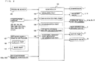
- Fig. 2 is a block diagram illustrating a configuration of the controller 101 according to Embodiment 1 of the present invention. Measurement values detected by various temperature sensors and pressure sensors are input to a measuring part 102. Based on information input, an operation control part 103 controls the compressor 1, the solenoid valve 22, the four-way valves 3 and 13, the heat source air-sending device 5, the heat source pressure reducing mechanism 6, the indoor pressure reducing mechanisms 8a and 8b, the water pump 17, and the like.
- the controller 101 also includes a communication part 104 which is capable of inputting communication data information from communication means, such as a telephone line, a LAN line, or a radio, and outputting information to an external device.
- the communication part 104 receives a hot water supply instruction (hot water supply ON/hot water supply OFF) output from a hot water supply remote controller 107, a set hot water discharge temperature, and the like, and inputs the received instruction, temperature, and the like to the controller 101.
- the communication part 104 receives a cooling instruction (cooling ON/OFF) or a heating instruction (heating ON/OFF) output from air-conditioning remote controllers 108a and 108b, and inputs the instructions to the controller 101.
- a hot water supply demand is input to the controller 101 automatically when the amount of hot water storage in the hot water storage tank 19 becomes lower than or equal to a predetermined value, for example, when the amount of hot water storage becomes less than or equal to 50 percent.
- the controller 101 also includes a hot water storage amount calculation part 105 which calculates the amount of hot water storage of the hot water storage tank 19.
- the controller 101 includes an additional exhaust heat recovery determination part 106 which determines whether or not to execute a simultaneous cooling and hot water supply operation in the case where there is a cooling load, that is, the status is cooling ON, and there is no hot water supply demand.
- the hot water supply remote controller 107 includes a display part 109 which displays the operation state and an input part 110 which inputs an instruction from a user on the refrigeration cycle apparatus 100.
- the hot water storage amount calculation part 105 calculates the amount of hot water storage by, for example, the way to be described below. First, the hot water storage tank 19 is divided in a height direction by individual instalment locations of the temperature sensors 211a to 211d, which are provided in the height direction of the hot water storage tank 19. Then, based on measurement data of the temperature sensors 211 at the top end and the bottom end of the individual divided sections measured by the measuring part 102, the hot water storage calculation part 105 calculates an average temperature for the individual divided sections. As the average temperature, the highest section uses the temperature of the temperature sensor 211 at the bottom end, and the lowest section uses the temperature of the temperature sensor 211 at the top end.
- the heat quantity of hot water storage in each of the divided sections is estimated by multiplying the amount of hot water and the specific heat of water in each of the divided sections with a value obtained by subtracting the tap water temperature from the average temperature.
- the estimated heat quantities of hot water storage in the individual divided sections are added up, and the obtained value is defined as the heat quantity of hot water storage in the hot water storage tank 19.
- the amount of hot water in each of the divided sections is obtained by dividing the internal volume of the hot water storage tank 19 by a value obtained by adding 1 to the number of the temperature sensors 211 installed.
- tap water is fixed at, for example, 15 degrees Celsius.
- the amount of hot water storage in the case where all of the measurement values of the temperature sensors 211a to 211d are at the hot water discharge temperature is set to 100%.
- the amount of hot water storage is obtained by dividing the heat quantity of hot water storage obtained from the temperature sensors 211a to 211d of the measurement values by the heat quantity of hot water storage in the case where the amount of hot water storage is 100%.
- the refrigeration cycle apparatus 100 performs control of equipment equipped in the heat source unit 301, the branch unit 302, the indoor units 303a and 303b, and the hot water supply unit 304 in accordance with air-conditioning loads demanded by the indoor units 303a and 303b and a hot water supply demand by the hot water supply unit 304.
- the refrigeration cycle apparatus 100 executes a cooling operation mode A, a heating operation mode B, a hot water supply operation mode C, and a simultaneous cooling and hot water supply operation mode D. Operational procedure for each of the operation modes will be described below.
- the cooling operation mode A will be described.
- the four-way valve 3 connects the discharge side of the compressor 1 with the gas side of the heat-source-side heat exchanger 4, and connects the suction side of the compressor 1 with the water heat exchanger 16.
- the four-way valve 13 connects the suction side of the compressor 1 with each of the gas sides of the indoor-side heat exchangers 10a and 10b.
- the solenoid valve 22 is closed.
- the heat source pressure reducing mechanism 6 is at a maximum opening degree (fully opened) and the hot water supply pressure reducing mechanism 21 is at a minimum opening degree (fully closed).
- a high-temperature, high-pressure gas refrigerant discharged from the compressor 1 flows into the heat-source-side heat exchanger 4 via the oil separator 2 and the four-way valve 3, exchanges heat with outdoor air, and turns into a high-pressure liquid refrigerant. Then, the refrigerant flows out of the heat-source-side heat exchanger 4, and flows through the heat source pressure reducing mechanism 6. After that, the refrigerant flows out of the heat source unit 301, flows into the branch unit 302 via the indoor liquid extension main pipe 7, is decompressed by the indoor pressure reducing mechanisms 8a and 8b into a low-pressure, two-phase refrigerant, and flows out of the branch unit 302.
- the refrigerant then flows into the indoor units 303a and 303b via the indoor liquid extension branch pipes 9a and 9b, cools indoor air at the indoor-side heat exchanger 8, and turns into a low-pressure gas refrigerant. Then, the refrigerant flows out of the indoor units 303a and 303b, passes through the indoor gas extension branch pipes 11a and 11b, the branch unit 302, and the indoor gas extension main pipe 12, flows into the indoor unit 301, passes through the four-way valve 13, flows through the accumulator 14, and is again sucked into the compressor 1.
- the hot water supply unit 304 is suspended, and therefore, no refrigerant flows in a portion between the hot water supply pressure reducing mechanism 21 and the four-way valve 3, which is filled with a gas-phase refrigerant.
- Opening degrees of the indoor pressure reducing mechanisms 8a and 8b are controlled in total so that the degree of subcooling of the heat-source-side heat exchanger 4 is a predetermined value.
- the degree of subcooling of the heat-source-side heat exchanger 4 is a value obtained by subtracting the temperature detected by the temperature sensor 205 from a saturated liquid temperature at a pressure detected by the pressure sensor 201.
- the operation frequency of the compressor 1 is controlled so that the evaporating temperature is a predetermined value.
- the evaporating temperature is a temperature detected by the temperature sensors 206a and 206b.
- the heat source air-sending device 5 is controlled so that the condensing temperature is a predetermined value.
- the condensing temperature is a saturated gas temperature at a pressure detected by the pressure sensor 201.
- the four-way valve 3 connects the discharge side of the compressor 1 with the gas side of the water heat exchanger 16, and connects the suction side of the compressor 1 with the gas side of the heat-source-side heat exchanger 4.
- the four-way valve 13 connects the discharge side of the compressor 1 with each of the gas sides of the indoor heat exchangers 10a and 10b.
- the solenoid valve 22 is closed.
- the outdoor pressure reducing mechanism 6 is at a maximum opening degree (fully opened) and the hot water supply pressure reducing mechanism 21 is fixed to such an opening degree that a refrigerant does not stay in a portion between the hot water supply gas extension main pipe 15 and the hot water supply liquid extension main pipe 20.
- the refrigerant flows out of the indoor units 303a and 303b, flows into the branch unit 302 via the indoor liquid extension branch pipes 9a and 9b, is decompressed by the indoor pressure reducing mechanisms 8a and 8b, and turns into a low-pressure, two-phase refrigerant.
- the refrigerant flows out of the branch unit 302, flows into the heat source unit 301 via the indoor liquid extension main pipe 7, passes through the heat source pressure reducing mechanism 6, flows into the heat-source-side heat exchanger 4, exchanges heat with outdoor air, and turns into a low-pressure gas refrigerant.
- the gas refrigerant flows out of the heat-source-side heat exchanger 4, passes through the four-way valve 3, flows through the accumulator 14, and is again sucked into the compressor 1.
- the hot water supply unit 304 is suspended, and therefore, no refrigerant flows in a portion between the four-way valve 3 and the hot water supply pressure reducing mechanism 21, which is filled with a gas-phase refrigerant.
- Opening degrees of the indoor pressure reducing mechanisms 8a and 8b are controlled so that the degree of subcooling of the indoor-side heat exchangers 10a and 10b is a predetermined value.
- the degree of subcooling of the indoor-side heat exchangers 10a and 10b is a value obtained by subtracting the temperature detected by the temperature sensors 206a and 206b from a saturated liquid temperature detected by the pressure sensor 201.
- the operation frequency of the compressor 1 is controlled so that the condensing temperature is a predetermined value.
- the condensing temperature is a saturated gas temperature at a pressure detected by the pressure sensor 201.
- the heat source air-sending device 5 is controlled so that the evaporating temperature is a predetermined value.
- the evaporating temperature is a temperature detected by the temperature sensor 205.
- the hot water supply operation mode C the four-way valve 3 connects the discharge side of the compressor 1 with the gas side of the water heat exchanger 16, and connects the suction side of the compressor 1 with the gas side of the heat-source-side heat exchanger 4.
- the four-way valve 13 connects the suction side of the compressor 1 with each of the gas sides of the indoor heat exchangers 10a and 10b.
- the solenoid valve 22 is closed.
- the indoor pressure reducing mechanisms 8a and 8b are at a minimum opening degree (fully closed) and the hot water supply pressure reducing mechanism 21 is at a maximum opening degree (fully opened).
- the refrigerant passes through the hot water supply pressure reducing mechanism 21, is decompressed by the heat source pressure reducing mechanism 6, and turns into a low-pressure, two-phase refrigerant.
- the refrigerant flows into the heat-source-side heat exchanger 4, cools outdoor air, and turns into a low-pressure gas refrigerant.
- the refrigerant flows out of the outdoor heat exchanger 4, passes through the accumulator 14 via the four-way valve 3, and is sucked into the compressor 1 again.
- the indoor units 303a and 303b are suspended, and therefore, no refrigerant flows in a portion between the indoor liquid extension main pipe 7 and the four-way valve 13, which is filled with a gas-phase refrigerant.
- the opening degree of the heat source pressure reducing mechanism 6 is controlled so that the degree of subcooling of the water heat exchanger 16 is a predetermined value.
- the degree of subcooling of the water heat exchanger 16 is a value obtained by subtracting a temperature detected by the temperature sensor 209 from a saturated liquid temperature at a pressure detected by the pressure sensor 201.
- the pressure sensor 201 and the temperature sensor 209 operate as degree-of-subcooling detection means of the water heat exchanger 16.
- the frequency of the compressor 1 is controlled to a maximum frequency.
- the condensing temperature is a saturated gas temperature at a pressure detected by the pressure sensor 201.
- the heat source air-sending device 5 is controlled so that the evaporating temperature is a predetermined value.
- the evaporating temperature is a temperature detected by the temperature sensor 205.
- the refrigeration cycle apparatus 100 is capable of independently performing indoor cooling, heating, and hot water supply. Specifically, through a cooling instruction (cooling ON/OFF) or a heating instruction (heating ON/OFF) selected by the indoor units 303a and 303b, and a hot water supply instruction (hot water supply ON/OFF) by the hot water supply unit 304, it is possible to operate the cooling operation mode A, the heating operation mode B, and the hot water supply operation mode C. Further, the refrigeration cycle apparatus 100 may be in the cooling-ON state of the indoor units 303a and 303b and the hot-water-supply-ON state of the hot water supply unit 304, at the same time.
- the four-way valve 3 connects the discharge side of the compressor 1 with the gas side of the water heat exchanger 16, and connects the suction side of the compressor 1 with the gas side of the heat-source-side heat exchanger 4.
- the four-way valve 13 connects the suction side of the compressor 1 with each of the gas sides of the indoor heat exchangers 10a and 10b.
- the solenoid valve 22 is closed.
- the hot water supply pressure reducing mechanism 21 is at a maximum opening degree (fully opened).
- a high-temperature, high-pressure gas refrigerant discharged from the compressor 1 passes through the oil separator 2 and the four-way valve 3, flows out of the heat source unit 301, and flows into the hot water supply unit 304 via the hot water supply gas extension main pipe 15.
- the refrigerant flowing into the hot water supply unit 304 flows into the water heat exchanger 16, heats water supplied by the water pump 17, turns into a high-pressure liquid refrigerant, and flows out of the water heat exchanger 16.
- the refrigerant flows out of the hot water supply unit 304, flows into the heat source unit 301 via the hot water supply liquid extension main pipe 20, and after passing through the hot water supply pressure reducing mechanism 21, the refrigerant is divided into two flows: one flowing out of the heat source unit 301 and flows through the indoor liquid extension main pipe 7, and the other flowing into the heat source pressure reducing mechanism 6.
- the refrigerant that has flowed through the indoor liquid extension main pipe 7 flows into the branch unit 302, is decompressed by the indoor pressure reducing mechanisms 8a and 8b, turns into a low-pressure, two-phase refrigerant, and flows out of the branch unit 302.
- the refrigerant flows into the indoor units 303a and 303b via the indoor liquid extension branch pipes 9a and 9b, flows into the indoor heat exchangers 10a and 10b, cools indoor air, and turns into a low-pressure gas refrigerant.
- the refrigerant flowing through the heat source pressure reducing mechanism 6 is decompressed, turns into a low-pressure, two-phase refrigerant, flows into the heat-source-side heat exchanger 4, cools outdoor air, and turns into a low-pressure gas refrigerant. Then, the refrigerant merges with the refrigerant that flows into the indoor liquid extension main pipe 7 via the four-way valve 3. The merged refrigerant passes through the accumulator 14 and is sucked into the compressor 1 again.
- control modes of the simultaneous cooling and hot water supply operation mode D include a cooling-prioritized state (cooling-prioritized mode) and a hot-water-supply-prioritized state (hot-water-supply-prioritized mode).
- the cooling-prioritized state In the cooling-prioritized state, an operation is performed in accordance with a cooling load, and no heat is exhausted. Therefore, the cooling-prioritized state has a higher energy-saving performance than the hot-water-supply-prioritized state.
- the hot-water-supply-prioritized state In the hot-water-supply-prioritized state, an operation is performed in accordance with a hot water supply demand, and completion of hot water supply is achieved in a short time. Therefore, the hot-water-supply-prioritized state has a high tolerance to running out of hot water. Considering those characteristics, it is desired to basically operate in the cooling-prioritized state to aim for a high energy-saving performance.
- Fig. 3 is a diagram illustrating the state of selection between the cooling-prioritized state and the hot-water-supply-prioritized state with respect to the load balance between cooling and hot water supply.
- a cooling-prioritized operation is selected in the case where the cooling load is large and the heat quantity of cooling is greater than the heat quantity of hot water supply.
- a hot-water-supply-prioritized operation is selected in the case where the amount of hot water storage is small and the heat quantity of hot water supply is greater than the heat quantity of cooling. That is, depending on the relationship between the cooling load and the hot water supply load, the selection of the control mode between the cooling-prioritized mode and the hot-water-supply-prioritized mode is made.
- Fig. 4 is a diagram illustrating a control method of equipment in the cooling-prioritized state and the hot-water-supply-prioritized state.
- the control method of equipment in each of the two states will be explained.
- the indoor pressure reducing mechanisms 8a and 8b are controlled so that the degree of subcooling of the water heat exchanger 16 is a predetermined value.
- the compressor 1 is controlled by the operation control part 103 so that the evaporating temperature is an evaporating temperature target value.
- the evaporating temperature is a temperature detected by the temperature sensors 206a and 206b (act as evaporating temperature detection means). Further, the evaporating temperature target value varies according to a maximum indoor temperature difference.
- the maximum indoor temperature difference is a maximum value of a temperature difference of the indoor units 303a and 303b.
- the temperature difference of the indoor units 303a and 303b is a value obtained by subtracting a set room temperature from temperatures detected by the temperature sensors 207a and 207b (act as indoor temperature measuring means). As the maximum indoor temperature difference increases, the cooling capacity is determined to be larger, and the evaporating temperature target value decreases.
- the heat source pressure reducing mechanism 6 is controlled to a minimum opening degree (fully closed) by the operation control part 103. This is because, since the compressor 1 operates in accordance with the cooling load, there is no need to exhaust heat by letting a refrigerant flow to the heat-source-side heat exchanger 4.
- the heat source air-sending device 5 is controlled by the operation control part 103 so that the temperature of the heat radiation plate is a target value.
- the temperature of the heat radiation plate is a temperature detected by the temperature sensor 212 (acts as heat radiation plate temperature detection means).
- the target value of the temperature of the heat radiation plate is set to a maximum temperature at which abnormalities do not occur in the electronic substrate for driving the compressor. This allows the air amount of the heat source air-sending device 5 to be a required minimum.
- the operation efficiency increases by the amount corresponding to a decrease in power input of the motor.
- the indoor pressure reducing mechanisms 8a and 8b are controlled in a manner similar to the cooling-prioritized mode.
- the compressor 1 is controlled by the operation control part 103 so that the frequency is fixed at a frequency, such as a maximum frequency or 75% of the maximum frequency. Since the compressor 1 is controlled to the fixed frequency independent of the cooling load, the cooling capacity may become excessive and indoor air may be cooled too much. Therefore, the comfort of the room may be impaired. To avoid this, it is necessary, by adjusting the opening degree of the heat source pressure reducing mechanism 6, to divide the refrigerant into two flows: one flowing into the indoor heat exchangers 10a and 10b; and the other flowing into the heat-source-side heat exchanger 4. That is, it is necessary to exhaust heat of excess cooling capacity by the heat-source-side heat exchanger 4.
- the opening degree of the heat source pressure reducing mechanism 6 is controlled by the operation control part 103 so that the evaporating temperature is an evaporating temperature target value. This aims at, since the compressor 1 operates in accordance with a hot water supply demand, exhausting excess cooling heat by letting a refrigerant flow to the heat-source-side heat exchanger 4.
- a predetermined cooling capacity of the indoor-side heat exchangers 10a and 10b is secured.
- the evaporating temperature target value varies according to a maximum indoor temperature difference. As the maximum indoor temperature difference increases, the cooling capacity is determined to be larger, and the evaporating temperature target value decreases.
- the heat source pressure reducing mechanism 6 When the heat source pressure reducing mechanism 6 is opened, the ratio of the cooling capacity treated by the heat-source-side heat exchanger 4 increases, and thereby the evaporating temperature increases. In contrast, when the heat source pressure reducing mechanism 6 is throttled, the evaporating temperature decreases. In the cooling-prioritized state, the evaporating temperature is controlled by the compressor 1, while in the hot-water-supply-prioritized state, the evaporating temperature is controlled by the heat source pressure reducing mechanism 6. Therefore, the cooling capacity provided to the indoor-side heat exchangers 10a and 10b can be adjusted. Therefore, even if the operation frequency of the compressor 1 is increased to avoid running out of hot water, a state in which a room is cooled too much can be prevented, and the comfort of the room may not be impaired.
- the rotation speed of the heat source air-sending device 5 is controlled by the operation control part 103 so that the temperature of the heat radiation plate is a target value. Further, when the degree of superheat of the heat-source-side heat exchanger 4 is lower than or equal to a predetermined value, for example, 2 degrees Celsius or below, the rotation speed of the heat source air-sending device 5 is increased and the amount of air is thereby increased so that the degree of superheat is equal to or higher than the predetermined value.
- a predetermined value for example, 2 degrees Celsius or below
- the degree of superheat of the heat-source-side heat exchanger 4 is a value obtained by subtracting a temperature detected by the temperature sensor 205 from a temperature detected by the temperature sensor 203 (the temperature sensor 203 and the temperature sensor 205 act as heat-source-side degree-of-superheat detection means).
- the degree of superheat of the heat-source-side heat exchanger 4 is not secured at or over the predetermined value, a large portion is occupied by a two-phase refrigerant with high heat-transfer performance, which means that heat of excess cooling capacity is not exhausted efficiently.
- the amount of air sent from the heat source air-sending device 5 is increased so as to heat the refrigerant up until it turns into a gas phase and to secure the required amount of exhaust heat.
- the opening degree of the heat source pressure reducing mechanism 6 is controlled by the operation control part 103 so that the degree of superheat of the heat-source-side heat exchanger 4 is the predetermined value.
- the refrigerant flowing through the indoor heat exchangers 10a and 10b and the refrigerant flowing through the heat-source-side heat exchanger 4 merge together and then the merged flow flows into the accumulator.
- the degree of superheat at the inlet of the accumulator is zero in a steady state.
- there is a degree of superheat at the heat-source-side heat exchanger 4 there is no degree of superheat at the indoor heat exchangers 10a and 10b.
- there is a degree of superheat at the indoor heat exchangers 10a and 10b there is no degree of superheat at the heat-source-side heat exchanger 4.
- the degree of superheat is at or over a predetermined value, for example, 2 degrees Celsius or more, at both the indoor heat exchangers 10a and 10b, it is assumed that the degree of superheat of the heat-source-side heat exchanger 4 is zero, and therefore, the rotation speed of the heat source air-sending device 5 is controlled by the operation control part 103 so that the degree of superheat of any of the indoor heat exchangers 10a and 10b is lower than or equal to 2 degrees Celsius.
- a predetermined value for example, 2 degrees Celsius or more
- the degree of superheat of the indoor heat exchangers 10a and 10b is a value obtained by subtracting a temperature detected by the temperature sensors 206a and 206b from a temperature detected by the temperature sensors 208a and 208b.
- the temperature sensors 208a, 208b, 206a, and 206b act as indoor degree-of-superheat detection means.
- the degree of superheat of the indoor heat exchangers 10a and 10b is decreased.
- the degree of superheat of the indoor heat exchangers 10a and 10b is increased.
- the opening degree of the heat source pressure reducing mechanism 6 is controlled by the operation control part 103 so that the degree of superheat of the heat-source-side heat exchanger 4 is the predetermined value.
- Fig. 5 includes schematic diagrams illustrating changes of operation states with respect to the opening degree of the heat source pressure reducing mechanism 6 in the hot-water-supply-prioritized state.
- Fig. 5 uses the refrigeration cycle apparatus 100 of around 6HP as an example.
- specifications of the indoor units 303a and 303b are the same and the cooling loads are also the same between the indoor units 303a and 303b.
- the opening degree of the heat source pressure reducing mechanism 6 increases, the cooling capacity decreases, and the amount of exhaust heat increases. Further, since the ratio of the quantity of heat treated by the heat-source-side heat exchanger 4 increases, the evaporating temperature rises and the hot water supply capacity also increases.
- the opening degrees of the indoor pressure reducing mechanisms 8a and 8b reach a lower limit, thus becoming incapable of further throttling the opening. Consequently, the degree of subcooling of the water heat exchanger 16 is decreased. The decrease in the degree of subcooling of the water heat exchanger 16 is not a desirable state as it degrades the operation efficiency. Further, when the opening degrees of the indoor pressure reducing mechanisms 8a and 8b are at the lower limit and further throttling is impossible, the flow rate of the refrigerant in the indoor heat exchangers 10a and 10b cannot be reduced even if the opening degree of the heat source pressure reducing mechanism 6 is increased.
- the opening degree of the heat source pressure reducing mechanism 6 is minimum in the air-conditioning-prioritized mode, when a selection is made and the control mode is switched from the air-conditioning-prioritized mode to the hot-water-supply-prioritized mode, it is necessary to set an appropriate initial opening degree so as not to impair the stability of the refrigeration cycle.
- the amount of exhaust heat treated by the heat-source-side heat exchanger 4 is estimated, based on the total capacity of the indoor units 303a and 303b which are in the cooling-ON state and the capacity of the hot water supply unit 304 which is in the hot-water-supply-ON state.
- the capacities of the indoor units 303a and 303b, which are in the cooling-ON state, are 3.5 kW and 2.5 kW
- the capacity of the hot water supply unit 304 is 18 kW
- the total opening degree at this time is 160 pulses (the opening degree of one of the indoor pressure reducing mechanisms 8a and 8b is within the range between 32 pulses and 480 pulses)
- the total Cv value at this time is 0.034
- the opening degree of the heat source pressure reducing mechanism 6 can be obtained from the Cv value of the calculation result.
- the amount of exhaust heat decreases by the amount of input of the compressor.
- an error occurs.
- an error at the setting of the initial opening degree can be fed back by regular control, and therefore, there would be no need to take it into account.
- the capacities of the indoor units 303a and 303b which are in the cooling-ON state and the hot water supply unit 304 which is in the hot-water-supply-ON state, are obtained by the communication part 104 of the controller 101.
- the operation frequency of the compressor 1 is controlled to be fixed.
- the value that is controlled to be fixed may be set slightly lower than the maximum frequency, for example, at 75% of the maximum frequency, aiming at a higher operation efficiency. If the cooling load is large at this time, there is a possibility that a room is not cooled due to the short of cooling heat. Control corresponding to such a case will be described below.
- control mode is the air-conditioning-prioritized mode
- the control mode when the control mode is switched to the hot-water-supply-prioritized mode after the hot-water-supply-ON duration passes a predetermined time, if the current frequency of the compressor is higher than the frequency of the compressor set in the hot-water-supply-prioritized mode, the air-conditioning-prioritized mode is maintained.
- the control mode is switched to the hot-water-supply-prioritized mode. Further, in the case where the control mode is the hot-water-supply-prioritized mode, when the opening degree of the heat source pressure reducing mechanism 6 reaches the lower limit, and the evaporating temperature is equal to or higher than the evaporating temperature target value even though there is little amount of exhaust heat, the operation frequency of the compressor 1 is increased so that the evaporating temperature is the evaporating temperature target value.
- the shortage of cooling heat at the hot-water-supply-prioritized time can be avoided, and a state in which the room is not cooled is prevented.
- the state in which the room is not cooled is prevented, even when the operation frequency of the compressor is not fixed to the maximum frequency at the hot-water-supply-prioritized time, because switching between control modes and control of the frequency of the compressor are performed in accordance with the magnitude of the cooling load when the cooling load is high.
- the lower limit of the opening degree of the heat source pressure reducing mechanism 6 mentioned here indicates a minimum value of the opening degree specified by normal operation control.
- the indoor units 303a and 303b which are in the cooling-ON state
- the indoor units 303a and 303b enter a cooling-thermo-OFF state.
- the opening degrees of the indoor pressure reducing mechanisms 8a and 8b reach the lower limit, so that a refrigerant does not flow to the indoor heat exchangers 10a and 10b. This prevents the room from being cooled further.
- the indoor units 303a and 303b enter a cooling-thermo-ON state.
- the indoor pressure reducing mechanisms 8a and 8b are opened, so that a refrigerant flows to the indoor heat exchangers 10a and 10b.
- both the indoor units 303a and 303b are in the cooling-thermo-OFF state in the cooling operation mode A, there is no room to be cooled, and the operation stops accordingly.
- the simultaneous cooling and hot water supply operation mode D even if both the indoor units 303a and 303b are in the cooling-thermo-OFF state, the operation does not stop because of the hot water supply unit 304, and the mode is switched to the hot water supply operation mode C.
- the operation control part 103 of the controller 101 performs control so that the temperature for the cooling-thermo-OFF state is set lower than the temperatures in the cooling operation mode A by 1 degree Celsius or more, and the temperature for the cooling-thermo-ON state is set higher than the temperatures in the cooling operation mode A by 1 degree Celsius or more. That is, in the simultaneous cooling and hot water supply operation mode D, when the indoor air temperature becomes lower than the set temperature by 2.5 degrees Celsius or more, then the cooling-thermo-OFF state is entered, and after that, when the indoor air temperature becomes higher than the set temperature by 1.5 degrees Celsius or more, then the cooling-thermo-ON state is entered.
- frequent switching between the simultaneous cooling and hot water supply operation mode D and the hot water supply operation mode C can be suppressed, ensuring a stable operation state. Therefore, the reliability of product quality can be improved.
- a selection between the air-conditioning-prioritized mode and the hot-water-supply-prioritized mode may use a duration, such as two hours, as an index, as described above.
- a method may be used in which the operation control part 103 makes a change based on the amount of hot water storage.
- Fig. 6 illustrates a case where a selection between the air-conditioning-prioritized mode and the hot-water-supply-prioritized mode is performed based on the amount of hot water storage. When the amount of hot water storage is between 100% and 50%, the amount of hot water is large, and there is little risk of running out of hot water.
- an operation is performed in the air-conditioning-prioritized mode as a control mode.
- the amount of hot water storage is between 50% and 0%, the amount of hot water is small, and there is a risk of running out of hot water. Therefore, an operation is performed in the hot-water-supply-prioritized mode as a control mode. Since the amount of hot water is used as an index for determination, it is possible to assess the risk of running out of hot water with accuracy and to properly grasp an area of a small risk of running out of hot water. Thus, through an air-conditioning-prioritized mode, the operation efficiency is enhanced, and thereby energy saving can be achieved.
- the compressor In the hot-water-supply-prioritized mode, the compressor is operated at a fixed operation frequency. The higher the fixed operation frequency at that time, the faster hot water is boiled. However, it is characterized by the fact that the operation efficiency is decreased. In order to enhance the operation efficiency as much as possible even in the hot-water-supply-prioritized mode, it is recommended to operate at an operation frequency as low as possible.
- the amount of hot water storage can be used. When the hot water storage amount is between 50% and 25%, it is determined that it will be a while before hot water runs out. Therefore, the compressor is set to operate at a fixed capacity of 75%.
- the compressor is set to operate at a capacity of 100%. This allows an operation efficiency kept as high as possible even in the hot-water-supply-prioritized mode. Further, since the amount of hot water storage is used as an index for determination, it is possible to assess the risk of running out of hot water with accuracy. This enhances the operation efficiency in the hot-water-supply-prioritized mode in an area of a small risk of running out of hot water. Thus, energy saving can be achieved.
- An operation efficiency of 100% means that, for example, when the maximum frequency of the compressor 1 is 100 Hz, the compressor 1 operates at 100 Hz.
- a compressor capacity of 75% means that the compressor operates at 75 Hz.
- Thresholds of the air-conditioning-prioritized mode and the hot-water-supply-prioritized mode set on the basis of the amount of hot water storage as illustrated in Fig. 6 may be varied freely by a user.
- the amount of hot water storage for the air-conditioning-prioritized mode may be set to a range from 60% to 100%, and the amount of hot water storage for the hot-water-supply-prioritized mode may be set to a range from 0% to 60%.
- the amount of hot water storage for the air-conditioning-prioritized mode may be set to a range from 0% to 100%, and for a user who consumes a large amount of hot water, the amount of hot water storage for the hot-water-supply-prioritized mode may be set to a range from 0% to 100%.
- a prioritized operation selectively in accordance with user's consumption amount of hot water. This secures tolerance to running out of hot water while increasing energy saving.
- the operation capacity of the compressor at the hot-water-supply-prioritized time may set by a user using the hot water supply remote controller 107.
- the compressor may be configured to operate at a capacity of 90% when the amount of hot water storage is within a range from 0% to 40%
- the compressor may be configured to operate at a capacity of 70% when the amount of hot water storage is within a range from 40% to 60%.
- indexes of thresholds for the hot-water-supply-prioritized mode and the air-conditioning-prioritized mode may be displayed as rapid hot water supply, normal hot water supply, and mild hot water supply (a relation amount of switching of a priority threshold).
- the amount of hot water storage is set to a range from 0% to 75% for the hot-water-supply-prioritized mode and to a range from 75% to 100% for the air-conditioning-prioritized mode.
- the amount of hot water storage is set to a range from 0% to 50% for the hot-water-supply-prioritized mode and to a range from 50% to 100% for the air-conditioning-prioritized mode.
- the amount of hot water storage is set to a range from 0% to 25% for the hot-water-supply-prioritized mode and to a range from 25% to 100% for the air-conditioning-prioritized mode.
- indexes of the capacity of the compressor at the hot-water-supply-prioritized time may be displayed as large capacity, normal, and energy-saving (a relation amount of switching of the hot-water-supply-prioritized operation).
- the capacity of the compressor may be set to 100% for large capacity, the capacity of the compressor may be set to 80% for normal, and the capacity of the compressor may be set to 60% for energy saving.
- a threshold for selecting and switching the capacity of the compressor in the hot-water-supply-prioritized mode may be set in the middle of the hot-water-supply-prioritized range, and a capacity of the compressor may be specified for each portion.
- the same capacity of the compressor may be specified for the entire hot-water-supply-prioritized range.
- the relation amount of switching of a priority threshold and the relation amount of switching of a hot-water-supply-prioritized operation are displayed on the display part 109 of the hot water supply remote controller 107, and may be input through the input part 110 by a user.
- a control method of equipment and the flow direction of a refrigerant in the second simultaneous cooling and hot water supply operation mode D are the same as those in the simultaneous cooling and hot water supply operation mode D.
- the simultaneous cooling and hot water supply operation mode D has an air-conditioning-prioritized mode and a hot-water-supply-prioritized mode as control modes
- the second simultaneous cooling and hot water supply operation mode E has only an air-conditioning-prioritized mode as a control mode.
- An air-conditioning-prioritized control method in the second simultaneous cooling and hot water supply operation mode E is the same as that in the simultaneous cooling and hot water supply operation mode D.
- a cooling load is generated when the amount of hot water storage is not 100%, for example, about 70%, and cooling ON is set by the air-conditioning remote controllers 108a and 108b, cooling and hot water supply are performed simultaneously as the second simultaneous cooling and hot water supply operation mode E.
- an air-conditioning-prioritized mode is set as a control mode.
- cooling and hot water supply are performed simultaneously as the simultaneous cooling and hot water supply operation mode D, and the hot-water-supply-prioritized mode is set as a control mode.
- hot water supply is performed with high operation efficiency when there is no hot water supply demand and there is no worry about running out of hot water.
- An operation which is tolerant to running out of hot water is performed while hot water supply is demanded when there is worry about running out of hot water, thus achieving energy saving in a state where there is no worry about running out of hot water.
- an aspect in which the capacity of the compressor at the time when hot water supply is prioritized varies according to the amount of hot water storage may be added to this case. Accordingly, high operation efficiency can be achieved even when hot water supply is prioritized, thus achieving energy saving.
- the second simultaneous cooling and hot water supply operation mode E does not always achieve an efficiency higher than the cooling operation mode A.
- the cooling operation mode A may achieve an efficiency higher than the second simultaneous cooling and hot water supply operation mode E.
- Fig. 7 illustrates a change in the operation efficiency with respect to the condensing temperature in the cooling operation mode A and the second simultaneous cooling and hot water supply operation mode E (the air-conditioning-prioritized mode is set as a control mode).
- the operation efficiency is lower than that at a condensing temperature of 25 degrees Celsius or 30 degrees Celsius in the cooling operation mode A. That is, when the hot water discharge temperature is high, such as 50 degrees Celsius or 55 degrees Celsius, and the condensing temperature is high, such as 50 degrees Celsius or 55 degrees Celsius, if the outside air temperature is low or the cooling load is low, the cooling operation mode A, in which the condensing temperature is 25 degrees Celsius or 30 degrees Celsius, achieves an operation efficiency higher than the second simultaneous cooling and hot water supply operation mode E.
- Fig. 8 is a Mollier chart in the cooling operation mode A and the second simultaneous cooling and hot water supply operation mode E.
- the cooling operation mode A achieves an operation efficiency higher than the second simultaneous cooling and hot water supply operation mode E when the following conditions are satisfied.
- the right side When a calculation of COPc is performed for the right side, when COPc is 5 or more, the right side becomes 2.5 or less.
- a determination as to switching may be made based on whether or not the compression ratio is 2.5 times or more.
- the determination as to selection of an operation and switching between operations may be made only based on changes in the high pressures Pd1 and Pd2. That is, the determination as to switching between operation modes may be made according to the ratio of high pressure in the second simultaneous cooling and hot water supply operation mode E to high pressure in the cooling operation mode A.
- Fig. 9 is a flowchart illustrating a case where an operation mode is selected and switching between operation modes is performed when there is a cooling load and there is no hot water supply demand.
- An operation illustrated in Fig. 9 is performed by the additional exhaust heat recovery determination part 106 of the controller 101. Switching between operation modes in the case where there is no hot water supply demand will be explained below with reference to Fig. 9 .
- step S11 a determination as to the current operation status is made.
- high pressure P1 is acquired in step S12.
- the high pressure P1 is high pressure in the cooling operation mode A that is currently being operated and is the pressure detected by the pressure sensor 201.
- high pressure P2 is estimated in step S13.
- the high pressure P2 in the case of the second simultaneous cooling and hot water supply operation mode E is estimated as described below. That is, the hot water storage tank 19 employs a boiling method based on circulation and heating, and a heat medium flowing into the water heat exchanger 16 circulates through the water-side circuit 18 while increasing the temperature thereof by a predetermined temperature. That is, the outlet water temperature of the water heat exchanger 16 is equal to the temperature obtained by adding the predetermined temperature to the inlet water temperature, such as, for example, the temperature obtained by adding 5 degrees Celsius to the inlet water temperature.
- the condensing temperature of the high pressure Pd2 is usually substantially equal to the heat medium temperature of the outlet of the water heat exchanger.
- the condensing temperature of the high pressure Pd2 may be set to the temperature obtained by adding 5 degrees Celsius to the inlet water temperature of the water heat exchanger 16.
- the inlet water temperature of the water heat exchanger 16 is the temperature at the lowest portion of temperature sensors which detect the water temperature of the hot water storage tank 19, that is, the temperature detected by the temperature sensor 211d in Embodiment 1.
- the inlet water temperature may be fixed as the value of the temperature of normal water, for example, 15 degrees Celsius.
- a temperature sensor may be provided between the water pump 17 and the water heat exchanger 16, and the temperature detected by the temperature sensor may be defined as the inlet water temperature.
- the high pressure P2 is calculated from the obtained condensing temperature.
- the additional exhaust heat recovery determination part 106 includes second cooling and hot water supply high pressure estimation means for calculating the high pressure P2 as described above. Then, in step S14, it is determined whether or not Pd2 / Pd1 is smaller than or equal to a high pressure determination threshold M [-]. When Pd2 / Pd1 is smaller than or equal to the high pressure determination threshold M and the amount of hot water storage is smaller than a hot water storage amount determination threshold N, switching to the second simultaneous cooling and hot water supply operation mode E is performed in step S15. Based on results of the discussion above, 2.5 is obtained as M.
- N represents a threshold which permits the second simultaneous cooling and hot water supply operation mode E in which there is no hot water supply demand, and is set to, for example, 70. Furthermore, when Pd2 / Pd1 is equal to or greater than M or the amount of hot water storage is greater than N, the cooling operation mode A is maintained.
- step S11 When it is determined in step S11 that the current operation status is the second simultaneous cooling and hot water supply operation mode E, the process proceeds to step S16.
- the current operation status is determined to be the second simultaneous cooling and hot water supply operation mode E in step S11 when switching to the second simultaneous cooling and hot water supply operation mode E is performed in step S15 and the determination in step S11 is then made.
- step S16 the high pressure P2 is obtained.
- the high pressure P2 represents the second simultaneous cooling and hot water supply operation mode E that is currently being operated and the pressure detected by the pressure sensor 201.
- step S17 high pressure P1 is estimated.
- the high pressure P1 in the case of the cooling operation mode A is estimated as described below.
- the condensing temperature in the cooling operation mode A is obtained by adding a predetermined temperature to the outside air temperature. It is considered that switching to the second simultaneous cooling and hot water supply operation mode E in the processing of steps S12 to S15 is mainly performed when the cooling load is low.
- the predetermined temperature is about 5 degrees Celsius. That is, the pressure in the case where the condensing temperature is represented by a temperature obtained by adding 5 degrees Celsius to the outside air temperature is defined as the high pressure P1.
- the outside air temperature is the temperature detected by the temperature sensor 204.
- the condensing temperature is abnormally low when the outside air temperature is low, the condensing temperature is fixed at, for example, 25 degrees Celsius when the temperature obtained by adding 5 degrees Celsius to the outside air temperature is 25 degrees Celsius or below.
- the high pressure P1 is calculated from the obtained condensing temperature.
- the additional exhaust heat recovery determination part 106 includes cooling high pressure estimation means for calculating the high pressure P1 as described above. Then, in step S18, it is determined whether or not Pd2 / Pd1 is equal to or greater than the high pressure determination threshold M. When Pd2 / Pd1 is equal to or greater than M, switching to the cooling operation mode A is performed in step S19.
- the high pressure determination threshold M is set to "2.5" in the above explanation, the high pressure determination threshold M is not necessarily set to "2.5".
- the high pressure determination threshold M may be set to "2" or "3".
- the operation in the cooling operation mode A is more likely to be selected as the high pressure determination threshold M decreases, and the operation of the second simultaneous cooling and hot water supply operation mode E is more likely to be selected as the high pressure determination threshold M increases.
- the operation state in the cooling operation mode A before switching may be used.
- the current predetermined temperature is stored as a temperature difference between the condensing temperature and the outside air temperature and is used as the predetermined temperature to be used for the calculation in step S17.
- the condensing temperature is the saturation temperature of the pressure detected by the high pressure sensor 201
- the outside air temperature is the temperature detected by the temperature sensor 204.
- the flowchart illustrated in Fig. 9 may not be performed for 30 minutes.
- cooling operation mode A or the second simultaneous cooling and hot water supply operation mode E achieves a higher operation efficiency may be performed properly, and an operation with higher efficiency may be performed. Therefore, cooling heat and hot water supply heat may be achieved with high operation efficiency, and energy saving may thus be achieved.
- the hot water storage amount threshold for the hot water storage tank 19 for the flowchart illustrated in Fig. 9 may be set to 70%, and a user may change the amount of hot water storage to, for example, 60% or 80%, using the hot water supply remote controller 107.
- a large hot water storage amount threshold hot water may be obtained with high operation frequency. Therefore, energy saving may be achieved.
- a small hot water storage amount threshold excess water boiling may be prevented.
- the quantity of heat may be managed in accordance with the style of hot water usage by the user. Therefore, the amount of boiling water is optimized, and unnecessary additional boiling may be avoided or hot water may be obtained by a high-efficiency operation. Thus, energy saving is achieved.
- the method for inputting the hot water storage amount threshold by a user is not necessarily performed by designating percentage.
- the hot water storage amount threshold may be designated by a user-friendly way, such as designation of a large amount (80%), a medium amount (60%), or a small amount (40%).
- the hot water supply unit 304 employs a boiling method based on circulation and heating. Therefore, it is estimated that the operation described below is performed when the flowchart illustrated in Fig. 9 is performed.
- Low-temperature tap water is present in a lower part of the hot water storage tank 19, and it is determined in step S13 that the high pressure P2 is a pressure at a condensing temperature, which is obtained by adding 5 degrees Celsius to tap water. Therefore, when the amount of hot water storage is below N, even if the outside air temperature is low or the cooling load is low, switching to the second simultaneous cooling and hot water supply operation mode E is performed almost certainly.
- step S19 After the operation is performed for a while, when the water temperature at the bottom of the tank is increased a plurality of times, the condensing temperature increases. Then, if the outside air temperature is low or the cooling load is low, the cooling operation mode A is selected again in step S18. The operation is maintained by switching in step S19.
- Fig. 10 is a refrigerant circuit diagram of a refrigeration cycle apparatus 200 according to Embodiment 2 of the present invention.
- the refrigerant circuit configuration of the refrigeration cycle apparatus 200 will be explained with reference to Fig. 10 .
- the same parts as those in Embodiment 1 will be referred to with the same reference signs and differences from Embodiment 1 will be mainly explained.
- a hot water supply unit 304b is connected, in place of the hot water supply unit 304.
- the hot water supply unit 304b includes the plate water heat exchanger 16, the water-side circuit 27, the water pump 17, and the hot water storage tank 19.
- the water-side circuit 27 allows connection between the water heat exchanger 16 and the hot water storage tank 19, and water of the hot water storage tank 19 circulates through the water-side circuit 27.
- the water pump 17 has a function of causing water in the hot water storage tank 19 to circulate through the water-side circuit 27 and is configured to be capable of varying the flow rate of water supplied to the water heat exchanger 16.
- the hot water storage tank 19 is of a full water type. Hot water is discharged from the top of the tank according to a hot water supply demand on the load side, and low-temperature tap water corresponding to the decreased amount of hot water is supplied from the bottom of the tank.
- the water pump 17 sends water in the hot water storage tank 19 through the connection point 28 at the bottom of the tank.
- the water then passes through the water pump 17 and is heated by a refrigerant in the water heat exchanger 16, thus increasing the temperature thereof.
- the heated water passes through the connection point 29 at the top of the tank and flows into the hot water storage tank 19. In accordance with this process, water is boiled in the hot water storage tank 19.
- Hot water is discharged out of the top of the hot water storage tank 19, and low-temperature tap water is supplied through the bottom of the hot water storage tank 19. Therefore, low-temperature water is present in a lower part of the tank.
- water flows out through the connection point 28 at the bottom of the tank and water flows in through the connection point 29 at the top of the tank. Therefore, if the temperature of water flowing in does not exceed a hot water discharge temperature, the temperature of water in an upper part of the tank decreases.
- water needs to be increased to a set hot water discharge temperature by a single heat exchange operation at the water heat exchanger 16. This boiling method is called once-through heating.
- the flow rate of the water pump 17 is lower than Embodiment 1. For example, if the set hot water discharge temperature is 55 degrees Celsius and the temperature of water in a lower part of the hot water storage tank 19 is 15 degrees Celsius, the inlet water temperature of the water heat exchanger 16 in the water-side circuit 27 is 15 degrees Celsius and the outlet water temperature of the water heat exchanger 16 in the water-side circuit 27 is 55 degrees Celsius.
- Embodiment 2 The operation modes used in Embodiment 2 are the cooling operation mode A, the heating operation mode B, the hot water supply operation mode C, the simultaneous cooling and hot water supply operation mode D, and the second simultaneous cooling and hot water supply operation mode E, as in Embodiment 1. Furthermore, control methods of equipment in the individual operation modes are similar to Embodiment 1 with the exception described below. That is, since, unlike Embodiment 1, boiling is performed by once-through heating in the hot water supply unit 304b in Embodiment 2, an operation method in execution of the flowchart illustrated in Fig. 9 differs between Embodiment 1 and Embodiment 2. More specifically, a method for estimating the high pressure P2 in the second simultaneous cooling and hot water supply operation mode E in step S13 differs between Embodiment 1 and Embodiment 2. This difference will be explained below.
- the flowchart of Fig. 9 illustrates selection of an operation mode when there is a cooling load and there is no hot water supply demand.
- the process illustrated in Fig. 9 is executed by the additional exhaust heat recovery determination part 106 of the controller 101.
- step S11 a determination as to the current operation status is performed.
- the high pressure P1 is acquired in step S12.
- the high pressure P1 is high pressure in the cooling operation mode A that is currently being operated and is the pressure detected by the pressure sensor 201.
- the high pressure P2 is estimated.
- the high pressure P2 in the case of the second simultaneous cooling and hot water supply operation mode E is estimated as described below.
- the boiling method for the hot water storage tank 19 is based on once-off heating, and water flowing into the water heat exchanger 16 reaches the hot water discharge temperature at the outlet of the water heat exchanger 16.
- the temperature of water at the outlet of the water heat exchanger 16 is also 55 degrees Celsius.
- the condensing temperature of the high pressure Pd2 since the condensing temperature of the high pressure Pd2 is normally substantially equal to the water temperature at the outlet of the water heat exchanger, the condensing temperature of the high pressure Pd2 may be defined as the hot water discharge temperature.
- the high pressure P2 is calculated based on the obtained condensing temperature.
- the additional exhaust heat recovery determination part 106 includes second cooling and hot water supply high pressure estimation means for calculating the high pressure P2 described above. Then, in step S14, it is determined whether or not Pd2 / Pd1 is smaller than or equal to a high pressure determination threshold M [-]. When Pd2 / Pd1 is smaller than or equal to M and the amount of hot water storage is smaller than a hot water storage amount determination threshold N, switching to the second simultaneous cooling and hot water supply operation mode E is performed in step S15. Based on results of the discussion above, 2.5 is obtained as the high pressure determination threshold M.
- the hot water storage amount determination threshold N is a threshold which permits the second simultaneous cooling and hot water supply operation mode E in the case where there is no hot water supply demand, and is set to, for example, 70. When Pd2 / Pd1 is equal to or greater than M and the amount of hot water storage is greater than N, the cooling operation mode A is maintained.
- step S11 When it is determined in step S11 that the operation mode is the second simultaneous cooling and hot water supply operation mode E, the process proceeds to step S16.
- step S16 For example, when the flow illustrated in Fig. 9 is executed after switching to the second simultaneous cooling and hot water supply operation mode E in step S15, the process proceeds to step S16.
- the processing of steps S16 to S19 are similar to those in Embodiment 1.
- the processing method in step S13 varies according to the boiling method. However, with the use of high pressure in the current operation status and the high pressure estimated from the outside air temperature or the water temperature, a determination as to whether the cooling operation mode A or the second simultaneous cooling and hot water supply operation mode E achieves higher operation efficiency may be made appropriately, and an operation with high efficiency may be performed. Therefore, cooling heat and hot water supply heat may be achieved with high operation frequency, thus achieving energy saving.
- the hot water supply unit 304b since the hot water supply unit 304b employs the boiling method based on once-through heating, the operation described below is estimated to be performed when the process illustrated by the flowchart of Fig. 9 is performed. It is determined in step S13 that the high pressure P2 is a pressure at which the condensing temperature is equal to the hot water discharge temperature. Therefore, when the condensing temperature in the cooling operation mode A is low due to a low outside air temperature, a low cooling load, or the like, the second simultaneous cooling and hot water supply operation mode E is not selected. In contrast, when the outside air temperature is high or the cooling load is high, the second simultaneous cooling and hot water supply operation mode E is selected, and an operation continues to be performed until the amount of hot water storage has reached 100%.
Landscapes
- Engineering & Computer Science (AREA)
- Mechanical Engineering (AREA)
- General Engineering & Computer Science (AREA)
- Physics & Mathematics (AREA)
- Thermal Sciences (AREA)
- Chemical & Material Sciences (AREA)
- Combustion & Propulsion (AREA)
- Life Sciences & Earth Sciences (AREA)
- Sustainable Development (AREA)
- Heat-Pump Type And Storage Water Heaters (AREA)
- Air Conditioning Control Device (AREA)
Claims (12)
- Kühlkreislaufvorrichtung, umfassend:eine oder mehrere Wärmequelleneinheiten (301), die jeweils einen Verdichter (1), dessen Betriebsfrequenz steuerbar ist, einen wärmequellenseitigen Wärmetauscher (4), eine Wärmequellenluft-Zuführungseinrichtung (5), die dem wärmequellenseitigen Wärmetauscher Außenluft zuführt, und einen Wärmequellendruck-Reduktionsmechanismus (6) beinhalten;eine Verzweigungseinheit (302), die einen Innendruckreduktionsmechanismus (8a, 8b) beinhaltet;eine oder mehrere Inneneinheiten, die jeweils einen Innenwärmetauscher (10a, 10b) beinhalten, der Innenluft kühlt oder erwärmt;eine oder mehrere Warmwasserzufuhreinheiten (304), die jeweils einen Warmwasserspeichertank (19), eine Wasserpumpe (17), einen Wasserwärmetauscher (16), der Wasser in dem Warmwasserspeichertank (19) erwärmt, und eine wasserseitige Schaltung (18), die den Warmwasserspeichertank, die Wasserpumpe und den Wasserwärmetauscher durch ein Rohr verbindet, beinhalten;einen Kühlkreislauf, in dem der Verdichter, der Wasserwärmetauscher, der Innendruckreduktionsmechanismus und der Innenwärmetauscher durch ein Rohr in dieser Reihenfolge verbunden sind;eine Abwärmeschaltung, die von zwischen dem Wasserwärmetauscher und dem Innendruckreduktionsmechanismus abzweigt, den Wärmequellendruck-Reduktionsmechanismus und den wärmequellenseitigen Wärmetauscher in dieser Reihenfolge durch ein Rohr verbindet und zwischen dem Innenwärmetauscher und dem Verdichter geschaltet ist; undeine Steuerung (101), die ein Betriebssteuerteil (103), das Betriebe von einzelnen Einheiten steuert, beinhaltet, wobeidas Betriebssteuerteil (103)einen gleichzeitigen Kühlungs- und Warmwasserzufuhr-Betriebsmodus beinhaltet, bei dem ein Kühlungsbetriebsmodus, bei dem ein Kühlmittel von dem Verdichter (1) dazu veranlasst wird, zu dem Innenwärmetauscher der Inneneinheit (303) mit einer Kühllast zu fließen, und ein Warmwasserzufuhr-Betriebsmodus, bei dem das Kühlmittel von dem Verdichter (1) dazu veranlasst wird, zu dem Wasserwärmetauscher der Warmwasserzufuhreinheit (304) mit einem Warmwasserzufuhrbedarf zu fließen, gleichzeitig durchgeführt werden,einen kühlungspriorisierten Modus, bei dem die Betriebsfrequenz des Verdichters (1) gemäß der Kühllast gesteuert wird, und einen warmwasserzufuhrpriorisierten Modus, bei dem die Betriebsfrequenz des Verdichters (1) gemäß dem Warmwasserzufuhrbedarf gesteuert wird, als Steuermodi des gleichzeitigen Kühlungs- und Warmwasserzufuhr-Betriebsmodus beinhaltet undden Steuermodus des gleichzeitigen Kühlungs- und Warmwasserzufuhr-Betriebsmodus zwischen dem kühlungspriorisierten Modus und dem warmwasserzufuhrpriorisierten Modus gemäß einer Beziehung zwischen der Kühllast und dem Warmwasserzufuhrbedarf schaltet und dadurch gekennzeichnet, dass:in einem Fall, in dem der Steuermodus des gleichzeitigen Kühlungs- und Warmwasserzufuhr-Betriebsmodus der kühlungspriorisierte Modus ist, wenn die Betriebsfrequenz des Verdichters (1) höher als eine Zielfrequenz in dem warmwasserzufuhrpriorisierten Modus ist, das Betriebssteuerteil (103) in den kühlungspriorisierten Modus eintritt undin einem Fall, in dem der Steuermodus der warmwasserzufuhrpriorisierte Modus ist, wenn ein Öffnungsgrad des Wärmequellendruck-Reduktionsmechanismus (6) bei einer unteren Grenze ist und eine Verdampfungstemperatur gleich oder höher als eine Zielverdampfungstemperatur ist, das Betriebssteuerteil (103) die Betriebsfrequenz des Verdichters (1) steuert, sodass die Verdampfungstemperatur die Zielverdampfungstemperatur ist.
- Kühlkreislaufvorrichtung nach Anspruch 1, wobei
die Steuerung (101) ferner ein Warmwasserspeichermengen-Berechnungsteil (105) beinhaltet, das konfiguriert ist, eine Menge an Warmwasserspeicherung in dem Warmwasserspeichertank (19) zu berechnen, und
das Betriebssteuerteil (103) ferner zwischen dem kühlungspriorisierten Modus und dem warmwasserzufuhrpriorisierten Modus, die Steuermodi des gleichzeitigen Kühlungs- und Warmwasserzufuhr-Betriebsmodus sind, gemäß der Menge an Warmwasserspeicherung auswählt und einen festen Betrag der Betriebsfrequenz des Verdichters (1) auswählt, wenn der warmwasserzufuhrpriorisierte Modus ausgewählt ist. - Kühlkreislaufvorrichtung nach Anspruch 1 oder 2, ferner umfassend:Innentemperaturmessmittel (207) zum Messen einer Innenlufttemperatur; undVerdampfungstemperaturerfassungsmittel (206) zum Erfassen einer Verdampfungstemperatur zwischen dem Innendruckreduktionsmechanismus (8) und dem Verdichter (1), wobeidas Betriebssteuerteil (103) fernerin dem warmwasserzufuhrpriorisierten Modus des gleichzeitigen Kühlungs- und Warmwasserzufuhr-Betriebsmodus einen Öffnungsgrad des Wärmequellendruck-Reduktionsmechanismus (6) steuert, sodass die Verdampfungstemperatur eine Zielverdampfungstemperatur ist, unddie Zielverdampfungstemperatur in Übereinstimmung mit einer maximalen Temperaturdifferenz zwischen der Innenlufttemperatur und einer festgelegten Temperatur der einen oder mehreren Inneneinheiten (303), die derzeit verwendet werden, festlegt.
- Kühlkreislaufvorrichtung nach Anspruch 3, ferner umfassend:eine Wärmeabstrahlungsplatte (31), die Wärme abführt, die von einem elektronischen Substrat erzeugt wird, das in der Wärmequelleneinheit (301) bereitgestellt ist; Wärmeabstrahlungsplattentemperatur-Erfassungsmittel (212) zum Erfassen einer Temperatur der Wärmeabstrahlungsplatte (31); und wärmequellenseitiges Überhitzungsgraderfassungsmittel (203, 205) zum Erfassen eines Überhitzungsgrads des wärmequellenseitigen Wärmetauschers (4) oder Innenüberhitzungsgrad-Erfassungsmittel (206, 208) zum Erfassen eines Überhitzungsgrads des Innenwärmetauschers (10), wobeidas Betriebssteuerteil (103) fernereine Drehgeschwindigkeit der Wärmequellenluft-Zuführungseinrichtung (5) in dem kühlungspriorisierten Modus des gleichzeitigen Kühlungs- und Warmwasserzufuhr-Betriebsmodus steuert, sodass die Wärmeabstrahlungsplattentemperatur geringer als oder gleich einer Wärmeabstrahlungsplatten-Zieltemperatur ist, die eine Temperatur ist, bei der das elektronische Substrat nicht beschädigt wird, unddie Drehgeschwindigkeit der Wärmequellenluft-Zuführungseinrichtung (5) in dem warmwasserzufuhrpriorisierten Modus des gleichzeitigen Kühlungs- und Warmwasserzufuhr-Betriebsmodus steuert, sodass die Wärmeabstrahlungsplattentemperatur geringer als oder gleich der Wärmeabstrahlungsplatten-Zieltemperatur ist und einer von einem Zustand, in dem der wärmequellenseitige Überhitzungsgrad gleich oder größer als ein vorbestimmter Wert ist, und einem Zustand, in dem der Innenüberhitzungsgrad kleiner als oder gleich einem vorbestimmten Wert ist, erzielt wird.
- Kühlkreislaufvorrichtung nach Anspruch 4, wobei:in einem Fall, in dem eine Drehgeschwindigkeit der Wärmequellenluft-Zuführungseinrichtung (5) in dem warmwasserzufuhrpriorisierten Modus des gleichzeitigen Kühlungs- und Warmwasserzufuhr-Betriebsmodus maximal ist,das Betriebssteuerteil (103) ferner Folgendes steuert,wenn der Überhitzungsgrad des wärmequellenseitigen Wärmetauschers (4) kleiner als oder gleich einem vorbestimmten Wert ist, den Öffnungsgrad des Wärmequellendruck-Reduktionsmechanismus (6), sodass der Überhitzungsgrad des wärmequellenseitigen Wärmetauschers (4) der vorbestimmte Wert ist oderwenn der Überhitzungsgrad des Innenwärmetauschers (10) gleich oder größer als der vorbestimmte Wert ist, den Öffnungsgrad des Wärmequellendruck-Reduktionsmechanismus (6), sodass der Überhitzungsgrad des Innenwärmetauschers (10) kleiner als oder gleich dem vorbestimmten Wert ist.
- Kühlkreislaufvorrichtung nach einem der Ansprüche 3 bis 5, ferner umfassend:Unterkühlungsgraderfassungsmittel (201, 209) zum Erfassen eines Unterkühlungsgrads des Wasserwärmetauschers (16), wobeiin dem warmwasserzufuhrpriorisierten Modus des gleichzeitigen Kühlungs- und Warmwasserzufuhr-Betriebsmodusdas Betriebssteuerteil (103) ferner, wenn Öffnungsgrade aller Innendruckreduktionsmechanismen (8) eine untere Grenze erreichen, den Öffnungsgrad des Wärmequellendruck-Reduktionsmechanismus (6) steuert, sodass der Unterkühlungsrad des Wasserwärmetauschers (16) ein vorbestimmter Wert ist.
- Kühlkreislaufvorrichtung nach einem der Ansprüche 3 bis 6, wobei
die Steuerung (101) ferner ein Kommunikationsteil (104) beinhaltet, das in der Lage ist, eine Kapazität der Inneneinheit (303) mit der Kühllast und eine Kapazität der Warmwasserzufuhreinheit (304) mit einem Warmwasserzufuhrbedarf über Kommunikation in die Steuerung (101) einzugeben, und
das Betriebssteuerteil (103) einen Anfangsöffnungsgrad des Wärmequellendruck-Reduktionsmechanismus (6) in Übereinstimmung mit der Kapazität der Inneneinheit (303), der Kapazität der Warmwasserzufuhreinheit (304) und einem Öffnungsgrad des Innendruckreduktionsmechanismus (8) bestimmt, wenn eine Auswahl des Steuermodus des gleichzeitigen Kühlungs- und Warmwasserzufuhr-Betriebsmodus von dem kühlungspriorisierten Modus zu dem warmwasserzufuhrpriorisierten Modus geschaltet wird. - Kühlkreislaufvorrichtung nach Anspruch 3,
wobei in dem gleichzeitigen Kühlungs- und Warmwasserzufuhr-Betriebsmodus das Betriebssteuerteil (103) eine Temperatur, durch die die Inneneinheit (303) dazu veranlasst wird, in einen Kühlungs-Thermo-AUS-Zustand einzutreten, geringer als den Kühlungsbetriebsmodus um 1 Grad Celsius oder mehr festlegt und eine Temperatur, durch die die Inneneinheit (303) dazu veranlasst wird, in einen Kühlungs-Thermo-EIN-Zustand einzutreten, höher als den Kühlungsbetriebsmodus um 1 Grad Celsius oder mehr festlegt. - Kühlkreislaufvorrichtung nach einem der Ansprüche 1 bis 8, ferner umfassend:
eine Warmwasserzufuhrfernsteuerung (107), die ein Anzeigeteil (109), das einen Prioritätsschwellwert-Schaltrelationsbetrag bezogen auf ein Schalten zwischen dem kühlungspriorisierten Modus und dem warmwasserzufuhrpriorisierten Modus als die Steuermodi und einen warmwasserzufuhrpriorisierten Betriebsschaltrelationsbetrag bezogen auf die Betriebsfrequenz des Verdichters (1) in dem warmwasserzufuhrpriorisierten Modus anzeigt, und ein Eingabeteil (110), durch das der Prioritätsschwellwert-Schaltrelationsbetrag und der warmwasserzufuhrpriorisierte Betriebsschaltrelationsbetrag eingegeben werden, beinhaltet. - Kühlkreislaufvorrichtung nach einem der Ansprüche 1 bis 9, wobei
das Betriebssteuerteil (103) ferner Folgendes beinhaltet
einen zweiten gleichzeitigen Kühlungs- und Warmwasserzufuhr-Betriebsmodus, bei dem der Kühlungsbetriebsmodus, bei dem das Kühlmittel von dem Verdichter (1) dazu veranlasst wird, zu dem Innenwärmetauscher (10) der Inneneinheit (303) mit der Kühllast zu fließen, und ein zweiter Warmwasserzufuhr-Betriebsmodus, bei dem das Kühlmittel von dem Verdichter (1) dazu veranlasst wird, zu dem Wasserwärmetauscher (16) der Warmwasserzufuhreinheit (304), die keinen Warmwasserzufuhrbedarf aufweist, zu fließen, gleichzeitig durchgeführt werden, und
der zweite gleichzeitige Kühlungs- und Warmwasserzufuhr-Betriebsmodus den kühlungspriorisierten Modus als einen Steuermodus aufweist und
das Betriebssteuerteil (103) ferner den zweiten gleichzeitigen Kühlungs- und Warmwasserzufuhr-Betriebsmodus, bei dem der Steuermodus der kühlungspriorisierte Modus ist, ausführt, wenn die Kühllast, aber kein Warmwasserzufuhrbedarf vorhanden ist, und den gleichzeitigen Kühlungs- und Warmwasserzufuhr-Betriebsmodus, bei dem Warmwasserzufuhr priorisiert wird, ausführt, wenn die Kühllast und der Warmwasserzufuhrbedarf vorhanden sind. - Kühlkreislaufvorrichtung nach Anspruch 10, ferner umfassend:Hochdruckerfassungsmittel (201) zum Erfassen von Hochdruck in dem Kühlungsbetriebsmodus und dem zweiten gleichzeitigen Kühlungs- und Warmwasserzufuhr-Betriebsmodus; Kühlungshochdruck-Schätzmittel zum Schätzen des Hochdrucks in dem Kühlungsbetriebsmodus; und zweites Kühlungs- und Warmwasserzufuhr-Hochdruckschätzmittel zum Schätzen des Hochdrucks in dem zweiten gleichzeitigen Kühlungs- und Warmwasserzufuhr-Betriebsmodus, wobeidie Steuerung (101) ferner ein zusätzliches Abwärmerückgewinnung-Bestimmungsteil (106) beinhaltet, das bestimmt, ob der zweite gleichzeitige Kühlungs- und Warmwasserzufuhr-Betriebsmodus ausgeführt wird, wenn die Kühllast, aber kein Warmwasserzufuhrbedarf vorhanden ist, unddas zusätzliche Abwärmerückgewinnung-Bestimmungsteil (106)ein Schalten von dem Kühlungsbetriebsmodus zu dem zweiten gleichzeitigen Kühlungs- und Warmwasserzufuhr-Betriebsmodus durchführt, wenn ein Verhältnis des geschätzten Hochdrucks in dem gleichzeitigen Kühlungs- und Warmwasserzufuhr-Betriebsmodus zu dem Hochdruck in dem Kühlungsbetriebsmodus kleiner als oder gleich einem Hochdruckbestimmungsschwellwert in dem Kühlungsbetriebsmodus ist, und ein Schalten von dem zweiten gleichzeitigen Kühlungs- und Warmwasserzufuhr-Betriebsmodus zu dem Kühlungsbetriebsmodus durchführt, wenn das Verhältnis des geschätzten Hochdrucks in dem zweiten gleichzeitigen Kühlungs- und Warmwasserzufuhr-Betriebsmodus zu dem geschätzten Hochdruck in dem Kühlungsbetriebsmodus gleich oder größer als der Hochdruckbestimmungsschwellwert in dem zweiten gleichzeitigen Kühlungs- und Warmwasserzufuhr-Betriebsmodus ist.
- Kühlkreislaufvorrichtung nach einem der Ansprüche 1 bis 11, wobei die eine oder mehreren Inneneinheiten (303) eine Vielzahl von Inneneinheiten (303a, 303b), die parallel geschaltet sind, umfasst.
Applications Claiming Priority (1)
| Application Number | Priority Date | Filing Date | Title |
|---|---|---|---|
| PCT/JP2012/001810 WO2013136368A1 (ja) | 2012-03-15 | 2012-03-15 | 冷凍サイクル装置 |
Publications (3)
| Publication Number | Publication Date |
|---|---|
| EP2829823A1 EP2829823A1 (de) | 2015-01-28 |
| EP2829823A4 EP2829823A4 (de) | 2015-12-09 |
| EP2829823B1 true EP2829823B1 (de) | 2019-07-17 |
Family
ID=49160344
Family Applications (1)
| Application Number | Title | Priority Date | Filing Date |
|---|---|---|---|
| EP12871423.5A Active EP2829823B1 (de) | 2012-03-15 | 2012-03-15 | Kältemittelzyklusvorrichtung |
Country Status (5)
| Country | Link |
|---|---|
| US (1) | US9644876B2 (de) |
| EP (1) | EP2829823B1 (de) |
| JP (1) | JP5865482B2 (de) |
| CN (1) | CN104246395B (de) |
| WO (1) | WO2013136368A1 (de) |
Families Citing this family (22)
| Publication number | Priority date | Publication date | Assignee | Title |
|---|---|---|---|---|
| US20140260380A1 (en) * | 2013-03-15 | 2014-09-18 | Energy Recovery Systems Inc. | Compressor control for heat transfer system |
| KR101488472B1 (ko) * | 2013-08-23 | 2015-02-03 | 주식회사 경동나비엔 | 믹싱밸브를 이용한 배열환수온도 제어시스템 및 그 방법 |
| JP6289668B2 (ja) * | 2014-11-27 | 2018-03-07 | 三菱電機株式会社 | 空調給湯複合システム |
| CN107110570B (zh) * | 2014-12-26 | 2019-12-31 | 大金工业株式会社 | 蓄热式空调机 |
| TWI630361B (zh) * | 2015-02-13 | 2018-07-21 | 旺矽科技股份有限公司 | 用於冷卻工作流體之適應性溫度控制系統 |
| CN106016741B (zh) * | 2016-06-02 | 2018-09-28 | 珠海格力电器股份有限公司 | 一种热泵热水机组的性能提升方法 |
| AU2016422665B2 (en) * | 2016-09-08 | 2019-09-26 | Mitsubishi Electric Corporation | Refrigeration cycle apparatus |
| ES2987928T3 (es) * | 2016-09-23 | 2024-11-18 | Daikin Ind Ltd | Sistema para acondicionamiento de aire y suministro de agua caliente |
| DE112017007594T5 (de) * | 2017-06-01 | 2020-03-12 | Mitsubishi Electric Corporation | Klimatisierungssystem |
| CN107178944B (zh) * | 2017-07-13 | 2019-12-13 | 上海三菱电机·上菱空调机电器有限公司 | 一种防止空调器排气过热度过小的方法及空调器控制系统 |
| JP7265368B2 (ja) * | 2019-02-15 | 2023-04-26 | 株式会社コロナ | 冷房排熱利用ヒートポンプ給湯機 |
| WO2020179005A1 (ja) * | 2019-03-06 | 2020-09-10 | 三菱電機株式会社 | 冷凍サイクル装置 |
| CN110961017B (zh) * | 2019-11-26 | 2022-09-20 | 浙江嘉华特种尼龙有限公司 | 全自动纺丝乳化油供给系统 |
| CN113124531A (zh) * | 2019-12-30 | 2021-07-16 | 青岛海尔空调电子有限公司 | 用于自动切换冷水机组的运行模式的控制方法 |
| CN111692637B (zh) * | 2020-06-18 | 2021-08-20 | 广东美的制冷设备有限公司 | 控制方法、控制装置、空调系统和计算机可读存储介质 |
| CN112524836B (zh) * | 2020-12-17 | 2022-07-08 | 广东积微科技有限公司 | 一种三管制多联机系统及其控制方法 |
| CN112594871B (zh) * | 2020-12-31 | 2022-02-08 | 广东积微科技有限公司 | 一种具有双四通阀多功能多联机系统的化霜控制方法 |
| CN113007867A (zh) * | 2021-02-09 | 2021-06-22 | 珠海格力电器股份有限公司 | 一种多联机空调系统的控制方法 |
| JP2023062797A (ja) * | 2021-10-22 | 2023-05-09 | 株式会社ノーリツ | 温水循環装置 |
| CN114992868B (zh) * | 2022-01-17 | 2024-01-05 | 青岛海尔新能源电器有限公司 | 热泵热水器控制方法、热泵热水器及存储介质 |
| WO2024173741A1 (en) * | 2023-02-17 | 2024-08-22 | Ut-Battelle, Llc | Packaged multi-functional air source heat pump integrated with a hydronic loop for cooling/heating energy storage |
| CN120313262B (zh) * | 2025-06-16 | 2025-09-09 | 珠海格力电器股份有限公司 | 热回收系统的频率控制方法及热回收系统 |
Family Cites Families (40)
| Publication number | Priority date | Publication date | Assignee | Title |
|---|---|---|---|---|
| JPS5596876A (en) * | 1979-01-18 | 1980-07-23 | Matsushita Electric Industrial Co Ltd | Cooling* heating and hot water supply equipment |
| JPS59200142A (ja) * | 1983-04-26 | 1984-11-13 | Matsushita Electric Ind Co Ltd | ヒ−トポンプ給湯暖冷房機 |
| JPS61107066A (ja) * | 1984-10-30 | 1986-05-24 | 三菱電機株式会社 | 冷暖房・給湯ヒ−トポンプ装置 |
| JPS61235658A (ja) * | 1985-04-11 | 1986-10-20 | 三菱電機株式会社 | 冷暖房・給湯ヒ−トポンプ装置 |
| JPH0676864B2 (ja) * | 1988-05-06 | 1994-09-28 | ダイキン工業株式会社 | ヒートポンプ式冷房給湯機 |
| US4940079A (en) * | 1988-08-11 | 1990-07-10 | Phenix Heat Pump Systems, Inc. | Optimal control system for refrigeration-coupled thermal energy storage |
| GB2230873B (en) * | 1989-02-27 | 1993-10-06 | Toshiba Kk | Multi-system air conditioning machine |
| US6109339A (en) * | 1996-07-15 | 2000-08-29 | First Company, Inc. | Heating system |
| JP2000111181A (ja) * | 1998-10-02 | 2000-04-18 | Matsushita Refrig Co Ltd | ヒートポンプ式冷温水発生装置 |
| JP2001248937A (ja) | 2000-03-08 | 2001-09-14 | Toshiba Kyaria Kk | ヒートポンプ給湯エアコン |
| JP4287677B2 (ja) * | 2003-03-11 | 2009-07-01 | 日立アプライアンス株式会社 | 冷凍サイクル装置 |
| US8234876B2 (en) * | 2003-10-15 | 2012-08-07 | Ice Energy, Inc. | Utility managed virtual power plant utilizing aggregated thermal energy storage |
| US7152413B1 (en) * | 2005-12-08 | 2006-12-26 | Anderson R David | Thermal energy transfer unit and method |
| US7363772B2 (en) * | 2004-08-18 | 2008-04-29 | Ice Energy, Inc. | Thermal energy storage and cooling system with secondary refrigerant isolation |
| US8172153B1 (en) * | 2004-12-30 | 2012-05-08 | Kennedy Metal Products & Buildings, Inc. | Energy usage control for a building |
| JP2006283989A (ja) * | 2005-03-31 | 2006-10-19 | Sanyo Electric Co Ltd | 冷暖房システム |
| WO2006113780A2 (en) * | 2005-04-15 | 2006-10-26 | Kitsch William J | Modulating proportioning reversing valve |
| US8056348B2 (en) * | 2005-06-03 | 2011-11-15 | Carrier Corporation | Refrigerant charge control in a heat pump system with water heater |
| WO2006128262A2 (en) * | 2005-06-03 | 2006-12-07 | Springer Carrier Ltda | Heat pump system with auxiliary water heating |
| KR100634810B1 (ko) * | 2005-07-12 | 2006-10-16 | 엘지전자 주식회사 | 열병합 발전 시스템 |
| US8079229B2 (en) * | 2005-10-18 | 2011-12-20 | Carrier Corporation | Economized refrigerant vapor compression system for water heating |
| JP2007232265A (ja) | 2006-02-28 | 2007-09-13 | Daikin Ind Ltd | 冷凍装置 |
| WO2007121540A2 (en) * | 2006-04-20 | 2007-11-01 | Springer Carrier Ltda | Heat pump system having auxiliary water heating and heat exchanger bypass |
| JP4389927B2 (ja) | 2006-12-04 | 2009-12-24 | ダイキン工業株式会社 | 空気調和装置 |
| JP5106536B2 (ja) * | 2007-08-28 | 2012-12-26 | 三菱電機株式会社 | 空気調和装置 |
| KR20100121616A (ko) * | 2008-02-15 | 2010-11-18 | 아이스 에너지, 인크. | 다수의 냉매 및 공통 증발기 코일을 갖춘 냉각 루프를 이용하는 열에너지 저장 및 냉각 시스템 |
| US8166773B2 (en) * | 2008-10-08 | 2012-05-01 | Venturedyne, Ltd. | Refrigeration capacity banking for thermal cycling |
| US8146375B2 (en) * | 2009-03-10 | 2012-04-03 | Thermo King Corporation | Hydrocooler with thermal storage |
| KR101280381B1 (ko) * | 2009-11-18 | 2013-07-01 | 엘지전자 주식회사 | 히트 펌프 |
| EP2503266B1 (de) * | 2009-11-18 | 2018-10-24 | Mitsubishi Electric Corporation | Kältekreislaufvorrichtung und daran adaptierte informationsverbreitungsverfahren |
| ES2877210T3 (es) * | 2010-04-05 | 2021-11-16 | Mitsubishi Electric Corp | Sistema compuesto de acondicionamiento de aire y suministro de agua caliente |
| WO2011130162A2 (en) * | 2010-04-12 | 2011-10-20 | Drexel University | Heat pump water heater |
| US9212834B2 (en) * | 2011-06-17 | 2015-12-15 | Greener-Ice Spv, L.L.C. | System and method for liquid-suction heat exchange thermal energy storage |
| US8756943B2 (en) * | 2011-12-21 | 2014-06-24 | Nordyne Llc | Refrigerant charge management in a heat pump water heater |
| US9383126B2 (en) * | 2011-12-21 | 2016-07-05 | Nortek Global HVAC, LLC | Refrigerant charge management in a heat pump water heater |
| US9127851B2 (en) * | 2012-06-28 | 2015-09-08 | Yixin Yang | Heating and cooling system including a heat pump and a heat storage tank |
| US9181939B2 (en) * | 2012-11-16 | 2015-11-10 | Emerson Climate Technologies, Inc. | Compressor crankcase heating control systems and methods |
| US9182142B2 (en) * | 2013-02-07 | 2015-11-10 | General Electric Company | Method for operating an HVAC system |
| US9405304B2 (en) * | 2013-03-15 | 2016-08-02 | A. O. Smith Corporation | Water heater and method of operating a water heater |
| US9416987B2 (en) * | 2013-07-26 | 2016-08-16 | Honeywell International Inc. | HVAC controller having economy and comfort operating modes |
-
2012
- 2012-03-15 JP JP2014504462A patent/JP5865482B2/ja not_active Expired - Fee Related
- 2012-03-15 US US14/381,033 patent/US9644876B2/en not_active Expired - Fee Related
- 2012-03-15 WO PCT/JP2012/001810 patent/WO2013136368A1/ja not_active Ceased
- 2012-03-15 CN CN201280072396.XA patent/CN104246395B/zh not_active Expired - Fee Related
- 2012-03-15 EP EP12871423.5A patent/EP2829823B1/de active Active
Non-Patent Citations (1)
| Title |
|---|
| None * |
Also Published As
| Publication number | Publication date |
|---|---|
| US20150040595A1 (en) | 2015-02-12 |
| CN104246395B (zh) | 2016-08-24 |
| US9644876B2 (en) | 2017-05-09 |
| EP2829823A4 (de) | 2015-12-09 |
| CN104246395A (zh) | 2014-12-24 |
| EP2829823A1 (de) | 2015-01-28 |
| WO2013136368A1 (ja) | 2013-09-19 |
| JPWO2013136368A1 (ja) | 2015-07-30 |
| JP5865482B2 (ja) | 2016-02-17 |
Similar Documents
| Publication | Publication Date | Title |
|---|---|---|
| EP2829823B1 (de) | Kältemittelzyklusvorrichtung | |
| EP2634508B1 (de) | Kältekreislaufvorrichtung und kältekreislaufsteuerverfahren | |
| EP2677251B1 (de) | Kältekreislaufvorrichtung und kältekreislaufsteuerverfahren | |
| US9797605B2 (en) | Heat pump system | |
| EP2893272B1 (de) | Klimaanlagenvorrichtung | |
| US11060779B2 (en) | Air-conditioning system and air-conditioning control method | |
| EP2416093B1 (de) | Kombiniertes system für eine klimaanlage und eine heisswasserversorgungsvorrichtung | |
| EP2375188B1 (de) | Klimaanlage | |
| EP3285021B1 (de) | Wärmepumpenartige klimatisierungs- und heisswasserversorgungsvorrichtung | |
| JP6589946B2 (ja) | 冷凍装置 | |
| JP6188947B2 (ja) | 空気調和装置 | |
| JP6188948B2 (ja) | 空気調和装置 | |
| EP2527756B1 (de) | Kombination aus klimaanlagen- und heisswasserversorgungssystem | |
| JP6129520B2 (ja) | マルチ型空気調和機及びマルチ型空気調和機の制御方法 | |
| EP3006847B1 (de) | Klimaanlagenvorrichtung | |
| KR102688990B1 (ko) | 공기조화장치 및 그 제어방법 | |
| EP2878899B1 (de) | Klimaanlage | |
| JP6537629B2 (ja) | 空気調和装置 | |
| EP4310416B1 (de) | Hybride mehrfachklimaanlage | |
| EP3943828B1 (de) | Klimatisierungsvorrichtung |
Legal Events
| Date | Code | Title | Description |
|---|---|---|---|
| PUAI | Public reference made under article 153(3) epc to a published international application that has entered the european phase |
Free format text: ORIGINAL CODE: 0009012 |
|
| 17P | Request for examination filed |
Effective date: 20140916 |
|
| AK | Designated contracting states |
Kind code of ref document: A1 Designated state(s): AL AT BE BG CH CY CZ DE DK EE ES FI FR GB GR HR HU IE IS IT LI LT LU LV MC MK MT NL NO PL PT RO RS SE SI SK SM TR |
|
| AX | Request for extension of the european patent |
Extension state: BA ME |
|
| DAX | Request for extension of the european patent (deleted) | ||
| RA4 | Supplementary search report drawn up and despatched (corrected) |
Effective date: 20151111 |
|
| RIC1 | Information provided on ipc code assigned before grant |
Ipc: F25B 49/02 20060101ALI20151105BHEP Ipc: F24F 3/06 20060101ALI20151105BHEP Ipc: F24D 17/00 20060101ALI20151105BHEP Ipc: F25B 13/00 20060101ALI20151105BHEP Ipc: F24D 19/10 20060101ALI20151105BHEP Ipc: F25B 29/00 20060101AFI20151105BHEP Ipc: F24F 5/00 20060101ALI20151105BHEP |
|
| STAA | Information on the status of an ep patent application or granted ep patent |
Free format text: STATUS: EXAMINATION IS IN PROGRESS |
|
| 17Q | First examination report despatched |
Effective date: 20170213 |
|
| GRAP | Despatch of communication of intention to grant a patent |
Free format text: ORIGINAL CODE: EPIDOSNIGR1 |
|
| STAA | Information on the status of an ep patent application or granted ep patent |
Free format text: STATUS: GRANT OF PATENT IS INTENDED |
|
| INTG | Intention to grant announced |
Effective date: 20190108 |
|
| GRAJ | Information related to disapproval of communication of intention to grant by the applicant or resumption of examination proceedings by the epo deleted |
Free format text: ORIGINAL CODE: EPIDOSDIGR1 |
|
| STAA | Information on the status of an ep patent application or granted ep patent |
Free format text: STATUS: EXAMINATION IS IN PROGRESS |
|
| INTC | Intention to grant announced (deleted) | ||
| GRAP | Despatch of communication of intention to grant a patent |
Free format text: ORIGINAL CODE: EPIDOSNIGR1 |
|
| STAA | Information on the status of an ep patent application or granted ep patent |
Free format text: STATUS: GRANT OF PATENT IS INTENDED |
|
| INTG | Intention to grant announced |
Effective date: 20190327 |
|
| GRAS | Grant fee paid |
Free format text: ORIGINAL CODE: EPIDOSNIGR3 |
|
| GRAA | (expected) grant |
Free format text: ORIGINAL CODE: 0009210 |
|
| STAA | Information on the status of an ep patent application or granted ep patent |
Free format text: STATUS: THE PATENT HAS BEEN GRANTED |
|
| AK | Designated contracting states |
Kind code of ref document: B1 Designated state(s): AL AT BE BG CH CY CZ DE DK EE ES FI FR GB GR HR HU IE IS IT LI LT LU LV MC MK MT NL NO PL PT RO RS SE SI SK SM TR |
|
| REG | Reference to a national code |
Ref country code: GB Ref legal event code: FG4D |
|
| REG | Reference to a national code |
Ref country code: CH Ref legal event code: EP |
|
| REG | Reference to a national code |
Ref country code: IE Ref legal event code: FG4D |
|
| REG | Reference to a national code |
Ref country code: DE Ref legal event code: R096 Ref document number: 602012062169 Country of ref document: DE |
|
| REG | Reference to a national code |
Ref country code: AT Ref legal event code: REF Ref document number: 1156222 Country of ref document: AT Kind code of ref document: T Effective date: 20190815 |
|
| REG | Reference to a national code |
Ref country code: NL Ref legal event code: MP Effective date: 20190717 |
|
| REG | Reference to a national code |
Ref country code: LT Ref legal event code: MG4D |
|
| REG | Reference to a national code |
Ref country code: AT Ref legal event code: MK05 Ref document number: 1156222 Country of ref document: AT Kind code of ref document: T Effective date: 20190717 |
|
| PG25 | Lapsed in a contracting state [announced via postgrant information from national office to epo] |
Ref country code: FI Free format text: LAPSE BECAUSE OF FAILURE TO SUBMIT A TRANSLATION OF THE DESCRIPTION OR TO PAY THE FEE WITHIN THE PRESCRIBED TIME-LIMIT Effective date: 20190717 Ref country code: LT Free format text: LAPSE BECAUSE OF FAILURE TO SUBMIT A TRANSLATION OF THE DESCRIPTION OR TO PAY THE FEE WITHIN THE PRESCRIBED TIME-LIMIT Effective date: 20190717 Ref country code: PT Free format text: LAPSE BECAUSE OF FAILURE TO SUBMIT A TRANSLATION OF THE DESCRIPTION OR TO PAY THE FEE WITHIN THE PRESCRIBED TIME-LIMIT Effective date: 20191118 Ref country code: AT Free format text: LAPSE BECAUSE OF FAILURE TO SUBMIT A TRANSLATION OF THE DESCRIPTION OR TO PAY THE FEE WITHIN THE PRESCRIBED TIME-LIMIT Effective date: 20190717 Ref country code: HR Free format text: LAPSE BECAUSE OF FAILURE TO SUBMIT A TRANSLATION OF THE DESCRIPTION OR TO PAY THE FEE WITHIN THE PRESCRIBED TIME-LIMIT Effective date: 20190717 Ref country code: SE Free format text: LAPSE BECAUSE OF FAILURE TO SUBMIT A TRANSLATION OF THE DESCRIPTION OR TO PAY THE FEE WITHIN THE PRESCRIBED TIME-LIMIT Effective date: 20190717 Ref country code: NO Free format text: LAPSE BECAUSE OF FAILURE TO SUBMIT A TRANSLATION OF THE DESCRIPTION OR TO PAY THE FEE WITHIN THE PRESCRIBED TIME-LIMIT Effective date: 20191017 Ref country code: BG Free format text: LAPSE BECAUSE OF FAILURE TO SUBMIT A TRANSLATION OF THE DESCRIPTION OR TO PAY THE FEE WITHIN THE PRESCRIBED TIME-LIMIT Effective date: 20191017 Ref country code: NL Free format text: LAPSE BECAUSE OF FAILURE TO SUBMIT A TRANSLATION OF THE DESCRIPTION OR TO PAY THE FEE WITHIN THE PRESCRIBED TIME-LIMIT Effective date: 20190717 |
|
| PG25 | Lapsed in a contracting state [announced via postgrant information from national office to epo] |
Ref country code: AL Free format text: LAPSE BECAUSE OF FAILURE TO SUBMIT A TRANSLATION OF THE DESCRIPTION OR TO PAY THE FEE WITHIN THE PRESCRIBED TIME-LIMIT Effective date: 20190717 Ref country code: IS Free format text: LAPSE BECAUSE OF FAILURE TO SUBMIT A TRANSLATION OF THE DESCRIPTION OR TO PAY THE FEE WITHIN THE PRESCRIBED TIME-LIMIT Effective date: 20191117 Ref country code: RS Free format text: LAPSE BECAUSE OF FAILURE TO SUBMIT A TRANSLATION OF THE DESCRIPTION OR TO PAY THE FEE WITHIN THE PRESCRIBED TIME-LIMIT Effective date: 20190717 Ref country code: GR Free format text: LAPSE BECAUSE OF FAILURE TO SUBMIT A TRANSLATION OF THE DESCRIPTION OR TO PAY THE FEE WITHIN THE PRESCRIBED TIME-LIMIT Effective date: 20191018 Ref country code: ES Free format text: LAPSE BECAUSE OF FAILURE TO SUBMIT A TRANSLATION OF THE DESCRIPTION OR TO PAY THE FEE WITHIN THE PRESCRIBED TIME-LIMIT Effective date: 20190717 Ref country code: LV Free format text: LAPSE BECAUSE OF FAILURE TO SUBMIT A TRANSLATION OF THE DESCRIPTION OR TO PAY THE FEE WITHIN THE PRESCRIBED TIME-LIMIT Effective date: 20190717 |
|
| PG25 | Lapsed in a contracting state [announced via postgrant information from national office to epo] |
Ref country code: TR Free format text: LAPSE BECAUSE OF FAILURE TO SUBMIT A TRANSLATION OF THE DESCRIPTION OR TO PAY THE FEE WITHIN THE PRESCRIBED TIME-LIMIT Effective date: 20190717 |
|
| PG25 | Lapsed in a contracting state [announced via postgrant information from national office to epo] |
Ref country code: PL Free format text: LAPSE BECAUSE OF FAILURE TO SUBMIT A TRANSLATION OF THE DESCRIPTION OR TO PAY THE FEE WITHIN THE PRESCRIBED TIME-LIMIT Effective date: 20190717 Ref country code: RO Free format text: LAPSE BECAUSE OF FAILURE TO SUBMIT A TRANSLATION OF THE DESCRIPTION OR TO PAY THE FEE WITHIN THE PRESCRIBED TIME-LIMIT Effective date: 20190717 Ref country code: EE Free format text: LAPSE BECAUSE OF FAILURE TO SUBMIT A TRANSLATION OF THE DESCRIPTION OR TO PAY THE FEE WITHIN THE PRESCRIBED TIME-LIMIT Effective date: 20190717 Ref country code: DK Free format text: LAPSE BECAUSE OF FAILURE TO SUBMIT A TRANSLATION OF THE DESCRIPTION OR TO PAY THE FEE WITHIN THE PRESCRIBED TIME-LIMIT Effective date: 20190717 |
|
| PG25 | Lapsed in a contracting state [announced via postgrant information from national office to epo] |
Ref country code: SM Free format text: LAPSE BECAUSE OF FAILURE TO SUBMIT A TRANSLATION OF THE DESCRIPTION OR TO PAY THE FEE WITHIN THE PRESCRIBED TIME-LIMIT Effective date: 20190717 Ref country code: IS Free format text: LAPSE BECAUSE OF FAILURE TO SUBMIT A TRANSLATION OF THE DESCRIPTION OR TO PAY THE FEE WITHIN THE PRESCRIBED TIME-LIMIT Effective date: 20200224 Ref country code: CZ Free format text: LAPSE BECAUSE OF FAILURE TO SUBMIT A TRANSLATION OF THE DESCRIPTION OR TO PAY THE FEE WITHIN THE PRESCRIBED TIME-LIMIT Effective date: 20190717 Ref country code: SK Free format text: LAPSE BECAUSE OF FAILURE TO SUBMIT A TRANSLATION OF THE DESCRIPTION OR TO PAY THE FEE WITHIN THE PRESCRIBED TIME-LIMIT Effective date: 20190717 |
|
| REG | Reference to a national code |
Ref country code: DE Ref legal event code: R097 Ref document number: 602012062169 Country of ref document: DE |
|
| PLBE | No opposition filed within time limit |
Free format text: ORIGINAL CODE: 0009261 |
|
| STAA | Information on the status of an ep patent application or granted ep patent |
Free format text: STATUS: NO OPPOSITION FILED WITHIN TIME LIMIT |
|
| PG2D | Information on lapse in contracting state deleted |
Ref country code: IS |
|
| 26N | No opposition filed |
Effective date: 20200603 |
|
| PG25 | Lapsed in a contracting state [announced via postgrant information from national office to epo] |
Ref country code: SI Free format text: LAPSE BECAUSE OF FAILURE TO SUBMIT A TRANSLATION OF THE DESCRIPTION OR TO PAY THE FEE WITHIN THE PRESCRIBED TIME-LIMIT Effective date: 20190717 |
|
| REG | Reference to a national code |
Ref country code: DE Ref legal event code: R119 Ref document number: 602012062169 Country of ref document: DE |
|
| PG25 | Lapsed in a contracting state [announced via postgrant information from national office to epo] |
Ref country code: MC Free format text: LAPSE BECAUSE OF FAILURE TO SUBMIT A TRANSLATION OF THE DESCRIPTION OR TO PAY THE FEE WITHIN THE PRESCRIBED TIME-LIMIT Effective date: 20190717 |
|
| REG | Reference to a national code |
Ref country code: CH Ref legal event code: PL |
|
| REG | Reference to a national code |
Ref country code: BE Ref legal event code: MM Effective date: 20200331 |
|
| PG25 | Lapsed in a contracting state [announced via postgrant information from national office to epo] |
Ref country code: LU Free format text: LAPSE BECAUSE OF NON-PAYMENT OF DUE FEES Effective date: 20200315 |
|
| PG25 | Lapsed in a contracting state [announced via postgrant information from national office to epo] |
Ref country code: IE Free format text: LAPSE BECAUSE OF NON-PAYMENT OF DUE FEES Effective date: 20200315 Ref country code: LI Free format text: LAPSE BECAUSE OF NON-PAYMENT OF DUE FEES Effective date: 20200331 Ref country code: DE Free format text: LAPSE BECAUSE OF NON-PAYMENT OF DUE FEES Effective date: 20201001 Ref country code: CH Free format text: LAPSE BECAUSE OF NON-PAYMENT OF DUE FEES Effective date: 20200331 |
|
| PG25 | Lapsed in a contracting state [announced via postgrant information from national office to epo] |
Ref country code: BE Free format text: LAPSE BECAUSE OF NON-PAYMENT OF DUE FEES Effective date: 20200331 |
|
| PG25 | Lapsed in a contracting state [announced via postgrant information from national office to epo] |
Ref country code: MT Free format text: LAPSE BECAUSE OF FAILURE TO SUBMIT A TRANSLATION OF THE DESCRIPTION OR TO PAY THE FEE WITHIN THE PRESCRIBED TIME-LIMIT Effective date: 20190717 Ref country code: CY Free format text: LAPSE BECAUSE OF FAILURE TO SUBMIT A TRANSLATION OF THE DESCRIPTION OR TO PAY THE FEE WITHIN THE PRESCRIBED TIME-LIMIT Effective date: 20190717 |
|
| PG25 | Lapsed in a contracting state [announced via postgrant information from national office to epo] |
Ref country code: MK Free format text: LAPSE BECAUSE OF FAILURE TO SUBMIT A TRANSLATION OF THE DESCRIPTION OR TO PAY THE FEE WITHIN THE PRESCRIBED TIME-LIMIT Effective date: 20190717 |
|
| P01 | Opt-out of the competence of the unified patent court (upc) registered |
Effective date: 20230512 |
|
| REG | Reference to a national code |
Ref country code: GB Ref legal event code: 746 Effective date: 20240326 |
|
| PGFP | Annual fee paid to national office [announced via postgrant information from national office to epo] |
Ref country code: GB Payment date: 20240201 Year of fee payment: 13 |
|
| PGFP | Annual fee paid to national office [announced via postgrant information from national office to epo] |
Ref country code: IT Payment date: 20240212 Year of fee payment: 13 Ref country code: FR Payment date: 20240213 Year of fee payment: 13 |
|
| GBPC | Gb: european patent ceased through non-payment of renewal fee |
Effective date: 20250315 |
|
| PG25 | Lapsed in a contracting state [announced via postgrant information from national office to epo] |
Ref country code: GB Free format text: LAPSE BECAUSE OF NON-PAYMENT OF DUE FEES Effective date: 20250315 |
|
| PG25 | Lapsed in a contracting state [announced via postgrant information from national office to epo] |
Ref country code: FR Free format text: LAPSE BECAUSE OF NON-PAYMENT OF DUE FEES Effective date: 20250331 Ref country code: IT Free format text: LAPSE BECAUSE OF NON-PAYMENT OF DUE FEES Effective date: 20250315 |