EP2830073B1 - Stromrichter - Google Patents
Stromrichter Download PDFInfo
- Publication number
- EP2830073B1 EP2830073B1 EP12871882.2A EP12871882A EP2830073B1 EP 2830073 B1 EP2830073 B1 EP 2830073B1 EP 12871882 A EP12871882 A EP 12871882A EP 2830073 B1 EP2830073 B1 EP 2830073B1
- Authority
- EP
- European Patent Office
- Prior art keywords
- main body
- power converter
- concave portion
- space
- heating electric
- Prior art date
- Legal status (The legal status is an assumption and is not a legal conclusion. Google has not performed a legal analysis and makes no representation as to the accuracy of the status listed.)
- Active
Links
Images


Classifications
-
- H—ELECTRICITY
- H05—ELECTRIC TECHNIQUES NOT OTHERWISE PROVIDED FOR
- H05K—PRINTED CIRCUITS; CASINGS OR CONSTRUCTIONAL DETAILS OF ELECTRIC APPARATUS; MANUFACTURE OF ASSEMBLAGES OF ELECTRICAL COMPONENTS
- H05K7/00—Constructional details common to different types of electric apparatus
- H05K7/20—Modifications to facilitate cooling, ventilating, or heating
- H05K7/2089—Modifications to facilitate cooling, ventilating, or heating for power electronics, e.g. for inverters for controlling motor
- H05K7/20927—Liquid coolant without phase change
-
- B—PERFORMING OPERATIONS; TRANSPORTING
- B60—VEHICLES IN GENERAL
- B60L—PROPULSION OF ELECTRICALLY-PROPELLED VEHICLES; SUPPLYING ELECTRIC POWER FOR AUXILIARY EQUIPMENT OF ELECTRICALLY-PROPELLED VEHICLES; ELECTRODYNAMIC BRAKE SYSTEMS FOR VEHICLES IN GENERAL; MAGNETIC SUSPENSION OR LEVITATION FOR VEHICLES; MONITORING OPERATING VARIABLES OF ELECTRICALLY-PROPELLED VEHICLES; ELECTRIC SAFETY DEVICES FOR ELECTRICALLY-PROPELLED VEHICLES
- B60L15/00—Methods, circuits, or devices for controlling the traction-motor speed of electrically-propelled vehicles
- B60L15/007—Physical arrangements or structures of drive train converters specially adapted for the propulsion motors of electric vehicles
-
- B—PERFORMING OPERATIONS; TRANSPORTING
- B60—VEHICLES IN GENERAL
- B60L—PROPULSION OF ELECTRICALLY-PROPELLED VEHICLES; SUPPLYING ELECTRIC POWER FOR AUXILIARY EQUIPMENT OF ELECTRICALLY-PROPELLED VEHICLES; ELECTRODYNAMIC BRAKE SYSTEMS FOR VEHICLES IN GENERAL; MAGNETIC SUSPENSION OR LEVITATION FOR VEHICLES; MONITORING OPERATING VARIABLES OF ELECTRICALLY-PROPELLED VEHICLES; ELECTRIC SAFETY DEVICES FOR ELECTRICALLY-PROPELLED VEHICLES
- B60L3/00—Electric devices on electrically-propelled vehicles for safety purposes; Monitoring operating variables, e.g. speed, deceleration or energy consumption
- B60L3/0023—Detecting, eliminating, remedying or compensating for drive train abnormalities, e.g. failures within the drive train
- B60L3/003—Detecting, eliminating, remedying or compensating for drive train abnormalities, e.g. failures within the drive train relating to inverters
-
- B—PERFORMING OPERATIONS; TRANSPORTING
- B60—VEHICLES IN GENERAL
- B60L—PROPULSION OF ELECTRICALLY-PROPELLED VEHICLES; SUPPLYING ELECTRIC POWER FOR AUXILIARY EQUIPMENT OF ELECTRICALLY-PROPELLED VEHICLES; ELECTRODYNAMIC BRAKE SYSTEMS FOR VEHICLES IN GENERAL; MAGNETIC SUSPENSION OR LEVITATION FOR VEHICLES; MONITORING OPERATING VARIABLES OF ELECTRICALLY-PROPELLED VEHICLES; ELECTRIC SAFETY DEVICES FOR ELECTRICALLY-PROPELLED VEHICLES
- B60L53/00—Methods of charging batteries, specially adapted for electric vehicles; Charging stations or on-board charging equipment therefor; Exchange of energy storage elements in electric vehicles
- B60L53/20—Methods of charging batteries, specially adapted for electric vehicles; Charging stations or on-board charging equipment therefor; Exchange of energy storage elements in electric vehicles characterised by converters located in the vehicle
- B60L53/22—Constructional details or arrangements of charging converters specially adapted for charging electric vehicles
-
- H—ELECTRICITY
- H05—ELECTRIC TECHNIQUES NOT OTHERWISE PROVIDED FOR
- H05K—PRINTED CIRCUITS; CASINGS OR CONSTRUCTIONAL DETAILS OF ELECTRIC APPARATUS; MANUFACTURE OF ASSEMBLAGES OF ELECTRICAL COMPONENTS
- H05K7/00—Constructional details common to different types of electric apparatus
- H05K7/20—Modifications to facilitate cooling, ventilating, or heating
- H05K7/2089—Modifications to facilitate cooling, ventilating, or heating for power electronics, e.g. for inverters for controlling motor
- H05K7/209—Heat transfer by conduction from internal heat source to heat radiating structure
-
- B—PERFORMING OPERATIONS; TRANSPORTING
- B60—VEHICLES IN GENERAL
- B60L—PROPULSION OF ELECTRICALLY-PROPELLED VEHICLES; SUPPLYING ELECTRIC POWER FOR AUXILIARY EQUIPMENT OF ELECTRICALLY-PROPELLED VEHICLES; ELECTRODYNAMIC BRAKE SYSTEMS FOR VEHICLES IN GENERAL; MAGNETIC SUSPENSION OR LEVITATION FOR VEHICLES; MONITORING OPERATING VARIABLES OF ELECTRICALLY-PROPELLED VEHICLES; ELECTRIC SAFETY DEVICES FOR ELECTRICALLY-PROPELLED VEHICLES
- B60L2210/00—Converter types
- B60L2210/10—DC to DC converters
-
- B—PERFORMING OPERATIONS; TRANSPORTING
- B60—VEHICLES IN GENERAL
- B60L—PROPULSION OF ELECTRICALLY-PROPELLED VEHICLES; SUPPLYING ELECTRIC POWER FOR AUXILIARY EQUIPMENT OF ELECTRICALLY-PROPELLED VEHICLES; ELECTRODYNAMIC BRAKE SYSTEMS FOR VEHICLES IN GENERAL; MAGNETIC SUSPENSION OR LEVITATION FOR VEHICLES; MONITORING OPERATING VARIABLES OF ELECTRICALLY-PROPELLED VEHICLES; ELECTRIC SAFETY DEVICES FOR ELECTRICALLY-PROPELLED VEHICLES
- B60L2210/00—Converter types
- B60L2210/30—AC to DC converters
-
- B—PERFORMING OPERATIONS; TRANSPORTING
- B60—VEHICLES IN GENERAL
- B60L—PROPULSION OF ELECTRICALLY-PROPELLED VEHICLES; SUPPLYING ELECTRIC POWER FOR AUXILIARY EQUIPMENT OF ELECTRICALLY-PROPELLED VEHICLES; ELECTRODYNAMIC BRAKE SYSTEMS FOR VEHICLES IN GENERAL; MAGNETIC SUSPENSION OR LEVITATION FOR VEHICLES; MONITORING OPERATING VARIABLES OF ELECTRICALLY-PROPELLED VEHICLES; ELECTRIC SAFETY DEVICES FOR ELECTRICALLY-PROPELLED VEHICLES
- B60L2210/00—Converter types
- B60L2210/40—DC to AC converters
-
- B—PERFORMING OPERATIONS; TRANSPORTING
- B60—VEHICLES IN GENERAL
- B60L—PROPULSION OF ELECTRICALLY-PROPELLED VEHICLES; SUPPLYING ELECTRIC POWER FOR AUXILIARY EQUIPMENT OF ELECTRICALLY-PROPELLED VEHICLES; ELECTRODYNAMIC BRAKE SYSTEMS FOR VEHICLES IN GENERAL; MAGNETIC SUSPENSION OR LEVITATION FOR VEHICLES; MONITORING OPERATING VARIABLES OF ELECTRICALLY-PROPELLED VEHICLES; ELECTRIC SAFETY DEVICES FOR ELECTRICALLY-PROPELLED VEHICLES
- B60L2240/00—Control parameters of input or output; Target parameters
- B60L2240/10—Vehicle control parameters
- B60L2240/36—Temperature of vehicle components or parts
-
- B—PERFORMING OPERATIONS; TRANSPORTING
- B60—VEHICLES IN GENERAL
- B60L—PROPULSION OF ELECTRICALLY-PROPELLED VEHICLES; SUPPLYING ELECTRIC POWER FOR AUXILIARY EQUIPMENT OF ELECTRICALLY-PROPELLED VEHICLES; ELECTRODYNAMIC BRAKE SYSTEMS FOR VEHICLES IN GENERAL; MAGNETIC SUSPENSION OR LEVITATION FOR VEHICLES; MONITORING OPERATING VARIABLES OF ELECTRICALLY-PROPELLED VEHICLES; ELECTRIC SAFETY DEVICES FOR ELECTRICALLY-PROPELLED VEHICLES
- B60L2240/00—Control parameters of input or output; Target parameters
- B60L2240/40—Drive Train control parameters
- B60L2240/52—Drive Train control parameters related to converters
- B60L2240/525—Temperature of converter or components thereof
-
- H—ELECTRICITY
- H01—ELECTRIC ELEMENTS
- H01F—MAGNETS; INDUCTANCES; TRANSFORMERS; SELECTION OF MATERIALS FOR THEIR MAGNETIC PROPERTIES
- H01F27/00—Details of transformers or inductances, in general
- H01F27/02—Casings
- H01F27/025—Constructional details relating to cooling
-
- H—ELECTRICITY
- H01—ELECTRIC ELEMENTS
- H01F—MAGNETS; INDUCTANCES; TRANSFORMERS; SELECTION OF MATERIALS FOR THEIR MAGNETIC PROPERTIES
- H01F27/00—Details of transformers or inductances, in general
- H01F27/08—Cooling; Ventilating
- H01F27/10—Liquid cooling
- H01F27/105—Cooling by special liquid or by liquid of particular composition
-
- Y—GENERAL TAGGING OF NEW TECHNOLOGICAL DEVELOPMENTS; GENERAL TAGGING OF CROSS-SECTIONAL TECHNOLOGIES SPANNING OVER SEVERAL SECTIONS OF THE IPC; TECHNICAL SUBJECTS COVERED BY FORMER USPC CROSS-REFERENCE ART COLLECTIONS [XRACs] AND DIGESTS
- Y02—TECHNOLOGIES OR APPLICATIONS FOR MITIGATION OR ADAPTATION AGAINST CLIMATE CHANGE
- Y02T—CLIMATE CHANGE MITIGATION TECHNOLOGIES RELATED TO TRANSPORTATION
- Y02T10/00—Road transport of goods or passengers
- Y02T10/60—Other road transportation technologies with climate change mitigation effect
- Y02T10/64—Electric machine technologies in electromobility
-
- Y—GENERAL TAGGING OF NEW TECHNOLOGICAL DEVELOPMENTS; GENERAL TAGGING OF CROSS-SECTIONAL TECHNOLOGIES SPANNING OVER SEVERAL SECTIONS OF THE IPC; TECHNICAL SUBJECTS COVERED BY FORMER USPC CROSS-REFERENCE ART COLLECTIONS [XRACs] AND DIGESTS
- Y02—TECHNOLOGIES OR APPLICATIONS FOR MITIGATION OR ADAPTATION AGAINST CLIMATE CHANGE
- Y02T—CLIMATE CHANGE MITIGATION TECHNOLOGIES RELATED TO TRANSPORTATION
- Y02T10/00—Road transport of goods or passengers
- Y02T10/60—Other road transportation technologies with climate change mitigation effect
- Y02T10/70—Energy storage systems for electromobility, e.g. batteries
-
- Y—GENERAL TAGGING OF NEW TECHNOLOGICAL DEVELOPMENTS; GENERAL TAGGING OF CROSS-SECTIONAL TECHNOLOGIES SPANNING OVER SEVERAL SECTIONS OF THE IPC; TECHNICAL SUBJECTS COVERED BY FORMER USPC CROSS-REFERENCE ART COLLECTIONS [XRACs] AND DIGESTS
- Y02—TECHNOLOGIES OR APPLICATIONS FOR MITIGATION OR ADAPTATION AGAINST CLIMATE CHANGE
- Y02T—CLIMATE CHANGE MITIGATION TECHNOLOGIES RELATED TO TRANSPORTATION
- Y02T10/00—Road transport of goods or passengers
- Y02T10/60—Other road transportation technologies with climate change mitigation effect
- Y02T10/7072—Electromobility specific charging systems or methods for batteries, ultracapacitors, supercapacitors or double-layer capacitors
-
- Y—GENERAL TAGGING OF NEW TECHNOLOGICAL DEVELOPMENTS; GENERAL TAGGING OF CROSS-SECTIONAL TECHNOLOGIES SPANNING OVER SEVERAL SECTIONS OF THE IPC; TECHNICAL SUBJECTS COVERED BY FORMER USPC CROSS-REFERENCE ART COLLECTIONS [XRACs] AND DIGESTS
- Y02—TECHNOLOGIES OR APPLICATIONS FOR MITIGATION OR ADAPTATION AGAINST CLIMATE CHANGE
- Y02T—CLIMATE CHANGE MITIGATION TECHNOLOGIES RELATED TO TRANSPORTATION
- Y02T10/00—Road transport of goods or passengers
- Y02T10/60—Other road transportation technologies with climate change mitigation effect
- Y02T10/72—Electric energy management in electromobility
-
- Y—GENERAL TAGGING OF NEW TECHNOLOGICAL DEVELOPMENTS; GENERAL TAGGING OF CROSS-SECTIONAL TECHNOLOGIES SPANNING OVER SEVERAL SECTIONS OF THE IPC; TECHNICAL SUBJECTS COVERED BY FORMER USPC CROSS-REFERENCE ART COLLECTIONS [XRACs] AND DIGESTS
- Y02—TECHNOLOGIES OR APPLICATIONS FOR MITIGATION OR ADAPTATION AGAINST CLIMATE CHANGE
- Y02T—CLIMATE CHANGE MITIGATION TECHNOLOGIES RELATED TO TRANSPORTATION
- Y02T90/00—Enabling technologies or technologies with a potential or indirect contribution to GHG emissions mitigation
- Y02T90/10—Technologies relating to charging of electric vehicles
- Y02T90/12—Electric charging stations
-
- Y—GENERAL TAGGING OF NEW TECHNOLOGICAL DEVELOPMENTS; GENERAL TAGGING OF CROSS-SECTIONAL TECHNOLOGIES SPANNING OVER SEVERAL SECTIONS OF THE IPC; TECHNICAL SUBJECTS COVERED BY FORMER USPC CROSS-REFERENCE ART COLLECTIONS [XRACs] AND DIGESTS
- Y02—TECHNOLOGIES OR APPLICATIONS FOR MITIGATION OR ADAPTATION AGAINST CLIMATE CHANGE
- Y02T—CLIMATE CHANGE MITIGATION TECHNOLOGIES RELATED TO TRANSPORTATION
- Y02T90/00—Enabling technologies or technologies with a potential or indirect contribution to GHG emissions mitigation
- Y02T90/10—Technologies relating to charging of electric vehicles
- Y02T90/14—Plug-in electric vehicles
Definitions
- the present invention relates to a power converter, which is to be mounted on, for example, a plug-in hybrid vehicle or an electric automobile, including an electric charger for converting an input AC power supply into a direct current to charge a high-voltage battery and a DC-DC converter for converting a voltage of the high-voltage battery into a 12V-system voltage to charge an auxiliary battery.
- heating electric components such as a transformer and a reactor, which are incorporated into an in-vehicle power converter, are housed within a metal case, and are connected to other cooling components through an insulating heat-transfer sheet so as to be cooled (for example, see Patent Literature 1).
- US 2011/0096496 A1 relates to a power electronic assembly.
- the assembly includes a housing defining at least one cavity and having a fluid passageway extending therethrough, the fluid passageway having first and second portions on respective first and second opposing sides of the at least one cavity, and a plurality of inductors housed within the at least one cavity of the housing such that the first and second portions of the fluid passageway are on first and second opposing sides of each of the plurality of inductors.
- JP 2011/29480 A , US 2008/117602 A1 , and US 2005/135065 A1 are further prior art.
- the present invention has been made to solve the problems described above, and has an object to provide a power converter, which provides improved performance for radiating heat of heat-generating electric components and has a reduced number of components to improve ease of assembly.
- a power converter having the features of claim 1.
- the heating electric component main bodies are embedded in the concave portions of the first metal component, and hence are surrounded by the space in which the coolant flows, through the concave portions therebetween.
- the heat-radiating area is increased to improve performance for radiating heat of the heating electric component main bodies.
- the concave portions of the first metal component also serve as reservoirs of heating electric components, which respectively house the heating electric component main bodies. Therefore, the number of components is reduced to shorten a heat-transfer path between the coolant and the heating electric component main bodies. As a result, a thermal resistance value is reduced.
- FIG. 1 is a horizontal sectional view illustrating a principal part (lower side of a circuit board 20) of an in-vehicle power converter (hereinafter referred to as "power converter") according to a first example
- FIG. 2 is a sectional view of the power converter including the circuit board 20 and a cover 25 provided to the part illustrated in FIG. 1 , taken along the line II-II as viewed from the direction of the arrows
- FIG. 3 is an exploded sectional view illustrating the power converter illustrated in FIG. 1 .
- the power converter of the present invention is to be mounted in a plug-in hybrid vehicle, an electric automobile, and the like, and is a power converter such as an electric charger for converting an AC input power supply into a DC to charge a high-voltage battery or a DC-DC converter for converting a voltage of a high-voltage battery into a 12V-system voltage to charge an auxiliary battery.
- a power converter such as an electric charger for converting an AC input power supply into a DC to charge a high-voltage battery or a DC-DC converter for converting a voltage of a high-voltage battery into a 12V-system voltage to charge an auxiliary battery.
- a case 1 made of aluminum having an open upper side, which is a second metal member is divided into two by a first wall 2.
- a first space A which is one of spaces partitioned by the first wall 2
- capacitors 3 are housed.
- a second space B which is another of the spaces, is covered with a lid 4 made of aluminum, which is a first metal member, thereby forming a hermetically-sealed space.
- a first concave portion 5 and a second concave portion 6 are formed on the lid 4 so as to be separated away from each other.
- a reactor main body 7, which is a heating electric component main body is housed in the first concave portion 5.
- the first concave portion 5 is filled with an insulating resin 10, which is a resin such as silicon so as to fix the reactor main body 7 therein.
- the reactor main body 7 is held by a resin holder 9.
- leg portions 44 of the resin holder 9 are fitted into groove portions 45 of the lid 4 to position the reactor main body 7 in the center of the first concave portion 5.
- the transformer main body 8 provided in the second concave portion 6 is positioned in the center of the second concave portion 6 by a resin holder (not shown), and is also fixed with an insulating resin 11 which is a resin such as silicon filled in the second concave portion 6.
- a plurality of semiconductor components 12, each performing a high-frequency switching operation are provided between the first concave portion 5 and the second concave portion 6 so as to be opposed to each other and are fixed by fixation screws 13 through heat-radiating sheets 42.
- a second wall 14 which connects the first concave portion 5 and the second concave portion 6 to each other is formed.
- a U-like coolant passage 50 is formed in the second space B.
- a distal end portion of an inlet pipe 15 penetrates through a side surface of the case 1. Through the inlet pipe 15, ethylene glycol, which is a coolant, is allowed to flow into the second space B. A distal end portion of an outlet pipe 16 also penetrates through the side surface of the case 1. Through the outlet pipe 16, the ethylene glycol in the second spaces B flows outside.
- Distal end portions of reactor terminals 17 of the reactor main body 7, transformer terminals 18 of the transformer main body 8, and semiconductor terminals 19 of the semiconductor components 12 extend in a direction perpendicular to the plane 43 of the lid 4, and are inserted into the circuit board 20 from the back surface side to be bonded by soldering, laser welding, or the like.
- the circuit board 20 is fixed by fixation screws 23 to a first boss 21, which is provided to extend from a surface of the lid 4 in the vertical direction, and to a second boss 22, which is provided to extend from a surface of the case 1 in the vertical direction, as illustrated in FIG. 2 .
- first boss 21 and the second boss 22 are omitted.
- the cover 25 is provided above the circuit board 20, the cover 25 is provided.
- the cover 25 is fixed to the case 1 and the lid 4 by fixation screws 24 provided in a peripheral edge portion.
- the pair of the first concave portion 5 and the second concave portion 6 projecting into the second space B is formed on the lid 4 which is the first metal member.
- the reactor main body 7, which is the heating electric component main body, is housed within the first concave portion 5, whereas the transformer main body 8, which is the heating electric component main body, is housed within the second concave portion 6.
- the ethylene glycol which is the coolant, flows into the second space B through the inlet pipe 15, passes through the coolant passage 50, and then flows out thereof through the outlet pipe 16.
- the reactor main body 7 and the transformer main body 8 are surrounded by the ethylene glycol through the concave portions 5 and 6 of the lid 4 made of aluminum having a high thermal conductivity provided therearound. Therefore, a sufficiently large heat-radiating area is ensured. In addition, the ethylene glycol is flowing, and hence heat transfer is increased. Therefore, the heat is radiated efficiently.
- the reactor main body 7 provided in the first concave portion 5 and the transformer main body 8 provided in the second concave portion 6 are easily fixed respectively with the insulating resins 10 and 11 filled in the concave portions.
- parts of the lid 4 also serve as the reservoirs of the reactor and the transformer, which house the reactor main body 7 and the transformer main body 8 therein. Therefore, the number of components is reduced.
- the heat-transfer path between the ethylene glycol, and the reactor main body 7 and the transformer main body 8 is shortened to reduce the heat resistance value.
- the plurality of semiconductor components 12, each performing the high-frequency switching operation are mounted on the plane 43 of the lid 4 on the surface side, which includes the first concave portion 5 and the second concave portion 6, the plurality of semiconductor components 12, each performing the high-frequency switching operation, are mounted. Therefore, the area of the circuit board 20, on which the electric components are mounted, can be correspondingly reduced.
- the second space B is present on the back side of the lid 4 on which the semiconductor components 12 are mounted.
- the heat of the semiconductor components 12 is efficiently radiated through the ethylene glycol flowing within the second space B. Therefore, thermal interference with other electric components provided on the circuit board 20 can be further suppressed. As a result, the power converter can be reduced in size.
- the reactor main body 7 provided in the first concave portion 5 and the transformer main body 8 provided in the second concave portion 6 are easily positioned in the center of the concave portion 5 and the center of the concave portion 6 by the resin holders 9. Therefore, workability in assembly is improved.
- the distal end portions of the reactor terminals 17 of the reactor main body 7, the transformer terminals 18 of the transformer main body 8, and the semiconductor terminals 19 of the semiconductor components 12 extend from the plane 43 of the lid 4 in the vertical direction. Therefore, ease of assembly to the circuit board 20 and reliability in assembly are improved.
- the number of components can be reduced, while a distance of a wiring through which a high current flows can be minimized.
- a direction in which the reactor main body 7 is embedded in the first concave portion 5 of the lid 4 and a direction in which the transformer main body 8 is embedded in the second concave portion 6 of the lid 4 are the same as a direction in which the semiconductor components 12 are mounted on the plane 43 of the lid 4. Therefore, in cooperation with the resin holder 9 provided to the reactor main body 7 and the resin holder (not shown) provided to the transformer main body 8, the positioning with respect to the circuit board 20 is facilitated.
- the first concave portion 5 and the second concave portion 6 are connected to each other by the second wall 14.
- the ethylene glycol flows into the inlet pipe 15 and flows out through the outlet pipe 16.
- the reactor main body 7 embedded in the first concave portion 5 and the transformer main body 8 embedded in the second concave portion 6 are reliably cooled by the ethylene glycol flowing through an outgoing path and a return path.
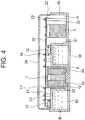
- FIG. 4 is a side sectional view illustrating a power converter according to a first embodiment of the present invention
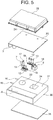
- FIG. 5 is an exploded perspective view of FIG. 4 .
- a case 30 made of aluminum, which is the first metal member, includes a bottom portion 32 above which the capacitors 3 are housed in the first space A and a projecting portion 31 which projects upward.
- An aperture of the projecting portion 31 of the case 30 is covered with a lid 25 made of aluminum, which is the second metal member.
- the second space B inside the projecting portion 31 is hermetically-sealed by the lid 35.
- a first concave portion 33 and a second concave portion 34 are formed so as to be separated away from each other.
- the reactor main body 7 is housed in the first concave portion 33.
- the transformer main body 8 including the core 40 and the coil 41 is housed in the second concave portion 34.
- the reactor main body 7 provided in the first concave portion 33 is positioned in the center of the first concave portion 33 by the resin holder 9, and is fixed with the insulating resin 10 filled in the first concave portion 33.
- the transformer main body 8 provided in the second concave portion 34 is positioned in the center of the second concave portion 34 by the resin holder (not shown), and is fixed with the insulating resin filled in the second concave portion 34.
- the plurality of semiconductor components 12 are fixed onto a surface of the projecting portion 31 of the case 30 by the fixation screws 13 through heat-radiating sheets (not shown).
- a wall (not shown) which connects the first concave portion 33 and the second concave portion 34 is formed.
- the U-like coolant passage 50 is formed in the second space B inside the projecting portion 31.
- the remaining configuration is the same as that of the power converter of the firstexample.
- the respective outer peripheries of the reactor main body 7 and the transformer main body 8 are surrounded by the second space B in which the ethylene glycol corresponding to the coolant flows. Therefore, a large heat-radiating area can be ensured for the reactor main body 7 and the transformer main body 8.
- the semiconductor components 12 are mounted on the plane 43 on the surface side, on which the first concave portion 33 and the second concave portion 34 are formed.
- the heat of the semiconductor components 12 is transferred to the ethylene glycol through the heat-radiating sheets and the plane 43 of the case 30 so as to be radiated therefrom. As a result, performance for radiating heat of the semiconductor components 12 is improved.
- the semiconductor components 12, the reactor main body 7, the transformer main body 8, and the capacitors 3 are provided in the spaces closed by the case 30 and the cover 25.
- the ethylene glycol in the second space B is closed by the lid 35 provided outside of the case 30. Therefore, even when the ethylene glycol in the second space B leaks out from a portion at which the case 30 and the lid 35 are connected, the ethylene glycol does not flow into the interior of the power converter.
- the ethylene glycol is prevented from adhering to the semiconductor components 12, the reactor main body 7, the transformer main body 8, the capacitors 3, and the like so as to avoid the occurrence of inconvenience such as a short-circuit, a conductor failure, and the like.
- the ethylene glycol is used as the coolant, the ethylene glycol is merely an example.
- the coolant for example, air may be used.
- the coolant passage 50 is a U-shaped path provided inside the second space B
- the coolant passage may be an I-shaped passage in which the coolant flows unidirectionally.
Landscapes
- Engineering & Computer Science (AREA)
- Microelectronics & Electronic Packaging (AREA)
- Power Engineering (AREA)
- Transportation (AREA)
- Mechanical Engineering (AREA)
- Physics & Mathematics (AREA)
- Thermal Sciences (AREA)
- Life Sciences & Earth Sciences (AREA)
- Sustainable Development (AREA)
- Sustainable Energy (AREA)
- Dc-Dc Converters (AREA)
- Inverter Devices (AREA)
Claims (7)
- Leistungswandler, umfassend:ein erstes Metallelement (4);ein zweites Metallelement (1), das mit dem ersten Metallelement (4) verbunden werden soll, um einen Raum (B) zu bilden, in dem ein Kühlmittel strömt; undeinen ersten elektrischen Heizelementhauptkörper, der in einem ersten konkaven Abschnitt (5, 33) untergebracht ist, der auf dem ersten Metallelement (4) ausgebildet ist, um in das Innere des Raumes (B) vorzustehen,einen zweiten elektrischen Heizelementhauptkörper, der in einem zweiten konkaven Abschnitt (6, 34) untergebracht ist, der auf dem ersten Metallelement (4) ausgebildet ist, um in das Innere des Raumes (B) vorzustehen,wobei die konkaven Abschnitte (5, 33, 6, 34) so ausgebildet sind, dass die konkaven Abschnitte (5, 33, 6, 34) voneinander getrennt sind,wobei die konkaven Abschnitte (5, 33, 6, 34) durch eine Wandung (2, 14) verbunden sind, die einen Zulauf und einen Rücklauf für das Kühlmittel trennt, um einen U-förmigen Kühlmittelkanal (50) in der Raum (B) auszubilden, undwobei das in eine mit dem Raum (B) in Verbindung stehende Einlassleitung (15) einströmende Kühlmittel durch den Zulauf und den Rücklauf strömt, um durch eine mit dem Raum (B) in Verbindung stehende Auslassleitung (16) auszuströmen.
- Leistungswandler nach Anspruch 1, bei dem das erste Metallelement (4) ein Halbleiterbauelement (12) zur Durchführung eines hochfrequenten Schaltvorgangs umfasst, wobei das Halbleiterbauelement (12) auf einer Ebene (43) montiert ist, an welcher der konkave Abschnitt (5, 33) ausgebildet ist.
- Leistungswandler nach Anspruch 2, bei dem sich distale Endabschnitte von Anschlüssen (17, 18, 19) des elektrischen Heizelementhauptkörpers und des Halbleiterbauelements (12) in einer Richtung senkrecht zur Ebene (43) erstrecken.
- Leistungswandler nach Anspruch 3, ferner umfassend eine Leiterplatte (20), die so vorgesehen ist, dass sie der Ebene (43) gegenüberliegt,
wobei die Anschlüsse (17, 18, 19) elektrisch mit der Leiterplatte (20) verbunden sind. - Leistungswandler nach einem der Ansprüche 1 bis 4, bei dem der elektrische Heizelementhauptkörper innerhalb des konkaven Abschnitts (5, 33) befestigt ist, wobei ein Isolierharz (10, 11) in den konkaven Abschnitt (5, 33) gefüllt ist.
- Leistungswandler nach einem der Ansprüche 1 bis 5, bei dem der elektrische Heizelementhauptkörper durch einen Harzhalter (9) zum Halten des elektrischen Heizelementhauptkörpers in einem Mittenbereich des konkaven Abschnitts (5, 33) angeordnet ist.
- Leistungswandler nach einem der vorhergehenden Ansprüche,
wobei der Leistungswandler einen fahrzeugseitigen Leistungswandler umfasst und
wobei ein Reaktorhauptkörper (7), welcher der elektrische Heizelementhauptkörper ist, in einem der konkaven Abschnitte (5, 33) untergebracht ist, während ein Transformatorhauptkörper (8), welcher der elektrische Heizelementhauptkörper ist, in einem anderen der konkaven Abschnitte (5, 33) untergebracht ist.
Applications Claiming Priority (1)
| Application Number | Priority Date | Filing Date | Title |
|---|---|---|---|
| PCT/JP2012/057034 WO2013140502A1 (ja) | 2012-03-19 | 2012-03-19 | 電力変換装置 |
Publications (3)
| Publication Number | Publication Date |
|---|---|
| EP2830073A1 EP2830073A1 (de) | 2015-01-28 |
| EP2830073A4 EP2830073A4 (de) | 2015-11-18 |
| EP2830073B1 true EP2830073B1 (de) | 2017-09-13 |
Family
ID=49221996
Family Applications (1)
| Application Number | Title | Priority Date | Filing Date |
|---|---|---|---|
| EP12871882.2A Active EP2830073B1 (de) | 2012-03-19 | 2012-03-19 | Stromrichter |
Country Status (4)
| Country | Link |
|---|---|
| US (1) | US9578790B2 (de) |
| EP (1) | EP2830073B1 (de) |
| JP (1) | JP5823020B2 (de) |
| WO (1) | WO2013140502A1 (de) |
Cited By (2)
| Publication number | Priority date | Publication date | Assignee | Title |
|---|---|---|---|---|
| EP4615182A1 (de) * | 2024-03-05 | 2025-09-10 | Huawei Digital Power Technologies Co., Ltd. | Leistungsmodul und ladevorrichtung |
| WO2026057232A1 (de) * | 2024-09-10 | 2026-03-19 | Robert Bosch Gmbh | Kühleranordnung |
Families Citing this family (42)
| Publication number | Priority date | Publication date | Assignee | Title |
|---|---|---|---|---|
| JP6045340B2 (ja) * | 2012-12-28 | 2016-12-14 | 日立オートモティブシステムズ株式会社 | Dc−dcコンバータ装置 |
| CN104684338B (zh) * | 2013-11-26 | 2018-01-30 | 台达电子企业管理(上海)有限公司 | 散热基座与电子装置 |
| CN104682722B (zh) * | 2013-11-26 | 2018-01-26 | 台达电子企业管理(上海)有限公司 | 电源转换装置及其组装方法 |
| CN104682457B (zh) | 2013-11-26 | 2017-08-29 | 台达电子企业管理(上海)有限公司 | 电子装置及汽车的充电装置 |
| DE102014217552A1 (de) * | 2014-09-03 | 2016-03-03 | Conti Temic Microelectronic Gmbh | Steuergerätevorrichtung für ein Kraftfahrzeug sowie Verfahren zum Herstellen einer solchen |
| KR101646375B1 (ko) * | 2014-11-05 | 2016-08-12 | 현대자동차주식회사 | 차량용 인덕터장치 |
| JP6459418B2 (ja) * | 2014-11-13 | 2019-01-30 | 富士電機株式会社 | 半導体装置およびその製造方法 |
| JP6426510B2 (ja) * | 2015-03-13 | 2018-11-21 | 矢崎総業株式会社 | 送電機器 |
| JP6488194B2 (ja) * | 2015-05-26 | 2019-03-20 | 株式会社日立製作所 | 電源装置 |
| JP6471050B2 (ja) * | 2015-06-17 | 2019-02-13 | 本田技研工業株式会社 | 電動車両 |
| JP2017055521A (ja) * | 2015-09-08 | 2017-03-16 | Tdk株式会社 | 電源装置 |
| CN106655710B (zh) | 2015-10-29 | 2019-02-22 | 台达电子企业管理(上海)有限公司 | 电源转换装置 |
| CN106655806B (zh) * | 2015-10-29 | 2019-02-26 | 台达电子企业管理(上海)有限公司 | 电源转换装置 |
| JP6656362B2 (ja) * | 2016-04-25 | 2020-03-04 | 三菱電機株式会社 | 電力変換装置 |
| WO2017187479A1 (ja) * | 2016-04-25 | 2017-11-02 | 三菱電機株式会社 | 車載充電器およびその製造方法 |
| US10888035B2 (en) * | 2016-09-20 | 2021-01-05 | Mitsubishi Electric Corporation | Power conversion device |
| US10893610B2 (en) | 2017-04-03 | 2021-01-12 | Mitsubishi Electric Cornoration | Switching device driving unit |
| CN108336892B (zh) * | 2017-05-25 | 2021-11-16 | 泰达电子股份有限公司 | 电源模块及其组装结构与组装方法 |
| JP2019033624A (ja) * | 2017-08-09 | 2019-02-28 | 株式会社デンソー | 電力変換装置 |
| CN108076617B (zh) * | 2018-01-04 | 2021-02-02 | 深圳威迈斯新能源股份有限公司 | 用于车载充电机或电压变换器的散热结构 |
| CN112042092B (zh) * | 2018-04-25 | 2024-03-01 | 松下知识产权经营株式会社 | 电源装置 |
| JP6509414B1 (ja) | 2018-07-30 | 2019-05-08 | 三菱電機株式会社 | 電力変換装置 |
| JP7073969B2 (ja) * | 2018-08-01 | 2022-05-24 | 株式会社デンソー | 電力変換装置 |
| JP6541859B1 (ja) | 2018-11-01 | 2019-07-10 | 三菱電機株式会社 | 電力変換装置 |
| CN113228482B (zh) * | 2018-12-26 | 2024-03-08 | 松下知识产权经营株式会社 | 电力转换装置 |
| JP7620567B2 (ja) * | 2019-04-19 | 2025-01-23 | メタ システム エス.ピー.エー. | 電気車両またはハイブリッド車両の電子電力変換装置 |
| EP3770005B8 (de) | 2019-07-25 | 2023-12-06 | ABB E-mobility B.V. | Elektrofahrzeugladesystem zum laden eines elektrofahrzeugs |
| US11670443B2 (en) * | 2019-11-18 | 2023-06-06 | Ford Global Technologies, Llc | Liquid cooled inductor via nozzle spray |
| JP7304540B2 (ja) * | 2019-12-12 | 2023-07-07 | パナソニックIpマネジメント株式会社 | 電力変換装置、及び電力変換装置の製造方法 |
| JP7262012B2 (ja) * | 2020-06-10 | 2023-04-21 | パナソニックIpマネジメント株式会社 | 車載充電器およびインバータ |
| CN113923963B (zh) | 2020-07-09 | 2023-03-24 | 比亚迪股份有限公司 | 车载电源装置及具有其的车辆 |
| KR102385919B1 (ko) * | 2020-08-11 | 2022-04-18 | 센서나인(주) | 고전압 트랜스포머 |
| KR20220099022A (ko) * | 2021-01-05 | 2022-07-12 | 엘지이노텍 주식회사 | 컨버터 |
| JP7366077B2 (ja) * | 2021-03-09 | 2023-10-20 | 三菱電機株式会社 | 電力変換装置 |
| CN113079678A (zh) * | 2021-03-29 | 2021-07-06 | 阳光电源股份有限公司 | 液冷散热装置及功率模块 |
| KR20220145653A (ko) * | 2021-04-22 | 2022-10-31 | 현대자동차주식회사 | 전력 변환 장치 |
| AT525115B1 (de) * | 2021-06-10 | 2025-05-15 | Avl List Gmbh | Elektronikvorrichtung für eine Leistungselektronik einer elektrischen Antriebsvorrichtung eines Fahrzeugs |
| CN116437624A (zh) | 2022-01-11 | 2023-07-14 | 开利公司 | 机械封壳 |
| JP7180805B1 (ja) * | 2022-03-08 | 2022-11-30 | 富士電機株式会社 | 電力変換装置および直流直流コンバータ装置 |
| JP7439155B2 (ja) * | 2022-03-25 | 2024-02-27 | 本田技研工業株式会社 | 電力変換装置 |
| FR3157055B1 (fr) * | 2023-12-13 | 2026-02-13 | Sogefi Air & Cooling | Module électronique de puissance, son procédé de fabrication et véhicule comportant un tel module |
| CN120980829A (zh) * | 2024-05-16 | 2025-11-18 | 法雷奥新能源汽车德国有限责任公司 | 电气装置、电驱动系统和车辆 |
Family Cites Families (34)
| Publication number | Priority date | Publication date | Assignee | Title |
|---|---|---|---|---|
| US5159529A (en) * | 1991-05-15 | 1992-10-27 | International Business Machines Corporation | Composite liquid cooled plate for electronic equipment |
| JPH08149621A (ja) * | 1994-11-18 | 1996-06-07 | Sansha Electric Mfg Co Ltd | 密閉型電源冷却装置 |
| JP3066726B2 (ja) | 1995-11-08 | 2000-07-17 | 富士通電装株式会社 | 半導体装置の取付け構造 |
| JP4218184B2 (ja) | 2000-05-19 | 2009-02-04 | 株式会社デンソー | 半導体装置の実装構造 |
| JP2002050527A (ja) | 2000-07-31 | 2002-02-15 | Honda Motor Co Ltd | 冷却装置付きリアクトル |
| JP2002198477A (ja) | 2000-12-25 | 2002-07-12 | Toyota Motor Corp | 半導体装置 |
| JP3946018B2 (ja) * | 2001-09-18 | 2007-07-18 | 株式会社日立製作所 | 液冷却式回路装置 |
| US6865080B2 (en) * | 2002-01-16 | 2005-03-08 | Rockwell Automation Technologies, Inc. | Compact fluid cooled power converter supporting multiple circuit boards |
| JP4003719B2 (ja) | 2003-08-22 | 2007-11-07 | 株式会社デンソー | 電力変換装置 |
| JP4154325B2 (ja) * | 2003-12-19 | 2008-09-24 | 株式会社日立産機システム | 電気回路モジュール |
| JP2005229033A (ja) * | 2004-02-16 | 2005-08-25 | Hitachi Ltd | 液冷システムおよびそれを備えた電子機器 |
| US20080117602A1 (en) | 2006-11-20 | 2008-05-22 | Korich Mark D | Power inverter having liquid cooled capacitor and low inductance bus structure |
| US7710723B2 (en) * | 2007-07-17 | 2010-05-04 | Gm Global Technology Operations, Inc. | Vehicle inverter assembly with cooling channels |
| JP4819071B2 (ja) * | 2008-02-06 | 2011-11-16 | 本田技研工業株式会社 | 電気車両及び車両用dc/dcコンバータの冷却方法 |
| JP4580997B2 (ja) * | 2008-03-11 | 2010-11-17 | 日立オートモティブシステムズ株式会社 | 電力変換装置 |
| JP5146287B2 (ja) * | 2008-12-02 | 2013-02-20 | 株式会社デンソー | リアクトル |
| US8169780B2 (en) * | 2009-06-18 | 2012-05-01 | Honda Motor Co., Ltd. | Power conversion device |
| US8064198B2 (en) * | 2009-06-29 | 2011-11-22 | Honda Motor Co., Ltd. | Cooling device for semiconductor element module and magnetic part |
| JP5099086B2 (ja) * | 2009-07-28 | 2012-12-12 | 株式会社デンソー | 電源装置 |
| US8570132B2 (en) | 2009-10-27 | 2013-10-29 | GM Global Technology Operations LLC | Power electronics assembly with multi-sided inductor cooling |
| JP2011151193A (ja) * | 2010-01-21 | 2011-08-04 | Toyota Motor Corp | 冷却器 |
| JP5422466B2 (ja) * | 2010-04-01 | 2014-02-19 | 日立オートモティブシステムズ株式会社 | 電力変換装置 |
| JP5618595B2 (ja) * | 2010-04-01 | 2014-11-05 | 日立オートモティブシステムズ株式会社 | パワーモジュール、およびパワーモジュールを備えた電力変換装置 |
| JP2011228508A (ja) * | 2010-04-21 | 2011-11-10 | Toyota Motor Corp | パワーモジュール |
| JP5380376B2 (ja) * | 2010-06-21 | 2014-01-08 | 日立オートモティブシステムズ株式会社 | パワー半導体装置 |
| JP5563383B2 (ja) * | 2010-06-21 | 2014-07-30 | 日立オートモティブシステムズ株式会社 | 電力変換装置 |
| DE102010043446B3 (de) * | 2010-11-05 | 2012-01-12 | Semikron Elektronik Gmbh & Co. Kg | Leistungshalbleitersystem |
| JP2012174856A (ja) * | 2011-02-21 | 2012-09-10 | Hitachi Cable Ltd | ヒートシンク及びその製造方法 |
| JP5506741B2 (ja) * | 2011-06-02 | 2014-05-28 | 日立オートモティブシステムズ株式会社 | 電力変換装置 |
| JP5502805B2 (ja) * | 2011-06-08 | 2014-05-28 | 日立オートモティブシステムズ株式会社 | パワーモジュールおよびそれを用いた電力変換装置 |
| WO2013080317A1 (ja) * | 2011-11-30 | 2013-06-06 | 三菱電機株式会社 | 半導体装置、及び車載用電力変換装置 |
| JP5783212B2 (ja) * | 2013-09-06 | 2015-09-24 | Tdk株式会社 | 電源装置 |
| CN104684338B (zh) * | 2013-11-26 | 2018-01-30 | 台达电子企业管理(上海)有限公司 | 散热基座与电子装置 |
| US9362040B2 (en) * | 2014-05-15 | 2016-06-07 | Lear Corporation | Coldplate with integrated electrical components for cooling thereof |
-
2012
- 2012-03-19 EP EP12871882.2A patent/EP2830073B1/de active Active
- 2012-03-19 WO PCT/JP2012/057034 patent/WO2013140502A1/ja not_active Ceased
- 2012-03-19 JP JP2014505833A patent/JP5823020B2/ja active Active
- 2012-03-19 US US14/372,664 patent/US9578790B2/en active Active
Non-Patent Citations (1)
| Title |
|---|
| None * |
Cited By (2)
| Publication number | Priority date | Publication date | Assignee | Title |
|---|---|---|---|---|
| EP4615182A1 (de) * | 2024-03-05 | 2025-09-10 | Huawei Digital Power Technologies Co., Ltd. | Leistungsmodul und ladevorrichtung |
| WO2026057232A1 (de) * | 2024-09-10 | 2026-03-19 | Robert Bosch Gmbh | Kühleranordnung |
Also Published As
| Publication number | Publication date |
|---|---|
| JPWO2013140502A1 (ja) | 2015-08-03 |
| EP2830073A4 (de) | 2015-11-18 |
| WO2013140502A1 (ja) | 2013-09-26 |
| JP5823020B2 (ja) | 2015-11-25 |
| CN104205260A (zh) | 2014-12-10 |
| US9578790B2 (en) | 2017-02-21 |
| EP2830073A1 (de) | 2015-01-28 |
| US20150208556A1 (en) | 2015-07-23 |
Similar Documents
| Publication | Publication Date | Title |
|---|---|---|
| EP2830073B1 (de) | Stromrichter | |
| JP6104347B1 (ja) | 電力変換装置 | |
| US9750147B2 (en) | Power converter | |
| US10128770B2 (en) | Converter and electric power conversion apparatus | |
| US9608528B2 (en) | DC-DC converter apparatus | |
| JP5535292B2 (ja) | 電力変換装置 | |
| US9445525B2 (en) | Power supply device | |
| US20150163961A1 (en) | Power Conversion Apparatus | |
| US11588413B2 (en) | Power conversion device | |
| EP3057216B1 (de) | Gleichspannungswandler | |
| JP7527446B2 (ja) | 電力変換装置 | |
| US20250007365A1 (en) | Integrated motor controller, electric assembly, and vehicle | |
| JP6180857B2 (ja) | 電力変換装置 | |
| KR102458738B1 (ko) | 커패시터 직접냉각방식의 인버터 | |
| JP2015023720A (ja) | 電力変換装置 | |
| US20140284028A1 (en) | Cooler | |
| CN113286498A (zh) | 集成散热模组、车载充电机及电动汽车 | |
| JP2016063595A (ja) | 電力変換装置 | |
| CN113068377A (zh) | 一种发热器件散热结构、散热组件及电气设备 | |
| CN104205260B (zh) | 功率转换装置 | |
| EP4615183A1 (de) | Leistungsmodul und ladevorrichtung | |
| CN215342210U (zh) | 变压器组件及直流电源模块 | |
| WO2024106475A1 (ja) | 電源モジュール | |
| JP2025079243A (ja) | 電力変換装置 | |
| JP2016059192A (ja) | 電力変換装置 |
Legal Events
| Date | Code | Title | Description |
|---|---|---|---|
| PUAI | Public reference made under article 153(3) epc to a published international application that has entered the european phase |
Free format text: ORIGINAL CODE: 0009012 |
|
| 17P | Request for examination filed |
Effective date: 20140717 |
|
| AK | Designated contracting states |
Kind code of ref document: A1 Designated state(s): AL AT BE BG CH CY CZ DE DK EE ES FI FR GB GR HR HU IE IS IT LI LT LU LV MC MK MT NL NO PL PT RO RS SE SI SK SM TR |
|
| AX | Request for extension of the european patent |
Extension state: BA ME |
|
| DAX | Request for extension of the european patent (deleted) | ||
| RA4 | Supplementary search report drawn up and despatched (corrected) |
Effective date: 20151016 |
|
| RIC1 | Information provided on ipc code assigned before grant |
Ipc: H01F 30/00 20060101AFI20151012BHEP Ipc: H01F 27/10 20060101ALN20151012BHEP Ipc: H05K 7/20 20060101ALN20151012BHEP Ipc: H01F 27/02 20060101ALN20151012BHEP Ipc: H01F 37/00 20060101ALI20151012BHEP Ipc: H02M 7/48 20070101ALI20151012BHEP |
|
| 17Q | First examination report despatched |
Effective date: 20161018 |
|
| GRAP | Despatch of communication of intention to grant a patent |
Free format text: ORIGINAL CODE: EPIDOSNIGR1 |
|
| RIC1 | Information provided on ipc code assigned before grant |
Ipc: H05K 7/20 20060101ALN20170322BHEP Ipc: H01F 30/00 20060101AFI20170322BHEP Ipc: H01F 27/02 20060101ALN20170322BHEP Ipc: H01F 37/00 20060101ALI20170322BHEP Ipc: H02M 7/48 20070101ALI20170322BHEP Ipc: H01F 27/10 20060101ALN20170322BHEP |
|
| INTG | Intention to grant announced |
Effective date: 20170406 |
|
| GRAS | Grant fee paid |
Free format text: ORIGINAL CODE: EPIDOSNIGR3 |
|
| GRAA | (expected) grant |
Free format text: ORIGINAL CODE: 0009210 |
|
| AK | Designated contracting states |
Kind code of ref document: B1 Designated state(s): AL AT BE BG CH CY CZ DE DK EE ES FI FR GB GR HR HU IE IS IT LI LT LU LV MC MK MT NL NO PL PT RO RS SE SI SK SM TR |
|
| REG | Reference to a national code |
Ref country code: GB Ref legal event code: FG4D |
|
| REG | Reference to a national code |
Ref country code: CH Ref legal event code: EP |
|
| REG | Reference to a national code |
Ref country code: IE Ref legal event code: FG4D |
|
| REG | Reference to a national code |
Ref country code: AT Ref legal event code: REF Ref document number: 928895 Country of ref document: AT Kind code of ref document: T Effective date: 20171015 |
|
| REG | Reference to a national code |
Ref country code: DE Ref legal event code: R096 Ref document number: 602012037453 Country of ref document: DE |
|
| REG | Reference to a national code |
Ref country code: NL Ref legal event code: MP Effective date: 20170913 |
|
| REG | Reference to a national code |
Ref country code: LT Ref legal event code: MG4D |
|
| PG25 | Lapsed in a contracting state [announced via postgrant information from national office to epo] |
Ref country code: LT Free format text: LAPSE BECAUSE OF FAILURE TO SUBMIT A TRANSLATION OF THE DESCRIPTION OR TO PAY THE FEE WITHIN THE PRESCRIBED TIME-LIMIT Effective date: 20170913 Ref country code: FI Free format text: LAPSE BECAUSE OF FAILURE TO SUBMIT A TRANSLATION OF THE DESCRIPTION OR TO PAY THE FEE WITHIN THE PRESCRIBED TIME-LIMIT Effective date: 20170913 Ref country code: HR Free format text: LAPSE BECAUSE OF FAILURE TO SUBMIT A TRANSLATION OF THE DESCRIPTION OR TO PAY THE FEE WITHIN THE PRESCRIBED TIME-LIMIT Effective date: 20170913 Ref country code: NO Free format text: LAPSE BECAUSE OF FAILURE TO SUBMIT A TRANSLATION OF THE DESCRIPTION OR TO PAY THE FEE WITHIN THE PRESCRIBED TIME-LIMIT Effective date: 20171213 Ref country code: SE Free format text: LAPSE BECAUSE OF FAILURE TO SUBMIT A TRANSLATION OF THE DESCRIPTION OR TO PAY THE FEE WITHIN THE PRESCRIBED TIME-LIMIT Effective date: 20170913 |
|
| REG | Reference to a national code |
Ref country code: AT Ref legal event code: MK05 Ref document number: 928895 Country of ref document: AT Kind code of ref document: T Effective date: 20170913 |
|
| REG | Reference to a national code |
Ref country code: FR Ref legal event code: PLFP Year of fee payment: 7 |
|
| PG25 | Lapsed in a contracting state [announced via postgrant information from national office to epo] |
Ref country code: ES Free format text: LAPSE BECAUSE OF FAILURE TO SUBMIT A TRANSLATION OF THE DESCRIPTION OR TO PAY THE FEE WITHIN THE PRESCRIBED TIME-LIMIT Effective date: 20170913 Ref country code: BG Free format text: LAPSE BECAUSE OF FAILURE TO SUBMIT A TRANSLATION OF THE DESCRIPTION OR TO PAY THE FEE WITHIN THE PRESCRIBED TIME-LIMIT Effective date: 20171213 Ref country code: LV Free format text: LAPSE BECAUSE OF FAILURE TO SUBMIT A TRANSLATION OF THE DESCRIPTION OR TO PAY THE FEE WITHIN THE PRESCRIBED TIME-LIMIT Effective date: 20170913 Ref country code: RS Free format text: LAPSE BECAUSE OF FAILURE TO SUBMIT A TRANSLATION OF THE DESCRIPTION OR TO PAY THE FEE WITHIN THE PRESCRIBED TIME-LIMIT Effective date: 20170913 Ref country code: GR Free format text: LAPSE BECAUSE OF FAILURE TO SUBMIT A TRANSLATION OF THE DESCRIPTION OR TO PAY THE FEE WITHIN THE PRESCRIBED TIME-LIMIT Effective date: 20171214 |
|
| PG25 | Lapsed in a contracting state [announced via postgrant information from national office to epo] |
Ref country code: NL Free format text: LAPSE BECAUSE OF FAILURE TO SUBMIT A TRANSLATION OF THE DESCRIPTION OR TO PAY THE FEE WITHIN THE PRESCRIBED TIME-LIMIT Effective date: 20170913 |
|
| PG25 | Lapsed in a contracting state [announced via postgrant information from national office to epo] |
Ref country code: PL Free format text: LAPSE BECAUSE OF FAILURE TO SUBMIT A TRANSLATION OF THE DESCRIPTION OR TO PAY THE FEE WITHIN THE PRESCRIBED TIME-LIMIT Effective date: 20170913 Ref country code: CZ Free format text: LAPSE BECAUSE OF FAILURE TO SUBMIT A TRANSLATION OF THE DESCRIPTION OR TO PAY THE FEE WITHIN THE PRESCRIBED TIME-LIMIT Effective date: 20170913 Ref country code: RO Free format text: LAPSE BECAUSE OF FAILURE TO SUBMIT A TRANSLATION OF THE DESCRIPTION OR TO PAY THE FEE WITHIN THE PRESCRIBED TIME-LIMIT Effective date: 20170913 |
|
| PG25 | Lapsed in a contracting state [announced via postgrant information from national office to epo] |
Ref country code: IT Free format text: LAPSE BECAUSE OF FAILURE TO SUBMIT A TRANSLATION OF THE DESCRIPTION OR TO PAY THE FEE WITHIN THE PRESCRIBED TIME-LIMIT Effective date: 20170913 Ref country code: SM Free format text: LAPSE BECAUSE OF FAILURE TO SUBMIT A TRANSLATION OF THE DESCRIPTION OR TO PAY THE FEE WITHIN THE PRESCRIBED TIME-LIMIT Effective date: 20170913 Ref country code: AT Free format text: LAPSE BECAUSE OF FAILURE TO SUBMIT A TRANSLATION OF THE DESCRIPTION OR TO PAY THE FEE WITHIN THE PRESCRIBED TIME-LIMIT Effective date: 20170913 Ref country code: EE Free format text: LAPSE BECAUSE OF FAILURE TO SUBMIT A TRANSLATION OF THE DESCRIPTION OR TO PAY THE FEE WITHIN THE PRESCRIBED TIME-LIMIT Effective date: 20170913 Ref country code: SK Free format text: LAPSE BECAUSE OF FAILURE TO SUBMIT A TRANSLATION OF THE DESCRIPTION OR TO PAY THE FEE WITHIN THE PRESCRIBED TIME-LIMIT Effective date: 20170913 Ref country code: IS Free format text: LAPSE BECAUSE OF FAILURE TO SUBMIT A TRANSLATION OF THE DESCRIPTION OR TO PAY THE FEE WITHIN THE PRESCRIBED TIME-LIMIT Effective date: 20180113 |
|
| REG | Reference to a national code |
Ref country code: DE Ref legal event code: R097 Ref document number: 602012037453 Country of ref document: DE |
|
| PLBE | No opposition filed within time limit |
Free format text: ORIGINAL CODE: 0009261 |
|
| STAA | Information on the status of an ep patent application or granted ep patent |
Free format text: STATUS: NO OPPOSITION FILED WITHIN TIME LIMIT |
|
| PG25 | Lapsed in a contracting state [announced via postgrant information from national office to epo] |
Ref country code: DK Free format text: LAPSE BECAUSE OF FAILURE TO SUBMIT A TRANSLATION OF THE DESCRIPTION OR TO PAY THE FEE WITHIN THE PRESCRIBED TIME-LIMIT Effective date: 20170913 |
|
| 26N | No opposition filed |
Effective date: 20180614 |
|
| REG | Reference to a national code |
Ref country code: CH Ref legal event code: PL |
|
| GBPC | Gb: european patent ceased through non-payment of renewal fee |
Effective date: 20180319 |
|
| PG25 | Lapsed in a contracting state [announced via postgrant information from national office to epo] |
Ref country code: SI Free format text: LAPSE BECAUSE OF FAILURE TO SUBMIT A TRANSLATION OF THE DESCRIPTION OR TO PAY THE FEE WITHIN THE PRESCRIBED TIME-LIMIT Effective date: 20170913 Ref country code: MC Free format text: LAPSE BECAUSE OF FAILURE TO SUBMIT A TRANSLATION OF THE DESCRIPTION OR TO PAY THE FEE WITHIN THE PRESCRIBED TIME-LIMIT Effective date: 20170913 |
|
| REG | Reference to a national code |
Ref country code: BE Ref legal event code: MM Effective date: 20180331 |
|
| REG | Reference to a national code |
Ref country code: IE Ref legal event code: MM4A |
|
| PG25 | Lapsed in a contracting state [announced via postgrant information from national office to epo] |
Ref country code: LU Free format text: LAPSE BECAUSE OF NON-PAYMENT OF DUE FEES Effective date: 20180319 |
|
| PG25 | Lapsed in a contracting state [announced via postgrant information from national office to epo] |
Ref country code: IE Free format text: LAPSE BECAUSE OF NON-PAYMENT OF DUE FEES Effective date: 20180319 |
|
| PG25 | Lapsed in a contracting state [announced via postgrant information from national office to epo] |
Ref country code: BE Free format text: LAPSE BECAUSE OF NON-PAYMENT OF DUE FEES Effective date: 20180331 Ref country code: LI Free format text: LAPSE BECAUSE OF NON-PAYMENT OF DUE FEES Effective date: 20180331 Ref country code: CH Free format text: LAPSE BECAUSE OF NON-PAYMENT OF DUE FEES Effective date: 20180331 Ref country code: GB Free format text: LAPSE BECAUSE OF NON-PAYMENT OF DUE FEES Effective date: 20180319 |
|
| PG25 | Lapsed in a contracting state [announced via postgrant information from national office to epo] |
Ref country code: MT Free format text: LAPSE BECAUSE OF NON-PAYMENT OF DUE FEES Effective date: 20180319 |
|
| PG25 | Lapsed in a contracting state [announced via postgrant information from national office to epo] |
Ref country code: TR Free format text: LAPSE BECAUSE OF FAILURE TO SUBMIT A TRANSLATION OF THE DESCRIPTION OR TO PAY THE FEE WITHIN THE PRESCRIBED TIME-LIMIT Effective date: 20170913 |
|
| PG25 | Lapsed in a contracting state [announced via postgrant information from national office to epo] |
Ref country code: PT Free format text: LAPSE BECAUSE OF FAILURE TO SUBMIT A TRANSLATION OF THE DESCRIPTION OR TO PAY THE FEE WITHIN THE PRESCRIBED TIME-LIMIT Effective date: 20170913 Ref country code: HU Free format text: LAPSE BECAUSE OF FAILURE TO SUBMIT A TRANSLATION OF THE DESCRIPTION OR TO PAY THE FEE WITHIN THE PRESCRIBED TIME-LIMIT; INVALID AB INITIO Effective date: 20120319 |
|
| PG25 | Lapsed in a contracting state [announced via postgrant information from national office to epo] |
Ref country code: MK Free format text: LAPSE BECAUSE OF NON-PAYMENT OF DUE FEES Effective date: 20170913 Ref country code: CY Free format text: LAPSE BECAUSE OF FAILURE TO SUBMIT A TRANSLATION OF THE DESCRIPTION OR TO PAY THE FEE WITHIN THE PRESCRIBED TIME-LIMIT Effective date: 20170913 |
|
| PG25 | Lapsed in a contracting state [announced via postgrant information from national office to epo] |
Ref country code: AL Free format text: LAPSE BECAUSE OF FAILURE TO SUBMIT A TRANSLATION OF THE DESCRIPTION OR TO PAY THE FEE WITHIN THE PRESCRIBED TIME-LIMIT Effective date: 20170913 |
|
| P01 | Opt-out of the competence of the unified patent court (upc) registered |
Effective date: 20230512 |
|
| REG | Reference to a national code |
Ref country code: DE Ref legal event code: R084 Ref document number: 602012037453 Country of ref document: DE |
|
| PGFP | Annual fee paid to national office [announced via postgrant information from national office to epo] |
Ref country code: DE Payment date: 20260128 Year of fee payment: 15 |
|
| PGFP | Annual fee paid to national office [announced via postgrant information from national office to epo] |
Ref country code: FR Payment date: 20260209 Year of fee payment: 15 |