EP2830236B1 - Zeitduplex-kommunikationsverfahren, system und vorrichtung - Google Patents
Zeitduplex-kommunikationsverfahren, system und vorrichtung Download PDFInfo
- Publication number
- EP2830236B1 EP2830236B1 EP13764633.7A EP13764633A EP2830236B1 EP 2830236 B1 EP2830236 B1 EP 2830236B1 EP 13764633 A EP13764633 A EP 13764633A EP 2830236 B1 EP2830236 B1 EP 2830236B1
- Authority
- EP
- European Patent Office
- Prior art keywords
- sub
- frame
- carry
- feedback information
- uplink
- Prior art date
- Legal status (The legal status is an assumption and is not a legal conclusion. Google has not performed a legal analysis and makes no representation as to the accuracy of the status listed.)
- Active
Links
Images



Classifications
-
- H—ELECTRICITY
- H04—ELECTRIC COMMUNICATION TECHNIQUE
- H04W—WIRELESS COMMUNICATION NETWORKS
- H04W72/00—Local resource management
- H04W72/20—Control channels or signalling for resource management
- H04W72/23—Control channels or signalling for resource management in the downlink direction of a wireless link, i.e. towards a terminal
-
- H—ELECTRICITY
- H04—ELECTRIC COMMUNICATION TECHNIQUE
- H04B—TRANSMISSION
- H04B7/00—Radio transmission systems, i.e. using radiation field
- H04B7/24—Radio transmission systems, i.e. using radiation field for communication between two or more posts
- H04B7/26—Radio transmission systems, i.e. using radiation field for communication between two or more posts at least one of which is mobile
- H04B7/2643—Radio transmission systems, i.e. using radiation field for communication between two or more posts at least one of which is mobile using time-division multiple access [TDMA]
-
- H—ELECTRICITY
- H04—ELECTRIC COMMUNICATION TECHNIQUE
- H04B—TRANSMISSION
- H04B7/00—Radio transmission systems, i.e. using radiation field
- H04B7/24—Radio transmission systems, i.e. using radiation field for communication between two or more posts
- H04B7/26—Radio transmission systems, i.e. using radiation field for communication between two or more posts at least one of which is mobile
- H04B7/2612—Arrangements for wireless medium access control, e.g. by allocating physical layer transmission capacity
-
- H—ELECTRICITY
- H04—ELECTRIC COMMUNICATION TECHNIQUE
- H04L—TRANSMISSION OF DIGITAL INFORMATION, e.g. TELEGRAPHIC COMMUNICATION
- H04L5/00—Arrangements affording multiple use of the transmission path
- H04L5/14—Two-way operation using the same type of signal, i.e. duplex
Definitions
- the present invention relates to the field of wireless communications and particularly to a time division duplex communication method, system and apparatus.
- the Time Division Duplex (TDD) mode which is one of two general duplex systems refers to the use of the same operating band in the uplink and the downlink, transmission of uplink and downlink signals over different time intervals and the presence of a Guard Period (GP) between the uplink and the downlink.
- TDD Time Division Duplex
- GP Guard Period
- a radio frame has a length of 10ms and includes two types of sub-frames which are special sub-frames and normal sub-frames, totaling to 10 sub-frames, each of which is 1ms.
- LTE Long Term Evolution
- the special sub-frames include three sub-frames which are a Downlink Pilot Slot (DwPTS) for transmission of a Primary Synchronization Signal (PSS), a Physical Downlink Control Channel (PDCCH), a Physical Hybrid Automatic Repeat Request (HARQ) Indication Channel (PHICH), a Physical Control Format Indication Channel (PCFICH), a Physical Downlink Shared Channel (PDSCH), etc.; a GP for a guard period between the downlink and the uplink; and an Uplink Pilot Slot (UpPTS) for transmission of a Sounding Reference Signal (SRS), a Physical Random Access Channel (PRACH), etc.
- the normal sub-frames include uplink sub-frames and downlink sub-frames for transmission of an uplink/downlink control channel, service data, etc.
- the sub-frame 0 and the sub-frame 5 as well as the DwPTS sub-frame among the special sub-frames are constantly used for downlink transmission, the sub-frame 2 and the UpPTS sub-frame among the special sub-frames are constantly used for uplink transmission, and the other sub-frames can be configured for uplink transmission or downlink transmission as needed.
- Uplink/downlink signals are transmitted in different sub-frames over the same frequency resources in the uplink and the downlink in a TDD system.
- TDD systems including a 3G Time Division-Synchronous Code Division Multiple Access (TD-SCDMA) system and a 4G TD-LTE system
- uplink and downlink sub-frames are allocated statically or semi-statically, and a common practice is to plan a network by determining the proportion of uplink to downlink sub-frames according to the type of a cell and a rough proportion of traffic and keeping the proportion unchanged. This is a simple practice in the context of large coverage by a macro cell.
- WO2012165782A2 discloses "A data transmission method and apparatus is provided for transmitting UL grant or ACK/NACK at flexible subframes in a Time Division Duplex (TDD) system.
- the data transmission method of a base station according to the present invention includes configuring subframes irrelevant to Hybrid Automatic Repeat reQuest (HARQ) process as flexible subframes; scheduling uplink transmission at the flexible subframes with uplink grant; receiving uplink data transmitted by a terminal at the flexible subframes as scheduled; and transmitting, when decoding the uplink data fails, HARQ acknowledgement/negative acknowledgement (ACK/NACK) or uplink grant to request retransmission of the uplink data.;
- the data transmission method of the present invention is capable of utilizing flexible subframes for uplink transmission without influencing the uplink HARQ process associated with the downlink subframes configured as flexible subframes".
- US 2011096701A1 discloses "A transmission method for a wireless relay system and a relay station using the same are provided.
- the wireless relay system includes at least a base station (eNB), at least a relay node (RN) and at least a user equipment (UE).
- the eNB is facilitated by the RN to provide a data transmission service to the UE.
- WO2010049587A1 discloses "Systems and methods for enabling the dynamic allocation of certain sub frames as downlink or uplink resources in a time division duplexed over the air communications system.
- a base station or eNB may allocate certain subframes within a repeating radio frame of a TDD configuration as eitehr DL or UL subframes for communicating to user equipment or UE devices to increase efficient use of system resources based on the data to be transmitted.
- Methods for determining the capabilities of a selected UE and based on the determining step, dynamically allocating certain subframes are disclosed. The methods and systems are compatible with user equipment that does not support the dynamic allocation of subframes".
- CN102231662A discloses "The invention discloses a data transmission method, which is used for realizing data transmission during dynamic allocation of upstream and downstream subframes.
- a dynamic subframe system is composed of four kinds of subframes.
- a first kind of subframe is only used as a subframe for downstream transmission;
- a second subframe is only used as a subframe for upstream transmission;
- a third kind of subframe can be dynamically configured to be as a subframe for upstream or downstream transmission, but the third kind of subframe can not be used for upstream and downstream transmission simultaneously;
- a fourth kind of subframe is a special time slot and comprises a DwPTS, a GP and an UpPTS.
- a processing method of upstream transmission at a sending terminal comprises the following steps that: the sending terminal only receives a UL grant in a DwPTS of a the first kind of substream or a fourth kind of substream; and the sending terminal sends data in the second kind of substream or the third kind of substream.
- the invention also discloses a processing method of upstream transmission at a receiving terminal and an apparatus for realizing the method.
- US2011085478 A1 discloses "A relay transmission method and apparatus are provided.
- the method includes: configuring a subframe of a Time Division Duplex (TDD) relay frame for a subframe of relay link (S201), where the configuring the subframe of the TDD relay frame for the subframe of relay link includes: configuring a downlink (DL) subframe of the TDD relay frame for a DL subframe of relay link, and / or configuring the DL subframe of the TDD relay frame for an uplink (UL) subframe of relay link, and / or configuring a UL subframe of the TDD relay frame for the UL subframe of relay link; and performing relay transmission according to the subframe of relay link (S202).
- DL downlink
- UL uplink
- Embodiments of the invention provide a time division duplex communication method, system and apparatus so as to address the problem in the prior art of the absence so far of an uplink and downlink HARQ timing relationship for a scheme for dynamic allocation of uplink and downlink sub-frames.
- An embodiment of the invention provides a method of time division duplex reception of downlink data, the method including: a user equipment receiving PDSCH data from the network side in an mth sub-frame, sub-frame m, in a radio frame, wherein the sub-frame 0 and the sub-frame 5 in the radio frame are fixed downlink sub-frames, the sub-frame 2 is a fixed uplink sub-frame, the sub-frame 1 is a special sub-frame, the sub-frame 6 is a special sub-frame or a downlink sub-frame, the remaining sub-frames are flexible sub-frames which are with a variable transmission direction, and the sub-frame n is a downlink sub-frame to carry the PDSCH data; and the user equipment determining a sub-frame to carry feedback information corresponding to the PDSCH data according to a timing relationship between the feedback information and transmission of the PDSCH data and transmitting the feedback information in the determined sub-frame; wherein the timing relationship between the feedback information and transmission of the PDSCH data comprises:
- An embodiment of the invention provides a method of time division duplex reception of uplink data, the method including:
- the user equipment receives the indication information from the network side in the sub-frame n in the radio frame and transmits the PUSCH data in at least one uplink sub-frame after the sub-frame n upon determining from the indication information that the PUSCH data needs to be transmitted to the network side; and in the downlink HARQ timing relationship according to the embodiments of the invention, the user equipment receives the PDSCH data from the network side in the sub-frame m in the radio frame, determines the sub-frame to carry the feedback information corresponding to the PDSCH data according to the timing relationship between the feedback information and the PDSCH data, and transmits the feedback information in the determined sub-frame, thus addressing the problem in the prior art of the absence of an HARQ timing relationship for dynamic uplink and downlink configuration and enabling the dynamic TDD system to transmit uplink and downlink data.
- a user equipment receives indication information from the network side in the sub-frame n in a radio frame and transmits PUSCH data in at least one uplink sub-frame after the sub-frame n upon determining from the indication information that the PUSCH data needs to be transmitted to the network side; and the network side according to the embodiments of the invention determines the sub-frame n to carry the indication information in the radio frame and transmits the indication information to the user equipment in the sub-frame n, thus addressing the problem in the prior art of the absence of an HARQ timing relationship for dynamic uplink and downlink configuration and enabling the dynamic TDD system to transmit uplink and downlink data.
- the radio frame of the embodiments of the invention includes flexible sub-frames, fixed downlink sub-frames, fixed uplink sub-frames and special sub-frames, where the fixed downlink sub-frames are sub-frames with a fixed transmission direction which is the downlink direction and downlink pilot slots in special sub-frames; the fixed uplink sub-frames are sub-frames with a fixed transmission direction which is the uplink direction; and the flexible sub-frame are sub-frames with a variable transmission direction, and the flexible sub-frames can further include uplink flexible sub-frames and downlink flexible sub-frames, where the uplink flexible sub-frames are flexible sub-frames determined for uplink transmission, and the downlink flexible sub-frames are flexible sub-frames determined for downlink transmission.
- Uplink pilot slots in the special sub-frames in the embodiments of the invention have the same functions as those of the uplink pilot slots in the special sub-frames in the prior art, so a repeated description thereof will be omitted here.
- the embodiments of the invention can be applicable to a TDD system (e.g., a TD-LTE system) or can be applicable to other systems for which uplink and downlink sub-frame configuration needs to be adjusted dynamically, e.g., a TD-SCDMA system and subsequent evolved systems, a Worldwide Interoperability for Microwave Access (WiMAX) system and subsequent evolved systems, etc.
- a TDD system e.g., a TD-LTE system
- WiMAX Worldwide Interoperability for Microwave Access
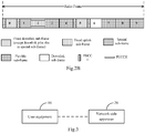
- only one fixed uplink sub-frame may be set in a radio frame, that is, the sub-frame 2 is set as a fixed uplink sub-frame, the sub-frame 0 and the sub-frame 5 are set as fixed downlink sub-frames, the sub-frame 1 is set as a special sub-frame, the sub-frame 6 is set as a special sub-frame or a downlink sub-frame (a sub-frame with a downlink transmission direction), and the remaining sub-frames are set flexible sub-frames; Where when a sub-frame 7 is an uplink sub-frame (that is, the sub-frame 7 is a flexible sub-frame with an uplink transmission direction, i.e., a variable uplink sub-frame), the sub-frame 6 is a special sub-frame, and the structure of the radio frame is as illustrated in Fig.
- the sub-frame 7 is a downlink sub-frame (that is, the sub-frame 7 is a flexible sub-frame with a downlink transmission direction, i.e., a variable downlink sub-frame)
- the sub-frame 6 is a downlink sub-frame (i.e., a sub-frame with a downlink transmission direction)
- the structure of the radio frame is as illustrated in Fig. 2B ; and in this frame structure, the highest proportion of downlink (DL) sub-frames to uplink (UL) sub-frames that can be supported is 9:1 to thereby make an adaptive dynamic range of resources in the dynamic TDD system larger and better adapt to variable traffic.
- the embodiments of the invention propose an uplink and downlink HARQ timing relationship of a TDD system for the dynamic allocation schemes of uplink and downlink sub-frames illustrated in Fig. 2A and Fig. 2B .
- a first time division duplex communication system of an embodiment of the invention includes a user equipment 10 and a network-side apparatus 20.
- the user equipment 10 is configured to receive indication information from the network side in the sub-frame n in a radio frame and to transmit PUSCH data in at least one uplink sub-frame after the sub-frame n upon determining from the indication information that the PUSCH data needs to be transmitted to the network side; and
- the network-side apparatus 20 is configured to determine the sub-frame n to carry the indication information in the radio frame and to transmit the indication information to the user equipment in the sub-frame n;
- the sub-frame 0 and the sub-frame 5 in the radio frame are fixed downlink sub-frames
- the sub-frame 2 is a fixed uplink sub-frame
- the sub-frame 1 is a special sub-frame
- the sub-frame 6 is a special sub-frame or a downlink sub-frame
- the remaining sub-frames are flexible sub-frames which can be used for uplink or downlink transmission
- the sub-frame n is a fixed downlink sub-frame or a special sub-frame to carry the indication information
- the indication information in the embodiment of the invention includes uplink grant information and/or feedback information transmitted over a Physical Hybrid Automatic Repeat Request (HARQ) Indication Channel (PHICH), where the feedback information transmitted over the PHICH further includes an ACK feedback indicating successful transmission of the PUSCH data and an NACK feedback indicating unsuccessful transmission of the PUSCH data.
- HARQ Physical Hybrid Automatic Repeat Request
- PHICH Physical Hybrid Automatic Repeat Request Indication Channel
- the indication information received by the user equipment 10 is the uplink grant information, then it is determined that the PUSCH data needs to be transmitted to the network-side apparatus 20; and If the indication information received by the user equipment 10 is the feedback information transmitted over the PHICH, then there are two scenarios: if the feedback information is the ACK feedback indicating that the PUSCH data transmitted by the user equipment to the network-side apparatus 20 has been transmitted successfully, then the PUSCH data does not need to be retransmitted; and if the feedback information is the NACK feedback indicating that the PUSCH data transmitted by the user equipment to the network-side apparatus 20 has been transmitted unsuccessfully, then the PUSCH data needs to be retransmitted.
- the indication information includes the uplink grant information and an example where the indication information includes the feedback information transmitted over the PHICH and the feedback information is the NACK feedback.
- the indication information includes the uplink grant information
- the network-side apparatus 20 transmits the uplink grant information to the user equipment 10 in a fixed downlink sub-frame (the sub-frame 0 or the sub-frame 5) or a special sub-frame (the sub-frame 1 or the sub-frame 6); and Correspondingly the user equipment 10 determines the uplink sub-frame to transmit the PUSCH data in the following three schemes:
- Timing relationship between the uplink grant information and transmission of the PUSCH data can alternatively be represented in the form of a table as depicted in Table 1: Table 1 Dynamic TDD frame Subframe index 0 1 2 3 4 5 6 7 8 9 k PUSCH 4 6 4 6
- the user equipment 10 determines the uplink sub-frame to transmit the PUSCH data according to a first fixed relationship upon determining from the received uplink grant information that the uplink sub-frame to transmit the PUSCH data needs to be determined according to the first fixed relationship; Where the first fixed relationship includes: the uplink sub-frame to transmit the PUSCH data is the seventh sub-frame after the sub-frame n; and In a third scheme, the user equipment 10 determines the uplink sub-frame to transmit the PUSCH data according to a timing relationship between the uplink grant information and transmission of the PUSCH data and determines the uplink sub
- the uplink sub-frame, determined by the user equipment 10 according to the timing relationship between the uplink grant information and transmission of the PUSCH data, to transmit the PUSCH data is the fourth sub-frame after the sub-frame 0, i.e., the sub-frame 4 in the current radio frame
- the uplink sub-frame, to transmit the PUSCH data, determined according to the first fixed relationship is the seventh sub-frame after the sub-frame 0, i.e., the sub-frame 7 in the current radio frame, and then the user equipment 10 needs to transmit the PUSCH data in both the sub-frame 4 and the sub-frame 7 in the current radio frame.
- the uplink grant information transmitted by the network-side apparatus 20 to the user equipment 10 may indicate the scheme for the user equipment to determine the uplink sub-frame to transmit the PUSCH data;
- the network-side apparatus 20 can indicate, the scheme for the user equipment 10 to determine the uplink sub-frame to transmit the PUSCH data, in 2 bits of an UL index in the uplink grant information, for example:
- the Most Significant Bit (MSB) of 1 indicates that the uplink sub-frame to transmit the PUSCH data is determined according to the timing relationship between the uplink grant information and transmission of the PUSCH data;
- the Least Significant Bit (LSB) of 1 indicates that the uplink sub-frame to transmit the PUSCH data is determined according to the first fixed relationship; and both the MSB of 1 and the LSB of 1 indicate that the uplink sub-frames to transmit the PUSCH data are determined respectively according to the timing relationship between the uplink grant information and transmission of the PUSCH data and to the first fixed relationship.
- the embodiment of the invention will not be limited to the indication pattern described above, and other patterns that can indicate the scheme for the user equipment 10 to determine the uplink sub-frame to transmit the PUSCH data can also be applicable to the embodiment of the invention.
- the indication information includes the feedback information transmitted over the PHICH and the feedback information is NACK;
- the network-side apparatus 20 determines the sub-frame n according to a timing relationship between the feedback information and transmission of the PUSCH data;
- the network-side apparatus 20 transmits the feedback information transmitted over the PHICH in the sub-frame n upon reception of the PUSCH data from the user equipment 10 to notify the user equipment 10 of a result of data transmission; and if the feedback information is the ACK feedback, then it indicates successful transmission, and if the feedback information is the NACK feedback, then it indicates unsuccessful transmission;
- the timing relationship between the feedback information and transmission of the PUSCH data includes: If the sub-frame to carry the PUSCH data is the sub-frame 2 or the sub-frame 7, then the sub-frame n is the fourth sub-frame after the sub-frame to carry the PUSCH data, i.e., the sub-frame 6 in the current radio frame or the sub-frame 1 in the next radio frame; If the sub-frame
- the PUSCH data corresponding to the feedback information refers to the PUSCH data, corresponding to the feedback information, determined according to the timing relationship between the feedback information and transmission of the PUSCH data.
- the user equipment 10 determines the uplink sub-frame to transmit the PUSCH data according to a second fixed relationship upon determining from the sub-frame n and the sub-frame to carry the PUSCH data corresponding to the feedback information that the uplink sub-frame to transmit the PUSCH data needs to be determined according to the second fixed relationship;
- the sub-frame n to carry the feedback information is the sub-frame 0 or the sub-frame 5 and the sub-frame to carry the PUSCH data corresponding to the feedback information is the sub-frame 4 or the sub-frame 9
- the user equipment 10 determines that the sub-frame to transmit the PUSCH data needs to be determined according to the second fixed relationship;
- the second fixed relationship includes: the sub-frame to transmit the PUSCH data is the seventh sub-frame after the sub-frame n; and Correspondingly the user equipment 10 retransmits the PDSCH data to the network-side apparatus 20 in the seventh sub-frame after the sub-frame n (i.e., the sub-
- the user equipment 10 determines the sub-frame to carry the feedback information according to the timing relationship between the feedback information and transmission of the PUSCH data depicted in Table 2 and receives the corresponding feedback information in the determined sub-frame to carry the feedback information;
- the user equipment 10 determines the uplink sub-frame to carry the PUSCH data in the first scheme or the second or the third scheme described above; If the indication information received by the user equipment 10 includes only the feedback information transmitted over the PHICH, then the user equipment 10 determines the uplink sub-frame to carry the PUSCH data in the scheme A or the scheme B described above; and If the indication information received by the user equipment 10 includes the uplink grant information and the feedback information transmitted over the PHICH and the feedback information is NACK, then the following two scenarios will be further involved:
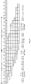
- An uplink HARQ timing relationship of a dynamic TDD system according to an embodiment of the invention is as illustrated in Fig. 4 , and in order to support backward compatibility of the dynamic TDD system according to the embodiment of the invention, that is, to allow an access of a user equipment which does not support a flexible sub-frame, e.g., a user equipment of Rel-8/9/10 or the like, the network-side apparatus 20 selects from uplink and downlink configuration processes configured for a specific user equipment (which is a user equipment which does not support a flexible sub-frame) a process, including a timing relationship between feedback information and transmission of PUSCH data, to schedule the specific user equipment; In an implementation, the network-side apparatus 20 broadcasts an uplink and downlink configuration scheme to the specific user equipment and schedules the specific user equipment in the uplink and downlink configuration scheme in a process with the same timing relationship as an uplink and downlink HARQ process of the dynamic TDD system according to the embodiment of the invention; and Since a process in the existing configuration scheme #0
- the network-side apparatus 20 allocates the uplink and downlink configuration 0 for the specific user equipment; Particularly the network-side apparatus 20 broadcasts the uplink and downlink configuration scheme #0 being currently configured for the system to the specific user equipment so that the network-side apparatus 20 can schedule the specific user equipment in all of uplink HARQ processes.
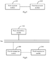
- an embodiment of the invention further provides a user equipment for time division duplex transmission of uplink data, and since the user equipment addresses the problem under a similar principle to the user equipment 10 in the system illustrated in Fig. 3 , reference can be made to the implementation of the user equipment 10 in the system illustrated in Fig. 3 for an implementation of the user equipment, so a repeated description thereof will be omitted here.
- a user equipment for time division duplex transmission of uplink data of an embodiment of the invention includes:
- a first transmission module 110 is configured to transmit PUSCH data in at least one uplink sub-frame after the sub-frame n upon determining from the indication information that the PUSCH data needs to be transmitted to the network side.
- the first transmission module 110 is particularly configured: When the indication information includes the uplink grant information, to determine the uplink sub-frame to transmit the PUSCH data according to a timing relationship between the uplink grant information and transmission of the PUSCH data upon determining from the uplink grant information that the uplink sub-frame to transmit the PUSCH data needs to be determined according to the timing relationship; or to determine the uplink sub-frame to transmit the PUSCH data according to a first fixed relationship upon determining from the uplink grant information that the uplink sub-frame to transmit the PUSCH data needs to be determined according to the first fixed relationship; or to determine the uplink sub-frame to transmit the PUSCH data according to a timing relationship between the uplink grant information and transmission of the PUSCH data and determine the uplink sub-frame to transmit the PUSCH data according to a first fixed relationship upon determining from the uplink grant information that the uplink sub-frames to transmit the PUSCH data need to be determined according to the timing relationship and the first fixed relationship.
- timing relationship between the uplink grant information and transmission of the PUSCH data includes:
- the first transmission module 110 is particularly configured: When the indication information includes the feedback information transmitted over the PHICH and the feedback information is NACK, to determine the uplink sub-frame to transmit the PUSCH data according to a timing relationship between the feedback information and retransmission of the PUSCH data upon determining from the sub-frame n and the sub-frame to carry the PUSCH data corresponding to the feedback information that the uplink sub-frame to transmit the PUSCH data needs to be determined according to the timing relationship; or to determine the uplink sub-frame to transmit the PUSCH data according to a second fixed relationship upon determining from the sub-frame n and the sub-frame to carry the PUSCH data corresponding to the feedback information that the uplink sub-frame to transmit the PUSCH data needs to be determined according to the second fixed relationship.
- the first transmission module 110 is particularly configured:
- the timing relationship between the feedback information and retransmission of the PUSCH data includes: the uplink sub-frame to transmit the PUSCH data is the fourth sub-frame after the sub-frame n; and
- the second fixed relationship includes: the sub-frame to transmit the PUSCH data is the seventh sub-frame after the sub-frame n.
- the first transmission module 110 is particularly configured:
- timing relationship between the feedback information and transmission of the PUSCH data includes:
- an embodiment of the invention further provides a network-side apparatus for time division duplex transmission of downlink data, and since the network-side apparatus addresses the problem under a similar principle to the network-side apparatus 20 in the system illustrated in Fig. 3 , reference can be made to the implementation of the network-side apparatus 20 in the system illustrated in Fig. 3 for an implementation of the network-side apparatus, so a repeated description thereof will be omitted here.
- a network-side apparatus for time division duplex transmission of downlink data includes:
- a third transmission module 210 is configured to transmit the indication information to a user equipment in the sub-frame n.
- the first determination module 200 is particularly configured: When the indication information includes the feedback information transmitted over the PHICH, to determine the sub-frame n according to a timing relationship between the feedback information and transmission of PUSCH data.
- timing relationship between the feedback information and transmission of the PUSCH data includes:
- the first network-side apparatus further comprises:
- the first compatibility module 220 is particularly configured to allocate the uplink and downlink configuration 0 for the specific user equipment.
- an embodiment of the invention further provides a method of time division duplex transmission of uplink data, and since the method addresses the problem under a similar principle to the user equipment 10 in the system illustrated in Fig. 3 , reference can be made to the implementation of the user equipment 10 in the system illustrated in Fig.3 for an implementation of the method, so a repeated description thereof will be omitted here.
- a method of time division duplex transmission of uplink data includes:
- the indication information from the network side received by the user equipment in the sub-frame n in the radio frame includes uplink grant information and/or feedback information transmitted over a PHICH, where the feedback information transmitted over the PHICH further includes an ACK feedback indicating successful transmission and an NACK feedback indicating unsuccessful transmission; and
- the user equipment transmits PUSCH data in at least one uplink sub-frame after the sub-frame n upon determining from the indication information that the PUSCH data needs to be transmitted to the network side.
- the user equipment determines that the PUSCH data needs to be transmitted to the network side; and if the indication information received by the user equipment is the feedback information transmitted over the PHICH, then there are two scenarios: if the feedback information is the ACK feedback indicating that the PUSCH data transmitted by the user equipment to the network side apparatus has been transmitted successfully, then the PUSCH data does not need to be retransmitted; and if the feedback information is the NACK feedback indicating that the PUSCH data transmitted by the user equipment to the network side apparatus has been transmitted unsuccessfully, then the user equipment needs to retransmit the PUSCH data.
- the user equipment determines from uplink sub-frames after the sub-frame n at least one uplink sub-frame to transmit the PUSCH data upon determining that the PUSCH data needs to be transmitted to the network side
- the indication information includes the uplink grant information, then the user equipment determines the uplink sub-frame to transmit the PUSCH data as follows:
- timing relationship between the uplink grant information and transmission of the PUSCH data includes:
- the first fixed relationship includes:
- the uplink sub-frame to transmit the PUSCH data is the seventh sub-frame after the sub-frame n.
- the user equipment determines the uplink sub-frame to transmit the PUSCH data as follows:
- the user equipment determines that the uplink sub-frame to transmit the PUSCH data needs to be determined according to the timing relationship in the following step:
- timing relationship between the feedback information and transmission of the PUSCH data includes:
- an embodiment of the invention further provides a method of time division duplex transmission of downlink data, and since the method addresses the problem under a similar principle to the network-side apparatus 20 in the system illustrated in Fig. 3 , reference can be made to the implementation of the network-side apparatus 20 in the system illustrated in Fig. 3 for an implementation of the method, so a repeated description thereof will be omitted here.
- a method of time division duplex reception of downlink data includes:
- the network side transmits the indication information to a user equipment in the sub-frame n.
- the network side determines the sub-frame n to carry indication information in the radio frame in the step 801 as follows: The network side determines the sub-frame n according to a timing relationship between the feedback information and transmission of PUSCH data.
- timing relationship between the feedback information and transmission of the PUSCH data includes:
- the network side allocates the uplink and downlink configuration 0 for the specific user equipment.
- a second time division duplex communication system includes:
- the network-side apparatus 40 transmits the PDSCH data to the user equipment 30 in the sub-frame to carry the PDSCH data (assumed the sub-frame m) in the radio frame
- the user equipment 30 determines the sub-frame to carry the feedback information corresponding to the PDSCH data according to the timing relationship between the feedback information and transmission of the PDSCH data upon reception of the PDSCH data in the sub-frame m in the radio frame and transmits the feedback information in the sub-frame;
- the feedback information transmitted by the user equipment 30 includes an ACK feedback indicating successful transmission of the PUSCH data and an NACK feedback indicating unsuccessful transmission of the PUSCH data.
- the timing relationship between the feedback information and transmission of the PDSCH data includes:
- Timing relationship between the feedback information and transmission of the PDSCH data can alternatively be represented in the form of a table as depicted in Table 3: Table 3 Dynamic TDD frame subframe index 0 1 2 3 4 5 6 7 8 9 k PDSCH 12 11 9 8 7 6 5 4 13
- k PDSCH -1 represents the number of sub-frames between the feedback information and transmission of the PUSCH data
- m represents the index of the sub-frame to carry the PUSCH data
- m + k PDSCH represents the k PDSCH -th after the sub-frame m which is one of the sub-frame 0, the sub-frame 1, the sub-frame 3, the sub-frame 4, the sub-frame 5, the sub-frame 6, the sub-frame 7, the sub-frame 8 and the sub-frame 9;
- the network-side apparatus 40 determines the sub-frame to carry the feedback information corresponding to the PDSCH data in the radio frame according to the timing relationship between the feedback information and transmission of the PDSCH data depicted in Table 3 after transmitting the PDSCH data to the user equipment 30 in the sub-frame m and receives the feedback information from the user equipment in the determined sub-frame.
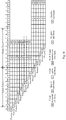
- a downlink HARQ timing relationship of a dynamic TDD system according to an embodiment of the invention is as illustrated in Fig. 10 , and in order to support backward compatibility of the dynamic TDD system according to the embodiment of the invention, that is, to allow an access of a user equipment which does not support a flexible sub-frame, e.g., a user equipment of Rel-8/9/10 or the like, the network-side apparatus 40 selects from uplink and downlink configuration processes configured for a specific user equipment (which is a user equipment which does not support a flexible sub-frame) a process, including a timing relationship between feedback information and transmission of PUSCH data, to schedule the specific user equipment; In an implementation, if the network-side apparatus 40 broadcasts the uplink and downlink configuration scheme #0 being currently configured for the system to the specific user equipment, then since only one of processes in the downlink configuration #0 has the same timing relationship with the dynamic TDD system according to the embodiment of the invention, which is the process 7 as illustrated in Fig.
- the network-side apparatus 40 can schedule the specific user equipment in that process, that is, transmit the PDSCH data in the sub-frame 6, and then correspondingly receives the feedback information (the ACK/NACK feedback) from the user equipment 30 in the sub-frame 2 in the next radio frame.
- the network-side apparatus 40 can alternatively schedule the specific user equipment in another downlink sub-frame as long as an uplink ACK/NACK feedback location available in the TDD DL/UL configuration 0 in the existing standard can be used for uplink transmission and the feedback information from the user equipment 30 can be received correctly, for example, the network-side apparatus 40 can schedule the specific user equipment in the sub-frame 0 as long as the network-side apparatus 40 can use a flexible sub-frame corresponding to the sub-frame 4 for uplink transmission.
- the functions of the communication system illustrated in Fig. 9 can be integrated with the functions of the communication system illustrated in Fig. 3 into a communication system, where the functions of the communication system illustrated in Fig. 3 will be performed when uplink and downlink data needs to be transmitted, and the functions of the communication system illustrated in Fig. 9 will be performed when uplink and downlink data needs to be received.
- an embodiment of the invention further provides a user equipment for time division duplex reception of downlink data, and since the user equipment addresses the problem under a similar principle to the user equipment in the system illustrated in Fig.9 , reference can be made to the implementation of the user equipment in the system illustrated in Fig. 9 for an implementation of the user equipment, so a repeated description thereof will be omitted here.
- a user equipment for time division duplex reception of downlink data includes:
- a second transmission module 310 is configured to determine a sub-frame to carry feedback information corresponding to the PDSCH data according to a timing relationship between the feedback information and transmission of the PDSCH data and to transmit the feedback information in the determined sub-frame.
- timing relationship between the feedback information and transmission of the PDSCH data includes:
- the functions of the user equipment illustrated in Fig. 11 can be integrated with the functions of the user equipment illustrated in Fig. 5 into a user equipment, where the functions of the user equipment illustrated in Fig. 5 will be performed when uplink data needs to be transmitted, and the functions of the user equipment illustrated in Fig. 11 will be performed when downlink data needs to be received.
- an embodiment of the invention further provides a network-side apparatus for time division duplex reception of uplink data, and since the network-side apparatus addresses the problem under a similar principle to the network-side apparatus in the system illustrated in Fig. 8 , reference can be made to the implementation of the network-side apparatus in the system illustrated in Fig. 8 for an implementation of the network-side apparatus, so a repeated description thereof will be omitted here.
- a network-side apparatus for time division duplex reception of uplink data includes:
- a third reception module 410 is configured to receive the feedback information from a user equipment in the determined sub-frame.
- timing relationship between the feedback information and transmission of the PDSCH data includes:
- the network-side apparatus further includes:
- the functions of the network-side apparatus illustrated in Fig. 12 can be integrated with the functions of the network-side apparatus illustrated in Fig. 6 into a network-side apparatus, where the functions of the network-side apparatus illustrated in Fig. 6 will be performed when downlink data needs to be transmitted, and the functions of the network-side apparatus illustrated in Fig. 12 will be performed when uplink data needs to be received.
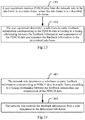
- an embodiment of the invention further provides a method of time division duplex reception of downlink data, and since the method addresses the problem under a similar principle to the user equipment in the system illustrated in Fig. 8 , reference can be made to the implementation of the user equipment in the system illustrated in Fig. 8 for an implementation of the method, so a repeated description thereof will be omitted here.
- a method of time division duplex reception of downlink data includes:
- the user equipment determines a sub-frame to carry feedback information corresponding to the PDSCH data according to a timing relationship between the feedback information and transmission of the PDSCH data and transmits the feedback information in the determined sub-frame.
- timing relationship between the feedback information and transmission of the PDSCH data includes:
- Fig. 13 and Fig. 8 can be integrated into a flow of a method of downlink communication, where the steps 801 and 802 will be performed when downlink data needs to be transmitted, and the steps 1301 and 1302 will be performed when downlink data needs to be received.
- an embodiment of the invention further provides a method of time division duplex reception of uplink data, and since the method addresses the problem under a similar principle to the network-side apparatus in the system illustrated in Fig. 9 , reference can be made to the implementation of the network-side apparatus in the system illustrated in Fig. 9 for an implementation of the method, so a repeated description thereof will be omitted here.
- a method of time division duplex transmission of downlink data includes:
- the network side receives the feedback information from a user equipment in the determined sub-frame.
- timing relationship between the feedback information and transmission of the PDSCH data includes:
- Fig. 14 and Fig. 7 can be integrated into a flow of a method of uplink communication, where the steps 701 and 702 will be performed when uplink data needs to be transmitted, and the steps 1401 and 1402 will be performed when uplink data needs to be received.
- Fig. 7, Fig. 8 , Fig. 13 and Fig. 14 can be integrated into a flow of a method of uplink and downlink communication, where the steps 701 and 702 will be performed when uplink data needs to be transmitted, the steps 801 and 802 will be performed when downlink data needs to be transmitted, the steps 1301 and 1302 will be performed when downlink data needs to be received, and the steps 1401 and 1402 will be performed when uplink data needs to be received.
- the user equipment receives the indication information from the network side in the sub-frame n in the radio frame and transmits the PUSCH data in at least one uplink sub-frame after the sub-frame n upon determining from the indication information that the PUSCH data needs to be transmitted to the network side; and in the downlink HARQ timing relationship according to the embodiments of the invention, the user equipment receives the PDSCH data from the network side in the sub-frame m in the radio frame, determines the sub-frame to carry the feedback information corresponding to the PDSCH data according to the timing relationship between the feedback information and the PDSCH data, and transmits the feedback information in the determined sub-frame, thus addressing the problem in the prior art of the absence of an HARQ timing relationship for dynamic uplink and downlink configuration and enabling the dynamic TDD system to transmit uplink and downlink data.
- the embodiments of the invention can be embodied as a method, a system or a computer program product. Therefore the invention can be embodied in the form of an all-hardware embodiment, an all-software embodiment or an embodiment of software and hardware in combination. Furthermore the invention can be embodied in the form of a computer program product embodied in one or more computer useable storage mediums (including but not limited to a disk memory, a CD-ROM, an optical memory, etc.) in which computer useable program codes are contained.
- a computer useable storage mediums including but not limited to a disk memory, a CD-ROM, an optical memory, etc.
- These computer program instructions can also be stored into a computer readable memory capable of directing the computer or the other programmable data processing device to operate in a specific manner so that the instructions stored in the computer readable memory create an article of manufacture including instruction means which perform the functions specified in the flow(s) of the flow chart and/or the block(s) of the block diagram.
- These computer program instructions can also be loaded onto the computer or the other programmable data processing device so that a series of operational steps are performed on the computer or the other programmable data processing device to create a computer implemented process so that the instructions executed on the computer or the other programmable device provide steps for performing the functions specified in the flow(s) of the flow chart and/or the block(s) of the block diagram.
Landscapes
- Engineering & Computer Science (AREA)
- Signal Processing (AREA)
- Computer Networks & Wireless Communication (AREA)
- Mobile Radio Communication Systems (AREA)
- Time-Division Multiplex Systems (AREA)
Claims (3)
- Verfahren eines Zeitmultiplexempfangs von Abwärtsdaten, wobei das Verfahren Folgendes umfasst:eine Teilnehmereinrichtung, die PDSCH-Daten von der Netzwerkseite in einem m-ten Unterrahmen, Unterrahmen m, in einem Funkrahmen empfängt, wobei der Unterrahmen 0 und der Unterrahmen 5 im Funkrahmen feste Abwärtsunterrahmen sind, der Unterrahmen 2 ein fester Aufwärtsunterrahmen ist, der Unterrahmen 1 ein spezieller Unterrahmen ist, der Unterrahmen 6 ein spezieller Unterrahmen oder ein Abwärtsunterrahmen ist, die verbleibenden Unterrahmen flexible Unterrahmen sind, die eine variable Übertragungsrichtung aufweisen, und der Unterrahmen n ein Abwärtsunterrahmen zum Transportieren der PDSCH-Daten ist (1301); undBestimmen eines Unterrahmens zum Transportieren von Rückmeldungsinformationen, die den PDSCH-Daten entsprechen, gemäß einer Zeitbeziehung zwischen den Rückmeldungsinformationen und der Übertragung der PDSCH-Daten und Übertragen der Rückmeldungsinformationen im bestimmten Unterrahmen durch die Teilnehmereinrichtung (1302) ;wobei, wenn der Unterrahmen 7 ein Aufwärtsunterrahmen ist, der Unterrahmen 6 ein spezieller Unterrahmen ist; und wenn der Unterrahmen 7 ein Abwärtsunterrahmen ist, der Unterrahmen 6 ein Abwärtsunterrahmen ist;dadurch gekennzeichnet, dassdie Zeitbeziehung zwischen den Rückmeldungsinformationen und der Übertragung der PDSCH-Daten Folgendes umfasst:wenn der Unterrahmen m der Unterrahmen 0 ist, ist der Unterrahmen zum Transportieren der Rückmeldungsinformationen der zwölfte Unterrahmen hinter dem Unterrahmen m;wenn der Unterrahmen m der Unterrahmen 1 ist, ist der Unterrahmen zum Transportieren der Rückmeldungsinformationen der elfte Unterrahmen hinter dem Unterrahmen m;wenn der Unterrahmen m der Unterrahmen 3 ist, ist der Unterrahmen zum Transportieren der Rückmeldungsinformationen der neunte Unterrahmen hinter dem Unterrahmen m;wenn der Unterrahmen m der Unterrahmen 4 ist, ist der Unterrahmen zum Transportieren der Rückmeldungsinformationen der achte Unterrahmen hinter dem Unterrahmen m;wenn der Unterrahmen m der Unterrahmen 5 ist, ist der Unterrahmen zum Transportieren der Rückmeldungsinformationen der siebte Unterrahmen hinter dem Unterrahmen m;wenn der Unterrahmen m der Unterrahmen 6 ist, ist der Unterrahmen zum Transportieren der Rückmeldungsinformationen der sechste Unterrahmen hinter dem Unterrahmen m;wenn der Unterrahmen m der Unterrahmen 7 ist, ist der Unterrahmen zum Transportieren der Rückmeldungsinformationen der fünfte Unterrahmen hinter dem Unterrahmen m;wenn der Unterrahmen m der Unterrahmen 8 ist, ist der Unterrahmen zum Transportieren der Rückmeldungsinformationen der vierte Unterrahmen hinter dem Unterrahmen m; undwenn der Unterrahmen m der Unterrahmen 9 ist, ist der Unterrahmen zum Transportieren der Rückmeldungsinformationen der dreizehnte Unterrahmen hinter dem Unterrahmen m.
- Verfahren eines Zeitmultiplexempfangs von Aufwärtsdaten, wobei das Verfahren Folgendes umfasst:Bestimmen eines Unterrahmens zum Transportieren von Rückmeldungsinformationen, die PDSCH-Daten entsprechen, in einem Funkrahmen gemäß einer Zeitbeziehung zwischen den Rückmeldungsinformationen und der Übertragung der PDSCH-Daten durch die Netzwerkseite, wobei der Unterrahmen 0 und der Unterrahmen 5 im Funkrahmen feste Abwärtsunterrahmen sind, der Unterrahmen 2 ein fester Aufwärtsunterrahmen ist, der Unterrahmen 1 ein spezieller Unterrahmen ist, der Unterrahmen 6 ein spezieller Unterrahmen oder ein Abwärtsunterrahmen ist und die verbleibenden Unterrahmen flexible Unterrahmen sind, die eine variable Übertragungsrichtung aufweisen (1401); und Empfangen der Rückmeldungsinformationen im bestimmten Unterrahmen durch die Netzwerkseite von einer Teilnehmereinrichtung (1402);wobei, wenn der Unterrahmen 7 ein Aufwärtsunterrahmen ist, der Unterrahmen 6 ein spezieller Unterrahmen ist; und wenn der Unterrahmen 7 ein Abwärtsunterrahmen ist, der Unterrahmen 6 ein Abwärtsunterrahmen ist;dadurch gekennzeichnet, dassdie Zeitbeziehung zwischen den Rückmeldungsinformationen und der Übertragung der PDSCH-Daten Folgendes umfasst:wenn der Unterrahmen zum Transportieren der PDSCH-Daten der Unterrahmen 0 ist, ist der Unterrahmen zum Transportieren der Rückmeldungsinformationen, die den PDSCH-Daten entsprechen, der zwölfte Unterrahmen hinter dem Unterrahmen zum Transportieren der PDSCH-Daten;wenn der Unterrahmen zum Transportieren der PDSCH-Daten der Unterrahmen 1 ist, ist der Unterrahmen zum Transportieren der Rückmeldungsinformationen, die den PDSCH-Daten entsprechen, der elfte Unterrahmen hinter dem Unterrahmen zum Transportieren der PDSCH-Daten;wenn der Unterrahmen zum Transportieren der PDSCH-Daten der Unterrahmen 3 ist, ist der Unterrahmen zum Transportieren der Rückmeldungsinformationen, die den PDSCH-Daten entsprechen, der neunte Unterrahmen hinter dem Unterrahmen zum Transportieren der PDSCH-Daten;wenn der Unterrahmen zum Transportieren der PDSCH-Daten der Unterrahmen 4 ist, ist der Unterrahmen zum Transportieren der Rückmeldungsinformationen, die den PDSCH-Daten entsprechen, der achte Unterrahmen hinter dem Unterrahmen zum Transportieren der PDSCH-Daten;wenn der Unterrahmen zum Transportieren der PDSCH-Daten der Unterrahmen 5 ist, ist der Unterrahmen zum Transportieren der Rückmeldungsinformationen, die den PDSCH-Daten entsprechen, der siebte Unterrahmen hinter dem Unterrahmen zum Transportieren der PDSCH-Daten;wenn der Unterrahmen zum Transportieren der PDSCH-Daten der Unterrahmen 6 ist, ist der Unterrahmen zum Transportieren der Rückmeldungsinformationen, die den PDSCH-Daten entsprechen, der sechste Unterrahmen hinter dem Unterrahmen zum Transportieren der PDSCH-Daten;wenn der Unterrahmen zum Transportieren der PDSCH-Daten der Unterrahmen 7 ist, ist der Unterrahmen zum Transportieren der Rückmeldungsinformationen, die den PDSCH-Daten entsprechen, der fünfte Unterrahmen hinter dem Unterrahmen zum Transportieren der PDSCH-Daten;wenn der Unterrahmen zum Transportieren der PDSCH-Daten der Unterrahmen 8 ist, ist der Unterrahmen zum Transportieren der Rückmeldungsinformationen, die den PDSCH-Daten entsprechen, der vierte Unterrahmen hinter dem Unterrahmen zum Transportieren der PDSCH-Daten; undwenn der Unterrahmen zum Transportieren der PDSCH-Daten der Unterrahmen 9 ist, ist der Unterrahmen zum Transportieren der Rückmeldungsinformationen, die den PDSCH-Daten entsprechen, der dreizehnte Unterrahmen hinter dem Unterrahmen zum Transportieren der PDSCH-Daten.
- Verfahren nach Anspruch 2, wobei das Verfahren ferner Folgendes umfasst:Auswählen aus Aufwärts- und Abwärtsauslegungsprozessen, die für eine spezielle Teilnehmereinrichtung ausgelegt sind, eines Prozesses, der die Zeitbeziehung zwischen den Rückmeldungsinformationen und der Übertragung der PUSCH-Daten umfasst, durch die Netzwerkseite, um die spezielle Teilnehmereinrichtung zu planen;wobei die spezielle Teilnehmereinrichtung eine Teilnehmereinrichtung ist, die einen flexiblen Unterrahmen nicht unterstützt.
Priority Applications (1)
| Application Number | Priority Date | Filing Date | Title |
|---|---|---|---|
| EP18212469.3A EP3477875B1 (de) | 2012-03-23 | 2013-03-06 | Zeitduplex-kommunikationsverfahren, -system und -vorrichtung |
Applications Claiming Priority (2)
| Application Number | Priority Date | Filing Date | Title |
|---|---|---|---|
| CN201210080085XA CN103326840A (zh) | 2012-03-23 | 2012-03-23 | 一种时分双工通信的方法、系统和设备 |
| PCT/CN2013/072243 WO2013139208A1 (zh) | 2012-03-23 | 2013-03-06 | 一种时分双工通信的方法、系统和设备 |
Related Child Applications (2)
| Application Number | Title | Priority Date | Filing Date |
|---|---|---|---|
| EP18212469.3A Division-Into EP3477875B1 (de) | 2012-03-23 | 2013-03-06 | Zeitduplex-kommunikationsverfahren, -system und -vorrichtung |
| EP18212469.3A Division EP3477875B1 (de) | 2012-03-23 | 2013-03-06 | Zeitduplex-kommunikationsverfahren, -system und -vorrichtung |
Publications (3)
| Publication Number | Publication Date |
|---|---|
| EP2830236A1 EP2830236A1 (de) | 2015-01-28 |
| EP2830236A4 EP2830236A4 (de) | 2015-03-18 |
| EP2830236B1 true EP2830236B1 (de) | 2019-02-27 |
Family
ID=49195390
Family Applications (2)
| Application Number | Title | Priority Date | Filing Date |
|---|---|---|---|
| EP18212469.3A Active EP3477875B1 (de) | 2012-03-23 | 2013-03-06 | Zeitduplex-kommunikationsverfahren, -system und -vorrichtung |
| EP13764633.7A Active EP2830236B1 (de) | 2012-03-23 | 2013-03-06 | Zeitduplex-kommunikationsverfahren, system und vorrichtung |
Family Applications Before (1)
| Application Number | Title | Priority Date | Filing Date |
|---|---|---|---|
| EP18212469.3A Active EP3477875B1 (de) | 2012-03-23 | 2013-03-06 | Zeitduplex-kommunikationsverfahren, -system und -vorrichtung |
Country Status (6)
| Country | Link |
|---|---|
| US (1) | US10080236B2 (de) |
| EP (2) | EP3477875B1 (de) |
| JP (3) | JP6077098B2 (de) |
| KR (1) | KR101572957B1 (de) |
| CN (1) | CN103326840A (de) |
| WO (1) | WO2013139208A1 (de) |
Families Citing this family (18)
| Publication number | Priority date | Publication date | Assignee | Title |
|---|---|---|---|---|
| WO2015024215A1 (en) * | 2013-08-21 | 2015-02-26 | Qualcomm Incorporated | Pucch resource mapping an harq-ack feedback |
| US9642162B2 (en) * | 2013-10-22 | 2017-05-02 | Acer Incorporated | Signaling method to configure multiple carriers used by wireless device and base station in carrier aggregation operation |
| CN105164964A (zh) * | 2013-11-11 | 2015-12-16 | 华为技术有限公司 | 上行混合自动重传请求的反馈方法、系统和相关设备 |
| WO2015089745A1 (zh) * | 2013-12-17 | 2015-06-25 | 华为技术有限公司 | 一种获取、配置子帧结构的方法及网络设备 |
| EP3105866A4 (de) * | 2014-02-13 | 2017-10-25 | ZTE Corporation | Verfahren und vorrichtung zur bestimmung eines flexiblen unterrahmentyps in einem lte-tdd-system |
| CN110896346B (zh) * | 2014-04-03 | 2022-02-25 | 华为技术有限公司 | 传输pusch的方法、用户设备和基站 |
| WO2015154310A1 (zh) * | 2014-04-11 | 2015-10-15 | 华为技术有限公司 | 一种控制信道资源分配方法及装置 |
| CN110430028B (zh) * | 2014-06-27 | 2021-09-07 | 华为技术有限公司 | Pusch的传输方法及装置 |
| JP2017529015A (ja) * | 2014-09-25 | 2017-09-28 | 富士通株式会社 | 半2重通信システムにおけるサブフレームスケジューリング方法、データ送受信方法、装置及びシステム |
| BR112018003099A2 (pt) | 2015-08-25 | 2018-09-25 | Nokia Solutions And Networks Oy | configuração de quadro de rádio |
| WO2017113206A1 (zh) | 2015-12-30 | 2017-07-06 | 华为技术有限公司 | 一种数据通信的方法、终端设备及网络设备 |
| JP2019091958A (ja) | 2016-03-30 | 2019-06-13 | シャープ株式会社 | 端末装置、基地局装置、通信方法、および、集積回路 |
| CN107528676B (zh) * | 2016-06-22 | 2020-02-11 | 电信科学技术研究院 | 一种上行传输的反馈信息的传输方法和设备 |
| CN107733598B (zh) * | 2016-08-11 | 2021-04-06 | 中国移动通信有限公司研究院 | 一种消息传输方法、用户设备及基站 |
| CN108282883B (zh) * | 2017-01-06 | 2020-03-24 | 电信科学技术研究院 | 一种信息传输方法及装置 |
| CN110769505B (zh) | 2018-07-26 | 2023-04-18 | 维沃移动通信有限公司 | 随机接入方法、终端及网络设备 |
| CN110536270B (zh) * | 2018-09-28 | 2023-09-01 | 中兴通讯股份有限公司 | 数据发送、接收方法、装置、终端、基站及存储介质 |
| CN111726864B (zh) * | 2019-03-21 | 2023-07-18 | 华为技术有限公司 | 通信方法、装置 |
Citations (1)
| Publication number | Priority date | Publication date | Assignee | Title |
|---|---|---|---|---|
| US20110085478A1 (en) * | 2008-10-24 | 2011-04-14 | Huawei Technologies Co., Ltd. | Relay Transmission Method and Apparatus |
Family Cites Families (14)
| Publication number | Priority date | Publication date | Assignee | Title |
|---|---|---|---|---|
| CN101472305B (zh) | 2007-12-26 | 2012-01-25 | 电信科学技术研究院 | 一种实现小区切换的方法、系统及装置 |
| KR20100139062A (ko) | 2008-03-24 | 2010-12-31 | 지티이 (유에스에이) 인크. | Lte/τdd 시스템에서의 다운링크/업링크 할당 비율의 동적 조정 및 시그널링 |
| US9294219B2 (en) * | 2008-09-30 | 2016-03-22 | Qualcomm Incorporated | Techniques for supporting relay operation in wireless communication systems |
| CN102204154B (zh) * | 2008-10-31 | 2014-05-21 | 诺基亚公司 | 在基于分组的无线通信系统中用于时分双工操作的子帧调度的动态分配 |
| US8982767B2 (en) | 2009-05-12 | 2015-03-17 | Lg Electronics Inc. | Method for transceiving data with both a mobile station and a relay station in a broadband wireless communication system |
| TWI486018B (zh) * | 2009-10-23 | 2015-05-21 | Ind Tech Res Inst | 無線中繼轉傳系統的傳送方法及其中繼台 |
| US8559343B2 (en) | 2009-12-23 | 2013-10-15 | Telefonaktiebolaget Lm Ericsson (Publ) | Flexible subframes |
| US20110176461A1 (en) | 2009-12-23 | 2011-07-21 | Telefonakatiebolaget Lm Ericsson (Publ) | Determining configuration of subframes in a radio communications system |
| US8699386B2 (en) | 2010-08-18 | 2014-04-15 | Qualcomm Incorporated | H-ARQ timing and backhaul subframe configuration for TDD relay in LTE-A |
| CN102064879B (zh) * | 2010-11-30 | 2014-05-07 | 大唐移动通信设备有限公司 | 一种时分双工通信的方法、系统和设备 |
| KR101820742B1 (ko) * | 2011-05-30 | 2018-01-22 | 삼성전자 주식회사 | 이동 통신 시스템 및 그 시스템에서 데이터 전송 방법 |
| CN102223214B (zh) * | 2011-06-01 | 2014-04-16 | 电信科学技术研究院 | 一种数据传输的方法及装置 |
| CN102201859B (zh) * | 2011-06-03 | 2013-10-02 | 电信科学技术研究院 | 一种数据传输的方法及装置 |
| CN102231662B (zh) * | 2011-06-03 | 2013-05-08 | 电信科学技术研究院 | 一种数据传输的方法及装置 |
-
2012
- 2012-03-23 CN CN201210080085XA patent/CN103326840A/zh active Pending
-
2013
- 2013-03-06 KR KR1020147029729A patent/KR101572957B1/ko active Active
- 2013-03-06 EP EP18212469.3A patent/EP3477875B1/de active Active
- 2013-03-06 US US14/387,542 patent/US10080236B2/en active Active
- 2013-03-06 EP EP13764633.7A patent/EP2830236B1/de active Active
- 2013-03-06 WO PCT/CN2013/072243 patent/WO2013139208A1/zh not_active Ceased
- 2013-03-06 JP JP2015500752A patent/JP6077098B2/ja active Active
-
2016
- 2016-07-26 JP JP2016146776A patent/JP2017017714A/ja active Pending
- 2016-07-26 JP JP2016146777A patent/JP6284590B2/ja active Active
Patent Citations (1)
| Publication number | Priority date | Publication date | Assignee | Title |
|---|---|---|---|---|
| US20110085478A1 (en) * | 2008-10-24 | 2011-04-14 | Huawei Technologies Co., Ltd. | Relay Transmission Method and Apparatus |
Also Published As
| Publication number | Publication date |
|---|---|
| KR20140136055A (ko) | 2014-11-27 |
| US10080236B2 (en) | 2018-09-18 |
| JP2017017714A (ja) | 2017-01-19 |
| JP2017005730A (ja) | 2017-01-05 |
| KR101572957B1 (ko) | 2015-11-27 |
| WO2013139208A1 (zh) | 2013-09-26 |
| EP3477875A1 (de) | 2019-05-01 |
| JP6077098B2 (ja) | 2017-02-08 |
| US20150049654A1 (en) | 2015-02-19 |
| CN103326840A (zh) | 2013-09-25 |
| EP2830236A1 (de) | 2015-01-28 |
| EP2830236A4 (de) | 2015-03-18 |
| EP3477875B1 (de) | 2020-04-29 |
| JP2015512574A (ja) | 2015-04-27 |
| JP6284590B2 (ja) | 2018-02-28 |
Similar Documents
| Publication | Publication Date | Title |
|---|---|---|
| EP2830236B1 (de) | Zeitduplex-kommunikationsverfahren, system und vorrichtung | |
| KR102142580B1 (ko) | 동기 복합 자동 재전송 요구 송신을 지원하는 방법 및 장치 | |
| EP2907338B1 (de) | Kommunikationsknoten | |
| EP3155749B1 (de) | Harq-verfahren und rahmenstruktur für lte-zellen auf nichtlizenziertem spektrum | |
| US9935758B2 (en) | Method for allocating uplink ACK/NACK channels | |
| EP2654235B1 (de) | HARQ zum dynamischen Ändern der TTD-UL/DL-Konfiguration in LTE-TDD-Systemen | |
| EP2697921B1 (de) | Verfahren und vorrichtung zum betreiben von subframes und zum übertragen von kanalinformationen zur interferenzsteuerung in einem kommunikationssystem | |
| EP2538734B1 (de) | Verfahren und vorrichtung zur zeitplanung mehrerer unterrahmen | |
| EP2676394B1 (de) | Mobilkommunikationssystem und kanalsende-/empfangsverfahren dafür | |
| EP2944116B1 (de) | Drahtloses kommunikationssystem, basisstation und verfahren darin | |
| KR102081937B1 (ko) | 장치 대 장치 통신 방법 및 이를 수행하기 위한 장치 | |
| EP2695312B1 (de) | Flexible anpassung der konfiguration von uplink- und downlink-verhältnis | |
| KR101820742B1 (ko) | 이동 통신 시스템 및 그 시스템에서 데이터 전송 방법 | |
| EP3142264A1 (de) | Verfahren und vorrichtung zur datenkommunikation in einem kommunikationssystem | |
| US20140307597A1 (en) | Method and apparatus for controlling transceiving of physical channels in time division duplex communication system | |
| EP2663008B1 (de) | Verfahren, benutzervorrichtung und basisstation zur informationsübertragung in einem zeitteilungs-duplexsystem | |
| EP3478011B1 (de) | Verfahren und vorrichtung für datenübertragung eines gemeinsam genutzten physikalischen uplink-kanals | |
| KR20140141575A (ko) | 이동통신 시스템에서 반이중(half duplex)전송을 지원하는 단말과 관련된 채널 송수신 방법 및 장치 | |
| CN109155712A (zh) | 借助时分双工的多发射时间间隔协调 | |
| CN105122677A (zh) | 将资源分配给使用相同频带的多个站点的方法和装置 | |
| US9332529B2 (en) | Physical downlink shared channel transmission method | |
| KR20130143531A (ko) | 무선 통신 시스템에서 업링크 스케쥴링 방법 및 장치 | |
| KR20180017940A (ko) | 무선 셀룰라 통신 시스템에서 지연감소를 위한 전송 방법 및 장치 | |
| CN105577333B (zh) | 一种确定中继链路harq时序关系的方法 | |
| KR20140047914A (ko) | Tdd 시스템에서 제어 채널 전송 방법 및 장치 |
Legal Events
| Date | Code | Title | Description |
|---|---|---|---|
| PUAI | Public reference made under article 153(3) epc to a published international application that has entered the european phase |
Free format text: ORIGINAL CODE: 0009012 |
|
| 17P | Request for examination filed |
Effective date: 20141023 |
|
| AK | Designated contracting states |
Kind code of ref document: A1 Designated state(s): AL AT BE BG CH CY CZ DE DK EE ES FI FR GB GR HR HU IE IS IT LI LT LU LV MC MK MT NL NO PL PT RO RS SE SI SK SM TR |
|
| AX | Request for extension of the european patent |
Extension state: BA ME |
|
| A4 | Supplementary search report drawn up and despatched |
Effective date: 20150218 |
|
| RIC1 | Information provided on ipc code assigned before grant |
Ipc: H04B 7/26 20060101AFI20150212BHEP |
|
| DAX | Request for extension of the european patent (deleted) | ||
| 17Q | First examination report despatched |
Effective date: 20160503 |
|
| STAA | Information on the status of an ep patent application or granted ep patent |
Free format text: STATUS: EXAMINATION IS IN PROGRESS |
|
| GRAP | Despatch of communication of intention to grant a patent |
Free format text: ORIGINAL CODE: EPIDOSNIGR1 |
|
| STAA | Information on the status of an ep patent application or granted ep patent |
Free format text: STATUS: GRANT OF PATENT IS INTENDED |
|
| INTG | Intention to grant announced |
Effective date: 20180924 |
|
| GRAS | Grant fee paid |
Free format text: ORIGINAL CODE: EPIDOSNIGR3 |
|
| GRAA | (expected) grant |
Free format text: ORIGINAL CODE: 0009210 |
|
| STAA | Information on the status of an ep patent application or granted ep patent |
Free format text: STATUS: THE PATENT HAS BEEN GRANTED |
|
| AK | Designated contracting states |
Kind code of ref document: B1 Designated state(s): AL AT BE BG CH CY CZ DE DK EE ES FI FR GB GR HR HU IE IS IT LI LT LU LV MC MK MT NL NO PL PT RO RS SE SI SK SM TR |
|
| REG | Reference to a national code |
Ref country code: GB Ref legal event code: FG4D |
|
| REG | Reference to a national code |
Ref country code: CH Ref legal event code: EP |
|
| REG | Reference to a national code |
Ref country code: AT Ref legal event code: REF Ref document number: 1102856 Country of ref document: AT Kind code of ref document: T Effective date: 20190315 |
|
| REG | Reference to a national code |
Ref country code: IE Ref legal event code: FG4D |
|
| REG | Reference to a national code |
Ref country code: DE Ref legal event code: R096 Ref document number: 602013051436 Country of ref document: DE |
|
| REG | Reference to a national code |
Ref country code: NL Ref legal event code: MP Effective date: 20190227 |
|
| REG | Reference to a national code |
Ref country code: LT Ref legal event code: MG4D |
|
| PG25 | Lapsed in a contracting state [announced via postgrant information from national office to epo] |
Ref country code: NL Free format text: LAPSE BECAUSE OF FAILURE TO SUBMIT A TRANSLATION OF THE DESCRIPTION OR TO PAY THE FEE WITHIN THE PRESCRIBED TIME-LIMIT Effective date: 20190227 Ref country code: LT Free format text: LAPSE BECAUSE OF FAILURE TO SUBMIT A TRANSLATION OF THE DESCRIPTION OR TO PAY THE FEE WITHIN THE PRESCRIBED TIME-LIMIT Effective date: 20190227 Ref country code: PT Free format text: LAPSE BECAUSE OF FAILURE TO SUBMIT A TRANSLATION OF THE DESCRIPTION OR TO PAY THE FEE WITHIN THE PRESCRIBED TIME-LIMIT Effective date: 20190627 Ref country code: SE Free format text: LAPSE BECAUSE OF FAILURE TO SUBMIT A TRANSLATION OF THE DESCRIPTION OR TO PAY THE FEE WITHIN THE PRESCRIBED TIME-LIMIT Effective date: 20190227 Ref country code: NO Free format text: LAPSE BECAUSE OF FAILURE TO SUBMIT A TRANSLATION OF THE DESCRIPTION OR TO PAY THE FEE WITHIN THE PRESCRIBED TIME-LIMIT Effective date: 20190527 Ref country code: FI Free format text: LAPSE BECAUSE OF FAILURE TO SUBMIT A TRANSLATION OF THE DESCRIPTION OR TO PAY THE FEE WITHIN THE PRESCRIBED TIME-LIMIT Effective date: 20190227 |
|
| PG25 | Lapsed in a contracting state [announced via postgrant information from national office to epo] |
Ref country code: IS Free format text: LAPSE BECAUSE OF FAILURE TO SUBMIT A TRANSLATION OF THE DESCRIPTION OR TO PAY THE FEE WITHIN THE PRESCRIBED TIME-LIMIT Effective date: 20190627 Ref country code: BG Free format text: LAPSE BECAUSE OF FAILURE TO SUBMIT A TRANSLATION OF THE DESCRIPTION OR TO PAY THE FEE WITHIN THE PRESCRIBED TIME-LIMIT Effective date: 20190527 Ref country code: GR Free format text: LAPSE BECAUSE OF FAILURE TO SUBMIT A TRANSLATION OF THE DESCRIPTION OR TO PAY THE FEE WITHIN THE PRESCRIBED TIME-LIMIT Effective date: 20190528 Ref country code: HR Free format text: LAPSE BECAUSE OF FAILURE TO SUBMIT A TRANSLATION OF THE DESCRIPTION OR TO PAY THE FEE WITHIN THE PRESCRIBED TIME-LIMIT Effective date: 20190227 Ref country code: RS Free format text: LAPSE BECAUSE OF FAILURE TO SUBMIT A TRANSLATION OF THE DESCRIPTION OR TO PAY THE FEE WITHIN THE PRESCRIBED TIME-LIMIT Effective date: 20190227 Ref country code: LV Free format text: LAPSE BECAUSE OF FAILURE TO SUBMIT A TRANSLATION OF THE DESCRIPTION OR TO PAY THE FEE WITHIN THE PRESCRIBED TIME-LIMIT Effective date: 20190227 |
|
| REG | Reference to a national code |
Ref country code: AT Ref legal event code: MK05 Ref document number: 1102856 Country of ref document: AT Kind code of ref document: T Effective date: 20190227 |
|
| PG25 | Lapsed in a contracting state [announced via postgrant information from national office to epo] |
Ref country code: ES Free format text: LAPSE BECAUSE OF FAILURE TO SUBMIT A TRANSLATION OF THE DESCRIPTION OR TO PAY THE FEE WITHIN THE PRESCRIBED TIME-LIMIT Effective date: 20190227 Ref country code: SK Free format text: LAPSE BECAUSE OF FAILURE TO SUBMIT A TRANSLATION OF THE DESCRIPTION OR TO PAY THE FEE WITHIN THE PRESCRIBED TIME-LIMIT Effective date: 20190227 Ref country code: RO Free format text: LAPSE BECAUSE OF FAILURE TO SUBMIT A TRANSLATION OF THE DESCRIPTION OR TO PAY THE FEE WITHIN THE PRESCRIBED TIME-LIMIT Effective date: 20190227 Ref country code: CZ Free format text: LAPSE BECAUSE OF FAILURE TO SUBMIT A TRANSLATION OF THE DESCRIPTION OR TO PAY THE FEE WITHIN THE PRESCRIBED TIME-LIMIT Effective date: 20190227 Ref country code: IT Free format text: LAPSE BECAUSE OF FAILURE TO SUBMIT A TRANSLATION OF THE DESCRIPTION OR TO PAY THE FEE WITHIN THE PRESCRIBED TIME-LIMIT Effective date: 20190227 Ref country code: EE Free format text: LAPSE BECAUSE OF FAILURE TO SUBMIT A TRANSLATION OF THE DESCRIPTION OR TO PAY THE FEE WITHIN THE PRESCRIBED TIME-LIMIT Effective date: 20190227 Ref country code: AL Free format text: LAPSE BECAUSE OF FAILURE TO SUBMIT A TRANSLATION OF THE DESCRIPTION OR TO PAY THE FEE WITHIN THE PRESCRIBED TIME-LIMIT Effective date: 20190227 Ref country code: DK Free format text: LAPSE BECAUSE OF FAILURE TO SUBMIT A TRANSLATION OF THE DESCRIPTION OR TO PAY THE FEE WITHIN THE PRESCRIBED TIME-LIMIT Effective date: 20190227 |
|
| REG | Reference to a national code |
Ref country code: CH Ref legal event code: PL |
|
| REG | Reference to a national code |
Ref country code: DE Ref legal event code: R097 Ref document number: 602013051436 Country of ref document: DE |
|
| PG25 | Lapsed in a contracting state [announced via postgrant information from national office to epo] |
Ref country code: LU Free format text: LAPSE BECAUSE OF NON-PAYMENT OF DUE FEES Effective date: 20190306 Ref country code: PL Free format text: LAPSE BECAUSE OF FAILURE TO SUBMIT A TRANSLATION OF THE DESCRIPTION OR TO PAY THE FEE WITHIN THE PRESCRIBED TIME-LIMIT Effective date: 20190227 Ref country code: SM Free format text: LAPSE BECAUSE OF FAILURE TO SUBMIT A TRANSLATION OF THE DESCRIPTION OR TO PAY THE FEE WITHIN THE PRESCRIBED TIME-LIMIT Effective date: 20190227 |
|
| REG | Reference to a national code |
Ref country code: BE Ref legal event code: MM Effective date: 20190331 |
|
| PG25 | Lapsed in a contracting state [announced via postgrant information from national office to epo] |
Ref country code: AT Free format text: LAPSE BECAUSE OF FAILURE TO SUBMIT A TRANSLATION OF THE DESCRIPTION OR TO PAY THE FEE WITHIN THE PRESCRIBED TIME-LIMIT Effective date: 20190227 Ref country code: MC Free format text: LAPSE BECAUSE OF FAILURE TO SUBMIT A TRANSLATION OF THE DESCRIPTION OR TO PAY THE FEE WITHIN THE PRESCRIBED TIME-LIMIT Effective date: 20190227 |
|
| PLBE | No opposition filed within time limit |
Free format text: ORIGINAL CODE: 0009261 |
|
| STAA | Information on the status of an ep patent application or granted ep patent |
Free format text: STATUS: NO OPPOSITION FILED WITHIN TIME LIMIT |
|
| PG25 | Lapsed in a contracting state [announced via postgrant information from national office to epo] |
Ref country code: CH Free format text: LAPSE BECAUSE OF NON-PAYMENT OF DUE FEES Effective date: 20190331 Ref country code: LI Free format text: LAPSE BECAUSE OF NON-PAYMENT OF DUE FEES Effective date: 20190331 Ref country code: IE Free format text: LAPSE BECAUSE OF NON-PAYMENT OF DUE FEES Effective date: 20190306 |
|
| 26N | No opposition filed |
Effective date: 20191128 |
|
| PG25 | Lapsed in a contracting state [announced via postgrant information from national office to epo] |
Ref country code: BE Free format text: LAPSE BECAUSE OF NON-PAYMENT OF DUE FEES Effective date: 20190331 Ref country code: SI Free format text: LAPSE BECAUSE OF FAILURE TO SUBMIT A TRANSLATION OF THE DESCRIPTION OR TO PAY THE FEE WITHIN THE PRESCRIBED TIME-LIMIT Effective date: 20190227 |
|
| PG25 | Lapsed in a contracting state [announced via postgrant information from national office to epo] |
Ref country code: TR Free format text: LAPSE BECAUSE OF FAILURE TO SUBMIT A TRANSLATION OF THE DESCRIPTION OR TO PAY THE FEE WITHIN THE PRESCRIBED TIME-LIMIT Effective date: 20190227 |
|
| PG25 | Lapsed in a contracting state [announced via postgrant information from national office to epo] |
Ref country code: MT Free format text: LAPSE BECAUSE OF NON-PAYMENT OF DUE FEES Effective date: 20190306 |
|
| PG25 | Lapsed in a contracting state [announced via postgrant information from national office to epo] |
Ref country code: CY Free format text: LAPSE BECAUSE OF FAILURE TO SUBMIT A TRANSLATION OF THE DESCRIPTION OR TO PAY THE FEE WITHIN THE PRESCRIBED TIME-LIMIT Effective date: 20190227 |
|
| PG25 | Lapsed in a contracting state [announced via postgrant information from national office to epo] |
Ref country code: HU Free format text: LAPSE BECAUSE OF FAILURE TO SUBMIT A TRANSLATION OF THE DESCRIPTION OR TO PAY THE FEE WITHIN THE PRESCRIBED TIME-LIMIT; INVALID AB INITIO Effective date: 20130306 |
|
| REG | Reference to a national code |
Ref country code: DE Ref legal event code: R081 Ref document number: 602013051436 Country of ref document: DE Owner name: DATANG MOBILE COMMUNICATIONS EQUIPMENT CO., LT, CN Free format text: FORMER OWNER: CHINA ACADEMY OF TELECOMMUNICATIONS TECHNOLOGY, BEIJING, CN |
|
| REG | Reference to a national code |
Ref country code: GB Ref legal event code: 732E Free format text: REGISTERED BETWEEN 20211007 AND 20211013 |
|
| PG25 | Lapsed in a contracting state [announced via postgrant information from national office to epo] |
Ref country code: MK Free format text: LAPSE BECAUSE OF FAILURE TO SUBMIT A TRANSLATION OF THE DESCRIPTION OR TO PAY THE FEE WITHIN THE PRESCRIBED TIME-LIMIT Effective date: 20190227 |
|
| P01 | Opt-out of the competence of the unified patent court (upc) registered |
Effective date: 20230512 |
|
| PGFP | Annual fee paid to national office [announced via postgrant information from national office to epo] |
Ref country code: GB Payment date: 20260324 Year of fee payment: 14 |
|
| PGFP | Annual fee paid to national office [announced via postgrant information from national office to epo] |
Ref country code: DE Payment date: 20260319 Year of fee payment: 14 |
|
| PGFP | Annual fee paid to national office [announced via postgrant information from national office to epo] |
Ref country code: FR Payment date: 20260320 Year of fee payment: 14 |