EP2830456B1 - Dispositif qui donne du volume aux cheveux et qui utilise des dents individuelles sans laisser de motif visible - Google Patents
Dispositif qui donne du volume aux cheveux et qui utilise des dents individuelles sans laisser de motif visible Download PDFInfo
- Publication number
- EP2830456B1 EP2830456B1 EP13769532.6A EP13769532A EP2830456B1 EP 2830456 B1 EP2830456 B1 EP 2830456B1 EP 13769532 A EP13769532 A EP 13769532A EP 2830456 B1 EP2830456 B1 EP 2830456B1
- Authority
- EP
- European Patent Office
- Prior art keywords
- hair
- teeth
- individual teeth
- interlocking
- interlocking plate
- Prior art date
- Legal status (The legal status is an assumption and is not a legal conclusion. Google has not performed a legal analysis and makes no representation as to the accuracy of the status listed.)
- Active
Links
Images


Classifications
-
- A—HUMAN NECESSITIES
- A45—HAND OR TRAVELLING ARTICLES
- A45D—HAIRDRESSING OR SHAVING EQUIPMENT; EQUIPMENT FOR COSMETICS OR COSMETIC TREATMENTS, e.g. FOR MANICURING OR PEDICURING
- A45D2/00—Hair-curling or hair-waving appliances ; Appliances for hair dressing treatment not otherwise provided for
- A45D2/38—Surface-wave devices
- A45D2/40—Surface-wave devices as hair-pressing tongs
Definitions
- the invention relates to hair treatment devices used for styling a person's hair. More particularly, the invention relates to a hair volumizing device that creates the outward appearance of greater hair volume without leaving an outwardly visible pattern.
- Existing hair treatment devices include a category of devices that crimp hair. These crimping devices, known as crimping irons or crimpers, impart a series of bends or creases to the hair. There are two uses of such crimping devices. A first use, and common use, is to impart a visible crimp pattern to the top layer of the hair as a distinct hairstyle, this is known as a crimped hairstyle and this process is known as crimping. A second use, as described in US Patent 7,992,578 is to use a crimping device to create the appearance of volume to a person's hair. This is done by applying the crimping device to an under layer of the hair.
- An under layer of hair is a layer of hair that is covered by an upper layer of hair and has at least a portion that is an interior hair layer that is not visible in a hair style because an upper layer of hair rests on top and hides it from view.
- the under layer of hair is crimped. This causes the upper layer of hair to be lifted and held away from the head, creating the appearance of greater hair volume. This is because the outer layer of hair rests on the under layer further away from the head and scalp than it would have rested when the under layer was not crimped. Thus the upper layer is lifted and creates the appearance of more hair volume.
- This lifting application of the device has been accomplished heretofore by repurposing the first use of the crimping device of creating a distinct pattern in the visible hair and using the same crimping device on an under layer of hair and not on the upper visible layer of hair.
- a crimping application requires that the crimping device impart a distinct crimped pattern to the hair, which does, as a secondary effect, create somewhat greater volume in the hair.
- a volumizing application requires the creation of a firm support structure in the under layer of hair that can be sustained while supporting the upper layer of hair, giving the appearance of significantly greater hair volume; and that little or no discernible pattern or texture be visible, thereby leaving the basic hair style unchanged.
- Current hair treatment devices are not specifically designed for lifting and volumizing and do not meet these requirements.
- crimping devices such as in US Patent 7,992,578
- These crimping devices employ a single row of long columnar, saw-tooth shaped raised teeth on heated mating and interlocking plates, which are embedded in a handheld device that is clamped briefly on the hair.
- the columnar teeth in these devices extend the entire length of the heated interlocking plates.
- the columnar teeth run parallel to the long axis of the device.
- any hair treatment device with columnar teeth of any shape will leave a distinct pattern in the hair when used in a volumizing application due to the length and regularity of the folds that are created in the hair. Since a goal of a hair treatment device used in a volumizing application is to create lift and volume without creating a visibly crimped hairstyle, any use of columnar teeth, sawtooth or other profile, in such a device is undesirable.
- a second problem with the columnar teeth pattern in crimping devices is that it is not able to create a firm support structure in the lower layers of hair capable of supporting the upper hair layers when used in a volumizing application. This is because the sharp, saw-tooth shaped columnar teeth create a series of sharp, accordion pleats in the hair that unfold or collapse under the weight of the upper hair layers resting on them and no longer aid in volumizing the hair.
- a third problem with existing crimping devices is that the tooth height is not adequate to lift the hair significantly up and away from the head and scalp, in order to create the appearance of substantially greater hair volume.
- a fourth problem with prior art is the undesirable appearance of frizzy hair from the crimped under layer poking through to the upper layers of hair, caused by the use of closely-spaced, jagged, saw-tooth columnar teeth. Frizzy hair appears dull, kinky, and unhealthy.
- GB2415624 describes a hairstyling device having two arms pivoted at a hinge and having upper and lower hair contacting plates.
- the plates have surface profiles comprising projections and recessions that cooperate when the arms are brought together.
- WO 2007/079217 describes a hair treatment device for providing lift at the root portion of the hair.
- FR 2,153,788 describes a clamp for creating surface designs in a hairstyle.
- JP399502 describes a hair-styling device capable of stretching and compensating hair sandwiched between heated clips.
- US2001/0022184 describes a hair iron that includes a pair of arms connected by a pivot, each arm having a gripping portion and a hair treatment portion.
- An embodiment of the invention provides a hair treatment device that is optimized for lifting and volumizing hair.
- the volumizing device leaves little or no visible pattern or frizz in the hair and creates significantly greater and longer lasting volume in the hair. These benefits are achieved through a tooth design that employs arrays of outwardly projecting individual teeth arranged in a two-dimensional array pattern, in a checkerboard pattern such as described in claim 1, instead of long, regular columnar, parallel teeth.
- the volumizing device may be for use by end users on their own hair as well as users on the hair of others, such as in salons by stylists and hair technicians.
- the hair volumizing device allows users to impart significant volume or lift to hair by creating a three-dimensional matrix of hair in the under layers of the hair that serves to lift portions of the upper layers of the hair away from the head, creating the appearance of greater hair volume, without creating a clearly visible pattern in the hair.
- An under layer of hair is a portion of hair that is not visible in a hairstyle because it is located beneath the upper layers of hair that comprise the hair visible to others in a hairstyle.
- a comb may be used to part the hair slightly below the point where the user typically parts the hair.
- the upper hair is separated and hair clips may be used to keep it out of the way while the under layer is being treated.
- the selected under layer of hair is then treated with the volumizing device. This process can be repeated all over the head in order to lift hair away from the scalp, giving the appearance of greater hair volume.
- Users may treat only the portion of hair closest to where it leaves the scalp or they may additionally treat hair as far down the hair shaft as they desire.
- a volumizing sub-structure in the under layers of the hair is created by clamping the hair between the interlocking plates of the volumizing device, which are made up of arrays of outwardly projecting individual teeth.
- the plates are heated and briefly clamped on the under layers of hair in order to create structural support for the upper layers.
- Fig. 1 shows a volumizing device 1 that consists of a pair of arms 2 and 3 that are joined by a pivot 7. At one end of each arm there is an interlocking plate 4 and 5, and at another end of each arm there is a handle portion 8.
- the pivot is a hinge, such as a barrel hinge or floating hinge, that allows for the interlocking plates to be clamped together in a parallel fashion.
- the pivot joins the arms at an end of the arm such that the interlocking plate and handle portion of each arm are not separated by the pivot.
- the pivot joins the arms such that the interlocking plate and handle portion of each arm are located on opposite sides of the pivot.
- the interlocking plates have a long axis in the direction of the length of the arms and a short axis in the direction of the width of the arms. Either or both of the interlocking plates are heated by a heating element located within the arm.
- the heating element heats an interlocking plate by any conventional heating method including, for example, electrical resistance, induction, infrared, combustion, or steam.
- the heating element heats an interlocking plate to an operating temperature from about 250°F to about 430°F.
- the temperature, as well as an on/off function, in some embodiments is controlled by an analog or digital circuit located, for example, within an arm of the device.
- the device is powered by an internal power supply, such as a battery.
- the device is powered by an external source through a power cord 9.
- the interlocking plates have a complementary design such that, when the ends of the arms at which they are located are clamped together, the interlocking plates interlock with each other, as shown in Fig. 2 .
- the individual teeth on an interlocking plate mesh with complementary teeth on the other interlocking plate.
- the interlocking plates clamp on an under layer of hair and at least one of the interlocking plates is heated in order to set the hair in a shape determined by the shape of the interlocking plates.
- Each interlocking plate consists of a two-dimensional array of separated individual teeth 10 separated on all sides by spaces 11.
- the embodiments of Figs. 1 , 2 , 3, 4, and 5 show the individual teeth arranged in a checkerboard fashion in rows and columns.
- an individual tooth consists of a square prism with flats sides 12 and a flat top 13 surrounded on each of its four sides 12 by a space 11 that is also of square prism shape and similarly sized to the individual tooth.
- the individual teeth can be arranged in any regular pattern or in an irregular array, which then does not form part of the invention. As shown in Fig.
- the teeth 10 on each plate interlock with the complementary spaces 11 on the opposite, mating interlocking plate.
- the teeth on opposing plate pairs have a pattern or array that is the inverse of the opposing plate.
- a plate has more spaces than teeth and, when the interlocking plates interlock, a space on one plate has a complementary space, instead of a complementary tooth, on the other plate.
- Fig. 6 shows a cross section of the individual teeth from Fig. 4 while the device is in use, with a hair 14 being bent or folded in an alternating tooth and gap in the checkerboard pattern found in the embodiment of Figs. 1 , and 2 .
- the array of alternating gap and tooth design not only creates a strong support structure in the lower layers of hair, but it also does this without creating a clear pattern that is visible in the upper layer as is the case using known crimping devices. This is because each tooth creates a firm support pier in the hair that alternates with surrounding recessed piers, thus breaking up and obscuring any clear pattern of folds in the hair. This is in sharp contrast to the long, accordion pleat folds left in the hair by the long, columnar teeth of known crimping devices, which leave a clear pleated or crimped pattern that is visible in the upper layers of hair.
- Fig. 1 shows each plate having 6 columns and 18 rows, however the number of rows and columns can be as few as two and as many as 20 or greater.
- the height of the teeth ranges from about 4 to about 25 mm, but it may exceed this if it is desired to achieve the appearance of even more volume. Further in embodiments, the height of teeth on the same or complementary interlocking plates may vary.
- the teeth are rectangular prisms having square bases and flat square tops.
- the long axis length of each tooth may range from about 4 mm to about 25 mm and short axis length from about 4 mm to about 25 mm, although other dimensions are within the scope of the invention.
- the teeth arrangement leaves small gaps between the teeth on one plate and the teeth on the other plate to fit the hair that is treated and bent or folded, as shown.
- the complementary individual teeth of the interlocking plates comprise gaps that accommodate an amount of hair intended to be treated at once. Thus, the gap may be made larger or smaller to accommodate various amounts of hair to be treated.
- the width of the interlocking plate ranges from about 8 mm for short hair and up to about 75 mm or more for longer hair.
- the long axis length of the plate ranges from about 12 mm to about 125 mm or more.
- Fig. 8 shows a cross section of an embodiment with trapezoid teeth 15 with a flat top surface.
- the trapezoid teeth are arranged in a checkerboard pattern as described in claim 1 and function similarly to the square teeth of the embodiment shown in Fig. 1 .
- Fig. 9 shows a diamond or an angled tooth 16 pattern in a checkerboard-like embodiment with flat top tooth surfaces.
- the shape of the tops and the bases of the individual teeth are rectangular, square, diamond, trapezoidal, round, oval, elliptical, triangular, pentagonal, hexagonal, or any other polygon or geometric shape.
- the individual teeth are prisms, truncated prisms, antiprisms, pyramids, flat-topped pyramids, and other polyhedrons. Further, in these embodiments the teeth are individual teeth surrounded by spaces and projecting from the surface of the interlocking plate.
- Non-rectilinear designs such as those shown in Fig. 10 of curved teeth 17 are also within the scope of the invention, as long as they fall within the scope of claim 1.
- the teeth are S-shaped, or other curved shapes and consist of individual and separated teeth that are arranged in patterns, such as in rows and columns.
- the teeth are arranged in a variety of patterns. These arrangements include rows and columns not parallel to either the long or short axes of the interlocking plate. Further, in some embodiments rows or columns of teeth are not parallel to other rows or columns of teeth and are not in a symmetrical pattern of rows and columns. In some embodiments the teeth are in a spiral pattern, a zig-zag pattern, a radial pattern, or any combination thereof. In some embodiments the teeth are arranged in a two dimensional array on an interlocking plate in an irregular or random pattern. In addition in some embodiments, a variety of tooth patterns co-exist on the same interlocking plate, in different sections of the plate. In some embodiments complementary interlocking plates have different shaped teeth and different patterns of teeth that mesh and interlock with one another.
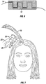
- Fig. 7 shows a table-type support 18, created by the flat top surface of the individual teeth of an interlocking plate, and an array of piers with table-type supports providing a foundation for support to the upper layers 19 of hair.
- the individual, alternating teeth that form the piers break up the pattern in the hair making it less visible, while adding to the strength of the foundation.
- Each individual tooth comprises a flat top surface.
- the top surfaces of the teeth are smooth, ridged, textured, uneven, stepped, or any combination thereof.
- the sides 12 of the individual teeth shown in the embodiment in Fig. 1 have flat sides projecting perpendicular from the interlocking plate and the individual teeth shown in the embodiment in Fig. 8 have flat sides projecting at an obtuse angle to the interlocking plate.
- the sides of a tooth all project from the interlocking plate at the same angle and in some embodiments at least one side of a tooth projects from the interlocking plate at an angle different than at least one of the other sides of the tooth.
- the sides of the individual teeth are curved, stepped, faceted or textured.
- each plate has any combination of types of individual teeth 22, 23, with varying or similar size, heights, shapes, top surfaces, and types of sides, which form part of the invention as long as they fall within the scope of claim 1.
- a device has interchangeable plates with different types of individual teeth, with varying or similar size, heights, shapes, top surfaces, and types of sides.
- the interchangeable plates are in pairs of complementary plates, and in some embodiments an interlocking plate has a plurality of complementary plates with different individual tooth configurations.
- the interlocking plates are flat and rectangular, as shown in the embodiment in Fig. 1 .
- the interlocking plates are curved along either of their axes or both.
- the interlocking plates have both curved and flat sections.
- the interlocking plates are non rectangular in shape, including, for example, interlocking plates in the shape of circles, ovals, triangles, and other polygons and geometric shapes. The plate shape is independent of the pattern of the individual teeth.
- a circular interlocking plate has a checkerboard tooth pattern and in some embodiments a rectangular plate has a checkerboard tooth pattern, as described in claim 1.
- the overall device including the arms, and the interlocking plates are straight, similar to existing crimping devices, and in some embodiments the overall device or components thereof are curved, including, for example, along the long or short axes of the arms.
- a curved volumizing device is curved to be better adapted to more easily reach the back of the head or to match the curvature of the head.
- the overall device is made of smaller components to suit travel applications.
- the travel version has as few as two columns of individual separate teeth in any of the above described patterns.
- the construction of the interlocking plate is made of ceramic or metal, including, for example, aluminum, aluminum alloys, copper, steel, iron, zinc and nickel alloys.
- the metals are coated with various materials, including, for example, silicone, anodized metal, Teflon, ceramics, including, for example, tourmaline and titanium-infused ceramics or some combination thereof.
- the teeth have both thermally conductive and insulating layers and contain materials designed to create friction to help hold the hair in place during treatment. Fabrication of the interlocking plates and teeth is done with any manufacturing method, including, for example, die casting, mold casting, extrusion, milling, drawing, laser cutting, and other metal forming and fabrication methods.
- the device 1 consists of two mating, heated interlocking plates 4 and 5 that clamp and interlock in a jaw-like fashion onto the under layers of the hair 20 as shown in Fig. 12 .
- the interlocking plates consist of separate and individual teeth arranged in a two dimensional array or pattern as described above. When the plates are clamped together as shown in Figs. 2 and 6 the teeth arrangement provides small gaps between the plates in order to fit the treated hair.
- Fig. 12 shows a hair treatment device in use on a person's hair with the plate and teeth design described here.
- each treated hair is bent over each tooth, creating discrete bends, folds or creases in the hair.
- the hinging of the device enables the mating interlocking plates to meet in a parallel fashion when clamped on the hair.
- each tooth will bend the hair from about 60 to about 120 degree angles, multiple times per tooth.
- each tooth will bend a strand of hair 14 at 90-degree angles, a total of four times per tooth as shown in Fig. 6 .
- each tooth will create a raised flat surface 18 in the under hair layer 20 for the upper hair layer 19 to rest on and a lower flat surface 21 that rests against the scalp or other hair in order to provide a firm support for the upper layer of hair.
- a strong three-dimensional support matrix of piers is created in the under layer of treated hair, which supports the upper layer which remains untreated by the volumizing device. This process can be repeated as far down the hair shaft as desired and around the entire head of hair. Further the process may be repeated so that multiple layers of under layers of hair create support matrices that are stacked onto each other to create even greater volume in the user's hair.
- portions of hair that are folded along a given row serve to support the neighboring hair portions in adjacent rows that are folded in the opposite direction.
- These alternating hair folds create a strong foundation of support due to a grid of flat topped piers that are more stable and less likely than hair treated with columnar teeth, found in crimping devices, to collapse in a domino cascading fashion.
- This system also minimizes the spans between piers, so that the upper or outer layer of hair is better supported.
- This individual tooth arrangement creates a more laterally stable platform to hold the upper hair up and away from the head or scalp, thereby adding the volume desired and holding it for long periods of time.
- This alternating tooth checkerboard design provides this support without leaving a distinct visible pattern in the hair, due to the individual, flat-topped teeth and their alternating arrangement on the interlocking plates. Because each tooth alternates with gaps on all sides, any clear pattern of folding in the hair created by each raised tooth is broken up and obscured by the adjacent gaps between the teeth, especially when concealed beneath an upper layer of hair not treated by the volumizing device. This is in contrast to the long, sharp-peaked, accordion pleated folds left in the hair by the long, saw tooth columnar teeth of a crimping device, which leave a clear pleated or crimped pattern that is clearly visible in the upper layers of hair.
- the device creates volume and lift without creating undesired frizz in the lower layers that protrudes into the upper visible layers.
- a segment of hair is placed over the entire active surface of the interlocking plate, and clamped briefly between two interlocking plates, a strong three-dimensional support system is created in the lower layer of treated hair that supports the upper visible layer.
- the outer or upper hair layer remains untreated. This process can be repeated as far down the hair shaft as desired, thereby building volume on the top and on the sides of the head for a long-haired user. It can also be repeated in an under layer close to the scalp, over the entire head of hair, adding volume in the back of the head.
- these plates impart to the hair a foundation of strong support designed to create, lift and add volume in hair, while minimizing a visible pattern in the hair and without creating undesired frizz.
Landscapes
- Brushes (AREA)
- Hair Curling (AREA)
- Scissors And Nippers (AREA)
Claims (10)
- Dispositif pour donner du volume aux cheveux, comprenant :un premier bras (2) comprenant une première plaque d'interverrouillage (4) ;un second bras (3) comprenant une seconde plaque d'interverrouillage (5) ;au moins un élément chauffant associé à l'une quelconque de ladite première plaque d'interverrouillage (4) et de ladite seconde plaque d'interverrouillage (5) ; etun pivot (7) positionné entre ledit premier bras (2) et ledit second bras (3) et agencé pour permettre un mouvement relatif des plaques d'interverrouillage (4, 5) entre une position interverrouillée et une position qui n'est pas interverrouillée ;ladite première et ladite seconde plaque d'interverrouillage comprenant chacune un réseau bidimensionnel de dents individuelles (10) en projection vers l'extérieur ;dans lequel le réseau de dents individuelles (10) qui se projettent vers l'extérieur de la première plaque d'interverrouillage (4) est complémentaire en termes d'interverrouillage au réseau de dents individuelles (10) qui se projettent vers l'extérieur de la seconde plaque d'interverrouillage (5) ;caractérisé en ce quechaque dent individuelle (10) comprend une surface supérieure plane (13) et soit comprend une forme en prisme carré soit est une dent trapézoïdale ; eten ce que le réseau bidimensionnel de dents individuelles (10) comprend un motif en échiquier dans lequel chaque dent individuelle (10) est entourée sur chacun de ses côtés par un espace (11) qui présente une taille et une forme similaires à la dent individuelle (10).
- Dispositif selon la revendication, dans lequel la dent individuelle (10) comprend des prismes rectangulaires.
- Dispositif selon la revendication 1, dans lequel les dents individuelles (10) comprennent :une surface supérieure parallèle à la plaque d'interverrouillage (4, 5), etdes côtés qui se projettent à la perpendiculaire (12) depuis les plaques d'interverrouillage.
- Dispositif selon la revendication 1, dans lequel au moins une dent individuelle (10) comprend :
au moins un côté en angle qui se projette depuis la plaque d'interverrouillage sous un angle non perpendiculaire (15). - Dispositif selon la revendication 1, dans lequel les dents individuelles (10) comprennent des prismes qui se projettent depuis la plaque d'interverrouillage (4, 5).
- Dispositif selon la revendication 1, dans lequel les bases des dents individuelles (10) ont la forme de polygones réguliers.
- Dispositif selon la revendication 1, dans lequel les dents individuelles comprennent des prismes tronqués.
- Dispositif selon la revendication 1, dans lequel au moins une plaque d'interverrouillage (4, 5) comprend des dents individuelles (10) d'au moins deux formes différentes.
- Dispositif selon la revendication 1, dans lequel les réseaux bidimensionnels de dents individuelles (10) sur les plaques d'interverrouillage (4, 5) sont conformés pour créer une matrice tridimensionnelle de surfaces planes dressées dans une couche inférieure des cheveux capable de supporter une couche de cheveux supérieure.
- Dispositif selon la revendication 1, dans lequel, lorsqu'elles sont dans la position interverrouillée, les dents individuelles (10) sur la première plaque d'interverrouillage (4) ne sont pas en contact avec les dents individuelles sur la seconde plaque d'interverrouillage (5) et sont séparées par un intervalle.
Applications Claiming Priority (4)
| Application Number | Priority Date | Filing Date | Title |
|---|---|---|---|
| US201261616955P | 2012-03-28 | 2012-03-28 | |
| US201261637688P | 2012-04-24 | 2012-04-24 | |
| US13/707,423 US8839802B2 (en) | 2012-03-28 | 2012-12-06 | Hair volumizing device that employs individual teeth without leaving a visible pattern |
| PCT/US2013/034162 WO2013148876A1 (fr) | 2012-03-28 | 2013-03-27 | Dispositif qui donne du volume aux cheveux et qui utilise des dents individuelles sans laisser de motif visible |
Publications (3)
| Publication Number | Publication Date |
|---|---|
| EP2830456A1 EP2830456A1 (fr) | 2015-02-04 |
| EP2830456A4 EP2830456A4 (fr) | 2015-12-16 |
| EP2830456B1 true EP2830456B1 (fr) | 2018-10-03 |
Family
ID=49233225
Family Applications (1)
| Application Number | Title | Priority Date | Filing Date |
|---|---|---|---|
| EP13769532.6A Active EP2830456B1 (fr) | 2012-03-28 | 2013-03-27 | Dispositif qui donne du volume aux cheveux et qui utilise des dents individuelles sans laisser de motif visible |
Country Status (12)
| Country | Link |
|---|---|
| US (1) | US8839802B2 (fr) |
| EP (1) | EP2830456B1 (fr) |
| JP (1) | JP5911084B2 (fr) |
| KR (1) | KR101493666B1 (fr) |
| CN (2) | CN107981510B (fr) |
| AU (1) | AU2013239681B2 (fr) |
| BR (1) | BR112014023618B1 (fr) |
| CA (1) | CA2916992C (fr) |
| ES (1) | ES2704085T3 (fr) |
| IN (1) | IN2014DN08937A (fr) |
| MX (1) | MX2014011592A (fr) |
| WO (1) | WO2013148876A1 (fr) |
Families Citing this family (9)
| Publication number | Priority date | Publication date | Assignee | Title |
|---|---|---|---|---|
| US8607803B2 (en) * | 2011-09-29 | 2013-12-17 | The Procter & Gamble Company | Hair treatment process providing dispersed colors by light diffraction |
| US20130263883A1 (en) * | 2012-03-19 | 2013-10-10 | Dana Story | Curling iron |
| US20150027486A1 (en) * | 2012-03-28 | 2015-01-29 | Oomph Innovations, Llc | Hair volumizing device that utilizes individual treatment elements without leaving a visible pattern |
| US8839802B2 (en) * | 2012-03-28 | 2014-09-23 | Oomph Innovations, Llc | Hair volumizing device that employs individual teeth without leaving a visible pattern |
| USD760953S1 (en) * | 2015-09-16 | 2016-07-05 | E. Mishan & Sons, Inc. | Hair volumizer |
| CN109431042B (zh) * | 2018-12-27 | 2024-06-25 | 品谱公司 | 一种偏角式扭纹头发造型器 |
| KR102051249B1 (ko) * | 2019-02-14 | 2019-12-02 | 심수지 | 헤어 볼륨 생성 장치 |
| CN222091020U (zh) * | 2022-11-03 | 2024-12-03 | 沙龙工作室有限责任公司 | 烫发系统 |
| KR102903431B1 (ko) * | 2024-10-10 | 2025-12-24 | 한정현 | 휴대용 모발 스타일링 장치 |
Family Cites Families (23)
| Publication number | Priority date | Publication date | Assignee | Title |
|---|---|---|---|---|
| US1221447A (en) * | 1916-10-25 | 1917-04-03 | Mabel A C Henderson | Hair-waver. |
| US1465383A (en) | 1920-03-17 | 1923-08-21 | Frank J Walsh | Composite lumber |
| US1465838A (en) * | 1921-08-01 | 1923-08-21 | Caneavri Joseph Ping | Hair iron |
| US2626618A (en) * | 1950-06-16 | 1953-01-27 | Curtis L Collison | Comb |
| FR2153788A5 (fr) * | 1971-09-24 | 1973-05-04 | Cousty Jacques | |
| JPS5251274U (fr) * | 1975-10-08 | 1977-04-12 | ||
| LU86196A1 (fr) * | 1985-12-06 | 1987-07-24 | Faco Sa | Pince a coiffer electrique |
| JPH0371390U (fr) * | 1989-11-17 | 1991-07-18 | ||
| JP2516484Y2 (ja) * | 1990-01-25 | 1996-11-06 | 小島化学株式会社 | 頭髪補整器 |
| JP3000262B2 (ja) * | 1996-05-23 | 2000-01-17 | 豊作 瀧前 | 縮れ毛矯正アイロン |
| SE512684C2 (sv) * | 1998-07-09 | 2000-05-02 | Volumaster Ab | Anordning för hår och en hårtång med en sådan anordning |
| US6119702A (en) * | 1999-02-26 | 2000-09-19 | Habibi; Masood | Heated hair styling system |
| KR20010088269A (ko) * | 2000-03-10 | 2001-09-26 | 이만택 | 헤어 아이론 |
| US6708699B2 (en) * | 2001-06-13 | 2004-03-23 | Mcgriff, Iii Alphonso | Apparatus and method for grooming dreadlocks |
| EP1516554B1 (fr) * | 2003-09-19 | 2007-11-14 | Naomoto Industry Co., Ltd. | Fer à friser |
| KR200364344Y1 (ko) * | 2004-06-28 | 2004-10-11 | 주식회사 와이에스크리에이션 | 전기 고데기 |
| JP2006346071A (ja) | 2005-06-15 | 2006-12-28 | Mokku Co Ltd | ヘアーアイロン |
| JP4839800B2 (ja) * | 2005-11-25 | 2011-12-21 | パナソニック電工株式会社 | 超音波ヘアセット器 |
| US7992578B2 (en) * | 2005-12-30 | 2011-08-09 | Andrew J Tobias | Hair treatment device |
| US20110017225A1 (en) * | 2009-07-22 | 2011-01-27 | Venkata Parimal Devulapalli | Hair styling tool with two or more rotatable multipurpose-platforms |
| ITMI20091946A1 (it) * | 2009-11-06 | 2011-05-07 | Tenacta Group Spa | Dispositivo per arricciare e/o modellare i capelli |
| KR200460916Y1 (ko) * | 2010-03-16 | 2012-06-13 | 김상안 | 머리 미용기구 |
| US8839802B2 (en) * | 2012-03-28 | 2014-09-23 | Oomph Innovations, Llc | Hair volumizing device that employs individual teeth without leaving a visible pattern |
-
2012
- 2012-12-06 US US13/707,423 patent/US8839802B2/en active Active
-
2013
- 2013-03-27 MX MX2014011592A patent/MX2014011592A/es unknown
- 2013-03-27 JP JP2015503544A patent/JP5911084B2/ja active Active
- 2013-03-27 CN CN201711062184.4A patent/CN107981510B/zh active Active
- 2013-03-27 IN IN8937DEN2014 patent/IN2014DN08937A/en unknown
- 2013-03-27 WO PCT/US2013/034162 patent/WO2013148876A1/fr not_active Ceased
- 2013-03-27 CA CA2916992A patent/CA2916992C/fr active Active
- 2013-03-27 KR KR1020147029948A patent/KR101493666B1/ko active Active
- 2013-03-27 BR BR112014023618-6A patent/BR112014023618B1/pt active IP Right Grant
- 2013-03-27 CN CN201380027880.5A patent/CN104334049B/zh active Active
- 2013-03-27 AU AU2013239681A patent/AU2013239681B2/en active Active
- 2013-03-27 ES ES13769532T patent/ES2704085T3/es active Active
- 2013-03-27 EP EP13769532.6A patent/EP2830456B1/fr active Active
Non-Patent Citations (1)
| Title |
|---|
| None * |
Also Published As
| Publication number | Publication date |
|---|---|
| JP2015512306A (ja) | 2015-04-27 |
| IN2014DN08937A (fr) | 2015-05-22 |
| BR112014023618A2 (pt) | 2020-06-02 |
| JP5911084B2 (ja) | 2016-04-27 |
| AU2013239681B2 (en) | 2015-09-17 |
| US20130255715A1 (en) | 2013-10-03 |
| AU2013239681A1 (en) | 2014-11-13 |
| CN107981510B (zh) | 2021-12-28 |
| KR20140135262A (ko) | 2014-11-25 |
| EP2830456A4 (fr) | 2015-12-16 |
| US8839802B2 (en) | 2014-09-23 |
| CA2916992A1 (fr) | 2013-10-03 |
| WO2013148876A1 (fr) | 2013-10-03 |
| CN107981510A (zh) | 2018-05-04 |
| EP2830456A1 (fr) | 2015-02-04 |
| MX2014011592A (es) | 2014-11-21 |
| HK1206567A1 (en) | 2016-01-15 |
| ES2704085T3 (es) | 2019-03-14 |
| CN104334049A (zh) | 2015-02-04 |
| CA2916992C (fr) | 2016-11-29 |
| KR101493666B1 (ko) | 2015-02-13 |
| CN104334049B (zh) | 2022-01-11 |
| BR112014023618B1 (pt) | 2021-09-21 |
Similar Documents
| Publication | Publication Date | Title |
|---|---|---|
| EP2830456B1 (fr) | Dispositif qui donne du volume aux cheveux et qui utilise des dents individuelles sans laisser de motif visible | |
| US20150027486A1 (en) | Hair volumizing device that utilizes individual treatment elements without leaving a visible pattern | |
| CN1112873C (zh) | 卷发装置以及带有这种装置的卷发夹具 | |
| KR20150129690A (ko) | 헤어 스타일링 디바이스 | |
| EP2720572B1 (fr) | Fer à friser | |
| CN102196741A (zh) | 一种卷发装置 | |
| HK1206567B (zh) | 使用单独的齿形而不留下可见图案的蓬发装置 | |
| KR20120054897A (ko) | 스트레이트 및 웨이브 성형이 가능한 헤어 아이론 | |
| CN215837520U (zh) | 美发器 | |
| CN202211313U (zh) | 非标准椭圆柱阶梯型烫发杠 | |
| CN202396736U (zh) | 自动卷发器 | |
| JP3133788U (ja) | 半円形の基体の丸み部分にのみ雄型係合素子を有したヘアーカーラー。 | |
| JP3217835U (ja) | パーマ用ロッド部材 | |
| WO2015082868A1 (fr) | Améliorations apportées à des dispositifs d'ondulation de cheveux | |
| KR101124416B1 (ko) | 퍼머용 롯드 및 이 롯드에 모발을 와인딩하는 방법 | |
| JPS5917204Y2 (ja) | メツシユコ−ム | |
| CN102885459A (zh) | 非标准椭圆柱阶梯型烫发杠 | |
| JP2011104130A (ja) | 変形くし | |
| JPH0245008A (ja) | パンチパーマ用アイロン |
Legal Events
| Date | Code | Title | Description |
|---|---|---|---|
| PUAI | Public reference made under article 153(3) epc to a published international application that has entered the european phase |
Free format text: ORIGINAL CODE: 0009012 |
|
| 17P | Request for examination filed |
Effective date: 20141028 |
|
| AK | Designated contracting states |
Kind code of ref document: A1 Designated state(s): AL AT BE BG CH CY CZ DE DK EE ES FI FR GB GR HR HU IE IS IT LI LT LU LV MC MK MT NL NO PL PT RO RS SE SI SK SM TR |
|
| AX | Request for extension of the european patent |
Extension state: BA ME |
|
| DAX | Request for extension of the european patent (deleted) | ||
| RA4 | Supplementary search report drawn up and despatched (corrected) |
Effective date: 20151117 |
|
| RIC1 | Information provided on ipc code assigned before grant |
Ipc: A45D 2/40 20060101AFI20151111BHEP |
|
| STAA | Information on the status of an ep patent application or granted ep patent |
Free format text: STATUS: EXAMINATION IS IN PROGRESS |
|
| 17Q | First examination report despatched |
Effective date: 20170807 |
|
| GRAP | Despatch of communication of intention to grant a patent |
Free format text: ORIGINAL CODE: EPIDOSNIGR1 |
|
| STAA | Information on the status of an ep patent application or granted ep patent |
Free format text: STATUS: GRANT OF PATENT IS INTENDED |
|
| INTG | Intention to grant announced |
Effective date: 20180420 |
|
| RIN1 | Information on inventor provided before grant (corrected) |
Inventor name: LUND, PATRICIA A. Inventor name: SCHWARTZ, WILLIAM M. |
|
| GRAS | Grant fee paid |
Free format text: ORIGINAL CODE: EPIDOSNIGR3 |
|
| GRAJ | Information related to disapproval of communication of intention to grant by the applicant or resumption of examination proceedings by the epo deleted |
Free format text: ORIGINAL CODE: EPIDOSDIGR1 |
|
| GRAL | Information related to payment of fee for publishing/printing deleted |
Free format text: ORIGINAL CODE: EPIDOSDIGR3 |
|
| STAA | Information on the status of an ep patent application or granted ep patent |
Free format text: STATUS: EXAMINATION IS IN PROGRESS |
|
| GRAR | Information related to intention to grant a patent recorded |
Free format text: ORIGINAL CODE: EPIDOSNIGR71 |
|
| STAA | Information on the status of an ep patent application or granted ep patent |
Free format text: STATUS: GRANT OF PATENT IS INTENDED |
|
| GRAA | (expected) grant |
Free format text: ORIGINAL CODE: 0009210 |
|
| STAA | Information on the status of an ep patent application or granted ep patent |
Free format text: STATUS: THE PATENT HAS BEEN GRANTED |
|
| INTC | Intention to grant announced (deleted) | ||
| INTG | Intention to grant announced |
Effective date: 20180823 |
|
| AK | Designated contracting states |
Kind code of ref document: B1 Designated state(s): AL AT BE BG CH CY CZ DE DK EE ES FI FR GB GR HR HU IE IS IT LI LT LU LV MC MK MT NL NO PL PT RO RS SE SI SK SM TR |
|
| REG | Reference to a national code |
Ref country code: GB Ref legal event code: FG4D |
|
| REG | Reference to a national code |
Ref country code: CH Ref legal event code: EP Ref country code: AT Ref legal event code: REF Ref document number: 1047683 Country of ref document: AT Kind code of ref document: T Effective date: 20181015 |
|
| REG | Reference to a national code |
Ref country code: IE Ref legal event code: FG4D Ref country code: DE Ref legal event code: R096 Ref document number: 602013044526 Country of ref document: DE |
|
| REG | Reference to a national code |
Ref country code: NL Ref legal event code: FP |
|
| REG | Reference to a national code |
Ref country code: LT Ref legal event code: MG4D |
|
| REG | Reference to a national code |
Ref country code: ES Ref legal event code: FG2A Ref document number: 2704085 Country of ref document: ES Kind code of ref document: T3 Effective date: 20190314 |
|
| REG | Reference to a national code |
Ref country code: AT Ref legal event code: MK05 Ref document number: 1047683 Country of ref document: AT Kind code of ref document: T Effective date: 20181003 |
|
| PG25 | Lapsed in a contracting state [announced via postgrant information from national office to epo] |
Ref country code: FI Free format text: LAPSE BECAUSE OF FAILURE TO SUBMIT A TRANSLATION OF THE DESCRIPTION OR TO PAY THE FEE WITHIN THE PRESCRIBED TIME-LIMIT Effective date: 20181003 Ref country code: BG Free format text: LAPSE BECAUSE OF FAILURE TO SUBMIT A TRANSLATION OF THE DESCRIPTION OR TO PAY THE FEE WITHIN THE PRESCRIBED TIME-LIMIT Effective date: 20190103 Ref country code: PL Free format text: LAPSE BECAUSE OF FAILURE TO SUBMIT A TRANSLATION OF THE DESCRIPTION OR TO PAY THE FEE WITHIN THE PRESCRIBED TIME-LIMIT Effective date: 20181003 Ref country code: CZ Free format text: LAPSE BECAUSE OF FAILURE TO SUBMIT A TRANSLATION OF THE DESCRIPTION OR TO PAY THE FEE WITHIN THE PRESCRIBED TIME-LIMIT Effective date: 20181003 Ref country code: AT Free format text: LAPSE BECAUSE OF FAILURE TO SUBMIT A TRANSLATION OF THE DESCRIPTION OR TO PAY THE FEE WITHIN THE PRESCRIBED TIME-LIMIT Effective date: 20181003 Ref country code: LT Free format text: LAPSE BECAUSE OF FAILURE TO SUBMIT A TRANSLATION OF THE DESCRIPTION OR TO PAY THE FEE WITHIN THE PRESCRIBED TIME-LIMIT Effective date: 20181003 Ref country code: NO Free format text: LAPSE BECAUSE OF FAILURE TO SUBMIT A TRANSLATION OF THE DESCRIPTION OR TO PAY THE FEE WITHIN THE PRESCRIBED TIME-LIMIT Effective date: 20190103 Ref country code: IS Free format text: LAPSE BECAUSE OF FAILURE TO SUBMIT A TRANSLATION OF THE DESCRIPTION OR TO PAY THE FEE WITHIN THE PRESCRIBED TIME-LIMIT Effective date: 20190203 Ref country code: HR Free format text: LAPSE BECAUSE OF FAILURE TO SUBMIT A TRANSLATION OF THE DESCRIPTION OR TO PAY THE FEE WITHIN THE PRESCRIBED TIME-LIMIT Effective date: 20181003 Ref country code: LV Free format text: LAPSE BECAUSE OF FAILURE TO SUBMIT A TRANSLATION OF THE DESCRIPTION OR TO PAY THE FEE WITHIN THE PRESCRIBED TIME-LIMIT Effective date: 20181003 |
|
| PG25 | Lapsed in a contracting state [announced via postgrant information from national office to epo] |
Ref country code: AL Free format text: LAPSE BECAUSE OF FAILURE TO SUBMIT A TRANSLATION OF THE DESCRIPTION OR TO PAY THE FEE WITHIN THE PRESCRIBED TIME-LIMIT Effective date: 20181003 Ref country code: SE Free format text: LAPSE BECAUSE OF FAILURE TO SUBMIT A TRANSLATION OF THE DESCRIPTION OR TO PAY THE FEE WITHIN THE PRESCRIBED TIME-LIMIT Effective date: 20181003 Ref country code: RS Free format text: LAPSE BECAUSE OF FAILURE TO SUBMIT A TRANSLATION OF THE DESCRIPTION OR TO PAY THE FEE WITHIN THE PRESCRIBED TIME-LIMIT Effective date: 20181003 Ref country code: GR Free format text: LAPSE BECAUSE OF FAILURE TO SUBMIT A TRANSLATION OF THE DESCRIPTION OR TO PAY THE FEE WITHIN THE PRESCRIBED TIME-LIMIT Effective date: 20190104 Ref country code: PT Free format text: LAPSE BECAUSE OF FAILURE TO SUBMIT A TRANSLATION OF THE DESCRIPTION OR TO PAY THE FEE WITHIN THE PRESCRIBED TIME-LIMIT Effective date: 20190203 |
|
| REG | Reference to a national code |
Ref country code: DE Ref legal event code: R097 Ref document number: 602013044526 Country of ref document: DE |
|
| PG25 | Lapsed in a contracting state [announced via postgrant information from national office to epo] |
Ref country code: DK Free format text: LAPSE BECAUSE OF FAILURE TO SUBMIT A TRANSLATION OF THE DESCRIPTION OR TO PAY THE FEE WITHIN THE PRESCRIBED TIME-LIMIT Effective date: 20181003 |
|
| PLBE | No opposition filed within time limit |
Free format text: ORIGINAL CODE: 0009261 |
|
| STAA | Information on the status of an ep patent application or granted ep patent |
Free format text: STATUS: NO OPPOSITION FILED WITHIN TIME LIMIT |
|
| PG25 | Lapsed in a contracting state [announced via postgrant information from national office to epo] |
Ref country code: EE Free format text: LAPSE BECAUSE OF FAILURE TO SUBMIT A TRANSLATION OF THE DESCRIPTION OR TO PAY THE FEE WITHIN THE PRESCRIBED TIME-LIMIT Effective date: 20181003 Ref country code: RO Free format text: LAPSE BECAUSE OF FAILURE TO SUBMIT A TRANSLATION OF THE DESCRIPTION OR TO PAY THE FEE WITHIN THE PRESCRIBED TIME-LIMIT Effective date: 20181003 Ref country code: SK Free format text: LAPSE BECAUSE OF FAILURE TO SUBMIT A TRANSLATION OF THE DESCRIPTION OR TO PAY THE FEE WITHIN THE PRESCRIBED TIME-LIMIT Effective date: 20181003 Ref country code: SM Free format text: LAPSE BECAUSE OF FAILURE TO SUBMIT A TRANSLATION OF THE DESCRIPTION OR TO PAY THE FEE WITHIN THE PRESCRIBED TIME-LIMIT Effective date: 20181003 |
|
| 26N | No opposition filed |
Effective date: 20190704 |
|
| PG25 | Lapsed in a contracting state [announced via postgrant information from national office to epo] |
Ref country code: SI Free format text: LAPSE BECAUSE OF FAILURE TO SUBMIT A TRANSLATION OF THE DESCRIPTION OR TO PAY THE FEE WITHIN THE PRESCRIBED TIME-LIMIT Effective date: 20181003 Ref country code: MC Free format text: LAPSE BECAUSE OF FAILURE TO SUBMIT A TRANSLATION OF THE DESCRIPTION OR TO PAY THE FEE WITHIN THE PRESCRIBED TIME-LIMIT Effective date: 20181003 |
|
| REG | Reference to a national code |
Ref country code: CH Ref legal event code: PL |
|
| PG25 | Lapsed in a contracting state [announced via postgrant information from national office to epo] |
Ref country code: LU Free format text: LAPSE BECAUSE OF NON-PAYMENT OF DUE FEES Effective date: 20190327 |
|
| PG25 | Lapsed in a contracting state [announced via postgrant information from national office to epo] |
Ref country code: CH Free format text: LAPSE BECAUSE OF NON-PAYMENT OF DUE FEES Effective date: 20190331 Ref country code: LI Free format text: LAPSE BECAUSE OF NON-PAYMENT OF DUE FEES Effective date: 20190331 |
|
| PG25 | Lapsed in a contracting state [announced via postgrant information from national office to epo] |
Ref country code: TR Free format text: LAPSE BECAUSE OF FAILURE TO SUBMIT A TRANSLATION OF THE DESCRIPTION OR TO PAY THE FEE WITHIN THE PRESCRIBED TIME-LIMIT Effective date: 20181003 |
|
| PG25 | Lapsed in a contracting state [announced via postgrant information from national office to epo] |
Ref country code: MT Free format text: LAPSE BECAUSE OF NON-PAYMENT OF DUE FEES Effective date: 20190327 |
|
| PG25 | Lapsed in a contracting state [announced via postgrant information from national office to epo] |
Ref country code: CY Free format text: LAPSE BECAUSE OF FAILURE TO SUBMIT A TRANSLATION OF THE DESCRIPTION OR TO PAY THE FEE WITHIN THE PRESCRIBED TIME-LIMIT Effective date: 20181003 |
|
| PG25 | Lapsed in a contracting state [announced via postgrant information from national office to epo] |
Ref country code: HU Free format text: LAPSE BECAUSE OF FAILURE TO SUBMIT A TRANSLATION OF THE DESCRIPTION OR TO PAY THE FEE WITHIN THE PRESCRIBED TIME-LIMIT; INVALID AB INITIO Effective date: 20130327 |
|
| PG25 | Lapsed in a contracting state [announced via postgrant information from national office to epo] |
Ref country code: MK Free format text: LAPSE BECAUSE OF FAILURE TO SUBMIT A TRANSLATION OF THE DESCRIPTION OR TO PAY THE FEE WITHIN THE PRESCRIBED TIME-LIMIT Effective date: 20181003 |
|
| REG | Reference to a national code |
Ref country code: DE Ref legal event code: R081 Ref document number: 602013044526 Country of ref document: DE Owner name: SCHWARTZ, WILLIAM, SAN FRANCISCO, US Free format text: FORMER OWNER: SCHWARTZ, WILLIAM, SAN FRANCISCO, CA, US Ref country code: DE Ref legal event code: R081 Ref document number: 602013044526 Country of ref document: DE Owner name: LUND, PATRICIA, OAKLAND, US Free format text: FORMER OWNER: SCHWARTZ, WILLIAM, SAN FRANCISCO, CA, US Ref country code: DE Ref legal event code: R081 Ref document number: 602013044526 Country of ref document: DE Owner name: IBEAUTY BRANDS, INC., LOS ANGELES, US Free format text: FORMER OWNER: SCHWARTZ, WILLIAM, SAN FRANCISCO, CA, US |
|
| PGFP | Annual fee paid to national office [announced via postgrant information from national office to epo] |
Ref country code: ES Payment date: 20250417 Year of fee payment: 13 |
|
| PGFP | Annual fee paid to national office [announced via postgrant information from national office to epo] |
Ref country code: NL Payment date: 20260114 Year of fee payment: 14 |
|
| PGFP | Annual fee paid to national office [announced via postgrant information from national office to epo] |
Ref country code: GB Payment date: 20260116 Year of fee payment: 14 |
|
| PGFP | Annual fee paid to national office [announced via postgrant information from national office to epo] |
Ref country code: IE Payment date: 20260116 Year of fee payment: 14 Ref country code: DE Payment date: 20260113 Year of fee payment: 14 |
|
| PGFP | Annual fee paid to national office [announced via postgrant information from national office to epo] |
Ref country code: IT Payment date: 20260113 Year of fee payment: 14 Ref country code: BE Payment date: 20260113 Year of fee payment: 14 |
|
| PGFP | Annual fee paid to national office [announced via postgrant information from national office to epo] |
Ref country code: FR Payment date: 20260121 Year of fee payment: 14 |