EP2830698B1 - Dispositif d'administration d'oxyde nitrique - Google Patents
Dispositif d'administration d'oxyde nitrique Download PDFInfo
- Publication number
- EP2830698B1 EP2830698B1 EP13769256.2A EP13769256A EP2830698B1 EP 2830698 B1 EP2830698 B1 EP 2830698B1 EP 13769256 A EP13769256 A EP 13769256A EP 2830698 B1 EP2830698 B1 EP 2830698B1
- Authority
- EP
- European Patent Office
- Prior art keywords
- working electrode
- nitrite
- electrode
- nitric oxide
- housing
- Prior art date
- Legal status (The legal status is an assumption and is not a legal conclusion. Google has not performed a legal analysis and makes no representation as to the accuracy of the status listed.)
- Active
Links
Images




Classifications
-
- A—HUMAN NECESSITIES
- A61—MEDICAL OR VETERINARY SCIENCE; HYGIENE
- A61M—DEVICES FOR INTRODUCING MEDIA INTO, OR ONTO, THE BODY; DEVICES FOR TRANSDUCING BODY MEDIA OR FOR TAKING MEDIA FROM THE BODY; DEVICES FOR PRODUCING OR ENDING SLEEP OR STUPOR
- A61M5/00—Devices for bringing media into the body in a subcutaneous, intra-vascular or intramuscular way; Accessories therefor, e.g. filling or cleaning devices, arm-rests
- A61M5/14—Infusion devices, e.g. infusing by gravity; Blood infusion; Accessories therefor
-
- A—HUMAN NECESSITIES
- A61—MEDICAL OR VETERINARY SCIENCE; HYGIENE
- A61K—PREPARATIONS FOR MEDICAL, DENTAL OR TOILETRY PURPOSES
- A61K33/00—Medicinal preparations containing inorganic active ingredients
-
- A—HUMAN NECESSITIES
- A61—MEDICAL OR VETERINARY SCIENCE; HYGIENE
- A61M—DEVICES FOR INTRODUCING MEDIA INTO, OR ONTO, THE BODY; DEVICES FOR TRANSDUCING BODY MEDIA OR FOR TAKING MEDIA FROM THE BODY; DEVICES FOR PRODUCING OR ENDING SLEEP OR STUPOR
- A61M25/00—Catheters; Hollow probes
-
- A—HUMAN NECESSITIES
- A61—MEDICAL OR VETERINARY SCIENCE; HYGIENE
- A61M—DEVICES FOR INTRODUCING MEDIA INTO, OR ONTO, THE BODY; DEVICES FOR TRANSDUCING BODY MEDIA OR FOR TAKING MEDIA FROM THE BODY; DEVICES FOR PRODUCING OR ENDING SLEEP OR STUPOR
- A61M25/00—Catheters; Hollow probes
- A61M25/0043—Catheters; Hollow probes characterised by structural features
-
- C—CHEMISTRY; METALLURGY
- C01—INORGANIC CHEMISTRY
- C01B—NON-METALLIC ELEMENTS; COMPOUNDS THEREOF; METALLOIDS OR COMPOUNDS THEREOF NOT COVERED BY SUBCLASS C01C
- C01B21/00—Nitrogen; Compounds thereof
- C01B21/20—Nitrogen oxides; Oxyacids of nitrogen; Salts thereof
- C01B21/24—Nitric oxide (NO)
-
- C—CHEMISTRY; METALLURGY
- C25—ELECTROLYTIC OR ELECTROPHORETIC PROCESSES; APPARATUS THEREFOR
- C25B—ELECTROLYTIC OR ELECTROPHORETIC PROCESSES FOR THE PRODUCTION OF COMPOUNDS OR NON-METALS; APPARATUS THEREFOR
- C25B1/00—Electrolytic production of inorganic compounds or non-metals
- C25B1/01—Products
-
- C—CHEMISTRY; METALLURGY
- C25—ELECTROLYTIC OR ELECTROPHORETIC PROCESSES; APPARATUS THEREFOR
- C25B—ELECTROLYTIC OR ELECTROPHORETIC PROCESSES FOR THE PRODUCTION OF COMPOUNDS OR NON-METALS; APPARATUS THEREFOR
- C25B15/00—Operating or servicing cells
- C25B15/08—Supplying or removing reactants or electrolytes; Regeneration of electrolytes
-
- A—HUMAN NECESSITIES
- A61—MEDICAL OR VETERINARY SCIENCE; HYGIENE
- A61M—DEVICES FOR INTRODUCING MEDIA INTO, OR ONTO, THE BODY; DEVICES FOR TRANSDUCING BODY MEDIA OR FOR TAKING MEDIA FROM THE BODY; DEVICES FOR PRODUCING OR ENDING SLEEP OR STUPOR
- A61M25/00—Catheters; Hollow probes
- A61M25/0043—Catheters; Hollow probes characterised by structural features
- A61M2025/0057—Catheters delivering medicament other than through a conventional lumen, e.g. porous walls or hydrogel coatings
-
- A—HUMAN NECESSITIES
- A61—MEDICAL OR VETERINARY SCIENCE; HYGIENE
- A61M—DEVICES FOR INTRODUCING MEDIA INTO, OR ONTO, THE BODY; DEVICES FOR TRANSDUCING BODY MEDIA OR FOR TAKING MEDIA FROM THE BODY; DEVICES FOR PRODUCING OR ENDING SLEEP OR STUPOR
- A61M2202/00—Special media to be introduced, removed or treated
- A61M2202/02—Gases
- A61M2202/0266—Nitrogen (N)
- A61M2202/0275—Nitric oxide [NO]
-
- A—HUMAN NECESSITIES
- A61—MEDICAL OR VETERINARY SCIENCE; HYGIENE
- A61M—DEVICES FOR INTRODUCING MEDIA INTO, OR ONTO, THE BODY; DEVICES FOR TRANSDUCING BODY MEDIA OR FOR TAKING MEDIA FROM THE BODY; DEVICES FOR PRODUCING OR ENDING SLEEP OR STUPOR
- A61M2205/00—General characteristics of the apparatus
- A61M2205/02—General characteristics of the apparatus characterised by a particular materials
- A61M2205/0233—Conductive materials, e.g. antistatic coatings for spark prevention
-
- A—HUMAN NECESSITIES
- A61—MEDICAL OR VETERINARY SCIENCE; HYGIENE
- A61M—DEVICES FOR INTRODUCING MEDIA INTO, OR ONTO, THE BODY; DEVICES FOR TRANSDUCING BODY MEDIA OR FOR TAKING MEDIA FROM THE BODY; DEVICES FOR PRODUCING OR ENDING SLEEP OR STUPOR
- A61M2205/00—General characteristics of the apparatus
- A61M2205/02—General characteristics of the apparatus characterised by a particular materials
- A61M2205/0272—Electro-active or magneto-active materials
Definitions
- Nitric oxide has been shown to have several important physiological functions, including its unique vasodilating properties, cancer-fighting potency, anti-platelet activity, and anti-microbial/anti-viral activity. In some instances, NO can be used to control infection, prevent biofilm formation, and minimize inflammation and fibrosis. Although NO is a stable radical, it is highly reactive with hemoglobin and oxygen, thus making delivery of NO to the target site challenging. Stable hydrophilic, as well as hydrophobic NO donors may be employed to take advantage of the potency of NO for a wide range of biomedical applications. NO release polymeric materials and coatings based on diazeniumdiolate chemistry have been used to inhibit platelet adhesion.
- (Z)-1-[N-methyl-N-[6-(N-methylammoniohexyl)amino]]-diazen-1-ium-1,2-diolate (MAHMA/NO) dispersed in a silicone rubber matrix may, in some instances, prevent thrombus formation on the surface of intravascular sensors.
- MAHMA/NO may also greatly reduce platelet activity when employed within a polymer coating on the inner walls of extracorporeal circuits.
- MAHMA/NO and its corresponding diamine precursor tend to leach from the surface of the polymer matrix and back react with an oxidative intermediate of NO to form potentially toxic nitrosamines.
- WO 02/096387 A1 discloses implantable medical devices that produce gaseous agents from precursors to produce a therapeutic effect.
- the device may include an electrochemical cell.
- US 5827420 A discloses a method and apparatus for the generation of nitric oxide for inhalation.
- US 5396882 A discloses a system for producing a mixture comprising nitric oxide and air for the treatments of medical condition.
- WO 95/07610 A1 discloses a method and device for producing a gas mixture containing nitrogen, oxygen and nitrogen monoxide using a reaction chamber in which a glow discharge in generated.
- US 2003/064028 discloses delivery of nitric oxide for inhalation therapy for pulmonary hypertension.
- a nitric oxide delivery device comprising: a housing that is permeable to nitric oxide; a working electrode inside of the housing, the working electrode being a copper-containing conductive material that produces a concentration of Cu(I) ions at a surface of the working electrode in response to an anodic voltage pulse applied thereto; a conductive lead electrically connected to the working electrode and extending outside of the housing; any of a reference electrode or a counter electrode within the housing and electrically isolated from the working electrode; a second conductive lead electrically connected to the any of the reference electrode or the counter electrode and extending outside of the housing; and a source of nitrite ions to be contained within the housing and in contact with the working electrode, the source of nitrite ions being selected from the group consisting of a water soluble, inorganic nitrite salt in an aqueous solution or a hydrogel and a lipophilic quaternary ammonium nitrite species in an organic polymeric phase;
- the delivery device is a single lumen catheter or a multi-lumen catheter.
- the conductive lead has a polymer coating thereon; an other polymer coating is established i) on the second conductive lead such that an end of the second conductive lead remains exposed, and ii) on an area of the any of the reference electrode or the counter electrode that is adjacent to the working electrode; and an other area of the any of the reference electrode or the counter electrode remains exposed, and preferably wherein the working electrode and the any of the reference electrode or the counter electrode are sealed within the housing.
- the delivery device is a planar patch.
- the working electrode is a mesh; the conductive lead is a conductive wire electrically connected to the mesh; the any of the reference electrode or the counter electrode is a metal-containing mesh; the second conductive lead is a conductive wire electrically connected to the metal-containing mesh; and the delivery device further comprises an electrically isolating, ionically conducting separator positioned between the mesh and the metal-containing mesh, and preferably wherein the mesh and metal-containing mesh are sealed within the housing, or wherein the working electrode includes copper or copper alloy nanoparticles embedded in a polymer matrix.
- the nitric oxide delivery device further comprises circuitry to electrically connect the working electrode and the any of the reference electrode or the counter electrode to selectively apply the anodic voltage pulse to the working electrode versus the any of the reference electrode or the counter electrode.
- the housing is formed of a material chosen from silicone rubber, biomedical grade polyurethane, polytetrafluoroethylene, polytetrafluoroethylene derivatives, poly(vinyl chloride), and polymethacrylate.
- the lipophilic quaternary ammonium nitrite salt is chosen from etradodecylammonium nitrite, tridodecylmethylammonium nitrite, tetradecylammonium nitrite, and tetraoctylammonium nitrite; and wherein the organic polymeric phase is chosen from polyurethane, poly(vinyl chloride), polymethacrylate, and polydimethylsiloxane, and preferably wherein the working electrode is a plurality of copper or copper alloy nanoparticles in the organic polymeric phase.
- the working electrode is a printed ink of the copper-containing conductive material.
- the invention also provides a method for generating nitric oxide, comprising: applying a cathodic voltage to a working electrode inside of a polymeric housing through a conductive lead that extends outside of the polymeric housing, the polymeric housing containing a source of nitrite ions that is in contact with the working electrode, the source of nitrite ions being selected from the group consisting of a water soluble, inorganic nitrite salt in an aqueous solution or a hydrogel and a lipophilic quaternary ammonium nitrite species in an organic polymeric phase, and the working electrode being a copper-containing conductive material; and applying an anodic voltage to the working electrode, thereby locally producing Cu(I) ions at a surface of the working electrode that react with and reduce nitrite from the source of nitrite ions to form nitric oxide gas, and preferably wherein the applying of the cathodic voltage to the working electrode is accomplished for a predetermined time ranging from about 1 second to about
- the applying of the anodic voltage to the working electrode for a predetermined time results in the working electrode becoming passivated, and wherein the method further comprises applying an other cathodic voltage to the working electrode to clean the working electrode, and preferably wherein after the working electrode is cleaned, the method further comprises applying an other anodic voltage to the working electrode, thereby again locally producing Cu(I) ions at the surface of the working electrode which react with and reduce nitrite from the source of nitrite ions to form nitric oxide gas.
- the housing is formed of a material that is permeable to nitric oxide gas, and wherein the method further comprises controlling release of nitric oxide gas by controlling when the voltages are applied to the working electrode.
- the method further comprises modulating a flux of nitric oxide that is generated by any of altering an amount of a surface area of the working electrode that is exposed to the source of nitrite ions or altering a concentration of nitrite in the source of nitrite ions.
- the water soluble, inorganic nitrite salt is selected from nitrite salts of Li, Na, K, Rb, Ca, and Mg.
- the anodic voltage is a positive potential versus a normal hydrogen electrode (NHE) or a Ag/AgCl reference electrode.
- the two electrode system 10 includes the working electrode 12 and the reference/counter electrode 14.
- the working electrode 12 may be an electrode made of the copper containing conductive material or another electrode (e.g., platinum, gold, carbon, mercury, etc.) coated with the copper containing conductive material.
- the reference/counter electrode 14 may be silver/silver chloride or some other reference electrode or pseudo reference electrode.
- Conductive leads 16, 18 are respectively and electrically connected to the working electrode 12 and the reference/counter electrode 14.
- the conductive leads 16, 18 electrically connect the respective electrodes 12, 14 to the electronics 20 (e.g., a potentiostat) that are used to control the applied voltage, and in some instances, record potential shift changes and compare potential shift changes to a preset threshold value.
- Conductive leads 16, 18 may be made of any conductive material, examples of which include copper wires, platinum wires, stainless steel wires, aluminum wires, etc.
- the working electrode 12 in Fig. 1A is shown in a glass tube 22, which is configured so that an end 24 of the working electrode 12 is exposed to the source of nitrite ions 26, but the source of nitrite ions 26 does not enter the tube 22.
- the reference/counter electrode 14 may also be contained within a glass tube 22'.
- the tube 22' is configured so that an end 25 of the reference/counter electrode 14 is exposed to the source of nitrite ions 26, but the source of nitrite ions 26 does not enter the tube 22'.
- the source of nitrite ions 26 may be a water soluble, inorganic nitrite salt in an aqueous solution or within a hydrogel (e.g., hydroxymethylcellulose, poly(vinyl alcohol) (PVA), gelatin, etc.).
- water soluble, inorganic nitrite salts include alkali metal and alkaline earth metal nitrite salts. Specific examples include nitrite salts of Li, Na, K, Rb, Ca, and Mg. Most other metal salts are also soluble in water, for example, A1 salts and Fe salts.
- One specific example of the source of nitrite 26 is NaNO 2 .
- the source of nitrite 26 may be a lipophilic quaternary ammonium nitrite species soluble in an organic polymeric phase.
- This particular source of nitrite 26 may not be suitable for the examples of the catheter disclosed herein that have a modified wall/exterior surface.
- the lipophilic quaternary ammonium nitrite salt may be chosen from tetradodecylammonium nitrite, tridodecylmethylammonium nitrite, tetradecylammonium nitrite, and tetraoctylammonium nitrite.
- the organic polymeric phase may be chosen from polyurethane, poly(vinyl chloride), polymethacrylate, and polydimethylsiloxane (PDMS).
- the organic polymeric phase may be doped with a relatively high concentration of the lipophilic quaternary ammonium nitrite salt.
- the high concentration of the lipophilic quaternary ammonium nitrite salt will depend, at least in part, on the polymer matrix used. In an example, the high concentration ranges from about 1 mM to about 300 mM.
- the working electrode 12 i.e., the source of Cu(I)
- the working electrode 12 may be nanoparticles of the copper containing conductive material embedded in the organic polymer phase.
- the source of nitrite ions 26 may also include a buffer and/or another additive that aids in driving the reduction reaction of Cu(I) with nitrite.
- a suitable buffer is phosphate buffered saline (PBS).
- An example of the other suitable additive is ethylenediaminetetraacetic acid (EDTA).
- EDTA helps drive the reduction reaction of Cu(I) with nitrite (Cu(I) + NO 2 - +2H + ⁇ Cu(II) + NO + H 2 O) to the product side by chelating with Cu(II) stronger than with Cu(I).
- the source of nitrite ions 26 includes 1 M NaNO 2 , 25 mM EDTA and 0.138 M NaCl in 1 M phosphate buffer (pH 7.2).
- Electrochemical generation of nitric oxide using the two electrode system 10 of Fig. 1A involves application of voltage pulses to the working electrode 12, where current passes through the reference/counter electrode 14.
- a cathodic voltage pulse is applied to the working electrode 12 to clean the surface (including the end 24) of the working electrode 12.
- the cathodic pulse may be applied for a period of time that is suitable for refreshing the working electrode 12 surface. In an example, the time for which the cathodic pulse is applied ranges from about 1 second to about 10 minutes.
- an anodic voltage pulse is applied to the working electrode 12.
- the anodic voltage pulse produces a low concentration of Cu(I) ions at the electrode 12 surface.
- the Cu(I) ions produced at the end 24 react directly with nitrite in the source of nitrite ions 26 to generate nitric oxide gas.
- the anodic voltage pulse is applied to the working electrode 12 for a limited time interval ranging from about 1 second to about 10 minutes, at least in part because Cu 2 O/CuOH forms on the electrode 12 when the anodic voltage pulse is applied.
- the oxide formed on the surface of the working electrode 12 interferes with the generation of nitric oxide gas.
- the cathodic pulse is applied to clean the electrode 12, and then the anodic pulse is applied to generate NO.
- the two-step potential sequence i.e., cathodic pulse followed by anodic pulse
- the time frames provided for application of the cathodic voltage pulse and the anodic voltage pulse are examples and may be varied depending upon the amount of NO to be generated and/or the time needed to refresh the working electrode 12 surface. Generally, if less Cu(I) is generated during the anodic step, than the cathodic step will be shorter because less time is needed to refresh the working electrode surface. As an example, it is believed that a cycle that includes a 5 second cathodic pulse and a 5 second anodic pulse may be used. In this example, the NO production may be relatively low due, at least in part, to rapid depletion of nitrite near the working electrode 12. Nitrite arrives at the electrode 12 surface by diffusion, and the rate of NO production may be faster than the rate of nitrite diffusion. However, such low levels of NO may be desirable in some instances.
- the three electrode system 10' includes the working electrode 12, the reference electrode 28, and the counter electrode 30.
- the reference electrode 28 is silver/silver chloride and the counter electrode 30 is platinum.
- the reference electrode 28 may also be an ion-selective pseudo-reference electrode (e.g., a sodium-selective electrode or a potassium-selective electrode).
- Conductive leads 16, 18 are respectively and electrically connected to the working electrode 12 and the counter electrode 30.
- a conductive lead 38 electrically connects the reference electrode 28 to the working and counter electrodes 12, 30.
- the conductive leads 16, 18, 38 electrically connect the respective electrodes 12, 30, 28 to the electronics 20 (e.g., a potentiostat) that are used to control the applied voltages, and in some instances, record potential shift changes and compare potential shift changes to a preset threshold value.
- the conductive leads 16, 18, 38 may be made of any of the conductive materials previously described.
- the working electrode 12 is set up in a similar manner to that described in reference to Fig. 1A .
- the counter electrode 30 is set up in a similar manner to that described for the reference/counter electrode 14 in reference to Fig. 1A .
- the counter electrode 30 used in the three electrode system 10' may be inserted into the source of nitrite ions 26. Electrochemical generation of nitric oxide using the three electrode system 10' of Fig. 1B involves application of voltage pulses to the working electrode 12, where current passes through the counter electrode 30. The voltage applied to the working electrode 12 and through the counter electrode 30 is measured against the reference electrode 28.
- This system 10' may be used to apply the previously described two-step potential sequence (i.e., cathodic pulse followed by anodic pulse) to the working electrode 12 to generate NO.
- Figs. 1A and 1B may be incorporated into medical devices, such as catheters 100 (shown in Figs. 2A and 2B ) or planar patches 100' (shown in Figs. 3A and 3B ). These devices 100, 100' may be operated to selectively generate NO as described above.
- the catheter 100 may be configured to detect the presence of bacteria (e.g., biofilm) on its surface, and in response, generate NO to disperse the attached bacteria and keep the surface free of bacteria.
- bacteria e.g., biofilm
- the electronics that apply the desired potentials, and in some instances record and compare potential shifts and values, may be minimized to be secured to the housing 40 of the respective devices 100, 100' and may be operated via a battery or another source of energy (e.g., solar generator, an energy harvesting device, etc.).
- a battery or another source of energy e.g., solar generator, an energy harvesting device, etc.
- the three electrode system may also be implemented into the medical devices.
- the catheter 100 illustrated is a two electrode system (similar to system 10) that includes a housing 40 that is permeable to nitric oxide.
- the housing 40 keeps the source of nitrite ions 26 and the electrodes 12, 14 separated from the external environment.
- the housing material is selected so as to prevent the source of nitrite ions 26 from leaking out of the housing 40 while allowing NO gas to permeate through the housing 40 to the external environment.
- Suitable materials for the housing 40 include silicone rubber, biomedical grade polyurethane, polytetrafluoroethylene (PTFE), polytetrafluoroethylene derivatives (e.g., ethylene tetrafluoroethylene (ETFE), fluorinated ethylene-propylene (FEP), perfluoroalkoxy (PFA), etc.), polymethacrylate, and poly(vinyl chloride).
- PTFE polytetrafluoroethylene
- ETFE ethylene tetrafluoroethylene
- FEP fluorinated ethylene-propylene
- PFA perfluoroalkoxy
- the housing 40 used in the catheter may have a cylindrical geometry.
- Both the working electrode 12 and the reference/counter electrode 14 are positioned within the housing 40.
- the electrodes 12, 14 are positioned such that they are electrically isolated from one another.
- the exposed electrodes 12, 14 may be physically separated from one another.
- a portion of the reference/counter electrode 14 that is adjacent to the working electrode 12 within the housing 40 may be coated with an insulating layer 42 in order to ensure electrical isolation of the two electrodes 12, 14. This insulating layer 42 is described further hereinbelow.
- Conductive leads 16, 18 are electrically connected to the respective electrodes 12, 14.
- the leads 16, 18 may be part of the respective electrodes 12, 14, or may be separate wires that are electrically connected to the respective electrodes 12, 14.
- the leads 16, 18 extend from the electrodes 12, 14 (which are inside the housing 40) to electronics (not shown) which are outside of the housing 40.
- Fig. 2A illustrates an example in which the leads 16, 18 are part of the respective electrodes 12, 14.
- the working electrode 12 includes the coiled portion within the housing 40, and the lead portion 16 extending outside of the housing 40.
- the reference/counter electrode 14 includes the coiled portion within the housing 40, and the lead portion 18 that is partially inside of the housing and partially outside of the housing 40.
- the leads 16, 18 are separate wires that are connected to the electrodes 12, 14, it is to be understood that the leads 16, 18 may be the same material as, or different materials than the electrodes 12, 14.
- the housing 40 may be sealed at areas where the leads 16, 18 pass therethrough.
- the housing 40 is sealed using a silicone rubber seal/sealant.
- the housing 40 also contains the source of nitrite ions 26. Any of the sources previously described may be used in this example device 100.
- the source of nitrite ions 26 is contained within the housing 40 such that the working electrode 12 and the reference/counter electrode 14 are in contact with the source of nitrite ions 26.
- the working electrode 12 may be formed of an ink or paint that includes the copper containing conductive material
- the reference/counter electrode 14 may be formed of an ink or paint that includes silver or another suitable conductive material.
- the electrodes 12, 14 may be screen printed or otherwise formed on the inner walls of the housing 40.
- areas or portions of one or more of the electrodes 12, 14 and/or the leads 16, 18 may be coated with an insulating layer 42.
- a portion of the reference/counter electrode 14 that is adjacent to the working electrode 12 within the housing 40 may be coated with the insulating layer 42.
- at least a portion of the reference/counter electrode 14 within the housing 40 e.g., the coiled portion shown in Fig. 2A
- the leads 16, 18 may be coated with the insulating layer 42. In these examples, ends of the leads 16, 18 may remain exposed to electrically connect to suitable electronics.
- Any insulating material may be used for the insulating layer 42, examples of which include polytetrafluoroethylene (PTFE), polyethylene, silicone, etc.
- the electrodes 12, 14 and/or the leads 16, 18 may remain uncoated.
- Electrochemical generation of nitric oxide using the catheter 100 of Fig. 2A involves application of a cathodic voltage pulse to the working electrode 12 to clean the surface of the working electrode 12, and then application of an anodic voltage pulse to the working electrode 12 to produce a concentration of Cu(I) ions at the electrode 12 surface.
- the Cu(I) ions produced at the surface react directly with nitrite in the source of nitrite ions 26 to generate nitric oxide gas, which permeates through the housing 40 to the external environment.
- the potential applied to the working electrode 12 may be controlled to turn NO release on or off.
- An advantage of this control is that nitrite salts may be dissolved in high concentrations and incorporated into reservoirs in the lumen of the catheter 100.
- one lumen of a dual lumen biomedical catheter may be used as a nitrite salt reservoir, and the second lumen may be used to sample blood, infuse therapeutic agents, etc. It is believed that a 150 ⁇ m thick layer of a 1 M nitrite solution can produce a 1 x 10 -10 mol ⁇ min -1 ⁇ cm -2 NO flux continuously for at least 100 days in a cylindrical arrangement (e.g., a catheter) or planar arrangement (e.g., the patch described below).
- the electrochemical generating concept disclosed herein may be implemented using a multi-lumen catheter.
- one lumen may be dedicated for NO generation, while blood can be removed through an open lumen of the catheter, or therapeutic solutions can be infused into a patient through the open lumen(s).
- the wall, and thus the exterior surface S, of the housing 40 may be modified to detect any charged species (e.g., negatively charged or positively charged bacteria) that is sitting on the exterior surface S.
- Bacteria, and in particular biofilm, that forms on the exterior surface S of the catheter 100 may contribute to catheter related infections.
- the catheter 100 having the modified surface can detect the bacteria, and in response, can initiate NO generation from within the housing 40.
- the catheter 100 can release NO that is generated the electrochemical pulse method disclosed herein.
- the released NO acts as an effective antimicrobial and biofilm dispersal agent.
- the released NO may also exhibit potent antithrombotic activity.
- the wall and exterior surface S of the housing 40 may be modified with any additive(s) that will render the surface S with the ability to detect charge on the surface S.
- the additive(s) are impregnated into the exterior surface S.
- any of the housing materials mentioned herein may be modified with a cation/anionic salt and a plasticizer.
- the cation/anionic salt include tetradodecylammonium tetrakis (4-chlorophenyl) borate, tridodecylmethylammonium tetrakis (bis-trifluormethylphenyl borate), etc.
- plasticizer examples include dibutyl sebacate, dioctyl sebacate, nitrophenyloctyl ether, etc.
- silicone tubing is impregnated with tetradodecylammonium tetrakis (4-chlorophenyl) borate and dioctyl sebacate in an m-xylene solution.
- the modified exterior surface S is capable of detecting charged species that are in contact with the surface S.
- the electronics operatively connected to the catheter 100 are able to record negative and positive potential shifts, which depend upon the number of bacteria on the surface S of the catheter 100.
- the potential shifts are measured from an initial operating potential of the catheter 100 (i.e., a background potential). In general, more bacteria present on the surface S results in a greater negative or positive potential shift from the background potential.
- Storage/memory associated with the electronics may be programmed with a threshold value of potential shift. The threshold value of potential shift may be based upon an undesired number of bacteria present on the surface S.
- a 100 mV shift in potential is an indication of a critical mass of bacteria on the surface S, and this value may be stored as the threshold value to which recorded values are compared.
- the recorded potential shift will exceed the threshold value.
- the potential shifts are recorded by a high impedance voltmeter.
- the electronics (which may include a controller running computer readable code) are also configured to recognize that the threshold value of potential shift has been reached or exceeded, and in response, will automatically trigger electrochemical NO production. In other words, upon recognizing that the recorded potential shift meets or exceeds the threshold value, the electronics will initiate the electrochemical pulse method disclosed herein.
- the electronics are configured to first apply a cathodic voltage pulse to the working electrode 12 to clean the surface of the electrode 12, and then apply an anodic voltage pulse to the working electrode 12 to produce a low concentration of Cu(I) ions at the working electrode 12 surface.
- the Cu(I) ions produced at the surface react directly with nitrite in the source of nitrite ions 26 to generate nitric oxide gas, which permeates through the housing 40 to the external environment.
- the released NO disperses the bacteria on the surface S.
- the surface potential shifts back to the background value at which the catheter 100 was operating initially.
- the electronics are configured to turn off NO generation (i.e., stop the electrochemical pulse method).
- the catheter 100 then operates at the background potential until the accumulation of bacteria on the surface S is enough to cause another potential shift.
- Fig. 2B schematically illustrates an example of the catheter 100 positioned within a blood vessel 44 (also showing red blood cells 46).
- bacteria 48 on the surface S has been detected and a potential shift resulting from the bacteria 48 has been recognized as exceeding the pre-programmed threshold value.
- electrochemical pulses have been initiated using electrodes 12, 14, and NO is generated.
- the reaction i.e., (Cu(I) + NO 2 - +2H + ⁇ Cu(II) + NO + H 2 O
- the generated NO permeates through the housing 40 into the surrounding environment, where it contributes to the prevention of smooth muscle cell proliferation, the prevention of platelet activaton/thrombosis, and kills bacteria 48.
- the housing 40 may be modified to detect localized pH changes at the exterior surface S.
- the housing wall and exterior surface S may be doped with a chemical (e.g., a pH sensitive material) that allows electrochemical detection of the pH changes.
- the housing 40 can be doped with any proton ionophore, such as tridodecylamine (TDDA), along with from about 10 mol% to about 50 mol% (relative to the ionophore) of any tetraphenylborate species (lipophilic anion site).
- TDDA tridodecylamine
- the pH sensitive catheter may be operated in combination with a reference electrode external to the housing 40.
- the external reference electrode facilitates monitoring of the potential across the pH sensitive housing 40, where the potential is a function of the pH of the external environment (including bacteria or other cells adhering to the external surface S) being monitored.
- the potential between the reference/counter electrode 14 and the external reference electrode tracks the pH of the external environment.
- a potential change due to any difference in proton activity at the exterior surface S of the housing 40 (measured using the external reference electrode in contact with a solution outside of the housing 40) versus proton activity at the inner surface (i.e., pH buffer in the nitrite solution 26, measured using reference/counter electrode 14) may be detected using a high impedance voltmeter. This potential change indicates the presence of bacteria or other cells adhering to the exterior surface S of the catheter housing 40.
- a given pH change as determined from the measured potential will then trigger the electrochemical NO generation process, as described above when using surface charge to detect the presence of cells.
- the planar patch 100' illustrated is a two electrode system (similar to system 10) that includes the housing 40 that is permeable to nitric oxide.
- the housing 40 of the planar patch 100' functions in the same manner as the housing 40 used for the catheter 100.
- the housing 40 has the shape of a relatively flat cube, relatively flat rectangular box, or other relatively flat three-dimensional shape.
- the housing 40 does have a length, width, and a depth; however the depth may be relatively small so that the planar patch 100' is flexible and able to conform to the shape of a desired subject (e.g., a limb, appendage, etc.
- planar patch 100' may also be constructed so that only the surface that is to be adjacent to the desired subject is made of the permeable material, while the remainder of the surfaces is impermeable to NO. In this example then, NO is releasable from the desired surface alone.
- the working electrode 12 is a mesh 12', which may be a network of wires or screen printed lines.
- the reference/counter electrode 14 is a metal-containing mesh 14', which may be a network of metal (Pt) or other conductive material (Ag/AgCl) wires or screen printed lines.
- the working electrode 12 may also be formed of nanoparticles of the copper containing conductive material dissolved in a suitable polymer matrix.
- the meshes 12', 14' are electrically isolated from one another by a separator 44.
- suitable separators 44 include polymeric materials, such as polyethylene, polypropylene, polytetrafluoroethylene, poly(vinyl chloride), or other like materials. While the separator 44 is electrically insulating, it is also capable of conducting ions (i.e., is ionically conducting).
- Conductive leads 16, 18 are electrically connected to the respective electrode meshes 12', 14'.
- the leads are separate wires that are electrically connected to the respective meshes 12', 14'.
- the leads 16, 18 extend from the meshes 12', 14' (which are inside the housing 40) to electronics (not shown) which are outside of the housing 40.
- the housing 40 also contains the source of nitrite ions 26. Any of the sources previously described may be used in this example device 100'.
- the source of nitrite ions 26 is contained within the housing 40 such that at least the working electrode mesh 12' is in contact with the source of nitrite ions 26.
- Electrochemical generation of nitric oxide using the planar patch 100' of Fig. 3 involves application of a cathodic voltage pulse to the working electrode mesh 12' to clean the surface of the mesh 12', and then application of an anodic voltage pulse to the working electrode mesh 12' to produce a low concentration of Cu(I) ions at the mesh surface.
- the Cu(I) ions produced at the surface react directly with nitrite in the source of nitrite ions 26 to generate nitric oxide gas, which permeates through the housing 40 to the external environment.
- the two-step potential sequence i.e., cathodic pulse followed by anodic pulse
- the two-step potential sequence is continuously and repeatedly applied to the working electrode mesh 12'.
- the NO generation methods described herein may be controlled to selectively generate NO at a desired time.
- control of the potential applied to the working electrode 12 can turn on the generation of NO or can turn off the generation of NO.
- the device may be configured to sense the presence and/or absence of bacteria and, in response, turn on and/or off NO generation, respectively.
- the flux of NO that is generated may also be modulated by altering an amount of a surface area of the working electrode 12 or mesh 12' that is exposed to the source of nitrite ions 26 (e.g., changing the length of the electrode 12 or mesh 12'), by altering a concentration of nitrite in the source of nitrite ions 26, by altering a magnitude of the cathodic voltage and/or the anodic voltage, by altering the pH, and/or by altering the concentration of additive(s) that are included.
- a silicone rubber tubing (2 cm length, 0.51 mm inner diameter, and 0.94 mm outer diameter) was sealed at one end with silicone rubber sealant.
- a 2 cm long polytetrafluoroethylene (PTFE)-coated silver/silver chloride wire was used as the reference electrode, and a 2 cm long PTFE-coated copper wire was used as the working electrode.
- the bare copper wire had an outer diameter of 0.127 mm, and coated copper wire had an outer diameter of 0.152 mm.
- the PTFE was removed from the ends of the silver/silver chloride wire and the copper wire in 20 mm and 10 mm lengths, respectively. The exposed ends of the respective wires were coiled separately. The coiled ends were inserted into the silicone rubber tubing so that the silver/silver chloride wire and the copper wire were not in direct metallic connection.
- a source of nitrite was loaded into the tubing.
- the source of nitrite included 1 M NaNO 2 , 0.138 M NaCl, 0.02 M EDTA in 1 M phosphate buffered saline (PBS).
- PBS phosphate buffered saline
- the pH was adjusted to 6.8 with NaOH or using appropriate ratios of phosphate salts.
- the silicone rubber tubing was then sealed to form a catheter.
- PTFE-coated silver/silver chloride wire and PTFE-coated copper wire extended out of the silicone rubber tubing as respective leads to the reference and working electrodes.
- a cathodic voltage (-0.7 V vs. NHE) was applied to the working electrode for about 3 minutes, and then an anodic voltage (+0.2 V vs. NHE) was applied to the working electrode for about 3 minutes.
- the pulse sequence was initiated for 1 hour every 2 hours over a 24 hour period.
- the NO flux from the surface of the silicone rubber tubing is shown in Fig. 4A .
- One 2 hour segment of Fig. 4A is shown expanded in Fig. 4B .
- the left hand side of the graph illustrates when the voltage cycle is turned off, and the right hand side of the graph illustrates when the voltage cycle is turned on.
- a catheter with a 2 cm long thin copper electrode was able to generate an average NO flux of 0.6 x 10 -10 mol ⁇ cm -2 ⁇ min -1 when the previously described voltage cycle was implemented. In the absence of any voltage, nitric oxide was not generated and thus the NO flux was zero. It is noted that the average flux reported in this Example is based upon the surface area of the entire silicon rubber tubing, not the copper electrode alone.
- the results shown in Fig. 4A illustrate that the potential applied to the copper coated electrode can be controlled to turn on or off the release of NO through the walls of the silicone rubber tubing.
- the silicone rubber tubing provided a barrier against the leaching of nitrite from the catheter, but also allowed for the electrochemically generated NO gas to readily diffuse out of the catheter.
- a bacterial biofilm prevention study was performed using the NO generating catheters of Example 1. Two strains of bacteria were used, namely E .coli and A.baumannii.
- the experiment was performed over a 1 week period with continuous flow of media using a Center for Disease Control (CDC) bioreactor.
- 4 NO generating catheters were immersed in the media containing either E .coli or A.baumannii.
- Two of the catheters were connected to an amperometric work station and a continuous potential program was applied to the respective working electrodes.
- the potential program included 3 minutes at -0.97 V vs. Ag/AgCl (-0.7 V vs. normal hydrogen electrode) for reduction, and -0.07 V vs. Ag/AgCl (+0.2 V vs. normal hydrogen electrode) for liberation of NO.
- the other two catheters were used as controls. These control catheters contained the same nitrite salt solution and wires, but were not linked to potentiostats.
- Figs. 5A and 5B illustrate the bacterium counting results after 7 days. These results are based upon the staining and fluorescence imaging discussed above. The bacterium counting results show that the NO generating catheters that released NO had 90% less viable E .coli on their surfaces, and had 98% less viable A.baumannii on their surfaces, when compared to the control catheters (which did not release NO).
- a three electrode system similar to that shown in Fig. 1B was used in this example.
- a 1 mm long copper electrode was used as the working electrode, a 0.5 mm long platinum wire was used as the counter electrode, and a silver/silver chloride electrode was used as the reference electrode.
- the copper electrode was pulsed at -0.92 V (vs. Ag/AgCl) for about 3 minutes in the absence of NO 2 - (i.e., in a 9 mL solution containing 50 mM EDTA and 10 mM NaCl).
- the potential at the copper electrode was then switched to +0.2 V (vs. Ag/AgCl), and 1 mL of 1 M NaNO 2 solution was injected into the 9 mL solution of EDTA and NaCl.
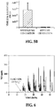
- the copper electrode was subsequently pulsed between +0.2 V and open circuit potential to turn NO generation on and off. The results are shown in Fig. 6 . As illustrated, after the source of nitrite was injected, NO was generated during the +0.2 V portion of the cycle.
- a silicone rubber tubing (2 cm length, 0.51 mm inner diameter, and 0.94 mm outer diameter) was sealed at one end with silicone rubber sealant.
- a 2 cm long polytetrafluoroethylene (PTFE)-coated silver/silver chloride wire was used as the reference electrode, and a 2 cm long PTFE-coated copper wire was used as the working electrode.
- the bare copper wire had an outer diameter of 0.127 mm, and coated copper wire had an outer diameter of 0.152 mm.
- the PTFE was removed from the ends of the silver/silver chloride wire and the copper wire in 20 mm and 10 mm lengths, respectively. The exposed ends of the respective wires were coiled separately. The coiled ends were inserted into the silicone rubber tubing so that the silver/silver chloride wire and the copper wire were not in direct metallic connection.
- a source of nitrite was loaded into the tubing.
- the source of nitrite included 1 M NaNO 2 , 0.138 M NaCl, 25 mM EDTA in 1 M phosphate buffered saline (PBS).
- PBS phosphate buffered saline
- the pH was adjusted to 7.2 with NaOH or using appropriate ratios of phosphate salts.
- the silicone rubber tubing was then sealed to form a catheter.
- PTFE-coated silver/silver chloride wire and PTFE-coated copper wire extended out of the silicone rubber tubing as respective leads to the reference and working electrodes.
- a cathodic voltage (-1.2 V vs. NHE) was applied to the working electrode for about 30 seconds, and then an anodic voltage (+0.2 V vs. NHE) was applied to the working electrode for about 30 seconds.
- the pulse sequence was performed over a 14 hour period. The pulse sequence was initiated for about 2 hours at hours 0, 7 and 12, and for about 5 hours from hour 3 to hour 8.
- the NO flux from the surface of the silicone rubber tubing is shown in Fig. 7 .
- the results shown in Fig. 7 illustrate that the potential applied to the copper coated electrode can be controlled to turn on or off the release of NO through the walls of the silicone rubber tubing.
- the silicone rubber tubing provided a barrier against the leaching of nitrite from the catheter, but also allowed for the electrochemically generated NO gas to readily diffuse out of the catheter.
- a bacterial biofilm dispersal study was performed using four NO generating catheters and one strain of bacteria, namely E .coli.
- a silicone rubber tubing (2 cm length, 0.51 mm inner diameter, and 0.94 mm outer diameter) was sealed at one end with silicone rubber sealant.
- a 2 cm long polytetrafluoroethylene (PTFE)-coated silver/silver chloride wire was used as the reference electrode, and a 2 cm long PTFE-coated copper wire was used as the working electrode.
- the bare silver/silver chloride wire had an outer diameter of 0.125 mm, and the coated silver/silver chloride wire had an outer diameter of 0.176 mm.
- the bare copper wire had an outer diameter of 0.127 mm, and the coated copper wire had an outer diameter of 0.152 mm.
- the PTFE was removed from the ends of the silver/silver chloride wire and the copper wire in 20 mm lengths to expose the bare electrodes.
- the exposed ends of the respective wires were coiled separately.
- the coiled ends were inserted into the silicone rubber tubing so that the silver/silver chloride wire and the copper wire were not in direct metallic connection.
- a source of nitrite was loaded into the tubing.
- the source of nitrite included 1 M NaNO 2 , 0.138 M NaCl, 0.02 M EDTA in 1 M phosphate buffered saline (PBS).
- PBS phosphate buffered saline
- the pH was adjusted to 6.8 with NaOH or using appropriate ratios of phosphate salts.
- PTFE-coated silver/silver chloride wire and PTFE-coated copper wire extended out of the silicone rubber tubing as respective leads to the reference and working electrodes.
- the experiment was performed over a 2 day period with continuous flow of media (80 mL/hr) using a drip-flow bioreactor.
- the catheters were immersed in the media containing E.coli.
- Two of the catheters were connected to a potentiostat and a pulse sequence was applied to the respective working electrodes for 3 hours after two days in the flowing media with the cells without generating NO.
- These catheters are referred to as the NO releasing catheters.
- One cycle of the pulse sequence included 30 seconds at -1.2 V vs. Ag/AgCl wire, and 30 seconds at +0.2 V vs. Ag/AgCl wire.
- These NO releasing catheters were able to generate an average NO flux of 1.2 * 10 -10 mol/cm 2 *min when this pulse sequence was applied.
- the other two catheters were used as controls. These control catheters contained the same nitrite salt solution and wires, but were not connected to potentiostats.
- one NO generating catheter and one control catheter were used for detection of viable bacteria on the catheter surfaces by a plate counting method.
- the other NO generating and control catheters were used for imaging.
- these two catheters were stained with fluorescent dyes (SYTO-9 and propidium iodide) for 20 minutes in the dark.
- the catheters were put on a glass slide before being observed with a fluorescence microscope equipped with Fluorescent Illumination System (X-cite 120, EXFO) and appropriate filter sets.
- Fig. 8A illustrates the results observed for the one control catheter and the one NO releasing catheter obtained by the fluorescence imaging of total bacteria on the respective surfaces. As shown in Fig. 8A , the fluorescent imaging experiments indicate a dramatic reduction in number of cells left on the surface for the NO releasing catheter.
- Fig. 8B illustrates the bacterium counting results (Colony Forming Units, CFU) after 2 days for the other control catheter and the other NO releasing catheter.
- the bacterium counting results ( Fig. 8B ) illustrate that NO generating catheters that were turned on for only 3 hours of NO release had nearly a 3 log unit reduction in the number of living E coli cells on their surface compared to the control.
- Both the fluorescence imaging and the bacterium counting results demonstrate the effectiveness of using the electrochemically modulated NO release catheter to disperse bacteria biofilm after they have formed on the surface.
- the results indicate the effectiveness using a one-time application of the NO release cycle for a relatively short period of time.
- a surface of a silicone rubber tubing (0.541 ⁇ m inner diameter, and 940 ⁇ m outer diameter) was modified by impregnating the tubing with tetradodecylammonium tetrakis (4-chlorophenyl) borate (ETH 500) and dioctyl sebacate (DOS) in an m-xylene solution. Impregnation was allowed to take place for 24 hours, and then the tubing was air-dried overnight inside of a fume-hood. The dried tubing was then put in an oven of 120°C for about 1 hour.
- ETH 500 tetradodecylammonium tetrakis (4-chlorophenyl) borate
- DOS dioctyl sebacate
- a source of nitrite was loaded into the tubing.
- the source of nitrite included 1 M NaNO 2 , 0.138 M NaCl, 20 mM EDTA in 1 M phosphate buffered saline (PBS).
- PBS phosphate buffered saline
- control catheter was the same type of surface modified catheter with the same source of nitrite and the same electrodes inserted inside the tubing, but the NO release was never electrochemically initiated.
- the catheter and control catheter put inside respective drift flow bioreactors to grow biofilm on the respective surfaces.
- a standard or double junction commercial Ag/AgCl reference electrode was also placed inside the same channel with the catheter, and with the control catheter. 10% live bacteria was then passed through the respective channels.
- the background open circuit potential (BOCP) was measured for 30 minutes vs. the respective external Ag/AgCl reference electrode.
- the chambers were then inoculated with E. Coli bacteria for one hour and then the media was flowed through continuously again.
- the open circuit potential (OCP) measurement against the external Ag/AgCl reference electrode was recorded every hour.
- the OCP was again measured every hour until the next event (i.e., a change in OCP) was observed. This indicated that bacteria were again starting to stick on the catheter surface.
- the electrochemical pulse was again turned on to release NO for 2 hours.
- the NO flux used for the second NO release was 0.5 X 10 -10 moles/cm 2 .min.
- the electrochemical pulse used was -1.2V for 30 seconds and +0.1 for 30 seconds.
- the catheter and the control catheter were taken out of the respective chambers and the surface bacteria were dispersed into respective solutions via a homogenizer.
- the solutions were plate counted to determine the number of live bacteria left on the catheter surface and the control catheter surface.
- the number of bacteria after the experiment with the catheter was found to be 36% less than the control.
- Example catheters S1-S5 and four control catheters (C1-C4) were prepared to assess the in vivo effects of electrochemical release of NO on thrombus formation. All of the example catheters and the control catheters were prepared as previously described in Example 4, except an additional length (about 3 inches) of inert tubing was attached to the top end to enable insertion of the distal tips into rabbit veins.
- Example catheters S1, S3, S4 and S5 and control catheters C1-C4 were implanted in rabbit jugular veins and allowed to remain in the veins for 6 hours.
- Example catheter S2 was implanted into a rabbit leg vein and was allowed to remain for 6 hours.
- an electrochemical pulse sequence was turned on, with the NO flux ranging from 0.8*10 -10 moles/cm 2 .min to 1.1*10 -10 moles/cm 2 .min to release NO.
- the particular NO flux at 37°C for the respective Example catheters is shown in Table 1.
- the electrochemical pulse sequence was turned off, with the NO flux ⁇ 0.3*10 -10 moles/cm 2 .min.
- Table 1 Sample or Control NO flux@ 37°C Thrombus Area/cm 2 Total Area/cm 2 Surface Coverage S1 ⁇ 1.1*10 -10 moles/cm 2 .min 0.021 0.315 6.7% S2 ⁇ 1.0*10 -10 moles/cm 2 .min 0.010 0.202 5.0% S3 ⁇ 1.1*10 -10 moles/cm 2 .min 0.039 0.202 19.3% S4 ⁇ 0.8*10 -10 moles/cm 2 .min 0.078 0.167 46.7% S5 ⁇ 0.9*10 -10 moles/cm 2 .min 0.083 0.252 46.7% AVG.
- each of the example catheters had less thrombus formation than each of the control catheters. For those example catheters when the NO flux was lower, there was a bit more thrombus formation. Overall, these results illustrate that in vivo electrochemical generation of NO reduces thrombus formation.
- nitric oxide gas can be efficiently generated from nitrite using electrodes and the two-step voltage cycle disclosed herein.
- the reductive cleaning of the electrode prepares the electrode for anodic liberation of Cu(I) ions, which react with nitrite to generate NO. It is believed that this process can be employed to modulate the release of NO from polymer surfaces used to prepare, for example, in-dwelling catheters. Since continuous fluxes of NO to kill or disperse biofilm forming on microbes or to prevent platelet induced clotting may not be necessary, it is believed that catheters and other medical devices disclosed herein may be utilized effectively for longer periods of time with a given supply of nitrite.
- ranges provided herein include the stated range and any value or sub-range within the stated range.
- a range from about 1 cm to about 2 cm should be interpreted to include not only the explicitly recited limits of about 1 cm to about 2 cm, but also to include individual values, such as 1.5 cm, 1.75 cm, etc., and sub-ranges, such as from about 1.25 cm to about 1.75 cm, etc.
- “about” is utilized to describe a value, this is meant to encompass minor variations (up to +/- 5%) from the stated value.
- applied potential values are discussed, it is to be understood that wider ranges may be suitable.
- Increasing the magnitude of the anodic potential pulse increases the amount of Cu(I), and thus also increases the amount of NO generated.
- a broad range is applicable for the applied potential values, the limits of which may depend on the desired amount of Cu(I) and NO to be generated, or on the time required to clean the working electrode.
Landscapes
- Health & Medical Sciences (AREA)
- Chemical & Material Sciences (AREA)
- Life Sciences & Earth Sciences (AREA)
- Veterinary Medicine (AREA)
- General Health & Medical Sciences (AREA)
- Animal Behavior & Ethology (AREA)
- Public Health (AREA)
- Engineering & Computer Science (AREA)
- Organic Chemistry (AREA)
- Inorganic Chemistry (AREA)
- Hematology (AREA)
- Anesthesiology (AREA)
- Biomedical Technology (AREA)
- Heart & Thoracic Surgery (AREA)
- Pulmonology (AREA)
- Biophysics (AREA)
- Epidemiology (AREA)
- Pharmacology & Pharmacy (AREA)
- Medicinal Chemistry (AREA)
- Metallurgy (AREA)
- Materials Engineering (AREA)
- Electrochemistry (AREA)
- Chemical Kinetics & Catalysis (AREA)
- Vascular Medicine (AREA)
- Materials For Medical Uses (AREA)
Claims (15)
- Dispositif d'administration d'oxyde nitrique (10), comprenant :un boîtier qui est perméable à l'oxyde nitrique ;une électrode de travail (12) à l'intérieur du boîtier, l'électrode de travail étant un matériau conducteur contenant du cuivre qui produit une faible concentration d'ions Cu(I) à une surface de l'électrode de travail en réponse à une impulsion de tension anodique appliquée à celle-ci ;un fil conducteur (16) relié électriquement à l'électrode de travail et s'étendant à l'extérieur du boîtier ;l'une quelconque parmi une électrode de référence (14) ou une contre-électrode à l'intérieur du boîtier et isolée électriquement de l'électrode de travail ;un second fil conducteur (18) relié électriquement à l'une quelconque parmi l'électrode de référence ou la contre-électrode et s'étendant à l'extérieur du boîtier ; etune source d'ions nitrite (26) devant être contenue à l'intérieur du boîtier et en contact avec l'électrode de travail, la source d'ions nitrite étant choisie parmi le groupe constitué d'un sel nitrite inorganique, soluble dans l'eau, dans une solution aqueuse ou un hydrogel et une espèce nitrite d'ammonium quaternaire lipophile dans une phase polymère organique ;le nitrite dans la source d'ions nitrite étant réduit par les ions Cu(I) pour générer de l'oxyde nitrique.
- Dispositif d'administration d'oxyde nitrique selon la revendication 1, dans lequel le dispositif d'administration est un cathéter à lumière unique ou un cathéter à lumières multiples (100).
- Dispositif d'administration d'oxyde nitrique selon la revendication 2, dans lequel :le fil conducteur a un revêtement polymère sur celui-ci ;un autre revêtement polymère est établi i) sur le second fil conducteur de telle sorte qu'une extrémité du second fil conducteur reste exposée, et ii) sur une zone de l'une quelconque parmi l'électrode de référence ou la contre-électrode qui est adjacente à l'électrode de travail ; etune autre zone de l'une quelconque parmi l'électrode de référence ou la contre-électrode reste exposée et, de préférence, l'électrode de travail et celle quelconque parmi l'électrode de référence ou la contre-électrode étant scellées de manière étanche à l'intérieur du boîtier.
- Dispositif d'administration d'oxyde nitrique selon la revendication 1, dans lequel le dispositif d'administration est un timbre plat (100').
- Dispositif d'administration d'oxyde nitrique selon la revendication 4, dans lequel :l'électrode de travail est un treillis (12') ;le fil conducteur est un fil conducteur relié électriquement au treillis ;celle quelconque parmi l'électrode de référence ou la contre-électrode est un treillis contenant du métal ;le second fil conducteur est un fil conducteur relié électriquement au treillis contenant du métal ; etle dispositif d'administration comprend en outre un séparateur à conduction ionique, à isolation électrique (44) positionné entre le treillis et le treillis contenant du métal et, de préférence, le treillis et le treillis contenant du métal étant scellés de manière étanche à l'intérieur du boîtier, ou l'électrode de travail comprenant des particules de cuivre ou d'alliage de cuivre intégrées dans une matrice polymère.
- Dispositif d'administration d'oxyde nitrique selon la revendication 1, comprenant en outre une circuiterie (20) pour relier électriquement l'électrode de travail et celle quelconque parmi l'électrode de référence ou la contre-électrode de façon à appliquer de manière sélective l'impulsion de tension anodique à l'électrode de travail par rapport à celle quelconque parmi l'électrode de référence ou la contre-électrode.
- Dispositif d'administration d'oxyde nitrique selon la revendication 1, dans lequel le boîtier est formé d'un matériau choisi parmi le caoutchouc de silicone, le polyuréthane de qualité biomédicale, le polytétrafluoroéthylène, des dérivés de polytétrafluoroéthylène, le poly(chlorure de vinyle) et le polyméthacrylate.
- Dispositif d'administration d'oxyde nitrique selon la revendication 1, dans lequel la source d'ions nitrite est un sel nitrite d'ammonium quaternaire lipophile dans une phase polymère organique, et le sel nitrite d'ammonium quaternaire lipophile étant choisi parmi le nitrite de tétradodécylammonium, le nitrite de tridodécylméthylammonium, le nitrite de tétradécylammonium et le nitrite de tétraoctylammonium ; et la phase polymère organique étant choisie parmi le polyuréthane, le poly(chlorure de vinyle), le polyméthacrylate et le polydiméthylsiloxane et, de préférence, l'électrode de travail étant une pluralité de nanoparticules de cuivre ou d'alliage de cuivre dans la phase polymère organique.
- Dispositif d'administration d'oxyde nitrique selon la revendication 1, dans lequel l'électrode de travail est une encre imprimée du matériau conducteur contenant du cuivre.
- Procédé pour générer de l'oxyde nitrique, comprenant :appliquer une tension cathodique à une électrode de travail (12) à l'intérieur d'un boîtier polymère par l'intermédiaire d'un fil conducteur (16) qui s'étend à l'extérieur du boîtier polymère, le boîtier polymère contenant une source d'ions nitrite (26) qui est en contact avec l'électrode de travail, la source d'ions nitrite étant choisie parmi le groupe constitué d'un sel nitrite inorganique, soluble dans l'eau, dans une solution aqueuse ou un hydrogel et une espèce nitrite d'ammonium quaternaire lipophile dans une phase polymère organique, et l'électrode de travail étant un matériau conducteur contenant du cuivre ; etappliquer une tension anodique à l'électrode de travail, produisant ainsi localement des ions Cu(I) à une surface de l'électrode de travail qui réagissent avec et réduisent le nitrite provenant de la source d'ions nitrite pour former de l'oxyde nitrique gazeux et, de préférence, l'application de la tension cathodique à l'électrode de travail étant réalisée pendant une durée prédéterminée allant d'environ 1 seconde à environ 10 minutes.
- Procédé selon la revendication 10, dans lequel l'application de la tension anodique à l'électrode de travail pendant une durée prédéterminée amène l'électrode de travail à devenir passivée, et le procédé comprenant en outre appliquer une autre tension cathodique à l'électrode de travail pour nettoyer l'électrode de travail et, de préférence, après que l'électrode de travail est nettoyée, le procédé comprenant en outre appliquer une autre tension anodique à l'électrode de travail, produisant ainsi à nouveau localement des ions Cu(I) à la surface de l'électrode de travail qui réagissent avec et réduisent le nitrite provenant de la source d'ions nitrite pour former de l'oxyde nitrique gazeux.
- Procédé selon la revendication 10, dans lequel le boîtier est formé d'un matériau qui est perméable à l'oxyde nitrique gazeux, et le procédé comprenant en outre commander la libération d'oxyde nitrique gazeux par commande de lorsque les tensions sont appliquées à l'électrode de travail.
- Procédé selon la revendication 10, comprenant en outre moduler un flux d'oxyde nitrique qui est généré par l'un quelconque parmi modifier une valeur d'une aire de surface de l'électrode de travail qui est exposée à la source d'ions nitrite ou modifier une concentration nitrite dans la source d'ions nitrite.
- Dispositif d'administration d'oxyde nitrique selon la revendication 1, dans lequel le sel nitrite inorganique soluble dans l'eau est choisi parmi des sels nitrite de Li, Na, K, Rb, Ca et Mg.
- Dispositif d'administration d'oxyde nitrique selon la revendication 1, dans lequel la tension anodique est un potentiel positif par rapport à une électrode standard à hydrogène (NHE) ou une électrode de référence Ag/AgCl.
Applications Claiming Priority (2)
| Application Number | Priority Date | Filing Date | Title |
|---|---|---|---|
| US201261617886P | 2012-03-30 | 2012-03-30 | |
| PCT/US2013/034425 WO2013149044A1 (fr) | 2012-03-30 | 2013-03-28 | Dispositif d'administration d'oxyde nitrique |
Publications (3)
| Publication Number | Publication Date |
|---|---|
| EP2830698A1 EP2830698A1 (fr) | 2015-02-04 |
| EP2830698A4 EP2830698A4 (fr) | 2015-12-09 |
| EP2830698B1 true EP2830698B1 (fr) | 2019-03-13 |
Family
ID=49235966
Family Applications (1)
| Application Number | Title | Priority Date | Filing Date |
|---|---|---|---|
| EP13769256.2A Active EP2830698B1 (fr) | 2012-03-30 | 2013-03-28 | Dispositif d'administration d'oxyde nitrique |
Country Status (4)
| Country | Link |
|---|---|
| US (2) | US9872953B2 (fr) |
| EP (1) | EP2830698B1 (fr) |
| CN (1) | CN104394923B (fr) |
| WO (1) | WO2013149044A1 (fr) |
Families Citing this family (10)
| Publication number | Priority date | Publication date | Assignee | Title |
|---|---|---|---|---|
| US9480785B2 (en) | 2012-03-30 | 2016-11-01 | The Regents Of The University Of Michigan | Nitric oxide delivery devices |
| US10449321B2 (en) * | 2012-03-30 | 2019-10-22 | The Regents Of The University Of Michigan | Gas delivery devices |
| CN106669021B (zh) * | 2016-12-13 | 2019-07-30 | 东南大学 | 一种细菌生物膜处理装置 |
| JP6989157B2 (ja) * | 2017-02-09 | 2022-01-05 | ノクサノ インコーポレイテッド | 電気化学ガス状伝達物質生成組成物及びその使用方法ならびにそれを組み込んだ被覆材及び治療システム |
| EP4706724A2 (fr) * | 2017-04-11 | 2026-03-11 | The Regents Of The University Of Michigan | Dispositifs de distribution de gaz |
| CN111601626B (zh) * | 2017-09-02 | 2022-05-06 | 生物克瑞德公司 | 具有集成的生物传感器的医疗装置 |
| CN110873810B (zh) * | 2018-08-31 | 2025-04-29 | 科美诊断技术股份有限公司 | 全自动化学发光分析仪的轨道进样系统 |
| CN118846318A (zh) * | 2018-09-27 | 2024-10-29 | 密歇根大学董事会 | 气体输送装置 |
| US11872367B2 (en) | 2020-01-02 | 2024-01-16 | Becton, Dickinson And Company | Antimicrobial and antithrombogenic gaseous release device and related systems and methods |
| US11813059B2 (en) | 2021-11-30 | 2023-11-14 | Zense-Life Inc. | Sensor for a continuous biological monitor having nitric oxide releasing compound |
Family Cites Families (16)
| Publication number | Priority date | Publication date | Assignee | Title |
|---|---|---|---|---|
| US3726777A (en) * | 1970-04-30 | 1973-04-10 | Gen Electric | Iridium-iridium oxide electrode for measuring ph of blood and other fluids |
| US4834101A (en) | 1987-06-26 | 1989-05-30 | The University Of Michigan | Catheter-type electrochemical sensors |
| US5396882A (en) | 1992-03-11 | 1995-03-14 | The General Hospital Corporation | Generation of nitric oxide from air for medical uses |
| BR9303645A (pt) | 1993-08-31 | 1995-04-25 | Oliveira Marques Antonio Se De | Processo de fabricação de produto alimentício |
| JPH09502690A (ja) | 1993-09-13 | 1997-03-18 | アーゲーアー アクツイエボラーグ | 酸化窒素を製造する方法及び装置 |
| US5827420A (en) * | 1997-07-29 | 1998-10-27 | World Precision Instruments, Inc. | Method and apparatus for the generation of nitric oxide |
| US6097976A (en) * | 1998-02-27 | 2000-08-01 | Ep Technologies, Inc. | Catheter distal end assemblies with bonded surface coatings |
| US7335383B2 (en) * | 2001-01-16 | 2008-02-26 | The Regents Of The University Of Michigan | Generation of nitric oxide in vivo from nitrite, nitrate or nitrosothiols endogenous in blood |
| EP1395241B9 (fr) * | 2001-05-25 | 2005-06-15 | Medtronic, Inc. | Dispositif medical implantable equipe d'un systeme de liberation controlee d'agents gazeux |
| EP1429829B1 (fr) | 2001-09-05 | 2013-11-27 | Geno LLC | Generation d'oxyde nitrique |
| US7407570B2 (en) * | 2002-03-13 | 2008-08-05 | The Charles Stark Draper Laboratory, Inc. | Disposable, self-administered electrolyte test |
| US20060008529A1 (en) * | 2004-07-12 | 2006-01-12 | Meyerhoff Mark E | Use of additive sites to control nitric oxide release from nitric oxide donors contained within polymers |
| WO2007005759A2 (fr) * | 2005-06-30 | 2007-01-11 | Mc3, Inc. | Sondes a analysats et compositions a cet effet |
| JP2009518069A (ja) * | 2005-12-02 | 2009-05-07 | ザ・リージェンツ・オブ・ザ・ユニバーシティ・オブ・ミシガン | 組成物、コーティング及びデバイス、並びにそれらの製造方法及び使用方法 |
| US7809441B2 (en) * | 2006-05-17 | 2010-10-05 | Cardiac Pacemakers, Inc. | Implantable medical device with chemical sensor and related methods |
| US8551322B2 (en) * | 2006-08-24 | 2013-10-08 | University Of North Carolina At Chapel Hill | Nitric oxide microsensors via fluorosilane-based xerogel membranes |
-
2013
- 2013-03-28 EP EP13769256.2A patent/EP2830698B1/fr active Active
- 2013-03-28 US US14/388,482 patent/US9872953B2/en active Active
- 2013-03-28 WO PCT/US2013/034425 patent/WO2013149044A1/fr not_active Ceased
- 2013-03-28 US US13/852,841 patent/US9498571B2/en active Active
- 2013-03-28 CN CN201380028171.9A patent/CN104394923B/zh active Active
Non-Patent Citations (1)
| Title |
|---|
| None * |
Also Published As
| Publication number | Publication date |
|---|---|
| CN104394923A (zh) | 2015-03-04 |
| US20130261537A1 (en) | 2013-10-03 |
| US9498571B2 (en) | 2016-11-22 |
| EP2830698A4 (fr) | 2015-12-09 |
| CN104394923B (zh) | 2017-07-14 |
| EP2830698A1 (fr) | 2015-02-04 |
| US9872953B2 (en) | 2018-01-23 |
| US20150073331A1 (en) | 2015-03-12 |
| WO2013149044A1 (fr) | 2013-10-03 |
Similar Documents
| Publication | Publication Date | Title |
|---|---|---|
| EP2830698B1 (fr) | Dispositif d'administration d'oxyde nitrique | |
| US11413420B2 (en) | Nitric oxide delivery devices | |
| AU2012272993B2 (en) | Electrochemical disinfection of implanted catheters | |
| JP7361421B2 (ja) | ガス供給方法 | |
| JP3555684B2 (ja) | 医療装置用電気泳動構造物 | |
| JP3368322B2 (ja) | 制御イオン導入方法および装置 | |
| US10449321B2 (en) | Gas delivery devices | |
| EP1221980B1 (fr) | Production electrolytique d'iode naissant pour le traitement et la prevention d'infections associees aux protheses medicales | |
| Höfler et al. | Electromodulated release of nitric oxide through polymer material from reservoir of inorganic nitrite salt | |
| CN121693352A (zh) | 杀菌系统和杀菌方法 | |
| Novak et al. | Portable Bluetooth Microsystem for Electrochemically Modulated Nitric Oxide-Releasing Catheters |
Legal Events
| Date | Code | Title | Description |
|---|---|---|---|
| PUAI | Public reference made under article 153(3) epc to a published international application that has entered the european phase |
Free format text: ORIGINAL CODE: 0009012 |
|
| 17P | Request for examination filed |
Effective date: 20141022 |
|
| AK | Designated contracting states |
Kind code of ref document: A1 Designated state(s): AL AT BE BG CH CY CZ DE DK EE ES FI FR GB GR HR HU IE IS IT LI LT LU LV MC MK MT NL NO PL PT RO RS SE SI SK SM TR |
|
| AX | Request for extension of the european patent |
Extension state: BA ME |
|
| RIN1 | Information on inventor provided before grant (corrected) |
Inventor name: MEYERHOFF, MARK, E. Inventor name: HOFLER, LAJOS Inventor name: KOLEY, DIPANKAR |
|
| DAX | Request for extension of the european patent (deleted) | ||
| RA4 | Supplementary search report drawn up and despatched (corrected) |
Effective date: 20151111 |
|
| RIC1 | Information provided on ipc code assigned before grant |
Ipc: A61M 25/00 20060101ALI20151105BHEP Ipc: A61K 33/00 20060101ALI20151105BHEP Ipc: C01B 21/24 20060101AFI20151105BHEP |
|
| REG | Reference to a national code |
Ref country code: DE Ref legal event code: R079 Ref document number: 602013052322 Country of ref document: DE Free format text: PREVIOUS MAIN CLASS: A61M0031000000 Ipc: A61M0025000000 |
|
| RIC1 | Information provided on ipc code assigned before grant |
Ipc: C01B 21/24 20060101ALI20180802BHEP Ipc: A61M 25/00 20060101AFI20180802BHEP Ipc: A61M 5/14 20060101ALI20180802BHEP Ipc: A61K 33/00 20060101ALI20180802BHEP |
|
| GRAP | Despatch of communication of intention to grant a patent |
Free format text: ORIGINAL CODE: EPIDOSNIGR1 |
|
| STAA | Information on the status of an ep patent application or granted ep patent |
Free format text: STATUS: GRANT OF PATENT IS INTENDED |
|
| INTG | Intention to grant announced |
Effective date: 20180924 |
|
| GRAS | Grant fee paid |
Free format text: ORIGINAL CODE: EPIDOSNIGR3 |
|
| GRAA | (expected) grant |
Free format text: ORIGINAL CODE: 0009210 |
|
| STAA | Information on the status of an ep patent application or granted ep patent |
Free format text: STATUS: THE PATENT HAS BEEN GRANTED |
|
| AK | Designated contracting states |
Kind code of ref document: B1 Designated state(s): AL AT BE BG CH CY CZ DE DK EE ES FI FR GB GR HR HU IE IS IT LI LT LU LV MC MK MT NL NO PL PT RO RS SE SI SK SM TR |
|
| REG | Reference to a national code |
Ref country code: GB Ref legal event code: FG4D |
|
| REG | Reference to a national code |
Ref country code: CH Ref legal event code: EP Ref country code: AT Ref legal event code: REF Ref document number: 1106853 Country of ref document: AT Kind code of ref document: T Effective date: 20190315 |
|
| REG | Reference to a national code |
Ref country code: IE Ref legal event code: FG4D |
|
| REG | Reference to a national code |
Ref country code: DE Ref legal event code: R096 Ref document number: 602013052322 Country of ref document: DE |
|
| REG | Reference to a national code |
Ref country code: NL Ref legal event code: MP Effective date: 20190313 |
|
| REG | Reference to a national code |
Ref country code: LT Ref legal event code: MG4D |
|
| PG25 | Lapsed in a contracting state [announced via postgrant information from national office to epo] |
Ref country code: FI Free format text: LAPSE BECAUSE OF FAILURE TO SUBMIT A TRANSLATION OF THE DESCRIPTION OR TO PAY THE FEE WITHIN THE PRESCRIBED TIME-LIMIT Effective date: 20190313 Ref country code: LT Free format text: LAPSE BECAUSE OF FAILURE TO SUBMIT A TRANSLATION OF THE DESCRIPTION OR TO PAY THE FEE WITHIN THE PRESCRIBED TIME-LIMIT Effective date: 20190313 Ref country code: SE Free format text: LAPSE BECAUSE OF FAILURE TO SUBMIT A TRANSLATION OF THE DESCRIPTION OR TO PAY THE FEE WITHIN THE PRESCRIBED TIME-LIMIT Effective date: 20190313 Ref country code: NO Free format text: LAPSE BECAUSE OF FAILURE TO SUBMIT A TRANSLATION OF THE DESCRIPTION OR TO PAY THE FEE WITHIN THE PRESCRIBED TIME-LIMIT Effective date: 20190613 |
|
| PG25 | Lapsed in a contracting state [announced via postgrant information from national office to epo] |
Ref country code: LV Free format text: LAPSE BECAUSE OF FAILURE TO SUBMIT A TRANSLATION OF THE DESCRIPTION OR TO PAY THE FEE WITHIN THE PRESCRIBED TIME-LIMIT Effective date: 20190313 Ref country code: RS Free format text: LAPSE BECAUSE OF FAILURE TO SUBMIT A TRANSLATION OF THE DESCRIPTION OR TO PAY THE FEE WITHIN THE PRESCRIBED TIME-LIMIT Effective date: 20190313 Ref country code: HR Free format text: LAPSE BECAUSE OF FAILURE TO SUBMIT A TRANSLATION OF THE DESCRIPTION OR TO PAY THE FEE WITHIN THE PRESCRIBED TIME-LIMIT Effective date: 20190313 Ref country code: GR Free format text: LAPSE BECAUSE OF FAILURE TO SUBMIT A TRANSLATION OF THE DESCRIPTION OR TO PAY THE FEE WITHIN THE PRESCRIBED TIME-LIMIT Effective date: 20190614 Ref country code: BG Free format text: LAPSE BECAUSE OF FAILURE TO SUBMIT A TRANSLATION OF THE DESCRIPTION OR TO PAY THE FEE WITHIN THE PRESCRIBED TIME-LIMIT Effective date: 20190613 Ref country code: NL Free format text: LAPSE BECAUSE OF FAILURE TO SUBMIT A TRANSLATION OF THE DESCRIPTION OR TO PAY THE FEE WITHIN THE PRESCRIBED TIME-LIMIT Effective date: 20190313 |
|
| REG | Reference to a national code |
Ref country code: AT Ref legal event code: MK05 Ref document number: 1106853 Country of ref document: AT Kind code of ref document: T Effective date: 20190313 |
|
| PG25 | Lapsed in a contracting state [announced via postgrant information from national office to epo] |
Ref country code: EE Free format text: LAPSE BECAUSE OF FAILURE TO SUBMIT A TRANSLATION OF THE DESCRIPTION OR TO PAY THE FEE WITHIN THE PRESCRIBED TIME-LIMIT Effective date: 20190313 Ref country code: ES Free format text: LAPSE BECAUSE OF FAILURE TO SUBMIT A TRANSLATION OF THE DESCRIPTION OR TO PAY THE FEE WITHIN THE PRESCRIBED TIME-LIMIT Effective date: 20190313 Ref country code: CZ Free format text: LAPSE BECAUSE OF FAILURE TO SUBMIT A TRANSLATION OF THE DESCRIPTION OR TO PAY THE FEE WITHIN THE PRESCRIBED TIME-LIMIT Effective date: 20190313 Ref country code: RO Free format text: LAPSE BECAUSE OF FAILURE TO SUBMIT A TRANSLATION OF THE DESCRIPTION OR TO PAY THE FEE WITHIN THE PRESCRIBED TIME-LIMIT Effective date: 20190313 Ref country code: SK Free format text: LAPSE BECAUSE OF FAILURE TO SUBMIT A TRANSLATION OF THE DESCRIPTION OR TO PAY THE FEE WITHIN THE PRESCRIBED TIME-LIMIT Effective date: 20190313 Ref country code: PT Free format text: LAPSE BECAUSE OF FAILURE TO SUBMIT A TRANSLATION OF THE DESCRIPTION OR TO PAY THE FEE WITHIN THE PRESCRIBED TIME-LIMIT Effective date: 20190713 Ref country code: AL Free format text: LAPSE BECAUSE OF FAILURE TO SUBMIT A TRANSLATION OF THE DESCRIPTION OR TO PAY THE FEE WITHIN THE PRESCRIBED TIME-LIMIT Effective date: 20190313 Ref country code: IT Free format text: LAPSE BECAUSE OF FAILURE TO SUBMIT A TRANSLATION OF THE DESCRIPTION OR TO PAY THE FEE WITHIN THE PRESCRIBED TIME-LIMIT Effective date: 20190313 |
|
| REG | Reference to a national code |
Ref country code: CH Ref legal event code: PL |
|
| PG25 | Lapsed in a contracting state [announced via postgrant information from national office to epo] |
Ref country code: LU Free format text: LAPSE BECAUSE OF NON-PAYMENT OF DUE FEES Effective date: 20190328 Ref country code: SM Free format text: LAPSE BECAUSE OF FAILURE TO SUBMIT A TRANSLATION OF THE DESCRIPTION OR TO PAY THE FEE WITHIN THE PRESCRIBED TIME-LIMIT Effective date: 20190313 Ref country code: PL Free format text: LAPSE BECAUSE OF FAILURE TO SUBMIT A TRANSLATION OF THE DESCRIPTION OR TO PAY THE FEE WITHIN THE PRESCRIBED TIME-LIMIT Effective date: 20190313 |
|
| REG | Reference to a national code |
Ref country code: BE Ref legal event code: MM Effective date: 20190331 |
|
| REG | Reference to a national code |
Ref country code: DE Ref legal event code: R097 Ref document number: 602013052322 Country of ref document: DE |
|
| PG25 | Lapsed in a contracting state [announced via postgrant information from national office to epo] |
Ref country code: IS Free format text: LAPSE BECAUSE OF FAILURE TO SUBMIT A TRANSLATION OF THE DESCRIPTION OR TO PAY THE FEE WITHIN THE PRESCRIBED TIME-LIMIT Effective date: 20190713 Ref country code: AT Free format text: LAPSE BECAUSE OF FAILURE TO SUBMIT A TRANSLATION OF THE DESCRIPTION OR TO PAY THE FEE WITHIN THE PRESCRIBED TIME-LIMIT Effective date: 20190313 |
|
| PLBE | No opposition filed within time limit |
Free format text: ORIGINAL CODE: 0009261 |
|
| STAA | Information on the status of an ep patent application or granted ep patent |
Free format text: STATUS: NO OPPOSITION FILED WITHIN TIME LIMIT |
|
| PG25 | Lapsed in a contracting state [announced via postgrant information from national office to epo] |
Ref country code: DK Free format text: LAPSE BECAUSE OF FAILURE TO SUBMIT A TRANSLATION OF THE DESCRIPTION OR TO PAY THE FEE WITHIN THE PRESCRIBED TIME-LIMIT Effective date: 20190313 Ref country code: IE Free format text: LAPSE BECAUSE OF NON-PAYMENT OF DUE FEES Effective date: 20190328 Ref country code: MC Free format text: LAPSE BECAUSE OF FAILURE TO SUBMIT A TRANSLATION OF THE DESCRIPTION OR TO PAY THE FEE WITHIN THE PRESCRIBED TIME-LIMIT Effective date: 20190313 Ref country code: CH Free format text: LAPSE BECAUSE OF NON-PAYMENT OF DUE FEES Effective date: 20190331 Ref country code: LI Free format text: LAPSE BECAUSE OF NON-PAYMENT OF DUE FEES Effective date: 20190331 |
|
| 26N | No opposition filed |
Effective date: 20191216 |
|
| PG25 | Lapsed in a contracting state [announced via postgrant information from national office to epo] |
Ref country code: SI Free format text: LAPSE BECAUSE OF FAILURE TO SUBMIT A TRANSLATION OF THE DESCRIPTION OR TO PAY THE FEE WITHIN THE PRESCRIBED TIME-LIMIT Effective date: 20190313 Ref country code: BE Free format text: LAPSE BECAUSE OF NON-PAYMENT OF DUE FEES Effective date: 20190331 |
|
| PG25 | Lapsed in a contracting state [announced via postgrant information from national office to epo] |
Ref country code: TR Free format text: LAPSE BECAUSE OF FAILURE TO SUBMIT A TRANSLATION OF THE DESCRIPTION OR TO PAY THE FEE WITHIN THE PRESCRIBED TIME-LIMIT Effective date: 20190313 |
|
| PG25 | Lapsed in a contracting state [announced via postgrant information from national office to epo] |
Ref country code: MT Free format text: LAPSE BECAUSE OF NON-PAYMENT OF DUE FEES Effective date: 20190328 |
|
| PG25 | Lapsed in a contracting state [announced via postgrant information from national office to epo] |
Ref country code: CY Free format text: LAPSE BECAUSE OF FAILURE TO SUBMIT A TRANSLATION OF THE DESCRIPTION OR TO PAY THE FEE WITHIN THE PRESCRIBED TIME-LIMIT Effective date: 20190313 |
|
| PG25 | Lapsed in a contracting state [announced via postgrant information from national office to epo] |
Ref country code: HU Free format text: LAPSE BECAUSE OF FAILURE TO SUBMIT A TRANSLATION OF THE DESCRIPTION OR TO PAY THE FEE WITHIN THE PRESCRIBED TIME-LIMIT; INVALID AB INITIO Effective date: 20130328 |
|
| PG25 | Lapsed in a contracting state [announced via postgrant information from national office to epo] |
Ref country code: MK Free format text: LAPSE BECAUSE OF FAILURE TO SUBMIT A TRANSLATION OF THE DESCRIPTION OR TO PAY THE FEE WITHIN THE PRESCRIBED TIME-LIMIT Effective date: 20190313 |
|
| P01 | Opt-out of the competence of the unified patent court (upc) registered |
Effective date: 20230510 |
|
| PGFP | Annual fee paid to national office [announced via postgrant information from national office to epo] |
Ref country code: GB Payment date: 20260325 Year of fee payment: 14 |
|
| PGFP | Annual fee paid to national office [announced via postgrant information from national office to epo] |
Ref country code: DE Payment date: 20260320 Year of fee payment: 14 |
|
| PGFP | Annual fee paid to national office [announced via postgrant information from national office to epo] |
Ref country code: FR Payment date: 20260324 Year of fee payment: 14 |