EP2830729B1 - Toboggan de loisir et de jeu - Google Patents
Toboggan de loisir et de jeu Download PDFInfo
- Publication number
- EP2830729B1 EP2830729B1 EP13713830.1A EP13713830A EP2830729B1 EP 2830729 B1 EP2830729 B1 EP 2830729B1 EP 13713830 A EP13713830 A EP 13713830A EP 2830729 B1 EP2830729 B1 EP 2830729B1
- Authority
- EP
- European Patent Office
- Prior art keywords
- sliding
- amusement
- trail
- slide according
- tube
- Prior art date
- Legal status (The legal status is an assumption and is not a legal conclusion. Google has not performed a legal analysis and makes no representation as to the accuracy of the status listed.)
- Active
Links
Images



Classifications
-
- A—HUMAN NECESSITIES
- A63—SPORTS; GAMES; AMUSEMENTS
- A63G—MERRY-GO-ROUNDS; SWINGS; ROCKING-HORSES; CHUTES; SWITCHBACKS; SIMILAR DEVICES FOR PUBLIC AMUSEMENT
- A63G21/00—Chutes; Helter-skelters
- A63G21/14—Chutes; Helter-skelters with driven slideways
-
- A—HUMAN NECESSITIES
- A63—SPORTS; GAMES; AMUSEMENTS
- A63G—MERRY-GO-ROUNDS; SWINGS; ROCKING-HORSES; CHUTES; SWITCHBACKS; SIMILAR DEVICES FOR PUBLIC AMUSEMENT
- A63G21/00—Chutes; Helter-skelters
- A63G21/10—Chutes; Helter-skelters with spiral tracks
-
- A—HUMAN NECESSITIES
- A63—SPORTS; GAMES; AMUSEMENTS
- A63G—MERRY-GO-ROUNDS; SWINGS; ROCKING-HORSES; CHUTES; SWITCHBACKS; SIMILAR DEVICES FOR PUBLIC AMUSEMENT
- A63G21/00—Chutes; Helter-skelters
- A63G21/18—Water-chutes
Definitions
- the present invention relates to an amusement and leisure slide for attraction parks, hotels, business or shopping centers with various combinations of thrilling experiences.
- the slide comprises one or several toboggan curved tubes in which a rider slides on a variable slope in a wet or dry environment.
- Some conventional slides comprise static curved tubes and take a significantly large space and height to provide a sufficiently long path having a constant or variable downward slope.
- a waterslide apparatus comprising a bowl having a curved sidewall; and two or more rider entrances for enabling riders to slide into the bowl and to circuit at least a portion of the bowl.
- the waterslide apparatus allows two or more riders to circuit at least a portion of the bowl at the same time.
- the rider entrances may be provided at different heights in the sidewall of the bowl.
- a chute or flume is preferably associated with each rider entrance. In use, the riders travel down the chute or flume and enter the bowl with sufficient momentum to travel at least partway around the bowl.
- the chutes each have an inlet through which a rider enters and an outlet which mates with the rider entrance.
- the chutes each have a longitudinal axis which proximal the inlet is inclined at an angle of less than or equal to 30° measured relative to the vertical.
- Document WO2009141588A2 discloses a system for conveying an individual in a leisure park, the system comprises a tube having an inlet and an outlet; and a rotatable screw for conveying the individual from said inlet to said outlet.
- the system further comprises an inlet flow control means adapted operatively to cause a surge of water into said inlet suitable for biasing an individual into the tube; and/or an outlet flow control means adapted operatively to cause a surge of water out of said outlet for biasing an individual out of the tube.
- the surge of water may correspond to an increased flow rate of the water as it enters the inlet and/or exits the outlet.
- the surge of water is sufficient to transport the individual into the inlet and/or out of the outlet respectively.
- a surge of water into the inlet may ensure that an individual is introduced fully into the tube and is preferably clear of the inlet as the screw rotates.
- a surge of water out of the outlet may ensure that an individual is expelled from the tube and is clear of the outlet as the screw rotates.
- a backyard water slide simulator is shown on web site of Grand Idea Studio http://www.grandideastudio.com/portfolio/pt-waterslide-simulator .
- This simulator comprises a semi-circular tube forming a wheel rotating about its rotation axis and rocking in several directions. A rider slides in the tube supplied with water thanks to the rotation of the wheel driven by a motor and to its simultaneous rocking carried out by hydraulic or pneumatic jacks.
- Document US5433671 discloses a transport device for transporting a water ride participant from a first elevation to a second, higher elevation.
- the device includes a spiral transport element extending generally between the first and second elevations.
- the spiral transport element has first and second end sections, an intermediate section and an inner surface extending along the intermediate and first and second end sections.
- the inner surface defines a spiral pathway between the first and second elevations.
- a drive mechanism coupled to the spiral transport element for effecting rotation of the transport element such that the first end section of the transport element is capable of receiving a participant at the first elevation and the second end portion is capable of releasing the participant at the second elevation after the participant has traveled along the spiral pathway from the first elevation to the second, higher elevation.
- a flume ride having a funnel-shaped slide feature having a relatively larger entry end and a relatively smaller exit end, the funnel-shaped slide feature being configured and arranged such that a rider enters at the wider end with a predetermined expected velocity and swings back and forth and/or spins around the inner surface of the funnel before safely draining through the smaller end.
- the wider end of the slide feature may be covered so as to darken its interior, and/or the slide feature may be configured such that the rider swings above a vertical portion of the inner surface.
- a flume ride is provided having a plurality of such slide features.
- An aim of the invention is to provide a slide configured to explore new thrill possibilities thanks to a sliding path with a constantly variable slope and a controlled sliding duration.
- an amusement and leisure slide comprising at least one sliding trail forming a three-dimensional curve supported with fastenings linking at least one portion of the sliding trail to an axial part disposed on a support, said axial part being configured to rotate about a substantially horizontal rotation axis, characterized in that:
- the rider enters the trail by the inlet placed near the rotation axis, preferably during rotation of the sliding trail for providing a more intense thrill level than entering a static one, and for avoiding having to stop the rotating structure during operation.
- the rider exits the sliding trail by the outlet when rotation stops after a given time.
- the rotation can also be maintained or slowed down while the rider exits the sliding trail in particular in a pool of an aquatic slide.
- An advantage of the slide according to the invention is that the overall dimensions are significantly reduced in relation to the ones of conventional slides which are relatively cumbersome for similar performances regarding especially sliding speed, sliding path length and sliding duration. At the same time, entering a rotating structure is providing better and new thrills compared to entering a static one.
- the sliding trail may be made up of a dry or wet sliding tube(s), sliding rail(s) for guiding carts or wagons or a sliding tube provided with rail(s) arranged inside the tube for guiding carts or wagons.
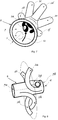
- the figures 1 to 8 illustrate preferred configurations of the slide comprising a sliding trail in form of a sliding tube, but these configurations may also be applied to slides wherein the sliding trail is made up of a single or multiple sliding rail(s) for guiding carts or wagons or a sliding tube provided with rail(s) arranged inside the tube for guiding carts or wagons.
- the slide of the invention comprises a sliding trail (2) made up of a tube having a substantially circular shaped section forming a three-dimensional curve occupying a volume around the rotation axis (4).
- the shape of the section of the tube may also be elliptic, oval, or other convex rounded shape without sharp angles.
- the trail is supported with fastenings (3) linking at least portions of the sliding trail to an axial part (5) disposed on a support (6). Portions of the sliding trail may also be linked each other with fasteners (3) if required by the shape of the trail curve.
- the axial part (5) is configured to rotate about a substantially horizontal rotation axis (4).
- the sliding trail (2) includes a first end forming an inlet (7) arranged in vicinity of the rotation axis (4) at an end of the axial part (5) and a second end, distinct from the first end, forming an outlet (9) allowing a rider to exit the trail.
- the curve of the sliding trail (2) is configured to form a sliding path between the inlet (7) and the outlet (9) extending in a volume around the rotation axis (4). Thanks to a motorized rotation of the sliding trail (2) about the rotation axis (4), the sliding path is permanently maintained on a slope directed downwards or upwards, depending on the angular position and the curvature of the rotating sliding trail (2).
- the support (6) is constructed in such a way to strongly hold the curved sliding trail and to allow its free rotation about the axis (4).
- a platform (11) provided with stairs or an elevator allows riders to access to the inlet (7) placed in the vicinity of the rotation axis (4).
- the slide is provided with a frame structure (1) holding one or a plurality of sliding tubes (2) with fastenings (3) distributed along the outline frame (1 a) of the frame structure (1) which is also attached to the axial part (5) with fastenings (3).
- the sliding tube (2) is attached to the frame structure (1) having at least one outline frame (1 a, 1 b) of predefined shape and a rotation axis (4) arranged substantially horizontally.
- the fastenings (3) link at least the outline frame (1 a, 1 b) to portions of the curved sliding tube (2).
- some fastenings (3) may also link portions of the tube (2) each other.
- the embodiment of figure 2 includes one circular outline frame (1a) supporting one sliding tube (2) forming circumvolutions turning in a volume around the rotation axis (4) of the circular outline frame (1 a).
- the outline frame (1 a) may have various shapes other than a circle, such as a star or a polygon with rectilinear or curved sides etc. depending on esthetic criteria set by the slide environment
- the frame structure (1) includes two opposite outline frames (1 a, 1 b) attached together with spacers (1 c).
- the shape of the outline frames (1a, 1b) may be different from a circle. Furthermore they may be each of different shapes or shifted each other or arranged in quincunx particularly in case of star or polygonal shapes.
- the sliding tube(s) (2) forming a more or less complex three-dimensional curve attached with the fastenings (3) is arranged around the rotation axis (4) of the frame structure (1) and extends in a volume defined between the two opposite outline frames (1 a, 1 b) and also outside by portions in the vicinity of this volume.
- FIG. 3 and 4 show some tubes configurations where turns of the curve go out the frame structure (1). Portions of the curve may project beyond the frame structure (1) out of one or both sides of the outline frame (1 a, 1 b) as portions 2B and/or out of the edges of the outline frames (1 a, 1 b) as portions 2A.
- the rotation axis (4) of the frame structure (1) corresponding to a common central axis of the circular frame outlines (1 a, 1 b) is mounted substantially horizontally on a support (5, 6) for rotation of the frame structure (1) like a wheel.
- the rotation axis (4) may also be slightly inclined relatively to a horizontal plane by forming an angle in a range of some degrees up to about 30 degrees.
- Each sliding tube (2) attached to the frame structure (1) includes an inlet connected to a central piece called bifurcator (8) having an axis corresponding to the axis (4) of the wheel shaped frame structure (1).
- the other end of the sliding tube (2) consisting of the outlet (9) is directed to outside the edge of the frame structure (1).
- the outlet (9) is placed between the two opposite circular outline frames (1 a, 1 b).
- the outlet (9) may also end outside the outline frames (1 a, 1 b).
- the outlets of a part of the tubes may be directed outside the outline frames (1a, 1b) and the outlets of the other part may be directed between them.
- a rider accesses to an entry (7) placed at the center of the wheel by a platform (11) with stairs for example.
- the entry (7) communicates with the bifurcator (8) connected to the inlets of the tubes (2) which the rider chooses for sliding until the outlet (9) while the frame structure (1) rotates about the axis (4). Thanks to the central position of the entry (7), the rider can access to the inlets of the tubes during rotation of the wheel. Exiting the tubes (2) is also possible during rotation, the rider may fall into a static pool (10), or on a damping mattress, or slides until a conveyor synchronized with the wheel peripheral rotation speed.
- the rotation may be stopped to let riders entering into the inlet (7).
- the rotation may also be stopped to let riders exiting the sliding tube (2).
- One or a plurality of sliding three-dimensional curved tubes (2) may be attached to a frame structure (1).
- the rotation of the frame structure, respectively the tube (2) provides a compensation of riders height loss during slide, due to upwards movement of the tube (2) while riders are sliding inside the tube (s) (2).
- the curves of the tubes (2) are designed in such a way to be adapted to variable or constant frame rotational speeds providing various speeds and accelerations vectors profiles for riders sliding in the tube(s).
- tube may be designed for different thrill levels between easy or slow (low thrill) and difficult or fast (high thrill), these tubes being mounted on a same frame structure or wheel.
- the rotation speed of the frame structure may also vary to provide additional accelerations to the riders according to their position inside the tubes.
- the sliding tube(s) (2) is (are) preferably provided with sensors arranged inside along the sliding tube. These sensors are configured to detect a position of a rider on the sliding path so that rotation speed of the tube can be controlled. For example if a rider is on an upwards slope, the rotation speed may be accelerated allowing the rider to reach next downwards slope without being stopped. Sensors configured to stop the rotation at entering or exiting of riders may also be positioned at the inlet (7) and outlet (9).
- the height of the slide can be reduced for a given speed and sensations for the riders compared to conventional slides which include also curved tubes but starting from a high tower.
- the sliding tubes (2) are preferably made in colored opaque, transparent plastic or fiberglass material or in any other appropriate material as stainless steel.
- the material structure as for example polished or rough internal walls and/or its visual aspect may change in predetermined portions of the tube to provide different sliding speeds and/or respectively decorative effects.
- the diameter of the sliding tube (2) is adapted to the riders which may slide individually or several in parallel or sit in inflatable rings.
- the sliding tubes (2) may include water injectors in. arranged inside the sliding tube (2) at positions along the sliding path determined to modify sliding speed by reducing friction of riders sliding inside the tube. Windows of any shape or lamps may also be added to the sliding tubes (2) for providing visual effects and animations during sliding.
- Figure 4 shows an embodiment of a slide with two opposite wheel shaped frame outlines (1 a, 1 b).
- the wheels are placed on four external rollers (13) maintained on the ground and configured for driving the rotation of the fame structure (1) about its rotation axis (4) thanks to a motor (14) installed on one of the rollers (13).
- This configuration allows a lighter frame structure, and provides possibility to easily exchange the wheel with different sliding tubes configurations.
- the embodiment of figure 5 comprises a frame structure (1) with outline frames in form of a polygon with curved sides.
- the slide is arranged in a cavity in the ground so that the rotation axis (4) is placed at ground level allowing riders to enter in the tubes without climbing steps, walking a ramp or taking an elevator.
- the sliding tubes may also be open or substantially half circular shaped section along the entire sliding path length or partly along portions of the sliding path length while the remaining portions are made up of closed tubes having a substantially circular shaped section as illustrated by figure 6 .
- the open tube portions may for example be positioned near the inlet (7) and/or the outlet (9).
- FIGS 7 illustrate a bifurcator (8) to which are connected the inlet (2a, 2b, 2c, 2d, 2e, 2f) of the sliding tubes (2).
- the riders enters into the entry (7) (arrow 12) and choose a tube for sliding.
- the bifurcator (8) of figure 8 includes two opposite entries (7a, 7b) at each side of the volume formed by the sliding tube (2) around the rotation axis (4).or at each side of the frame structure allowing riders to access in tubes inlets (2a, 2b, 2g, 2h, 2i) leading to tubes directed to opposite axis directions.
- the rotating frame structure (1) is configured or is configurable to move laterally according to an axis perpendicular to the rotation axis (4) in order to provide a balancing or shacking movement and additional slope variations in the tubes (2).
- the sliding trail(s) (2) is (are) made up, instead of a sliding tube, of a sliding rail structure comprising at least one rail following the three-dimensional curve of the sliding path.
- These rail(s) are configured to guide riding carts or wagons (20) rolling on the rail(s) or sliding by hanging on the rail(s).
- the sliding trail (2) is made up of a tube provided with at least one sliding rail arranged inside the tube and configured to guide riding carts or wagons rolling on the rail or sliding by hanging on the rail.
- the tube may be provided with sliding rails formed by guiding ribs or guiding grooves molded in the material of the internal wall of the tube or rails attached on the internal wall of the tube.
Landscapes
- Refuge Islands, Traffic Blockers, Or Guard Fence (AREA)
- Bearings For Parts Moving Linearly (AREA)
- Escalators And Moving Walkways (AREA)
- Handcart (AREA)
- Toys (AREA)
- Rehabilitation Tools (AREA)
- Types And Forms Of Lifts (AREA)
- Pinball Game Machines (AREA)
Claims (20)
- Toboggan de jeu et de loisir comprenant au moins une piste de glissement (2) formant une courbe tridimensionnelle supportée par des attaches (3) reliant au moins une portion de la piste de glissement (2) à une partie axiale (5) disposée sur un support (6), ladite partie axiale (5) étant configurée pour tourner autour d'un axe de rotation substantiellement horizontal (4), caractérisé en ce que:- la piste de glissement (2) inclut une première extrémité formant une entrée (7) disposée dans le voisinage de l'axe de rotation (4) à une extrémité de la partie axiale (5) et une deuxième extrémité, distincte de la première extrémité, formant une sortie (9) permettant de sortir de la piste (2),- la courbe de la piste de glissement (2) est configurée pour former un chemin de glissement entre l'entrée (7) et la sortie (9) s'étendant dans un volume autour de l'axe de rotation (4), ledit chemin de glissement étant maintenu en pente par une rotation de la piste de glissement (2) autour de l'axe de rotation (4), ladite rotation étant opérée par un moteur (14).
- Toboggan de jeu et de loisir selon la revendication 1 caractérisé en ce que la piste de glissement (2) est attachée à une structure de cadre (1) ayant au moins une structure de contour (1a, 1 b) de forme prédéfinie et un axe de rotation (4) disposé substantiellement horizontalement, les attaches (3) reliant au moins la structure de contour (1a, 1 b) à la partie axiale (5) et des portions de la piste de glissement (2) incurvée à ladite structure de contour (1a, 1b).
- Toboggan de jeu et de loisir selon la revendication 2 caractérisé en ce que la structure de cadre (1) est composée d'une structure de contour (1a).
- Toboggan de jeu et de loisir selon la revendication 2 caractérisé en ce que la structure de cadre (1) est composée de deux structures de contour opposées (1 a, 1 b) attachées ensemble avec des entretoises (1c).
- Toboggan de jeu et de loisir selon l'une quelconque des revendications 2 à 4 caractérisé en ce que la/les structure(s) de contour (1a, 1b) ont une forme sélectionnée dans le groupe comprenant un cercle, une étoile, un polygone à côtés rectilignes et un polygone à côtés incurvés.
- Toboggan de jeu et de loisir selon l'une quelconque des revendications 1 à 5 caractérisé en ce qu'il inclut une pluralité de pistes de glissement (2) dont les entrées (7) sont connectées à un bifurcateur (8) disposé autour de l'axe de rotation (4), ledit bifurcateur (8) comprenant au moins une entrée (7) pour des usagers.
- Toboggan de jeu et de loisir selon la revendication 6 caractérisé en ce que le bifurcateur (8) inclut deux entrées opposées (7a, 7b) placées à chaque côté du volume formé par la piste de glissement (2) autour de l'axe de rotation (4).
- Toboggan de jeu et de loisir selon l'une quelconque des revendications 1 à 7 caractérisé en ce que les courbes des pistes de glissement (2) sont conçues de façon à s'adapter à des vitesses de rotation variables fournissant divers profils de vecteurs de vitesses et d'accélérations pour des usagers glissant sur la/les piste(s) de glissement (2).
- Toboggan de jeu et de loisir selon l'une quelconque des revendications 1 à 8 caractérisé en ce qu'il est configuré ou configurable, en plus de la rotation, pour se mouvoir latéralement selon un axe perpendiculaire à l'axe de rotation (4) et fournissant un mouvement balançant ou secouant et des variations de pente additionnelles dans les pistes de glissement (2).
- Toboggan de jeu et de loisir selon l'une quelconque des revendications 1 à 9 caractérisé en ce que la/les piste(s) de glissement (2) est (sont) pourvue(s) de capteurs disposés le long de la piste de glissement, lesdits capteurs étant configurés pour détecter la position d'un usager utilisée pour contrôler la vitesse de rotation de la piste.
- Toboggan de jeu et de loisir selon la revendication 10 caractérisé en ce que la/les piste(s) de glissement (2) est (sont) pourvue(s) de capteurs disposés à l'entrée (7) et à la sortie (9) configurés pour arrêter la rotation de la/des piste(s) de glissement (2) à l'entrée ou à la sortie d'usagers glissant sur la/les piste(s) (2).
- Toboggan de jeu et de loisir selon l'une quelconque des revendications 1 à 11 caractérisé en ce que la/les piste(s) de glissement (2) est (sont) composée(s) de tube(s) de glissement ayant une section de forme substantiellement circulaire.
- Toboggan de jeu et de loisir selon la revendication 12 caractérisé en ce que les sorties (9) des tubes de glissement (2) sont dirigées vers un bassin statique (10), ou un matelas d'amortissement, ou un tapis roulant synchronisé avec la rotation du tube de glissement (2) autour de l'axe (4).
- Toboggan de jeu et de loisir selon l'une quelconque des revendications 1 à 11 caractérisé en ce que la piste de glissement (2) est composée d'un tube ouvert ayant une section de forme substantiellement semi-circulaire le long de la longueur entière du chemin de glissement ou partiellement le long de portions de la longueur du chemin de glissement tandis que les portions restantes sont composées de tubes fermés ayant une section de forme substantiellement circulaire.
- Toboggan de jeu et de loisir selon l'une quelconque des revendications 12 à 14 caractérisé en ce que le tube de glissement est composé de matière plastique ou de fibre de verre colorée opaque ou transparente ou d'acier inoxydable.
- Toboggan de jeu et de loisir selon l'une quelconque des revendications 12 à 15 caractérisé en ce que le tube de glissement est pourvu d'injecteurs d'eau disposés à l'intérieur du tube de glissement le long du chemin de glissement à des positions déterminées pour modifier la vitesse de glissement d'usagers à l'intérieur du tube.
- Toboggan de jeu et de loisir selon l'une quelconque des revendications 1 à 11 caractérisé en ce que la/les piste(s) de glissement (2) est (sont) composée(s) d'une structure de rail de glissement comprenant au moins un rail suivant la courbe tridimensionnelle du chemin de glissement.
- Toboggan de jeu et de loisir selon la revendication 17 caractérisé en ce que la structure de rail de glissement est configurée pour guider des charrettes ou wagons pour passagers (20) roulant sur le(s) rail(s) ou glissant en étant suspendus au(x) rail(s).
- Toboggan de jeu et de loisir selon l'une quelconque des revendications 1 à 15 caractérisé en ce que la piste de glissement (2) est composée d'un tube pourvu d'au moins un rail de glissement disposé dans le tube, ledit au moins un rail de glissement étant configuré pour guider des charrettes ou wagons pour passagers (20) roulant sur le rail ou glissant en étant suspendus au rail.
- Toboggan de jeu et de loisir selon l'une quelconque des revendications 1 à 19 caractérisé en ce que l'axe de rotation (4) est incliné par rapport à un plan horizontal formant un angle ayant une valeur comprise entre quelques degrés et environ 30 degrés.
Priority Applications (1)
| Application Number | Priority Date | Filing Date | Title |
|---|---|---|---|
| EP13713830.1A EP2830729B1 (fr) | 2012-03-27 | 2013-03-26 | Toboggan de loisir et de jeu |
Applications Claiming Priority (5)
| Application Number | Priority Date | Filing Date | Title |
|---|---|---|---|
| US201261615933P | 2012-03-27 | 2012-03-27 | |
| EP12161573.6A EP2644238A1 (fr) | 2012-03-27 | 2012-03-27 | Glissière de loisirs et de divertissement |
| EP12187280 | 2012-10-04 | ||
| EP13713830.1A EP2830729B1 (fr) | 2012-03-27 | 2013-03-26 | Toboggan de loisir et de jeu |
| PCT/EP2013/056354 WO2013144117A1 (fr) | 2012-03-27 | 2013-03-26 | Toboggan de loisir et de jeu |
Publications (2)
| Publication Number | Publication Date |
|---|---|
| EP2830729A1 EP2830729A1 (fr) | 2015-02-04 |
| EP2830729B1 true EP2830729B1 (fr) | 2016-05-18 |
Family
ID=49258266
Family Applications (1)
| Application Number | Title | Priority Date | Filing Date |
|---|---|---|---|
| EP13713830.1A Active EP2830729B1 (fr) | 2012-03-27 | 2013-03-26 | Toboggan de loisir et de jeu |
Country Status (8)
| Country | Link |
|---|---|
| US (1) | US9440155B2 (fr) |
| EP (1) | EP2830729B1 (fr) |
| CN (1) | CN104254375B (fr) |
| CA (1) | CA2867514C (fr) |
| ES (1) | ES2586952T3 (fr) |
| PL (1) | PL2830729T3 (fr) |
| RU (1) | RU2611030C2 (fr) |
| WO (1) | WO2013144117A1 (fr) |
Families Citing this family (12)
| Publication number | Priority date | Publication date | Assignee | Title |
|---|---|---|---|---|
| CN106546765A (zh) * | 2016-10-28 | 2017-03-29 | 中国船舶科学研究中心(中国船舶重工集团公司第七0二研究所) | 基于水滑梯的数字化竞速测量装置 |
| CN106994250B (zh) * | 2017-01-06 | 2020-03-06 | 北京米娅文化发展有限公司 | 游具 |
| CN108310778A (zh) * | 2018-05-09 | 2018-07-24 | 广州海山游乐科技股份有限公司 | 一种娱乐滑道 |
| CN109420341A (zh) * | 2018-08-25 | 2019-03-05 | 张亮 | 滑行车体加速度解析方法 |
| EP3702009A1 (fr) * | 2019-02-27 | 2020-09-02 | Fischer Design-Concepts Sàrl | Attraction d'amusement de l'eau |
| DE102021107558A1 (de) * | 2021-03-25 | 2022-09-29 | Aquarena Holding Gmbh | Rutsche, insbesondere Wasserrutsche |
| DE102021107560A1 (de) * | 2021-03-25 | 2022-09-29 | Aquarena Holding Gmbh | Verfahren zur Steuerung einer Rutschrichtung in einer Weiche sowie Weiche für eine Rutsche, insbesondere Wasserrutsche |
| EP4134145A1 (fr) * | 2021-08-12 | 2023-02-15 | Atelier F FZ LLE | Élément de flexion pour une glissoire d'eau |
| WO2023082026A1 (fr) | 2021-11-15 | 2023-05-19 | Whitewater West Industries Ltd. | Élément de toboggan aquatique à cuves multiples conjointes |
| EP4433184A4 (fr) | 2021-11-15 | 2025-10-15 | Whitewater West Ind Ltd | Élément de divertissement rotatif associé à l'eau |
| CA216495S (en) * | 2022-10-19 | 2024-08-06 | Proslide Technology Inc | Water ride feature |
| USD1097034S1 (en) * | 2023-11-05 | 2025-10-07 | Polin Su Parklari Ve Havuz Sistemleri Anonim Sirketi | Interflow waterslide |
Family Cites Families (11)
| Publication number | Priority date | Publication date | Assignee | Title |
|---|---|---|---|---|
| JP2577242B2 (ja) * | 1988-03-25 | 1997-01-29 | 株式会社石井鐵工所 | シーソー機構を設けた水上滑り台 |
| US4836521A (en) * | 1988-09-23 | 1989-06-06 | Barber Gerald L | Whirlpool amusement ride |
| US5433671A (en) | 1993-12-27 | 1995-07-18 | Davis; Walter D. | Water amusement ride |
| US6857964B2 (en) * | 2002-06-18 | 2005-02-22 | Proslide Technology, Inc. | Reducing radius slide feature |
| US7713134B2 (en) | 2002-06-18 | 2010-05-11 | Proslide Technology Inc. | Reducing radius slide feature |
| AU2007336963B2 (en) * | 2006-12-21 | 2011-03-31 | Rail-Veyor Technologies Global Inc. | Method of controlling a rail transport system for conveying bulk materials |
| RU74817U1 (ru) * | 2008-02-08 | 2008-07-20 | Викторий Данилович Девяткин | Водный трамплин для прыжков на лыжах |
| GB2460223A (en) * | 2008-05-19 | 2009-11-25 | David John Cuttell | Water ride conveyor system |
| EA013705B1 (ru) * | 2008-06-18 | 2010-06-30 | Акварена Фрайцайтанлаген Гмбх | Водный спуск |
| GB0818483D0 (en) | 2008-10-08 | 2008-11-12 | Cuttell David J | Water or leisure slide |
| EP2637756A4 (fr) * | 2010-11-12 | 2014-04-16 | Splashtacular Inc | Toboggan récréatif comportant une section mobile |
-
2013
- 2013-03-26 RU RU2014140468A patent/RU2611030C2/ru active
- 2013-03-26 PL PL13713830.1T patent/PL2830729T3/pl unknown
- 2013-03-26 EP EP13713830.1A patent/EP2830729B1/fr active Active
- 2013-03-26 ES ES13713830.1T patent/ES2586952T3/es active Active
- 2013-03-26 US US14/388,079 patent/US9440155B2/en active Active
- 2013-03-26 CN CN201380017304.2A patent/CN104254375B/zh active Active
- 2013-03-26 WO PCT/EP2013/056354 patent/WO2013144117A1/fr not_active Ceased
- 2013-03-26 CA CA2867514A patent/CA2867514C/fr active Active
Also Published As
| Publication number | Publication date |
|---|---|
| EP2830729A1 (fr) | 2015-02-04 |
| PL2830729T3 (pl) | 2016-11-30 |
| ES2586952T3 (es) | 2016-10-19 |
| CA2867514C (fr) | 2019-11-26 |
| RU2611030C2 (ru) | 2017-02-17 |
| US9440155B2 (en) | 2016-09-13 |
| RU2014140468A (ru) | 2016-05-20 |
| US20150045128A1 (en) | 2015-02-12 |
| CN104254375B (zh) | 2016-09-07 |
| WO2013144117A1 (fr) | 2013-10-03 |
| CA2867514A1 (fr) | 2013-10-03 |
| CN104254375A (zh) | 2014-12-31 |
Similar Documents
| Publication | Publication Date | Title |
|---|---|---|
| EP2830729B1 (fr) | Toboggan de loisir et de jeu | |
| US20240042337A1 (en) | Water ride | |
| US8490549B2 (en) | Tower ride | |
| US8262494B2 (en) | Reducing radius slide feature | |
| EP2644238A1 (fr) | Glissière de loisirs et de divertissement | |
| US1371528A (en) | Multiform amusement-wheel | |
| NZ618878B2 (en) | Tower ride |
Legal Events
| Date | Code | Title | Description |
|---|---|---|---|
| PUAI | Public reference made under article 153(3) epc to a published international application that has entered the european phase |
Free format text: ORIGINAL CODE: 0009012 |
|
| 17P | Request for examination filed |
Effective date: 20141006 |
|
| AK | Designated contracting states |
Kind code of ref document: A1 Designated state(s): AL AT BE BG CH CY CZ DE DK EE ES FI FR GB GR HR HU IE IS IT LI LT LU LV MC MK MT NL NO PL PT RO RS SE SI SK SM TR |
|
| AX | Request for extension of the european patent |
Extension state: BA ME |
|
| DAX | Request for extension of the european patent (deleted) | ||
| GRAP | Despatch of communication of intention to grant a patent |
Free format text: ORIGINAL CODE: EPIDOSNIGR1 |
|
| INTG | Intention to grant announced |
Effective date: 20150930 |
|
| GRAS | Grant fee paid |
Free format text: ORIGINAL CODE: EPIDOSNIGR3 |
|
| INTG | Intention to grant announced |
Effective date: 20160226 |
|
| GRAA | (expected) grant |
Free format text: ORIGINAL CODE: 0009210 |
|
| AK | Designated contracting states |
Kind code of ref document: B1 Designated state(s): AL AT BE BG CH CY CZ DE DK EE ES FI FR GB GR HR HU IE IS IT LI LT LU LV MC MK MT NL NO PL PT RO RS SE SI SK SM TR |
|
| REG | Reference to a national code |
Ref country code: GB Ref legal event code: FG4D |
|
| REG | Reference to a national code |
Ref country code: CH Ref legal event code: EP |
|
| REG | Reference to a national code |
Ref country code: IE Ref legal event code: FG4D Ref country code: AT Ref legal event code: REF Ref document number: 799912 Country of ref document: AT Kind code of ref document: T Effective date: 20160615 |
|
| REG | Reference to a national code |
Ref country code: DE Ref legal event code: R096 Ref document number: 602013007648 Country of ref document: DE |
|
| REG | Reference to a national code |
Ref country code: CH Ref legal event code: NV Representative=s name: LEMAN CONSULTING S.A., CH |
|
| REG | Reference to a national code |
Ref country code: NL Ref legal event code: MP Effective date: 20160518 |
|
| REG | Reference to a national code |
Ref country code: LT Ref legal event code: MG4D |
|
| REG | Reference to a national code |
Ref country code: ES Ref legal event code: FG2A Ref document number: 2586952 Country of ref document: ES Kind code of ref document: T3 Effective date: 20161019 |
|
| PG25 | Lapsed in a contracting state [announced via postgrant information from national office to epo] |
Ref country code: NL Free format text: LAPSE BECAUSE OF FAILURE TO SUBMIT A TRANSLATION OF THE DESCRIPTION OR TO PAY THE FEE WITHIN THE PRESCRIBED TIME-LIMIT Effective date: 20160518 Ref country code: NO Free format text: LAPSE BECAUSE OF FAILURE TO SUBMIT A TRANSLATION OF THE DESCRIPTION OR TO PAY THE FEE WITHIN THE PRESCRIBED TIME-LIMIT Effective date: 20160818 Ref country code: FI Free format text: LAPSE BECAUSE OF FAILURE TO SUBMIT A TRANSLATION OF THE DESCRIPTION OR TO PAY THE FEE WITHIN THE PRESCRIBED TIME-LIMIT Effective date: 20160518 Ref country code: LT Free format text: LAPSE BECAUSE OF FAILURE TO SUBMIT A TRANSLATION OF THE DESCRIPTION OR TO PAY THE FEE WITHIN THE PRESCRIBED TIME-LIMIT Effective date: 20160518 |
|
| REG | Reference to a national code |
Ref country code: AT Ref legal event code: MK05 Ref document number: 799912 Country of ref document: AT Kind code of ref document: T Effective date: 20160518 |
|
| PG25 | Lapsed in a contracting state [announced via postgrant information from national office to epo] |
Ref country code: RS Free format text: LAPSE BECAUSE OF FAILURE TO SUBMIT A TRANSLATION OF THE DESCRIPTION OR TO PAY THE FEE WITHIN THE PRESCRIBED TIME-LIMIT Effective date: 20160518 Ref country code: PT Free format text: LAPSE BECAUSE OF FAILURE TO SUBMIT A TRANSLATION OF THE DESCRIPTION OR TO PAY THE FEE WITHIN THE PRESCRIBED TIME-LIMIT Effective date: 20160919 Ref country code: SE Free format text: LAPSE BECAUSE OF FAILURE TO SUBMIT A TRANSLATION OF THE DESCRIPTION OR TO PAY THE FEE WITHIN THE PRESCRIBED TIME-LIMIT Effective date: 20160518 Ref country code: GR Free format text: LAPSE BECAUSE OF FAILURE TO SUBMIT A TRANSLATION OF THE DESCRIPTION OR TO PAY THE FEE WITHIN THE PRESCRIBED TIME-LIMIT Effective date: 20160819 Ref country code: LV Free format text: LAPSE BECAUSE OF FAILURE TO SUBMIT A TRANSLATION OF THE DESCRIPTION OR TO PAY THE FEE WITHIN THE PRESCRIBED TIME-LIMIT Effective date: 20160518 Ref country code: HR Free format text: LAPSE BECAUSE OF FAILURE TO SUBMIT A TRANSLATION OF THE DESCRIPTION OR TO PAY THE FEE WITHIN THE PRESCRIBED TIME-LIMIT Effective date: 20160518 |
|
| PG25 | Lapsed in a contracting state [announced via postgrant information from national office to epo] |
Ref country code: DK Free format text: LAPSE BECAUSE OF FAILURE TO SUBMIT A TRANSLATION OF THE DESCRIPTION OR TO PAY THE FEE WITHIN THE PRESCRIBED TIME-LIMIT Effective date: 20160518 Ref country code: EE Free format text: LAPSE BECAUSE OF FAILURE TO SUBMIT A TRANSLATION OF THE DESCRIPTION OR TO PAY THE FEE WITHIN THE PRESCRIBED TIME-LIMIT Effective date: 20160518 Ref country code: CZ Free format text: LAPSE BECAUSE OF FAILURE TO SUBMIT A TRANSLATION OF THE DESCRIPTION OR TO PAY THE FEE WITHIN THE PRESCRIBED TIME-LIMIT Effective date: 20160518 Ref country code: RO Free format text: LAPSE BECAUSE OF FAILURE TO SUBMIT A TRANSLATION OF THE DESCRIPTION OR TO PAY THE FEE WITHIN THE PRESCRIBED TIME-LIMIT Effective date: 20160518 Ref country code: SK Free format text: LAPSE BECAUSE OF FAILURE TO SUBMIT A TRANSLATION OF THE DESCRIPTION OR TO PAY THE FEE WITHIN THE PRESCRIBED TIME-LIMIT Effective date: 20160518 |
|
| REG | Reference to a national code |
Ref country code: DE Ref legal event code: R097 Ref document number: 602013007648 Country of ref document: DE |
|
| PG25 | Lapsed in a contracting state [announced via postgrant information from national office to epo] |
Ref country code: SM Free format text: LAPSE BECAUSE OF FAILURE TO SUBMIT A TRANSLATION OF THE DESCRIPTION OR TO PAY THE FEE WITHIN THE PRESCRIBED TIME-LIMIT Effective date: 20160518 Ref country code: BE Free format text: LAPSE BECAUSE OF FAILURE TO SUBMIT A TRANSLATION OF THE DESCRIPTION OR TO PAY THE FEE WITHIN THE PRESCRIBED TIME-LIMIT Effective date: 20160518 Ref country code: AT Free format text: LAPSE BECAUSE OF FAILURE TO SUBMIT A TRANSLATION OF THE DESCRIPTION OR TO PAY THE FEE WITHIN THE PRESCRIBED TIME-LIMIT Effective date: 20160518 |
|
| REG | Reference to a national code |
Ref country code: FR Ref legal event code: PLFP Year of fee payment: 5 |
|
| PLBE | No opposition filed within time limit |
Free format text: ORIGINAL CODE: 0009261 |
|
| STAA | Information on the status of an ep patent application or granted ep patent |
Free format text: STATUS: NO OPPOSITION FILED WITHIN TIME LIMIT |
|
| 26N | No opposition filed |
Effective date: 20170221 |
|
| PG25 | Lapsed in a contracting state [announced via postgrant information from national office to epo] |
Ref country code: SI Free format text: LAPSE BECAUSE OF FAILURE TO SUBMIT A TRANSLATION OF THE DESCRIPTION OR TO PAY THE FEE WITHIN THE PRESCRIBED TIME-LIMIT Effective date: 20160518 |
|
| GBPC | Gb: european patent ceased through non-payment of renewal fee |
Effective date: 20170326 |
|
| PG25 | Lapsed in a contracting state [announced via postgrant information from national office to epo] |
Ref country code: MC Free format text: LAPSE BECAUSE OF FAILURE TO SUBMIT A TRANSLATION OF THE DESCRIPTION OR TO PAY THE FEE WITHIN THE PRESCRIBED TIME-LIMIT Effective date: 20160518 |
|
| REG | Reference to a national code |
Ref country code: IE Ref legal event code: MM4A |
|
| PG25 | Lapsed in a contracting state [announced via postgrant information from national office to epo] |
Ref country code: LU Free format text: LAPSE BECAUSE OF NON-PAYMENT OF DUE FEES Effective date: 20170326 |
|
| PG25 | Lapsed in a contracting state [announced via postgrant information from national office to epo] |
Ref country code: IE Free format text: LAPSE BECAUSE OF NON-PAYMENT OF DUE FEES Effective date: 20170326 Ref country code: GB Free format text: LAPSE BECAUSE OF NON-PAYMENT OF DUE FEES Effective date: 20170326 |
|
| REG | Reference to a national code |
Ref country code: FR Ref legal event code: PLFP Year of fee payment: 6 |
|
| REG | Reference to a national code |
Ref country code: CH Ref legal event code: NV Representative=s name: IP PARTNERS J. WENGER, CH |
|
| PG25 | Lapsed in a contracting state [announced via postgrant information from national office to epo] |
Ref country code: MT Free format text: LAPSE BECAUSE OF NON-PAYMENT OF DUE FEES Effective date: 20170326 |
|
| PG25 | Lapsed in a contracting state [announced via postgrant information from national office to epo] |
Ref country code: AL Free format text: LAPSE BECAUSE OF FAILURE TO SUBMIT A TRANSLATION OF THE DESCRIPTION OR TO PAY THE FEE WITHIN THE PRESCRIBED TIME-LIMIT Effective date: 20160518 |
|
| PG25 | Lapsed in a contracting state [announced via postgrant information from national office to epo] |
Ref country code: HU Free format text: LAPSE BECAUSE OF FAILURE TO SUBMIT A TRANSLATION OF THE DESCRIPTION OR TO PAY THE FEE WITHIN THE PRESCRIBED TIME-LIMIT; INVALID AB INITIO Effective date: 20130326 |
|
| PG25 | Lapsed in a contracting state [announced via postgrant information from national office to epo] |
Ref country code: BG Free format text: LAPSE BECAUSE OF FAILURE TO SUBMIT A TRANSLATION OF THE DESCRIPTION OR TO PAY THE FEE WITHIN THE PRESCRIBED TIME-LIMIT Effective date: 20160518 |
|
| PG25 | Lapsed in a contracting state [announced via postgrant information from national office to epo] |
Ref country code: CY Free format text: LAPSE BECAUSE OF FAILURE TO SUBMIT A TRANSLATION OF THE DESCRIPTION OR TO PAY THE FEE WITHIN THE PRESCRIBED TIME-LIMIT Effective date: 20160518 |
|
| PG25 | Lapsed in a contracting state [announced via postgrant information from national office to epo] |
Ref country code: MK Free format text: LAPSE BECAUSE OF FAILURE TO SUBMIT A TRANSLATION OF THE DESCRIPTION OR TO PAY THE FEE WITHIN THE PRESCRIBED TIME-LIMIT Effective date: 20160518 |
|
| PG25 | Lapsed in a contracting state [announced via postgrant information from national office to epo] |
Ref country code: IS Free format text: LAPSE BECAUSE OF FAILURE TO SUBMIT A TRANSLATION OF THE DESCRIPTION OR TO PAY THE FEE WITHIN THE PRESCRIBED TIME-LIMIT Effective date: 20160918 |
|
| PGFP | Annual fee paid to national office [announced via postgrant information from national office to epo] |
Ref country code: ES Payment date: 20250429 Year of fee payment: 13 |
|
| PGFP | Annual fee paid to national office [announced via postgrant information from national office to epo] |
Ref country code: CH Payment date: 20250401 Year of fee payment: 13 |
|
| REG | Reference to a national code |
Ref country code: CH Ref legal event code: U11 Free format text: ST27 STATUS EVENT CODE: U-0-0-U10-U11 (AS PROVIDED BY THE NATIONAL OFFICE) Effective date: 20260401 |
|
| PGFP | Annual fee paid to national office [announced via postgrant information from national office to epo] |
Ref country code: DE Payment date: 20260319 Year of fee payment: 14 |
|
| PGFP | Annual fee paid to national office [announced via postgrant information from national office to epo] |
Ref country code: IT Payment date: 20260324 Year of fee payment: 14 |
|
| PGFP | Annual fee paid to national office [announced via postgrant information from national office to epo] |
Ref country code: FR Payment date: 20260320 Year of fee payment: 14 |
|
| PGFP | Annual fee paid to national office [announced via postgrant information from national office to epo] |
Ref country code: TR Payment date: 20260323 Year of fee payment: 14 |
|
| PGFP | Annual fee paid to national office [announced via postgrant information from national office to epo] |
Ref country code: PL Payment date: 20260218 Year of fee payment: 14 |