EP2830739B1 - Procédé pour l'élimination de dioxyde de carbone avec solution contenant de l'ammoniaque - Google Patents
Procédé pour l'élimination de dioxyde de carbone avec solution contenant de l'ammoniaque Download PDFInfo
- Publication number
- EP2830739B1 EP2830739B1 EP13722098.4A EP13722098A EP2830739B1 EP 2830739 B1 EP2830739 B1 EP 2830739B1 EP 13722098 A EP13722098 A EP 13722098A EP 2830739 B1 EP2830739 B1 EP 2830739B1
- Authority
- EP
- European Patent Office
- Prior art keywords
- stream
- carbon dioxide
- absorber
- gas
- ammonia
- Prior art date
- Legal status (The legal status is an assumption and is not a legal conclusion. Google has not performed a legal analysis and makes no representation as to the accuracy of the status listed.)
- Active
Links
Images


Classifications
-
- B—PERFORMING OPERATIONS; TRANSPORTING
- B01—PHYSICAL OR CHEMICAL PROCESSES OR APPARATUS IN GENERAL
- B01D—SEPARATION
- B01D53/00—Separation of gases or vapours; Recovering vapours of volatile solvents from gases; Chemical or biological purification of waste gases, e.g. engine exhaust gases, smoke, fumes, flue gases, aerosols
- B01D53/34—Chemical or biological purification of waste gases
- B01D53/46—Removing components of defined structure
- B01D53/62—Carbon oxides
-
- B—PERFORMING OPERATIONS; TRANSPORTING
- B01—PHYSICAL OR CHEMICAL PROCESSES OR APPARATUS IN GENERAL
- B01D—SEPARATION
- B01D53/00—Separation of gases or vapours; Recovering vapours of volatile solvents from gases; Chemical or biological purification of waste gases, e.g. engine exhaust gases, smoke, fumes, flue gases, aerosols
- B01D53/14—Separation of gases or vapours; Recovering vapours of volatile solvents from gases; Chemical or biological purification of waste gases, e.g. engine exhaust gases, smoke, fumes, flue gases, aerosols by absorption
- B01D53/1425—Regeneration of liquid absorbents
-
- B—PERFORMING OPERATIONS; TRANSPORTING
- B01—PHYSICAL OR CHEMICAL PROCESSES OR APPARATUS IN GENERAL
- B01D—SEPARATION
- B01D53/00—Separation of gases or vapours; Recovering vapours of volatile solvents from gases; Chemical or biological purification of waste gases, e.g. engine exhaust gases, smoke, fumes, flue gases, aerosols
- B01D53/14—Separation of gases or vapours; Recovering vapours of volatile solvents from gases; Chemical or biological purification of waste gases, e.g. engine exhaust gases, smoke, fumes, flue gases, aerosols by absorption
- B01D53/1456—Removing acid components
- B01D53/1475—Removing carbon dioxide
-
- B—PERFORMING OPERATIONS; TRANSPORTING
- B01—PHYSICAL OR CHEMICAL PROCESSES OR APPARATUS IN GENERAL
- B01D—SEPARATION
- B01D53/00—Separation of gases or vapours; Recovering vapours of volatile solvents from gases; Chemical or biological purification of waste gases, e.g. engine exhaust gases, smoke, fumes, flue gases, aerosols
- B01D53/34—Chemical or biological purification of waste gases
- B01D53/96—Regeneration, reactivation or recycling of reactants
-
- B—PERFORMING OPERATIONS; TRANSPORTING
- B01—PHYSICAL OR CHEMICAL PROCESSES OR APPARATUS IN GENERAL
- B01D—SEPARATION
- B01D2252/00—Absorbents, i.e. solvents and liquid materials for gas absorption
- B01D2252/10—Inorganic absorbents
- B01D2252/102—Ammonia
-
- B—PERFORMING OPERATIONS; TRANSPORTING
- B01—PHYSICAL OR CHEMICAL PROCESSES OR APPARATUS IN GENERAL
- B01D—SEPARATION
- B01D2252/00—Absorbents, i.e. solvents and liquid materials for gas absorption
- B01D2252/60—Additives
- B01D2252/602—Activators, promoting agents, catalytic agents or enzymes
-
- B—PERFORMING OPERATIONS; TRANSPORTING
- B01—PHYSICAL OR CHEMICAL PROCESSES OR APPARATUS IN GENERAL
- B01D—SEPARATION
- B01D2255/00—Catalysts
- B01D2255/80—Type of catalytic reaction
- B01D2255/804—Enzymatic
-
- B—PERFORMING OPERATIONS; TRANSPORTING
- B01—PHYSICAL OR CHEMICAL PROCESSES OR APPARATUS IN GENERAL
- B01D—SEPARATION
- B01D2257/00—Components to be removed
- B01D2257/50—Carbon oxides
- B01D2257/504—Carbon dioxide
-
- B—PERFORMING OPERATIONS; TRANSPORTING
- B01—PHYSICAL OR CHEMICAL PROCESSES OR APPARATUS IN GENERAL
- B01D—SEPARATION
- B01D2258/00—Sources of waste gases
- B01D2258/02—Other waste gases
- B01D2258/0283—Flue gases
-
- B—PERFORMING OPERATIONS; TRANSPORTING
- B01—PHYSICAL OR CHEMICAL PROCESSES OR APPARATUS IN GENERAL
- B01D—SEPARATION
- B01D2259/00—Type of treatment
- B01D2259/12—Methods and means for introducing reactants
- B01D2259/124—Liquid reactants
-
- Y—GENERAL TAGGING OF NEW TECHNOLOGICAL DEVELOPMENTS; GENERAL TAGGING OF CROSS-SECTIONAL TECHNOLOGIES SPANNING OVER SEVERAL SECTIONS OF THE IPC; TECHNICAL SUBJECTS COVERED BY FORMER USPC CROSS-REFERENCE ART COLLECTIONS [XRACs] AND DIGESTS
- Y02—TECHNOLOGIES OR APPLICATIONS FOR MITIGATION OR ADAPTATION AGAINST CLIMATE CHANGE
- Y02A—TECHNOLOGIES FOR ADAPTATION TO CLIMATE CHANGE
- Y02A50/00—TECHNOLOGIES FOR ADAPTATION TO CLIMATE CHANGE in human health protection, e.g. against extreme weather
- Y02A50/20—Air quality improvement or preservation, e.g. vehicle emission control or emission reduction by using catalytic converters
-
- Y—GENERAL TAGGING OF NEW TECHNOLOGICAL DEVELOPMENTS; GENERAL TAGGING OF CROSS-SECTIONAL TECHNOLOGIES SPANNING OVER SEVERAL SECTIONS OF THE IPC; TECHNICAL SUBJECTS COVERED BY FORMER USPC CROSS-REFERENCE ART COLLECTIONS [XRACs] AND DIGESTS
- Y02—TECHNOLOGIES OR APPLICATIONS FOR MITIGATION OR ADAPTATION AGAINST CLIMATE CHANGE
- Y02C—CAPTURE, STORAGE, SEQUESTRATION OR DISPOSAL OF GREENHOUSE GASES [GHG]
- Y02C20/00—Capture or disposal of greenhouse gases
- Y02C20/40—Capture or disposal of greenhouse gases of CO2
Definitions
- the present disclosure is generally directed to the removal of carbon dioxide from a gas stream. More particularly, the present disclosure is directed to a system and method for precipitating ammonium salts as a means to separate a carbon dioxide rich phase from a carbon dioxide semi-lean phase and thus reduce the energy requirements during regeneration.
- Combustion of fossil fuels typically produces an exhaust gas stream (commonly referred to as a "flue gas stream”) that contains contaminants, such as carbon dioxide (CO 2 ), sulfur oxides (SOx), nitrogen oxides (NOx), mercury, and carbon containing species, as well as particulate matter such as dust or fly ash.
- a flue gas stream typically contains contaminants, such as carbon dioxide (CO 2 ), sulfur oxides (SOx), nitrogen oxides (NOx), mercury, and carbon containing species, as well as particulate matter such as dust or fly ash.
- carbon dioxide is removed from a gas stream by introducing the gas stream to an absorber column ("absorber").
- the gas stream contacts a solvent in a counter-current flow within the absorber. Contact between the solvent and the gas stream allows the solvent to absorb and thus remove the CO 2 from the gas stream.
- the gas stream that is substantially free of the CO 2 is typically sent to an exhaust stack while the CO 2 rich solvent is processed in a regenerator to remove the CO 2 . The solvent from the regenerator is then cycled back to the absorber for further use.
- the solution reactions between the solvent(s) and the carbon dioxide may form a precipitate such as, for example, ammonium salts.
- a chilled ammonia absorption process (often referred to as "CAP"), the process operates at a low temperature (typically below 20°C) and high CO 2 loadings to minimize ammonia volatility.
- High ammonia molarity and high recirculation rate (of the ammonia) around the absorber may be needed to achieve the desired CO 2 removal from the flue gas stream.
- ammonia loss In addition to achieving the desired amount of CO 2 removal from the flue gas stream, it is also desirable to reduce ammonia loss. Reduction of ammonia loss involves low temperatures and low free ammonia molarity. Also, an ammonia solvent has the tendency to precipitate ammonium bicarbonate at high free ammonia molarity, low temperature, and high CO 2 loading, thus limiting the cyclic capacity of the solvent between the absorber and the regenerator. The consequence of this is that higher circulation rates are required between the absorber and regenerator to achieve the desired CO 2 capture rates.
- US 2012/0063975 A1 discloses a method for removing carbon dioxide from a gas comprising introducing a carbon dioxide-containing gas stream to an absorber; contacting the gas stream with an ammonia-containing solvent, the ammonia-containing solvent having a molarity between about 0.5 molar and about 13 molar; and absorbing the carbon dioxide from the gas stream with the ammonia-containing solvent, thereby removing the carbon dioxide from the gas stream and forming a CO 2 -rich stream. Similar methods are described in US 2008/0307968 A1 and US 2011/0311429 A1 .
- US 2011/0064636 A1 proposes a method for removing carbon dioxide from a gas.
- the absorber arrangement comprises three absorber columns. At the bottom of the first absorber column flue gas is introduced and ammoniated solution is discharged and cooled to create precipitates that are subsequently separated be means of a hydrocyclone. The separated precipitates are regenerated and fed back to the third absorber column. The solids free solution from the hydrocyclone is fed into the second absorber column.
- US 2011/0061533 A1 proposes a method of removing CO 2 from a process gas, the method comprising: contacting an ammoniated solution with the process gas in an absorption arrangement, the ammoniated solution capturing at least a part of the CO 2 of the process gas, wherein the molar ratio R of ammonia to carbon dioxide in the ammoniated solution is controlled such that substantially no precipitation of solids occurs within the absorption arrangement; allowing ammoniated solution including captured CO 2 to exit the absorption arrangement; cooling the ammoniated solution that has exited the absorption arrangement, wherein at least a part of the captured CO 2 is precipitated as solid salt; separating at least a part of the precipitated salt from the ammoniated solution; heating the ammoniated solution from which the at least a part of the precipitated salt has been separated, such that substantially no solids are present in the heated ammoniated solution; and allowing the heated ammoniated solution to re-enter the absorption arrangement.
- the present invention provides a method for removing carbon dioxide from a gas according to claim 1.
- a method for removing carbon dioxide from a gas comprising introducing a carbon dioxide-containing gas stream to an absorber; contacting the gas stream with an ammonia-containing solvent, the ammonia-containing solvent having a molarity between about 0.5 molar and about 13 molar; and absorbing the carbon dioxide from the gas stream with the ammonia-containing solvent, thereby removing the carbon dioxide from the gas stream and forming a CO 2 -rich stream.
- a method for removing carbon dioxide from a carbon dioxide-containing gas stream comprising introducing a carbon dioxide-containing gas stream to an absorber having a temperature of about 45°C or less; contacting the carbon dioxide-containing gas stream with an ammonia-containing solvent having a molarity between about 0.5 molar and about 13 molar; absorbing carbon dioxide from the gas stream; and forming a precipitate between the carbon dioxide and the ammonia-containing solvent.
- a system for removing carbon dioxide from a gas stream comprising an absorber configured to receive a carbon dioxide-containing gas stream and an ammonia-containing solvent, the ammonia-containing solvent having a molarity between about 0.5 molar and about 13 molar, the carbon dioxide-containing gas stream and the ammonia-containing solvent being contacted to remove carbon dioxide from the gas and form a carbon dioxide-rich stream; and a regenerator fluidly coupled to the absorber, wherein the regenerator is configured to receive at least a portion of the carbon dioxide-rich stream and to remove carbon dioxide from the carbon dioxide-rich stream to form a regenerated solvent to be introduced to the absorber for further absorption and removal of carbon dioxide.
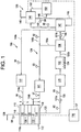
- FIG. 1 illustrates a system 100 for removal of carbon dioxide (CO 2 ) from a gas stream.
- the system 100 includes a columnar absorber 110, wherein a CO 2 -containing gas stream 112, such as, for example, a flue gas stream, is introduced and contacted with a solvent, such as CO 2 -lean stream 114a and/or CO 2 semi-lean stream 114b.
- a CO 2 -containing gas stream 112 such as, for example, a flue gas stream
- the CO 2 -containing gas stream 112 may be contacted with the solvent 114a, 114b in a counter-current manner; however, it is contemplated that the CO 2 -containing gas stream 112 may be contacted with the solvent 114a, 114b in any manner or direction that is desired in the system 100.
- the CO 2 -lean stream 114a and/or CO 2 semi-lean stream 114b are both ammonia-containing solvents that absorb CO 2 from the gas stream 112.
- the solvent 114a, 114b includes a low molarity ammonia having a molarity between about 0.5 molar to about 13 molar.
- the molarity of the ammonia-containing solvent 114a, 114b is between about 0.5 molar to about 6 molar in the absorber 110.
- the ammonia-containing solvent 114a comprises a CO 2 -lean stream and the ammonia-containing solvent 114b comprises a CO 2 semi-lean stream.
- the CO 2 -lean stream 114a comprises a regenerated solvent 149 that is cycled back to the absorber 110 after exiting a regenerator 144 wherein the regenerated solvent 149 is stripped of carbon dioxide.
- the regenerated solvent 149 and thus the CO 2 -lean stream 114a, exhibits lean CO 2 loading ranging from 0.00 to 0.45 moles of CO 2 / moles of ammonia.
- the CO 2 semi-lean stream 114b comprises a stream 120a that is extracted from the separation device 138 and is cycled back to the absorber 110 without passing through the regenerator 144.
- the ammonia-containing solvent, CO 2 -lean stream 114a and/or CO 2 semi-lean stream 114b also includes a catalyst in the form of an enzyme.
- the enzyme is a metalloenzyme, such as, for example, carbonic anhydrase.
- the catalyst is added to the ammonia-containing solvent, CO 2 -lean stream 114a and/or CO 2 semi-lean stream 114b, to increase the total loading of the solution and/or favor the formation of a bicarbonate salt precipitate.
- the absorber 110 is operated at a temperature of about 45°C or less.
- the absorber 110 is operated in accordance with CAP, as described above, such that the temperature of the absorber 110 is about 20°C. It is contemplated that a top section 110a of the absorber 110 could be operated at a temperature of about 10°C or less.
- the gas stream 112 enters a bottom portion 116 of the absorber 110 and travels up a length L of the absorber 110 where it is contacted with the CO 2 semi-lean stream 114b in a first absorption section 118.
- the contact between the CO 2 semi-lean stream 114b and the gas stream 112 forms a stream 120 that is rich in CO 2 and ammonia (NH3), and a stream 122 containing reduced CO 2 .
- NH3 ammonia
- the stream 120 is removed from the absorber 110 and a portion 120a of the stream 120 is recycled to the absorber 110 via a feedback loop 124 and introduced to the absorber 110 as the CO 2 semi-lean stream 114b, while the remaining portion of the stream 120 is provided as CO 2 -enriched phase stream 140 to a regeneration system 126.
- the reduced CO 2 containing gas stream 122 continues to a second absorption section 128, where the reduced CO 2 containing gas stream 122 is contacted with CO 2 -lean stream 114a.
- the second absorption section 1208 more CO 2 is absorbed from the gas stream to form a stream 129 that is substantially reduced in carbon dioxide content.
- the absorber 110 may have more than two absorption sections as illustrated.
- the sections of the absorber 110 comprise more than one separate column or unit.
- the stream 129 may be processed through one or more wash sections 130 in the absorber 110 prior to being emitted from the absorber 110 at an outlet 119.
- the molarity of ammonia present in the wash section 130 is between about 0 molar to about 3 molar.
- the stream 129 having a substantially reduced carbon dioxide content may be subjected to further processing in another portion of the system 100 or may be released to an environment.
- the stream 120 is rich in CO 2 and NH3 as a result of the reaction between the CO 2 in the gas stream 112 and the CO 2 -lean stream 114a and/or CO 2 semi-lean stream 114b in the absorber 110.
- a first pressure of the stream 120 is elevated via a first pump 121A and subsequently the stream 120, having an elevated pressure or a second pressure, is cooled via a chiller 123 and provided to a precipitating means 132.
- the precipitating means 132 is a crystallizer, which forms a precipitate 134.
- the precipitate 134 may be, for example, an ammonium salt.
- the precipitate 134 may be, for example, an ammonium salt, and more particularly ammonium bicarbonate, carbamate and/or carbonate.
- ammonium salt and more particularly ammonium bicarbonate, carbamate and/or carbonate.
- the speciation of the three ammonium salts, bicarbonate, ammonium carbamate and carbonate, in an ammonia solution depends on several variables. It has previously been demonstrated that in an ammonia solution with constant molarity, such as, for example, 1.34mol/L, the speciation of bicarbonate will increase as the total of carbon content of the solution increases. A low molarity, highly-loaded ammonia solution favors the formation of ammonium bicarbonates over carbamates.
- FIG. 2 illustrates that CO 2 capture rates of 85% or above are achieved having an absorber length of 30 meters, shown generally by a first plot 410, when the absorber 110 is run at a temperature of about 20°C.
- a 90% capture rate of CO 2 may be achieved upon the regulation of the temperature of the absorber 110 via a control system 136 in communication with the absorber 110 and the regeneration system 126 ( FIG. 1 ).
- the control system 136 comprises a controller 137 in communication with a plurality of devices 90-99 for measuring and selectively adjusting a plurality of operating parameters such as, for example, temperature, pressure, volumetric flow rate, molarity and mass concentrations of each stream of system 100.
- the devices 90-99 include, for example, sensors or other measurement devices, flow control valves, pumps and other flow control means. Such devices 90-99 are configured to transmit to, and receive from, the controller 137 one or more signals for operation of such devices, and the controller 137 is configured to receive and transmit multiple signals simultaneously, at elevated temperature ranges, and having a resistance to vibration, impact and electrical noise.
- control apparatus 136 is shown and described as comprising a controller 137, the present invention is not limited in this regard as the control apparatus 136 may comprise, for example, a Programmable Logic Controller ("PLC”), a distributed control systems (“DCS”), a computer or any type of microprocessor or like programmable control device having software installed therein, a server connected to one or more programmable devices, or any like controller without departing from the broader aspects of the invention.
- PLC Programmable Logic Controller
- DCS distributed control systems
- computer encompasses desktops, laptops, tablets, handheld mobile devices, mobile phones and the like.
- the first plot 410 and a second plot 411 display the CO 2 capture rate in ammonia at 1.5M as a function of a length "L" of the absorber 110.
- the X axis 400 shows the absorber height L in meters.
- the first Y axis 420 shows % CO 2 capture.
- a second Y axis 440 shows CO 2 concentration at the outlet 119.
- the graph of FIG. 2 illustrates the following data points for plots 410 and 411, as summarized in Tables 1A and 1B below.
- Table 1A provides the CO 2 Capture rate as a function of packing height
- Table 1B provides the CO 2 outlet concentration as a function of packing height.
- the first plot 410 shows CO 2 capture approaching 80% at approximately 20m and approaching 90% at approximately 50m.
- a curve 411 shows the concentration of CO 2 at the outlet of the absorber 110, which approaches 0.01 molar at approximately 40m.
- a stream 120b containing the precipitate 134 is provided to a separation device 138.
- the separation device 138 may be any type or kind of device that is capable of separating solids (e.g., precipitate) from liquid (e.g. stream 120b), including but not limited to the separation device 138 being a cyclone.
- the separation device 138 separates the portion 120a from the stream 120b containing the precipitate 134.
- the portion 120a of the stream 120 is recycled to the absorber 110 via the feedback loop 124.
- the separation device 138 provides a CO 2 -enriched phase or stream 140 to the regeneration system 126.
- a first pressure of the stream 140 is elevated via a second pump 121B and subsequently the stream 140, having an elevated pressure or a second pressure, is passed to the regeneration system 126.
- the CO 2 -enriched phase, stream 140, including the precipitate is provided to the regeneration system 126.
- the ammonia-containing solvent, CO 2 -lean stream 114a and/or CO 2 semi-lean stream 114b includes a catalyst in the form of an enzyme.
- the stream 120 that is removed from the absorber 110, cooled via the chiller 123, provided to the precipitating means 132, and subsequently provided to the separation device 138 as the stream 120b containing the precipitate 134 correspondingly includes the catalyst.
- the separation device 138 separates the portion 120a, including the catalyst, from the stream 120b containing the precipitate 134, and the portion 120a, including the catalyst, is recycled to the absorber 110 via the feedback loop 124.
- the CO 2 -enriched phase stream 140 is provided to a heat exchanger 142 prior to being provided to a regenerator 144.
- the CO 2 -enriched phase stream 140 is stripped of carbon dioxide by breaking the chemical bond between the carbon dioxide and the solvent.
- the carbon dioxide is removed from the solvent by the introduction of heat to the regenerator 144.
- a reboiler 150 is provided to further process a regenerated solvent 149 exiting the regenerator 144.
- the regenerator 144 is operated at a temperature of about 110°C. In another embodiment, the regenerator 144 operates at less than 100°C. It is contemplated that the temperature of the regenerator 144 and the reboiler 150 may be controlled via the control system 136.
- Very high CO 2 loading is achievable when the ammonia-containing solvent 114a, 114b has a molarity between about 0.5 molar and 6 molar and the precipitate 134 is formed. This results in a high partial pressure of CO 2 in the stream 140, which enables regeneration to be conducted at a temperature as low as 115°C.
- a CO 2 rich loading of 0.8 molar has been reached and for a regeneration pressure of 2 bars, simulation shows that for a 90% CO 2 removal, temperatures as low as 115°C are suitable to regenerate the solvent. As the temperature of the regenerator 144 decreases, it is understood that CO 2 removal will be improved during the regeneration process.
- the plot shows the reboiler 150 temperature and lean solution CO 2 loading as a function of regenerator temperature when the ammonia concentration is at 1.5M and the rich loading is 0.8.
- the X axis 500 shows the pressure in the regenerator 144 ranging from 0 bars to 10 bars.
- the first Y axis 520 shows the reboiler 150 temperature in °C ranging from 100°C to 140°C.
- the second Y axis 540 shows lean CO 2 loading in moles of CO 2 / moles of ammonia ranging from 0.00 to 0.45 [mole CO 2 /mole NH3].
- Table 3 illustrates the following data points for a third plot 510 and a fourth plot 511, as summarized in Tables 2A and 2B below.
- Table 2A provides a reboiler temperature as a function of regenerator temperature; and
- Table 2B provides a lean CO 2 loading as a function of regenerator temperature
- the third plot 510 illustrates the reboiler 150 temperature increases as pressure increases, wherein at approximately 2 bars, the reboiler 150 temperature is about 114°C and at approximately 10 bars the reboiler 150 temperature is about 134°C.
- the fourth plot 511 illustrates the lean CO 2 loading increases as pressure increases, wherein at approximately 2 bar, the CO 2 loading is about 0.15 [mole CO 2 /mole NH 3 ] and at approximately 10 bars, the CO 2 loading is about 0.40 [mole CO 2 /mole NH 3 ].
- the carbon dioxide is released from the regenerator 144 as a stream of carbon dioxide 146.
- the stream of carbon dioxide 146 is sent to another section of the system 100 for further processing, storage or use, while the regenerated solvent 149 leaves the regenerator bottom via line 148. At least a portion of the regenerated solvent is passed to the reboiler 150 via the line 148.
- the system 100 may include one or more pumps that facilitate the movement of the regenerated solvent 149 throughout the system.
- the regenerated solvent 149 is boiled to generate vapor 152, which is returned to the regenerator 144 to drive separation of carbon dioxide from the solvent.
- reboiling of the regenerated solvent 149 may provide further carbon dioxide removal from the regenerated solvent 149.
- the regenerated solvent 149 is passed to the heat exchanger 142 for heat-exchanging with the CO 2 -enriched phase stream140. Heat-exchanging allows for heat transfer between the solutions, resulting in a cooled regenerated solvent 149a and the heated CO 2 -enriched phase stream 140.
- the regenerated solvent 149a is thereafter cycled to the next round of absorption in the absorber as the CO 2 -lean stream 114a. It is contemplated that the regenerated solvent 149a may be cooled via one or more chillers 141 prior to being introduced to the absorber 110.
- the regenerated solvent 149a is referred to as a first regenerated solvent 149a; and a second regenerated solvent 149b is extracted from the first regenerated solvent 149a. Thereafter, the second regenerated solvent 149b is cycled together with the portion 120a of the stream 120 to the absorber 110 via the feedback loop 124 as the CO 2 semi-lean stream 114b.
- the controller 137 is configured to measure and selectively adjust the flow rate of at least one of the regenerated solvent 149a and the second regenerated solvent 149b to respectively adjust the CO 2 -content of CO 2 -lean stream 114a and/or the CO 2 semi-lean stream 114b.
- the foregoing system and method provides increased efficiency of carbon dioxide capture and lower ammonia emission.
- Utilization of a lower molarity ammonia-containing solvent permits increased carbon dioxide loading, which reduces the number of wash sections 130 utilized in the absorber 110. Additionally, the utilization of a lower molarity solution will permit the regenerator 144 to operate at a lower pressure and lower temperature, which may contribute to efficiency and cost savings.
- Operating the system 100 at a lower ammonia molarity may reduce ammonia emissions from an absorption section 118, 128 to a wash section 130.
- the absorber 110 may have three absorption sections. It has been demonstrated that as lean solution CO 2 loading increases, for example from about 0.23 to about 0.47, ammonia emissions decrease, for example approximately 35%.
- the lower molarity ammonia-containing solution does not increase the amount of energy required to regenerate the solution 149 in the regenerator 144, and reduces the energy consumption in the absorber 110 because of the lower ammonia emissions from the absorption section to the wash section.
- the carbon dioxide removal efficiency may be reduced when using lower molarity ammonia-containing solvents at the same operating conditions at the same absorber bed height as compared to systems utilizing higher molarity solvents.
- low molarity solvents permit the system to operate at a higher temperature. Operation of the system at a higher temperature may improve kinetics, which in turn increases carbon dioxide capture efficiency. Operation at a higher temperature will also reduce the load needed to cool the absorber 110.
- the various embodiments of the present invention described herein above provide a system and method for precipitating ammonium salts as a means to separate a CO 2 -rich phase from a CO 2 -semi-lean phase and thus reduce the energy requirements during regeneration.
- Such a system and method uses lower molarity ammonia (0.5-6 molar) with minimized ammonia losses to the gas overheads (up to an order of magnitude lower) and provides significant cyclic capacity while maintaining adequate adsorption kinetics in the absorber.
- the process takes advantage of precipitating ammonium salts post absorber and in a controlled manner by cooling the CO 2 -rich solvent, therefore separating a CO 2 -and-ammonia-rich phase, which is sent to the regenerator for an energy-efficient regeneration.
- the semi-lean phase is recirculated to the absorber to be enriched again above its low-temperature saturation point.
- Ammonia plays a dual role of an accelerator of the CO 2 absorption reaction in the liquid phase as well as a precipitating agent for the separation of the CO 2 -rich phase from the CO 2 -semi-lean phase. Since both ammonia and CO 2 are concentrated in the CO 2 -rich phase, their partial pressures are higher and upon heating of the solution, regeneration of CO 2 at higher pressure can take place. Since ammonia is more volatile than water, significant regeneration can take place at relatively lower temperature (100°C or below) and higher pressure. Therefore, the process allows for lower temperature, higher pressure CO 2 regeneration with the ammonia as a main stripping agent.
- the ammonia loss to the gas phase is proportional to the liquid phase free ammonia (non-reacted ammonia) concentration. At lower molarity, the saturation concentration for CO 2 is significantly increased and much higher CO 2 -rich loading can be reached.
Landscapes
- Chemical & Material Sciences (AREA)
- Engineering & Computer Science (AREA)
- Analytical Chemistry (AREA)
- General Chemical & Material Sciences (AREA)
- Oil, Petroleum & Natural Gas (AREA)
- Chemical Kinetics & Catalysis (AREA)
- Health & Medical Sciences (AREA)
- Biomedical Technology (AREA)
- Environmental & Geological Engineering (AREA)
- Life Sciences & Earth Sciences (AREA)
- Sustainable Development (AREA)
- Gas Separation By Absorption (AREA)
- Treating Waste Gases (AREA)
Claims (11)
- Procédé pour l'élimination de dioxyde de carbone d'un gaz (112), le procédé comprenant :l'introduction d'un flux de gaz contenant du dioxyde de carbone (112) à une portion inférieure (116) d'un absorbeur (110) ;la mise en contact du flux de gaz avec un solvant contenant de l'ammoniaque (114a, 114b) sous la forme d'un flux pauvre en CO2 (114a) et d'un flux semi-pauvre en CO2 (114b), le solvant contenant de l'ammoniaque présentant une molarité entre 0,5 mole et 13 moles ; etl'absorption du dioxyde de carbone du flux de gaz (112) avec le solvant contenant de l'ammoniaque (114a, 114b), en éliminant de ce fait le dioxyde de carbone du flux de gaz (112) et en formant un flux riche en CO2 (120), dans lequel le flux de gaz contenant du dioxyde de carbone (112) se déplace vers le haut d'une longueur (L) de l'absorbeur (110) lorsqu'il est mis en contact avec le flux semi-pauvre en CO2 (114b) dans une première section d'absorption (118) et un flux de gaz contenant une quantité réduite de CO2 (122) continue jusqu'à une deuxième section d'absorption (128), où le flux de gaz contenant une quantité réduite de CO2 (122) est mis en contact avec le flux pauvre en CO2 (114a) ;le passage du flux riche en CO2 (120) à un moyen de précipitation (132) pour former un précipité dans le flux enrichi en CO2 puis le passage de celui-ci à un dispositif de séparation (138) ;la séparation d'une portion (120a) du flux riche en CO2 (120) dans le moyen de séparation (138) et le recyclage de cette portion (120a) par l'intermédiaire d'une boucle de rétroaction (124) à l'absorbeur (110) et l'introduction de celle-ci dans l'absorbeur (110) en tant que le flux semi-pauvre en CO2 (114b), alors que la portion restante du flux riche en CO2 (120) contenant le précipité (134) est fournie en tant qu'un flux de phase enrichie en CO2 (140) à un système de régénération (126),le dépouillement du flux enrichi en CO2 (140) du CO2 dans le système de régénération (126) et la circulation du solvant régénéré (149) de retour vers l'absorbeur (110).
- Procédé pour l'élimination de dioxyde de carbone d'un gaz selon la revendication 1, dans lequel le solvant contenant de l'ammoniaque comprend une molarité d'environ 1,5 mole.
- Procédé pour l'élimination de dioxyde de carbone d'un gaz selon la revendication 1, dans lequel l'absorbeur est actionné à une température inférieure ou égale à 45 °C.
- Procédé pour l'élimination de dioxyde de carbone d'un gaz selon la revendication 3, dans lequel l'absorbeur (110) est actionné à une température d'environ 20 °C.
- Procédé pour l'élimination de dioxyde de carbone d'un gaz selon la revendication 1, dans lequel le flux pauvre en CO2 (114a) et/ou le flux semi-pauvre en CO2 (114b) comprennent en outre un catalyseur sous la forme d'une enzyme.
- Procédé pour l'élimination de dioxyde de carbone d'un gaz selon la revendication 5, comprenant l'étape de refroidissement du flux riche en CO2 (120) dans un refroidisseur (123) avant le passage de celui-ci au moyen de précipitation (132), dans lequel la portion (120a) du flux riche en CO2 (120) qui est recyclée de retour vers l'absorbeur (110) inclut le catalyseur.
- Procédé pour l'élimination de dioxyde de carbone d'un gaz selon la revendication 1 ou 5, comprenant l'étape de la fourniture du flux enrichi en CO2 (140) à un échangeur de chaleur (142) pour le chauffer avant de le fournir au régénérateur (144) et la fourniture du solvant régénéré (149) à l'échangeur de chaleur (142) pour échanger la chaleur avec le flux enrichi en CO2 (140) avant de le faire circuler de retour vers l'absorbeur (110).
- Procédé pour l'élimination de dioxyde de carbone d'un gaz selon la revendication 1, comprenant en outre l'élimination du flux riche en CO2 (120) de l'absorbeur et la formation d'un précipité dans le flux riche en CO2 (120).
- Procédé pour l'élimination de dioxyde de carbone d'un gaz selon la revendication 8, dans lequel le précipité est un sel d'ammonium.
- Procédé pour l'élimination de dioxyde de carbone d'un gaz selon la revendication 1, comprenant en outre :
la fourniture de la phase enrichie en CO2 (140) au système de régénération (126) pour séparer le dioxyde de carbone du solvant contenant de l'ammoniaque afin de former un flux de dioxyde de carbone (146) et un solvant régénéré (149). - Procédé pour l'élimination de dioxyde de carbone d'un gaz selon la revendication 10, comprenant en outre :
la fourniture du solvant régénéré (149) à l'absorbeur (110) en tant qu'un flux pauvre en CO2 (114a).
Applications Claiming Priority (3)
| Application Number | Priority Date | Filing Date | Title |
|---|---|---|---|
| US201261617720P | 2012-03-30 | 2012-03-30 | |
| US13/834,718 US20130259785A1 (en) | 2012-03-30 | 2013-03-15 | Method and system for carbon dioxide removal |
| PCT/IB2013/052475 WO2013144890A2 (fr) | 2012-03-30 | 2013-03-27 | Procédé et système pour une élimination de dioxyde de carbone |
Publications (2)
| Publication Number | Publication Date |
|---|---|
| EP2830739A2 EP2830739A2 (fr) | 2015-02-04 |
| EP2830739B1 true EP2830739B1 (fr) | 2019-01-23 |
Family
ID=49235323
Family Applications (1)
| Application Number | Title | Priority Date | Filing Date |
|---|---|---|---|
| EP13722098.4A Active EP2830739B1 (fr) | 2012-03-30 | 2013-03-27 | Procédé pour l'élimination de dioxyde de carbone avec solution contenant de l'ammoniaque |
Country Status (6)
| Country | Link |
|---|---|
| US (1) | US20130259785A1 (fr) |
| EP (1) | EP2830739B1 (fr) |
| CN (1) | CN105431222A (fr) |
| AU (1) | AU2013239088A1 (fr) |
| CA (1) | CA2867666C (fr) |
| WO (1) | WO2013144890A2 (fr) |
Families Citing this family (2)
| Publication number | Priority date | Publication date | Assignee | Title |
|---|---|---|---|---|
| US10322367B2 (en) | 2016-02-12 | 2019-06-18 | University Of Kentucky Research Foundation | Method of development and use of catalyst-functionalized catalytic particles to increase the mass transfer rate of solvents used in acid gas cleanup |
| US10427948B2 (en) * | 2018-01-26 | 2019-10-01 | Ethan J. Novek | Systems and methods for ammonia recovery, acid gas separation, or combination thereof |
Citations (1)
| Publication number | Priority date | Publication date | Assignee | Title |
|---|---|---|---|---|
| US20110061533A1 (en) * | 2009-09-15 | 2011-03-17 | Black Sean E | Method and system for removal of carbon dioxide from a process gas |
Family Cites Families (8)
| Publication number | Priority date | Publication date | Assignee | Title |
|---|---|---|---|---|
| CA2672641C (fr) * | 2006-12-15 | 2014-07-08 | Sinvent As | Procede de capture du co<sb>2</sb> a partir d'un gaz d'echappement |
| US7981196B2 (en) * | 2007-06-04 | 2011-07-19 | Posco | Apparatus and method for recovering carbon dioxide from flue gas using ammonia water |
| US20100267123A1 (en) * | 2007-06-22 | 2010-10-21 | Louis Wibberley | Method for co2 transfer from gas streams to ammonia solutions |
| AU2009307050A1 (en) * | 2008-10-23 | 2010-04-29 | Commonwealth Scientific & Industrial Research Organisation | Use of enzyme catalysts in CO2 PCC processes |
| EP3828185B1 (fr) * | 2009-01-06 | 2024-11-20 | Dana-Farber Cancer Institute, Inc. | Composés d'échafaudage de kinase pyrimido-diazépinone et procédés de traitement de troubles |
| US8790605B2 (en) * | 2009-09-15 | 2014-07-29 | Alstom Technology Ltd | Method for removal of carbon dioxide from a process gas |
| US8328911B2 (en) * | 2010-06-21 | 2012-12-11 | The University Of Kentucky Research Foundation | Method for removing CO2 from coal-fired power plant flue gas using ammonia as the scrubbing solution, with a chemical additive for reducing NH3 losses, coupled with a membrane for concentrating the CO2 stream to the gas stripper |
| US8623307B2 (en) * | 2010-09-14 | 2014-01-07 | Alstom Technology Ltd. | Process gas treatment system |
-
2013
- 2013-03-15 US US13/834,718 patent/US20130259785A1/en not_active Abandoned
- 2013-03-27 EP EP13722098.4A patent/EP2830739B1/fr active Active
- 2013-03-27 WO PCT/IB2013/052475 patent/WO2013144890A2/fr not_active Ceased
- 2013-03-27 AU AU2013239088A patent/AU2013239088A1/en not_active Abandoned
- 2013-03-27 CA CA2867666A patent/CA2867666C/fr active Active
- 2013-03-27 CN CN201380017717.0A patent/CN105431222A/zh active Pending
Patent Citations (1)
| Publication number | Priority date | Publication date | Assignee | Title |
|---|---|---|---|---|
| US20110061533A1 (en) * | 2009-09-15 | 2011-03-17 | Black Sean E | Method and system for removal of carbon dioxide from a process gas |
Also Published As
| Publication number | Publication date |
|---|---|
| EP2830739A2 (fr) | 2015-02-04 |
| WO2013144890A2 (fr) | 2013-10-03 |
| CN105431222A (zh) | 2016-03-23 |
| WO2013144890A3 (fr) | 2016-10-06 |
| US20130259785A1 (en) | 2013-10-03 |
| AU2013239088A1 (en) | 2014-09-25 |
| CA2867666C (fr) | 2020-09-22 |
| CA2867666A1 (fr) | 2013-10-03 |
Similar Documents
| Publication | Publication Date | Title |
|---|---|---|
| EP2175967B1 (fr) | Procede ameliore de transfert de co2 de flux gazeux vers des solutions ammoniacales | |
| JP5663479B2 (ja) | Co2枯渇煙道ガスの処理 | |
| EP2523742B1 (fr) | Procédé de lavage à l'eau pour un procédé de capture de dioxyde de carbone | |
| KR101297210B1 (ko) | 암모니아수 흡수용액을 사용하는 개선된 이산화탄소 포집 방법 및 이를 구현하는 장치 | |
| EP2928822B1 (fr) | Amélioration de la vitesse d'absorption de co2 dans des solutions aqueuses de carbonate de potassium et d'ammoniaque | |
| CN103582518B (zh) | 二氧化碳捕集系统 | |
| KR20130056330A (ko) | 연도 가스로부터 co₂ 포집을 위한 용제 및 방법 | |
| US20140105800A1 (en) | Method for processing a power plant flue gas | |
| US20130260442A1 (en) | Carbon dioxide capture process with catalytically-enhanced solvent and phase separation | |
| US9573816B2 (en) | System for low pressure carbon dioxide regeneration in a chilled ammonia process | |
| US20100135881A1 (en) | Process for simultaneous removal of carbon dioxide and sulfur oxides from flue gas | |
| EP2830739B1 (fr) | Procédé pour l'élimination de dioxyde de carbone avec solution contenant de l'ammoniaque | |
| US20120251421A1 (en) | Processes for reducing nitrosamine formation during gas purification in amine based liquid absorption systems | |
| KR20180013324A (ko) | 흡수제의 손실을 저감하는, 흡수제의 다단공급을 통한 이산화탄소 포집공정 |
Legal Events
| Date | Code | Title | Description |
|---|---|---|---|
| PUAI | Public reference made under article 153(3) epc to a published international application that has entered the european phase |
Free format text: ORIGINAL CODE: 0009012 |
|
| 17P | Request for examination filed |
Effective date: 20141007 |
|
| AK | Designated contracting states |
Kind code of ref document: A2 Designated state(s): AL AT BE BG CH CY CZ DE DK EE ES FI FR GB GR HR HU IE IS IT LI LT LU LV MC MK MT NL NO PL PT RO RS SE SI SK SM TR |
|
| AX | Request for extension of the european patent |
Extension state: BA ME |
|
| RIN1 | Information on inventor provided before grant (corrected) |
Inventor name: VITSE, FREDERIC Inventor name: HIWALE, RAMESHWAR SHAMRAO Inventor name: VERSTEEG, GEERT |
|
| DAX | Request for extension of the european patent (deleted) | ||
| RAP1 | Party data changed (applicant data changed or rights of an application transferred) |
Owner name: GENERAL ELECTRIC TECHNOLOGY GMBH |
|
| R17D | Deferred search report published (corrected) |
Effective date: 20161006 |
|
| STAA | Information on the status of an ep patent application or granted ep patent |
Free format text: STATUS: EXAMINATION IS IN PROGRESS |
|
| 17Q | First examination report despatched |
Effective date: 20171011 |
|
| GRAP | Despatch of communication of intention to grant a patent |
Free format text: ORIGINAL CODE: EPIDOSNIGR1 |
|
| STAA | Information on the status of an ep patent application or granted ep patent |
Free format text: STATUS: GRANT OF PATENT IS INTENDED |
|
| INTG | Intention to grant announced |
Effective date: 20180817 |
|
| GRAS | Grant fee paid |
Free format text: ORIGINAL CODE: EPIDOSNIGR3 |
|
| GRAA | (expected) grant |
Free format text: ORIGINAL CODE: 0009210 |
|
| STAA | Information on the status of an ep patent application or granted ep patent |
Free format text: STATUS: THE PATENT HAS BEEN GRANTED |
|
| AK | Designated contracting states |
Kind code of ref document: B1 Designated state(s): AL AT BE BG CH CY CZ DE DK EE ES FI FR GB GR HR HU IE IS IT LI LT LU LV MC MK MT NL NO PL PT RO RS SE SI SK SM TR |
|
| REG | Reference to a national code |
Ref country code: GB Ref legal event code: FG4D |
|
| REG | Reference to a national code |
Ref country code: CH Ref legal event code: EP |
|
| REG | Reference to a national code |
Ref country code: AT Ref legal event code: REF Ref document number: 1090991 Country of ref document: AT Kind code of ref document: T Effective date: 20190215 |
|
| REG | Reference to a national code |
Ref country code: IE Ref legal event code: FG4D |
|
| REG | Reference to a national code |
Ref country code: DE Ref legal event code: R096 Ref document number: 602013050190 Country of ref document: DE |
|
| REG | Reference to a national code |
Ref country code: NL Ref legal event code: MP Effective date: 20190123 |
|
| REG | Reference to a national code |
Ref country code: NO Ref legal event code: T2 Effective date: 20190123 |
|
| PG25 | Lapsed in a contracting state [announced via postgrant information from national office to epo] |
Ref country code: NL Free format text: LAPSE BECAUSE OF FAILURE TO SUBMIT A TRANSLATION OF THE DESCRIPTION OR TO PAY THE FEE WITHIN THE PRESCRIBED TIME-LIMIT Effective date: 20190123 |
|
| PG25 | Lapsed in a contracting state [announced via postgrant information from national office to epo] |
Ref country code: FI Free format text: LAPSE BECAUSE OF FAILURE TO SUBMIT A TRANSLATION OF THE DESCRIPTION OR TO PAY THE FEE WITHIN THE PRESCRIBED TIME-LIMIT Effective date: 20190123 Ref country code: SE Free format text: LAPSE BECAUSE OF FAILURE TO SUBMIT A TRANSLATION OF THE DESCRIPTION OR TO PAY THE FEE WITHIN THE PRESCRIBED TIME-LIMIT Effective date: 20190123 Ref country code: PT Free format text: LAPSE BECAUSE OF FAILURE TO SUBMIT A TRANSLATION OF THE DESCRIPTION OR TO PAY THE FEE WITHIN THE PRESCRIBED TIME-LIMIT Effective date: 20190523 Ref country code: PL Free format text: LAPSE BECAUSE OF FAILURE TO SUBMIT A TRANSLATION OF THE DESCRIPTION OR TO PAY THE FEE WITHIN THE PRESCRIBED TIME-LIMIT Effective date: 20190123 Ref country code: LT Free format text: LAPSE BECAUSE OF FAILURE TO SUBMIT A TRANSLATION OF THE DESCRIPTION OR TO PAY THE FEE WITHIN THE PRESCRIBED TIME-LIMIT Effective date: 20190123 Ref country code: ES Free format text: LAPSE BECAUSE OF FAILURE TO SUBMIT A TRANSLATION OF THE DESCRIPTION OR TO PAY THE FEE WITHIN THE PRESCRIBED TIME-LIMIT Effective date: 20190123 |
|
| REG | Reference to a national code |
Ref country code: AT Ref legal event code: MK05 Ref document number: 1090991 Country of ref document: AT Kind code of ref document: T Effective date: 20190123 |
|
| PG25 | Lapsed in a contracting state [announced via postgrant information from national office to epo] |
Ref country code: RS Free format text: LAPSE BECAUSE OF FAILURE TO SUBMIT A TRANSLATION OF THE DESCRIPTION OR TO PAY THE FEE WITHIN THE PRESCRIBED TIME-LIMIT Effective date: 20190123 Ref country code: HR Free format text: LAPSE BECAUSE OF FAILURE TO SUBMIT A TRANSLATION OF THE DESCRIPTION OR TO PAY THE FEE WITHIN THE PRESCRIBED TIME-LIMIT Effective date: 20190123 Ref country code: LV Free format text: LAPSE BECAUSE OF FAILURE TO SUBMIT A TRANSLATION OF THE DESCRIPTION OR TO PAY THE FEE WITHIN THE PRESCRIBED TIME-LIMIT Effective date: 20190123 Ref country code: GR Free format text: LAPSE BECAUSE OF FAILURE TO SUBMIT A TRANSLATION OF THE DESCRIPTION OR TO PAY THE FEE WITHIN THE PRESCRIBED TIME-LIMIT Effective date: 20190424 Ref country code: IS Free format text: LAPSE BECAUSE OF FAILURE TO SUBMIT A TRANSLATION OF THE DESCRIPTION OR TO PAY THE FEE WITHIN THE PRESCRIBED TIME-LIMIT Effective date: 20190523 Ref country code: BG Free format text: LAPSE BECAUSE OF FAILURE TO SUBMIT A TRANSLATION OF THE DESCRIPTION OR TO PAY THE FEE WITHIN THE PRESCRIBED TIME-LIMIT Effective date: 20190423 |
|
| REG | Reference to a national code |
Ref country code: DE Ref legal event code: R097 Ref document number: 602013050190 Country of ref document: DE |
|
| PG25 | Lapsed in a contracting state [announced via postgrant information from national office to epo] |
Ref country code: EE Free format text: LAPSE BECAUSE OF FAILURE TO SUBMIT A TRANSLATION OF THE DESCRIPTION OR TO PAY THE FEE WITHIN THE PRESCRIBED TIME-LIMIT Effective date: 20190123 Ref country code: DK Free format text: LAPSE BECAUSE OF FAILURE TO SUBMIT A TRANSLATION OF THE DESCRIPTION OR TO PAY THE FEE WITHIN THE PRESCRIBED TIME-LIMIT Effective date: 20190123 Ref country code: CZ Free format text: LAPSE BECAUSE OF FAILURE TO SUBMIT A TRANSLATION OF THE DESCRIPTION OR TO PAY THE FEE WITHIN THE PRESCRIBED TIME-LIMIT Effective date: 20190123 Ref country code: RO Free format text: LAPSE BECAUSE OF FAILURE TO SUBMIT A TRANSLATION OF THE DESCRIPTION OR TO PAY THE FEE WITHIN THE PRESCRIBED TIME-LIMIT Effective date: 20190123 Ref country code: IT Free format text: LAPSE BECAUSE OF FAILURE TO SUBMIT A TRANSLATION OF THE DESCRIPTION OR TO PAY THE FEE WITHIN THE PRESCRIBED TIME-LIMIT Effective date: 20190123 Ref country code: SK Free format text: LAPSE BECAUSE OF FAILURE TO SUBMIT A TRANSLATION OF THE DESCRIPTION OR TO PAY THE FEE WITHIN THE PRESCRIBED TIME-LIMIT Effective date: 20190123 Ref country code: AL Free format text: LAPSE BECAUSE OF FAILURE TO SUBMIT A TRANSLATION OF THE DESCRIPTION OR TO PAY THE FEE WITHIN THE PRESCRIBED TIME-LIMIT Effective date: 20190123 Ref country code: MC Free format text: LAPSE BECAUSE OF FAILURE TO SUBMIT A TRANSLATION OF THE DESCRIPTION OR TO PAY THE FEE WITHIN THE PRESCRIBED TIME-LIMIT Effective date: 20190123 |
|
| REG | Reference to a national code |
Ref country code: CH Ref legal event code: PL |
|
| PG25 | Lapsed in a contracting state [announced via postgrant information from national office to epo] |
Ref country code: SM Free format text: LAPSE BECAUSE OF FAILURE TO SUBMIT A TRANSLATION OF THE DESCRIPTION OR TO PAY THE FEE WITHIN THE PRESCRIBED TIME-LIMIT Effective date: 20190123 Ref country code: LU Free format text: LAPSE BECAUSE OF NON-PAYMENT OF DUE FEES Effective date: 20190327 |
|
| PLBE | No opposition filed within time limit |
Free format text: ORIGINAL CODE: 0009261 |
|
| REG | Reference to a national code |
Ref country code: BE Ref legal event code: MM Effective date: 20190331 |
|
| STAA | Information on the status of an ep patent application or granted ep patent |
Free format text: STATUS: NO OPPOSITION FILED WITHIN TIME LIMIT |
|
| GBPC | Gb: european patent ceased through non-payment of renewal fee |
Effective date: 20190423 |
|
| PG25 | Lapsed in a contracting state [announced via postgrant information from national office to epo] |
Ref country code: AT Free format text: LAPSE BECAUSE OF FAILURE TO SUBMIT A TRANSLATION OF THE DESCRIPTION OR TO PAY THE FEE WITHIN THE PRESCRIBED TIME-LIMIT Effective date: 20190123 |
|
| 26N | No opposition filed |
Effective date: 20191024 |
|
| PG25 | Lapsed in a contracting state [announced via postgrant information from national office to epo] |
Ref country code: LI Free format text: LAPSE BECAUSE OF NON-PAYMENT OF DUE FEES Effective date: 20190331 Ref country code: GB Free format text: LAPSE BECAUSE OF NON-PAYMENT OF DUE FEES Effective date: 20190423 Ref country code: IE Free format text: LAPSE BECAUSE OF NON-PAYMENT OF DUE FEES Effective date: 20190327 Ref country code: CH Free format text: LAPSE BECAUSE OF NON-PAYMENT OF DUE FEES Effective date: 20190331 |
|
| PG25 | Lapsed in a contracting state [announced via postgrant information from national office to epo] |
Ref country code: BE Free format text: LAPSE BECAUSE OF NON-PAYMENT OF DUE FEES Effective date: 20190331 Ref country code: FR Free format text: LAPSE BECAUSE OF NON-PAYMENT OF DUE FEES Effective date: 20190331 Ref country code: SI Free format text: LAPSE BECAUSE OF FAILURE TO SUBMIT A TRANSLATION OF THE DESCRIPTION OR TO PAY THE FEE WITHIN THE PRESCRIBED TIME-LIMIT Effective date: 20190123 |
|
| PG25 | Lapsed in a contracting state [announced via postgrant information from national office to epo] |
Ref country code: TR Free format text: LAPSE BECAUSE OF FAILURE TO SUBMIT A TRANSLATION OF THE DESCRIPTION OR TO PAY THE FEE WITHIN THE PRESCRIBED TIME-LIMIT Effective date: 20190123 |
|
| PG25 | Lapsed in a contracting state [announced via postgrant information from national office to epo] |
Ref country code: MT Free format text: LAPSE BECAUSE OF NON-PAYMENT OF DUE FEES Effective date: 20190327 |
|
| PG25 | Lapsed in a contracting state [announced via postgrant information from national office to epo] |
Ref country code: CY Free format text: LAPSE BECAUSE OF FAILURE TO SUBMIT A TRANSLATION OF THE DESCRIPTION OR TO PAY THE FEE WITHIN THE PRESCRIBED TIME-LIMIT Effective date: 20190123 |
|
| PG25 | Lapsed in a contracting state [announced via postgrant information from national office to epo] |
Ref country code: HU Free format text: LAPSE BECAUSE OF FAILURE TO SUBMIT A TRANSLATION OF THE DESCRIPTION OR TO PAY THE FEE WITHIN THE PRESCRIBED TIME-LIMIT; INVALID AB INITIO Effective date: 20130327 |
|
| PG25 | Lapsed in a contracting state [announced via postgrant information from national office to epo] |
Ref country code: MK Free format text: LAPSE BECAUSE OF FAILURE TO SUBMIT A TRANSLATION OF THE DESCRIPTION OR TO PAY THE FEE WITHIN THE PRESCRIBED TIME-LIMIT Effective date: 20190123 |
|
| PGFP | Annual fee paid to national office [announced via postgrant information from national office to epo] |
Ref country code: DE Payment date: 20250218 Year of fee payment: 13 |
|
| PGFP | Annual fee paid to national office [announced via postgrant information from national office to epo] |
Ref country code: NO Payment date: 20250219 Year of fee payment: 13 |