EP2830908B1 - Betrieb eines stromrichters an einem fahrweg von landfahrzeugen oder an einer parklücke eines landfahrzeugs - Google Patents
Betrieb eines stromrichters an einem fahrweg von landfahrzeugen oder an einer parklücke eines landfahrzeugs Download PDFInfo
- Publication number
- EP2830908B1 EP2830908B1 EP13712222.2A EP13712222A EP2830908B1 EP 2830908 B1 EP2830908 B1 EP 2830908B1 EP 13712222 A EP13712222 A EP 13712222A EP 2830908 B1 EP2830908 B1 EP 2830908B1
- Authority
- EP
- European Patent Office
- Prior art keywords
- pole
- supporting structure
- converter
- heat
- conduct
- Prior art date
- Legal status (The legal status is an assumption and is not a legal conclusion. Google has not performed a legal analysis and makes no representation as to the accuracy of the status listed.)
- Not-in-force
Links
- 238000001816 cooling Methods 0.000 claims description 71
- 239000003570 air Substances 0.000 claims description 51
- 239000006163 transport media Substances 0.000 claims description 33
- 239000000463 material Substances 0.000 claims description 12
- 238000000034 method Methods 0.000 claims description 10
- 239000012080 ambient air Substances 0.000 claims description 5
- 239000002609 medium Substances 0.000 description 6
- 230000011664 signaling Effects 0.000 description 5
- 239000007788 liquid Substances 0.000 description 4
- 229910052751 metal Inorganic materials 0.000 description 4
- 239000002184 metal Substances 0.000 description 4
- 229910052782 aluminium Inorganic materials 0.000 description 2
- XAGFODPZIPBFFR-UHFFFAOYSA-N aluminium Chemical compound [Al] XAGFODPZIPBFFR-UHFFFAOYSA-N 0.000 description 2
- 239000012530 fluid Substances 0.000 description 2
- 230000006698 induction Effects 0.000 description 2
- 239000004065 semiconductor Substances 0.000 description 2
- 239000004411 aluminium Substances 0.000 description 1
- 230000033228 biological regulation Effects 0.000 description 1
- 239000004020 conductor Substances 0.000 description 1
- 238000010276 construction Methods 0.000 description 1
- 230000005672 electromagnetic field Effects 0.000 description 1
- 238000001125 extrusion Methods 0.000 description 1
- 238000009413 insulation Methods 0.000 description 1
- 239000000203 mixture Substances 0.000 description 1
- 239000002245 particle Substances 0.000 description 1
- 239000011814 protection agent Substances 0.000 description 1
- XLYOFNOQVPJJNP-UHFFFAOYSA-N water Substances O XLYOFNOQVPJJNP-UHFFFAOYSA-N 0.000 description 1
Images

Classifications
-
- B—PERFORMING OPERATIONS; TRANSPORTING
- B60—VEHICLES IN GENERAL
- B60L—PROPULSION OF ELECTRICALLY-PROPELLED VEHICLES; SUPPLYING ELECTRIC POWER FOR AUXILIARY EQUIPMENT OF ELECTRICALLY-PROPELLED VEHICLES; ELECTRODYNAMIC BRAKE SYSTEMS FOR VEHICLES IN GENERAL; MAGNETIC SUSPENSION OR LEVITATION FOR VEHICLES; MONITORING OPERATING VARIABLES OF ELECTRICALLY-PROPELLED VEHICLES; ELECTRIC SAFETY DEVICES FOR ELECTRICALLY-PROPELLED VEHICLES
- B60L53/00—Methods of charging batteries, specially adapted for electric vehicles; Charging stations or on-board charging equipment therefor; Exchange of energy storage elements in electric vehicles
- B60L53/20—Methods of charging batteries, specially adapted for electric vehicles; Charging stations or on-board charging equipment therefor; Exchange of energy storage elements in electric vehicles characterised by converters located in the vehicle
- B60L53/22—Constructional details or arrangements of charging converters specially adapted for charging electric vehicles
-
- H—ELECTRICITY
- H05—ELECTRIC TECHNIQUES NOT OTHERWISE PROVIDED FOR
- H05K—PRINTED CIRCUITS; CASINGS OR CONSTRUCTIONAL DETAILS OF ELECTRIC APPARATUS; MANUFACTURE OF ASSEMBLAGES OF ELECTRICAL COMPONENTS
- H05K7/00—Constructional details common to different types of electric apparatus
- H05K7/20—Modifications to facilitate cooling, ventilating, or heating
- H05K7/2089—Modifications to facilitate cooling, ventilating, or heating for power electronics, e.g. for inverters for controlling motor
- H05K7/20909—Forced ventilation, e.g. on heat dissipaters coupled to components
-
- B—PERFORMING OPERATIONS; TRANSPORTING
- B60—VEHICLES IN GENERAL
- B60L—PROPULSION OF ELECTRICALLY-PROPELLED VEHICLES; SUPPLYING ELECTRIC POWER FOR AUXILIARY EQUIPMENT OF ELECTRICALLY-PROPELLED VEHICLES; ELECTRODYNAMIC BRAKE SYSTEMS FOR VEHICLES IN GENERAL; MAGNETIC SUSPENSION OR LEVITATION FOR VEHICLES; MONITORING OPERATING VARIABLES OF ELECTRICALLY-PROPELLED VEHICLES; ELECTRIC SAFETY DEVICES FOR ELECTRICALLY-PROPELLED VEHICLES
- B60L53/00—Methods of charging batteries, specially adapted for electric vehicles; Charging stations or on-board charging equipment therefor; Exchange of energy storage elements in electric vehicles
- B60L53/10—Methods of charging batteries, specially adapted for electric vehicles; Charging stations or on-board charging equipment therefor; Exchange of energy storage elements in electric vehicles characterised by the energy transfer between the charging station and the vehicle
- B60L53/12—Inductive energy transfer
-
- B—PERFORMING OPERATIONS; TRANSPORTING
- B60—VEHICLES IN GENERAL
- B60L—PROPULSION OF ELECTRICALLY-PROPELLED VEHICLES; SUPPLYING ELECTRIC POWER FOR AUXILIARY EQUIPMENT OF ELECTRICALLY-PROPELLED VEHICLES; ELECTRODYNAMIC BRAKE SYSTEMS FOR VEHICLES IN GENERAL; MAGNETIC SUSPENSION OR LEVITATION FOR VEHICLES; MONITORING OPERATING VARIABLES OF ELECTRICALLY-PROPELLED VEHICLES; ELECTRIC SAFETY DEVICES FOR ELECTRICALLY-PROPELLED VEHICLES
- B60L53/00—Methods of charging batteries, specially adapted for electric vehicles; Charging stations or on-board charging equipment therefor; Exchange of energy storage elements in electric vehicles
- B60L53/30—Constructional details of charging stations
- B60L53/31—Charging columns specially adapted for electric vehicles
-
- H02J7/022—
-
- H02J7/025—
-
- H—ELECTRICITY
- H02—GENERATION; CONVERSION OR DISTRIBUTION OF ELECTRIC POWER
- H02M—APPARATUS FOR CONVERSION BETWEEN AC AND AC, BETWEEN AC AND DC, OR BETWEEN DC AND DC, AND FOR USE WITH MAINS OR SIMILAR POWER SUPPLY SYSTEMS; CONVERSION OF DC OR AC INPUT POWER INTO SURGE OUTPUT POWER; CONTROL OR REGULATION THEREOF
- H02M7/00—Conversion of AC power input into DC power output; Conversion of DC power input into AC power output
- H02M7/003—Constructional details, e.g. physical layout, assembly, wiring or busbar connections
-
- H—ELECTRICITY
- H05—ELECTRIC TECHNIQUES NOT OTHERWISE PROVIDED FOR
- H05K—PRINTED CIRCUITS; CASINGS OR CONSTRUCTIONAL DETAILS OF ELECTRIC APPARATUS; MANUFACTURE OF ASSEMBLAGES OF ELECTRICAL COMPONENTS
- H05K7/00—Constructional details common to different types of electric apparatus
- H05K7/20—Modifications to facilitate cooling, ventilating, or heating
- H05K7/2089—Modifications to facilitate cooling, ventilating, or heating for power electronics, e.g. for inverters for controlling motor
- H05K7/20927—Liquid coolant without phase change
-
- B—PERFORMING OPERATIONS; TRANSPORTING
- B60—VEHICLES IN GENERAL
- B60L—PROPULSION OF ELECTRICALLY-PROPELLED VEHICLES; SUPPLYING ELECTRIC POWER FOR AUXILIARY EQUIPMENT OF ELECTRICALLY-PROPELLED VEHICLES; ELECTRODYNAMIC BRAKE SYSTEMS FOR VEHICLES IN GENERAL; MAGNETIC SUSPENSION OR LEVITATION FOR VEHICLES; MONITORING OPERATING VARIABLES OF ELECTRICALLY-PROPELLED VEHICLES; ELECTRIC SAFETY DEVICES FOR ELECTRICALLY-PROPELLED VEHICLES
- B60L5/00—Current collectors for power supply lines of electrically-propelled vehicles
-
- B—PERFORMING OPERATIONS; TRANSPORTING
- B60—VEHICLES IN GENERAL
- B60L—PROPULSION OF ELECTRICALLY-PROPELLED VEHICLES; SUPPLYING ELECTRIC POWER FOR AUXILIARY EQUIPMENT OF ELECTRICALLY-PROPELLED VEHICLES; ELECTRODYNAMIC BRAKE SYSTEMS FOR VEHICLES IN GENERAL; MAGNETIC SUSPENSION OR LEVITATION FOR VEHICLES; MONITORING OPERATING VARIABLES OF ELECTRICALLY-PROPELLED VEHICLES; ELECTRIC SAFETY DEVICES FOR ELECTRICALLY-PROPELLED VEHICLES
- B60L53/00—Methods of charging batteries, specially adapted for electric vehicles; Charging stations or on-board charging equipment therefor; Exchange of energy storage elements in electric vehicles
- B60L53/30—Constructional details of charging stations
- B60L53/35—Means for automatic or assisted adjustment of the relative position of charging devices and vehicles
- B60L53/37—Means for automatic or assisted adjustment of the relative position of charging devices and vehicles using optical position determination, e.g. using cameras
-
- B—PERFORMING OPERATIONS; TRANSPORTING
- B60—VEHICLES IN GENERAL
- B60M—POWER SUPPLY LINES, AND DEVICES ALONG RAILS, FOR ELECTRICALLY- PROPELLED VEHICLES
- B60M1/00—Power supply lines for contact with collector on vehicle
- B60M1/30—Power rails
- B60M1/34—Power rails in slotted conduits
-
- Y—GENERAL TAGGING OF NEW TECHNOLOGICAL DEVELOPMENTS; GENERAL TAGGING OF CROSS-SECTIONAL TECHNOLOGIES SPANNING OVER SEVERAL SECTIONS OF THE IPC; TECHNICAL SUBJECTS COVERED BY FORMER USPC CROSS-REFERENCE ART COLLECTIONS [XRACs] AND DIGESTS
- Y02—TECHNOLOGIES OR APPLICATIONS FOR MITIGATION OR ADAPTATION AGAINST CLIMATE CHANGE
- Y02T—CLIMATE CHANGE MITIGATION TECHNOLOGIES RELATED TO TRANSPORTATION
- Y02T10/00—Road transport of goods or passengers
- Y02T10/60—Other road transportation technologies with climate change mitigation effect
- Y02T10/70—Energy storage systems for electromobility, e.g. batteries
-
- Y—GENERAL TAGGING OF NEW TECHNOLOGICAL DEVELOPMENTS; GENERAL TAGGING OF CROSS-SECTIONAL TECHNOLOGIES SPANNING OVER SEVERAL SECTIONS OF THE IPC; TECHNICAL SUBJECTS COVERED BY FORMER USPC CROSS-REFERENCE ART COLLECTIONS [XRACs] AND DIGESTS
- Y02—TECHNOLOGIES OR APPLICATIONS FOR MITIGATION OR ADAPTATION AGAINST CLIMATE CHANGE
- Y02T—CLIMATE CHANGE MITIGATION TECHNOLOGIES RELATED TO TRANSPORTATION
- Y02T10/00—Road transport of goods or passengers
- Y02T10/60—Other road transportation technologies with climate change mitigation effect
- Y02T10/7072—Electromobility specific charging systems or methods for batteries, ultracapacitors, supercapacitors or double-layer capacitors
-
- Y—GENERAL TAGGING OF NEW TECHNOLOGICAL DEVELOPMENTS; GENERAL TAGGING OF CROSS-SECTIONAL TECHNOLOGIES SPANNING OVER SEVERAL SECTIONS OF THE IPC; TECHNICAL SUBJECTS COVERED BY FORMER USPC CROSS-REFERENCE ART COLLECTIONS [XRACs] AND DIGESTS
- Y02—TECHNOLOGIES OR APPLICATIONS FOR MITIGATION OR ADAPTATION AGAINST CLIMATE CHANGE
- Y02T—CLIMATE CHANGE MITIGATION TECHNOLOGIES RELATED TO TRANSPORTATION
- Y02T10/00—Road transport of goods or passengers
- Y02T10/80—Technologies aiming to reduce greenhouse gasses emissions common to all road transportation technologies
- Y02T10/92—Energy efficient charging or discharging systems for batteries, ultracapacitors, supercapacitors or double-layer capacitors specially adapted for vehicles
-
- Y—GENERAL TAGGING OF NEW TECHNOLOGICAL DEVELOPMENTS; GENERAL TAGGING OF CROSS-SECTIONAL TECHNOLOGIES SPANNING OVER SEVERAL SECTIONS OF THE IPC; TECHNICAL SUBJECTS COVERED BY FORMER USPC CROSS-REFERENCE ART COLLECTIONS [XRACs] AND DIGESTS
- Y02—TECHNOLOGIES OR APPLICATIONS FOR MITIGATION OR ADAPTATION AGAINST CLIMATE CHANGE
- Y02T—CLIMATE CHANGE MITIGATION TECHNOLOGIES RELATED TO TRANSPORTATION
- Y02T90/00—Enabling technologies or technologies with a potential or indirect contribution to GHG emissions mitigation
- Y02T90/10—Technologies relating to charging of electric vehicles
- Y02T90/12—Electric charging stations
-
- Y—GENERAL TAGGING OF NEW TECHNOLOGICAL DEVELOPMENTS; GENERAL TAGGING OF CROSS-SECTIONAL TECHNOLOGIES SPANNING OVER SEVERAL SECTIONS OF THE IPC; TECHNICAL SUBJECTS COVERED BY FORMER USPC CROSS-REFERENCE ART COLLECTIONS [XRACs] AND DIGESTS
- Y02—TECHNOLOGIES OR APPLICATIONS FOR MITIGATION OR ADAPTATION AGAINST CLIMATE CHANGE
- Y02T—CLIMATE CHANGE MITIGATION TECHNOLOGIES RELATED TO TRANSPORTATION
- Y02T90/00—Enabling technologies or technologies with a potential or indirect contribution to GHG emissions mitigation
- Y02T90/10—Technologies relating to charging of electric vehicles
- Y02T90/14—Plug-in electric vehicles
Definitions
- the invention relates to an arrangement for operating a converter, in particular an inverter, wherein the converter is located at a path of travel of land vehicles or at a parking space of a land vehicle.
- the invention also relates to a method of operating a current converter, in particular an inverter, which is operated at a path of travel of land vehicles or at a parking space of a land vehicle.
- the invention relates to the operation of converters, in particulars high power converters, for transferring electric energy to a land vehicle, such as a rail vehicle, truck, bus or automobile.
- the electric energy is transferred to the converter via a feed line
- the converter converts the electric current through the feed line (for example, the converter converts a direct current to an alternating current)
- the converted electric current is used to produce a magnetic field and the magnetic field induces an electric voltage in a corresponding receiving device of a vehicle.
- WO 2010/031595 A1 An example of such a specific application is described in WO 2010/031595 A1 .
- converters in particular high power converters, produce heat during operation.
- the invention especially relates to high power converters which convert electric currents while transferring power rates of more than 1 kW.
- traffic applications such as transferring energy to vehicles while driving or while stopping (for example at a crossing of different paths of travel) or to a parking vehicle
- the converter or converters may be buried in the ground, at least partly.
- An example of a corresponding arrangement of a converter and of a cooling system is given in WO 2011/076434 A1 .
- One reason for burying the converter in the ground is that buried converters do not deteriorate the aesthetic appearance of the scene.
- converters are also buried for safety reasons.
- a disadvantage of burying converters in the ground is that it is more difficult to transfer the heat produced by the converter to the ambience.
- the preferred embodiment of the invention comprises a converter which is buried in the ground so that no part of the converter protrudes upwards from the ground surface. Therefore, it is particularly difficult to transfer the heat from the converter to the ambiance.
- the converter may be located at a bus stop or at a different stopping point of vehicles travelling on a path of travel (such as at traffic lights) or at the stop of a rail vehicle, such as a tram.
- the converter may be located at any other location at the path of travel of a land vehicle or at a parking space of a land vehicle.
- land vehicles can be provided with electric energy by induction during travel (i.e. while the speed is not zero) and, therefore, several converters may be distributed over the path of travel.
- each converter is combined with a separate section of an arrangement for producing magnetic field. Each section of the arrangement extends along a corresponding section of the path of travel.
- WO 2011/076434 A2 describes a system for transferring energy to a vehicle.
- a structure having a cavity is placed on one side of a support material of a railway.
- An electrical and/or electronic device is placed in the cavity, directly on the bottom wall of the structure which is made of metal. Fins made of metal extend from the bottom wall into the surrounding material of the structure. Therefore, heat which is produced by the device is transferred through the bottom wall into the fins and thereby into the surrounding material.
- WO 2011/006884 A2 discloses a system that ensures a self-guiding, electronic positioning of a vehicle in relation to a primary coil that is fixed in a structure.
- the structure comprises a housing which contains also feeding electronics. Slots are provided for air inlet and air outlet in the housing. Housing ventilators provide for air cooling.
- heat is conducted away from the converter using a heat transport medium and a heat exchanger is integrated in a pole and/or a supporting structure, which is also located at the path of travel or at the parking space.
- a heat exchanger is integrated in a pole and/or a supporting structure, which is also located at the path of travel or at the parking space.
- the distance of the pole and/or supporting structure to the path of travel or the parking space may vary and/or may differ from the distance of the converter to the path of travel or parking space.
- the converter may be buried under the path of travel or parking space.
- the heat transfer medium is conducted from the converter to the heat exchanger and heat is transferred from the heat transfer medium via the heat exchanger to the ambience.
- the heat transfer medium is a liquid medium, such as a mixture of water and a frost protection agent.
- a liquid medium such as a mixture of water and a frost protection agent.
- other liquids or fluids can alternatively be used as heat transfer medium.
- the pole and/or the supporting structure extend(s) upwards from the ground in the area of the path of travel or parking space. Therefore, at least a part or section of the pole and/or supporting structure is located above ground and, therefore, heat can be transferred effectively via the heat exchanger from the heat transfer medium to the ambience.
- the pre-dominant part of the heat exchanger or the whole heat exchanger is located above ground.
- a single pole or supporting structure is sufficient for the transfer of heat from the converter to the ambience.
- more than one pole, more than one supporting structure and/or at least one pole and at least one supporting structure may be used to transfer heat from the same converter to the ambience.
- separate conduct loops are used to transfer heat transport media, and thereby heat, to the separate heat exchangers in the poles and/or supporting structures.
- the separate conduct loops may optionally branch-off at a common cooling device which is combined with the converter.
- the common cooling device may have several branch connections for the respective forward sections and return sections of the conduct loops.
- the forward section of the loop and the return section of the loop both connect the converter or the cooling device, which is combined with the converter, with the heat exchanger in the pole or supporting structure.
- the heat transport medium circulates from the converter or cooling device through the forward section, the heat exchanger and the return section back to the converter or cooling device.
- the pole or supporting structure is located sideways of the path of travel of the land vehicles.
- the pole or supporting structure not only has the function of transferring heat from the converter to the ambience, but also has a second function.
- the second function may be one or more than one of the following:
- the cooling device may be a heat exchanger.
- the converter comprises semiconductor switches (e.g. IGBTs, Insulated Gate Bipolar Transistors) which are contained by at least one package, wherein the package has mechanical contact to a heat exchanger comprising at least one fluid channel through which the heat transport medium can flow during operation of the converter.
- the cooling device such as the heat exchanger, may be integrated in the housing of the converter.
- the cooling device such as a heat exchanger, can be attached to the outside of the housing of the converter.
- the converter can be combined with further electronic and/or electric devices, such as semiconductor switches, inductances, capacitances. It is possible that heat which is produced during operation of these additional electronic and/or electric devices is transported away to the ambience in the same manner as the heat which is produced during operation of the converter.
- further electronic and/or electric devices such as semiconductor switches, inductances, capacitances.
- Located at a path of travel and “located at a parking space” in particular means that the converter, pole or supporting structure is located next to the path of travel or parking space. It does not mean that the path of travel or parking space is blocked by the converter, pole or supporting structure.
- the conduct which connects the cooling device and the pole and/or supporting structure may be any conduct for conducting a heat transport medium which is known in the art.
- the conduct or at least a section of the conduct may be a pipe or a flexible hose. Any suitable material can be used for the conduct walls. In many cases, insulation against heat losses is not required for the conduct. For example, if some of the heat, which is transported by the heat transport medium, is transferred though the walls of the conduct to the ground, the cooling of the converter is improved. However, the major part (e.g. at least 50%, preferably at least 70%) of the heat power of the heat transfer to the ambience is performed by the at least one pole and/or supporting structure.
- the conduct extends through the ground and/or at the surface of the ground from the cooling device to the pole and/or to the supporting structure. If the conduct extends through the ground, and if the converter is buried in the ground, the only visible part of the arrangement is the pole and/or supporting structure. Furthermore, if the pole and/or the supporting structure is also used for other purposes than transferring heat to the ambience, none of the components of the arrangement will catch the eye of a spectator. On the other hand, the pole and/or supporting structure allows for effective heat transfer from the converter to the ambiance.
- the converter is adapted to be operated continuously at higher temperatures as typical air temperatures which may occur in the ambience of the converter.
- the cooling device which is combined with the converter, may be operated at temperatures up to approximately 60 °C, which means that local temperatures of the converter may be higher. Therefore, the heat transport medium will have temperatures of around 60 °C and lower. Ambiance air temperatures even in warm climate regions are typically lower than these heat transport medium temperatures. Therefore, effective heat transfer to the ambience air is possible.
- the pole and/or to the supporting structure comprises cooling bodies extending away from the surface of the conduct inside the pole and/or inside the supporting structure for conducting heat away from the conduct through the material of the cooling bodies, wherein the pole and/or to the supporting structure also comprises at least one air channel which extends from an air inlet opening of the pole and/or of the supporting structure upwards to an air outlet opening of the pole and/or of the supporting structure and wherein at least one of the cooling bodies forms at least part of a wall of the at least one air channel.
- the cooling bodies can be provided in the form of ribs or fins, which more generally speaking means that the individual cooling body extends in a lengthwise direction (in particular parallel to the flow direction of the heat transport medium) along the surface of the conduct and also extends in a direction transverse to the surface of the conduct away from the surface.
- the thickness of the cooling body if the extension in the transverse direction is considered, is smaller than the length of the extension away from the surface of the conduct in the transverse direction.
- at least one of the cooling bodies extends away from the surface of the conduct to an outer wall of the pole or supporting structure in which the conduct is integrated.
- At least two cooling bodies extend away from the surface of the conduct at a distance to each other so that air from the ambience can flow through the space in between the two cooling bodies.
- more than two cooling bodies extend away from the surface of the conduct in such a manner that more than one air passage is formed outside of the conduct, wherein each air passage is defined by at least two of the cooling bodies.
- the air passages may also delimited by an outer wall of the pole and/or supporting structure so that each air passage is completely enclosed by the outer wall, the cooling bodies and optionally by the conduct wall, if a cross section of the air passage is considered.
- a part of the conduct's wall may also be part of the outer wall of the pole or supporting structure.
- the heat transport medium is conducted inside the conduct through ground and/or at the surface of the ground from the cooling device to the pole and/or to the supporting structure.
- heat from the conduct inside the pole and/or inside the supporting structure is conducted away from the surface of the conduct inside the pole and/or inside the supporting structure through material of at least one cooling body, wherein the heat is transferred from the at least one cooling body, which forms at least part of a wall of at least one air channel inside the pole and/or inside the supporting structure, to ambient air inside the air channel, while the ambient air flows from an air inlet opening of the pole and/or of the supporting structure upwards to an air outlet opening of the pole and/or of the supporting structure.
- the pole and/or the supporting structure comprises an air inlet opening and an air outlet opening above the inlet opening, which are connected by at least one air channel, natural convection may occur.
- the ambience air is conducted along the surface of the conduct and/or along the at least one cooling body by forced convection.
- the material of the conduct's wall or walls inside the pole and/or supporting structure as well as the material of the at least one cooling body have comparatively high thermal conductivity.
- the wall or walls of the conduct and the at least one cooling body are made of metal, in particular aluminium.
- the pole or supporting structure comprises the same cross-sectional shape at least along a section of the pole or supporting structure. Furthermore, at least such a section comprising a constant cross-sectional shape can be made by performing an extrusion process.
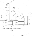
- Fig. 1 shows a converter 1 which is buried in the ground.
- the ground surface is denoted by reference numeral 5.
- the converter 1 is located in a cavity 2 having walls 4 and a lid 7.
- the lid 7 extends on the same height level as the surface 5 of the ground.
- the surface 5 of the ground steps down to a lower height level, the upper surface of which is formed by the material of a road 8 (i.e. a path of travel) for trucks, automobiles and/or busses.
- a road 8 i.e. a path of travel
- the area which is denoted by 8 may be a parking space for a land vehicle or the track of a rail vehicle.
- Below the surface of the road 8, parking space or track there is an arrangement 10 of electric conductors which produce an alternating electromagnetic field during operation, in order to transfer energy to a vehicle by induction.
- the converter 1 produces the alternating current which is transferred to the arrangement 10 via electric connection lines 19a, 19b. Further electric connections of the converter 1, such as connections to a feed line, are not shown in Fig. 1 .
- additional electronic and/or electric devices may also be located within the cavity 2, in particular within the same housing which contains the converter 1.
- Fig. 1 schematically shows that a cooling device 3 is combined with the converter 1.
- a forward section 14a of a conduct extends from the cooling device 3 to a pole 13 and further extends inside the pole 13 to the top region of the pole 13.
- the forward section 14a is connected to a return section 14b of the conduct which extends through the pole 13 and the ground back to the cooling device 3.
- the forward section 14a, the connecting section 14c and the return section 14b form a conduct loop through which a heat transport medium, such as a liquid transport medium, can flow during operation.
- the cooling device 3 comprises a pump or the like for forcing the heat transport medium through the conduct loop.
- the pole 13 is founded using a foundation 12 in the ground for stability reasons.
- the outer wall of the pole 13 comprises at least one air inlet opening 17a and at least one air outlet opening 17b.
- At least one air channel 16 extends from the air inlet opening 17a to the air outlet opening 17b.
- ambiance air can enter the air channel via the air inlet opening 17a, can flow through the at least one air channel 16 and can leave the interior of the pole 13 via the air outlet opening 17b. Therefore, heat which is transferred from the cooling device 3 away from the converter 1 via the heat transport medium inside the conduct loop can be transferred inside the pole 13 to the air which flows through the at least one air channel 16. Cooling of the converter is improved thereby.
- Fig. 2 shows a specific embodiment of a profile of a pole 23 which can be used for the pole 13 of Fig. 1 , for example, or for any other pole or supporting structure in connection with the present invention.
- the cross section shown in Fig. 2 is, for example, a horizontal cross section, if the pole 23 extends in vertical direction upwards from ground.
- the pole 23 comprises four parallel conduct sections 21 a, 21 b, 21c, 21d which have circular shapes.
- two of the conduct sections 21 may be forward sections and two may be return sections.
- the resulting conduct loops may be parallel loops, which means that the same particles of the heat transport medium are not flowing through both conduct loops, before they return to the cooling device at the converter.
- the conduct sections 21 are formed in a central region of the pole's cross section.
- the center of the central region comprises a cavity 25 in order to reduce weight and in order to safe material (for example metal, such as aluminum).
- the center cavity 25 may also be used as an air channel through which ambient air may pass.
- cooling bodies 24 extend from the central region to an outer wall 28 of the pole 23.
- These cooling bodies 24 extend approximately in radial direction from the central region of the cross section shown in Fig. 2 .
- the outer wall 28 extends on a circle around the central region. More generally speaking, the outer wall extends around the central region. Therefore, the outer wall 28 and in each case two neighboring cooling bodies 24 delimit one air channel 22 having an approximately triangular shape in the cross section.
- the number of the conduct sections in the central region, the number of the cooling bodies which extend in radial direction and, therefore, the number of the air channels delimited by each pair of neighboring cooling bodies may vary.
- a space 26 is provided which may be used for placing electric cables inside the space 26.
- a removable cover 27 covers the space 26.
- the cover 27 follows the circular outline of the pole 23. In other embodiments, the space 26 and the cover 27 can be omitted.
- the cross section shown in Fig. 2 is preferably constant, at least over a significant part of the pole's extension in a direction perpendicular to the image plane of Fig. 2 .
- a significant part of the lengthwise extension is, for example, 50% and preferably more than 70% of the total lengthwise extension of the pole.
- air inlet openings and air outlet openings similar to the openings 17 shown in Fig. 1 are formed in the wall 28 of the pole 23 at desired location. These inlet and outlet openings are not shown in Fig. 2 .
Landscapes
- Engineering & Computer Science (AREA)
- Microelectronics & Electronic Packaging (AREA)
- Power Engineering (AREA)
- Physics & Mathematics (AREA)
- Thermal Sciences (AREA)
- Transportation (AREA)
- Mechanical Engineering (AREA)
- Electric Propulsion And Braking For Vehicles (AREA)
- Cooling Or The Like Of Electrical Apparatus (AREA)
- Inverter Devices (AREA)
- Rectifiers (AREA)
Claims (6)
- Anordnung zum Betreiben eines Stromrichters (1), wobei- der Stromrichter (1) sich an einem Fahrweg (8) von Landfahrzeugen oder an einem Parkplatz eines Landfahrzeugs befindet, wobei der Stromrichter (1) zum Unterstützen des Betriebs von wenigstens einem Fahrzeug ausgeführt ist,- der Stromrichter (1) mit einer Kühlvorrichtung (3) kombiniert ist, die zum Kühlen des Stromrichters (1) während des Betriebs ausgeführt ist,- die Kühlvorrichtung (3) zur Verwendung eines Wärmetransportmediums ausgelegt ist, um Wärme vom Stromrichter (1) weg zu transportieren,- die Anordnung wenigstens einen Mast (13) und/oder wenigstens eine Trägerstruktur aufweist, der bzw. die sich ebenfalls an dem Fahrweg (8) oder an dem Parkplatz befindet,dadurch gekennzeichnet, dass- der Mast (13) und/oder die Trägerstruktur sich vom Boden nach oben erstreckt,- die Anordnung eine Leitungsschleife (14) zum Leiten des Wärmetransportmediums aufweist,- das Wärmetransportmedium während des Betriebs der Leitungsschleife (14) von der Kühlvorrichtung (3) durch einen Vorlaufabschnitt der Leitungsschleife (14) und einen Rücklaufabschnitt der Leitungsschleife (14) zur Kühlvorrichtung (3) zurück zirkuliert und- der Vorlaufabschnitt und der Rücklaufabschnitt der Leitungsschleife (14) sich von der Kühlvorrichtung (3) zu dem Mast (13) und/oder der Trägerstruktur erstrecken und sich auch im Inneren des Masten (13) und/oder im Inneren der Trägerstruktur erstrecken, so dass ein Wärmeübertrager in den Mast (13) und/oder die Trägerstruktur integriert ist, wobei dieser Wärmeübertrager - während des Betriebs der Leitungsschleife (14) - Wärme vom Wärmetransportmedium im Inneren des Masten (13) und/oder im Inneren der Trägerstruktur an die Umgebung überträgt.
- Anordnung nach Anspruch 1, wobei der Vorlaufabschnitt und der Rücklaufabschnitt der Leitungsschleife (14) sich durch den Untergrund und/oder an der Oberfläche (5) des Untergrunds von der Kühlvorrichtung (3) zu dem Mast (13) und/oder der Trägerstruktur erstrecken.
- Anordnung nach Anspruch 1 oder 2, wobei der in den Mast (13) und/oder die Trägerstruktur integrierte Wärmeübertrager Kühlkörper (24) aufweist, die sich von der Oberfläche der Leitungsschleife (14) im Inneren des Masten (13) und/oder im Inneren der Trägerstruktur wegerstrecken, um Wärme durch das Material der Kühlkörper (24) von der Leitungsschleife (14) wegzuleiten, wobei der Mast (13) und/oder die Trägerstruktur auch wenigstens einen Luftkanal (22) aufweist, der sich von einer Lufteinlassöffnung (17a) des Masten (13) und/oder der Trägerstruktur nach oben zu einer Luftauslassöffnung (17b) des Masten (13) und/oder der Trägerstruktur erstreckt, und wobei wenigstens einer der Kühlkörper (24) wenigstens Teil einer Wand des wenigstens einen Luftkanals (22) bildet.
- Verfahren zum Betreiben eines Stromrichters (1), wobei- der Stromrichter (1) an einem Fahrweg (8) von Landfahrzeugen oder an einem Parkplatz eines Landfahrzeugs betrieben wird, wobei der Stromrichter (1) zum Unterstützen des Betriebs wenigstens eines Fahrzeugs ausgeführt ist,- eine Kühlvorrichtung (3) zum Kühlen des Stromrichters (1) während des Betriebs verwendet wird,- die Kühlvorrichtung (3) ein Wärmetransportmedium für den Wärmetransport vom Stromrichter (1) weg verwendet,- wenigstens ein Mast (13) und/oder wenigstens eine Trägerstruktur, der bzw. die sich ebenfalls an dem Fahrweg (8) oder an dem Parkplatz befindet, zur Übertragung von während des Betriebs des Stromrichters (1) erzeugter Wärme an die Umgebung verwendet wird,dadurch gekennzeichnet, dass- eine Leitungsschleife (14) zum Leiten des Wärmetransportmediums von der Kühlvorrichtung (3) zu dem Mast (13) und/oder der Trägerstruktur verwendet wird,- das Wärmetransportmedium von der Kühlvorrichtung (3) durch einen Vorlaufabschnitt der Leitungsschleife (14) und einen Rücklaufabschnitt der Leitungsschleife (14) zur Kühlvorrichtung (3) zurück zirkuliert und- das Wärmetransportmedium durch einen Abschnitt der Leitungsschleife (14) im Inneren des Masten (13) und/oder im Inneren der Trägerstruktur geleitet wird, so dass Wärme vom Wärmetransportmedium im Inneren des Masten (13) und/oder der Trägerstruktur über einen in den Mast (13) und/oder die Trägerstruktur integrierten Wärmeübertrager an die Umgebung übertragen wird.
- Verfahren nach Anspruch 4, wobei das Wärmetransportmedium im Inneren der Leitungsschleife (14) durch den Untergrund und/oder an der Oberfläche (5) des Untergrunds von der Kühlvorrichtung (3) zu dem Mast (13) und/oder der Trägerstruktur geleitet wird.
- Verfahren nach Anspruch 4 oder 5, wobei Wärme von der Leitungsschleife (14) im Inneren des Masten (13) und/oder im Inneren der Trägerstruktur von der Oberfläche der Leitungsschleife (14) im Inneren des Masten (13) und/oder im Inneren der Trägerstruktur durch Material von wenigstens einem Kühlkörper (24) des Wärmeübertragers weggeleitet wird, wobei die Wärme von dem wenigstens einen Kühlkörper (24), der wenigstens Teil einer Wand wenigstens eines Luftkanals (22) im Inneren des Masten (13) und/oder im Inneren der Trägerstruktur im Inneren des Masten und/oder im Inneren der Trägerstruktur bildet, an Umgebungsluft im Inneren des Luftkanals (22) übertragen wird, während die Umgebungsluft von einer Lufteinlassöffnung (17a) des Masten (13) und/oder der Trägerstruktur nach oben zu einer Luftauslassöffnung (17b) des Masten (13) und/oder der Trägerstruktur strömt.
Applications Claiming Priority (2)
| Application Number | Priority Date | Filing Date | Title |
|---|---|---|---|
| GB1205439.1A GB2500640A (en) | 2012-03-27 | 2012-03-27 | Cooling arrangement for converter for transferring electric energy to a land vehicle |
| PCT/EP2013/056076 WO2013144014A1 (en) | 2012-03-27 | 2013-03-22 | Operating a current converter at a path of travel of land vehicles or at a parking space of a land vehicle |
Publications (2)
| Publication Number | Publication Date |
|---|---|
| EP2830908A1 EP2830908A1 (de) | 2015-02-04 |
| EP2830908B1 true EP2830908B1 (de) | 2017-03-08 |
Family
ID=46087250
Family Applications (1)
| Application Number | Title | Priority Date | Filing Date |
|---|---|---|---|
| EP13712222.2A Not-in-force EP2830908B1 (de) | 2012-03-27 | 2013-03-22 | Betrieb eines stromrichters an einem fahrweg von landfahrzeugen oder an einer parklücke eines landfahrzeugs |
Country Status (11)
| Country | Link |
|---|---|
| US (1) | US9351433B2 (de) |
| EP (1) | EP2830908B1 (de) |
| KR (1) | KR20140137397A (de) |
| CN (1) | CN104136265B (de) |
| AU (1) | AU2013242014A1 (de) |
| CA (1) | CA2861596C (de) |
| ES (1) | ES2625633T3 (de) |
| GB (1) | GB2500640A (de) |
| IN (1) | IN2014DN06649A (de) |
| NZ (1) | NZ627797A (de) |
| WO (1) | WO2013144014A1 (de) |
Families Citing this family (4)
| Publication number | Priority date | Publication date | Assignee | Title |
|---|---|---|---|---|
| CN107139739B (zh) * | 2016-08-26 | 2019-10-25 | 宁波三星医疗电气股份有限公司 | 一种利用液冷散热的充电桩及散热控制方法 |
| KR101999127B1 (ko) * | 2017-04-05 | 2019-07-11 | 한국전력공사 | 컨버터 분리형 전기차 충전 시스템 |
| DE102017209383A1 (de) | 2017-06-02 | 2018-12-06 | Audi Ag | System zum Versorgen eines Fahrzeugs mit elektrischer Energie |
| CN108749632B (zh) * | 2018-07-06 | 2021-09-14 | 宁格朗电气股份有限公司 | 一种利用太阳能发电的耐高温充电桩 |
Family Cites Families (17)
| Publication number | Priority date | Publication date | Assignee | Title |
|---|---|---|---|---|
| DE4114576A1 (de) | 1991-05-04 | 1991-10-24 | Norbert Fiedler | Verfahren zur selbstkuehlung von transformatoren und batterieladegeraeten oder anderen waermeerzeugenden stromversorgungsgeraeten in geschlossenen gehaeusen |
| EP0552737A1 (de) * | 1992-01-22 | 1993-07-28 | Hughes Aircraft Company | Wetterfester längsseitiger Lader |
| EP0982832A3 (de) * | 1996-08-07 | 2000-08-09 | Sumitomo Wiring Systems, Ltd. | Ladesystem für elektrisches Fahrzeug |
| JPH10294579A (ja) * | 1997-04-18 | 1998-11-04 | Sansha Electric Mfg Co Ltd | 電源装置 |
| FR2779392B1 (fr) * | 1998-06-04 | 2004-01-23 | Cegelec Sa | Systeme d'alimentation par le sol pour vehicule electrique et vehicule equipe pour utiliser un tel systeme |
| JP2001176739A (ja) * | 1999-12-14 | 2001-06-29 | Toyota Autom Loom Works Ltd | 車両用電磁誘導型非接触充電装置 |
| US20050161861A1 (en) * | 2003-09-26 | 2005-07-28 | Brunswick Corporation | Apparatus and method for making preforms in mold |
| JP4715708B2 (ja) * | 2006-10-03 | 2011-07-06 | トヨタ自動車株式会社 | 電動車両および車両充電システム |
| GB2463692A (en) | 2008-09-19 | 2010-03-24 | Bombardier Transp Gmbh | An arrangement for providing a vehicle with electric energy |
| BR112012001041A2 (pt) | 2009-07-15 | 2016-03-15 | Conductix Wampfler Ag | sistema para o carregamento indutivo de veículos com auxiliar de posicionamento eletrônico |
| EP2483921A2 (de) * | 2009-09-28 | 2012-08-08 | ABB Research Ltd. | Kühlmodul zur kühlung von elektronischen komponenten |
| GB2477080A (en) | 2009-12-21 | 2011-07-27 | Bombardier Transp Gmbh | Modular track for vehicle using inductive energy transfer |
| GB2476313A (en) | 2009-12-21 | 2011-06-22 | Bombardier Transp Gmbh | Cooling of electronic devices located in a ground cavity |
| CN201608217U (zh) * | 2009-12-31 | 2010-10-13 | 深圳日海通讯技术股份有限公司 | 一种地埋式电池柜 |
| WO2011106506A2 (en) * | 2010-02-25 | 2011-09-01 | Evatran Llc | Method and apparatus for inductively transferring ac power between a charging unit and a vehicle |
| US8174235B2 (en) * | 2011-07-25 | 2012-05-08 | Lightening Energy | System and method for recharging electric vehicle batteries |
| US8350526B2 (en) * | 2011-07-25 | 2013-01-08 | Lightening Energy | Station for rapidly charging an electric vehicle battery |
-
2012
- 2012-03-27 GB GB1205439.1A patent/GB2500640A/en not_active Withdrawn
-
2013
- 2013-03-22 US US14/388,524 patent/US9351433B2/en not_active Expired - Fee Related
- 2013-03-22 ES ES13712222.2T patent/ES2625633T3/es active Active
- 2013-03-22 AU AU2013242014A patent/AU2013242014A1/en not_active Abandoned
- 2013-03-22 WO PCT/EP2013/056076 patent/WO2013144014A1/en not_active Ceased
- 2013-03-22 CA CA2861596A patent/CA2861596C/en not_active Expired - Fee Related
- 2013-03-22 IN IN6649DEN2014 patent/IN2014DN06649A/en unknown
- 2013-03-22 EP EP13712222.2A patent/EP2830908B1/de not_active Not-in-force
- 2013-03-22 NZ NZ627797A patent/NZ627797A/en not_active IP Right Cessation
- 2013-03-22 KR KR20147027031A patent/KR20140137397A/ko not_active Withdrawn
- 2013-03-22 CN CN201380011657.1A patent/CN104136265B/zh not_active Expired - Fee Related
Also Published As
| Publication number | Publication date |
|---|---|
| KR20140137397A (ko) | 2014-12-02 |
| AU2013242014A1 (en) | 2014-08-14 |
| IN2014DN06649A (de) | 2015-05-22 |
| CN104136265A (zh) | 2014-11-05 |
| ES2625633T3 (es) | 2017-07-20 |
| WO2013144014A1 (en) | 2013-10-03 |
| EP2830908A1 (de) | 2015-02-04 |
| GB2500640A (en) | 2013-10-02 |
| US20150116936A1 (en) | 2015-04-30 |
| CA2861596A1 (en) | 2013-10-03 |
| GB201205439D0 (en) | 2012-05-09 |
| CA2861596C (en) | 2019-04-16 |
| US9351433B2 (en) | 2016-05-24 |
| CN104136265B (zh) | 2017-04-19 |
| HK1208012A1 (en) | 2016-02-19 |
| NZ627797A (en) | 2016-04-29 |
Similar Documents
| Publication | Publication Date | Title |
|---|---|---|
| CN101682268B (zh) | 功率转换装置 | |
| EP2830908B1 (de) | Betrieb eines stromrichters an einem fahrweg von landfahrzeugen oder an einer parklücke eines landfahrzeugs | |
| US5491370A (en) | Integrated AC machine | |
| US10064316B2 (en) | Vehicular power conversion device | |
| EP2516200B1 (de) | System zur energieübertragung auf ein fahrzeug und betriebsverfahren für das system | |
| JP5148238B2 (ja) | 高速鉄道車両用電力変換装置 | |
| CN104283405B (zh) | 电力转换装置及搭载了该电子转换装置的铁道车辆 | |
| CN103303121A (zh) | 用于混合动力车辆的电气部件固定结构 | |
| US20220037963A1 (en) | Insulating device with cooling medium line | |
| US11482885B2 (en) | Stationary part for an inductive power transfer pad | |
| CN109713178A (zh) | 一种动力电池水冷模组 | |
| JP5571039B2 (ja) | 誘導加熱式融雪システム | |
| CN108349703A (zh) | 具有冷却装置的电梯线性推进系统 | |
| HK1208012B (en) | Operating a current converter at a path of travel of land vehicles or at a parking space of a land vehicle | |
| JP7408017B2 (ja) | 電子機器 | |
| ES2350532T3 (es) | Unidad de montaje para un vehículo motriz sobre rieles. | |
| JP5769980B2 (ja) | 鉄道車両の遮熱カバー | |
| CN205022582U (zh) | 一种列车电机冷却系统 | |
| CN221541300U (zh) | 地面设备及无线充电系统 | |
| CN221930482U (zh) | 电子设备 | |
| CN215578719U (zh) | 一种车用电池冷却装置 | |
| KR20260046295A (ko) | 비히클용 모듈식 파워 컨버터 시스템 | |
| CN201426082Y (zh) | 强迫风冷大推力扁平型三相直线异步电动机 | |
| CN101572475B (zh) | 强迫风冷大推力扁平型三相直线异步电动机 | |
| JPH0441745Y2 (de) |
Legal Events
| Date | Code | Title | Description |
|---|---|---|---|
| PUAI | Public reference made under article 153(3) epc to a published international application that has entered the european phase |
Free format text: ORIGINAL CODE: 0009012 |
|
| 17P | Request for examination filed |
Effective date: 20140924 |
|
| AK | Designated contracting states |
Kind code of ref document: A1 Designated state(s): AL AT BE BG CH CY CZ DE DK EE ES FI FR GB GR HR HU IE IS IT LI LT LU LV MC MK MT NL NO PL PT RO RS SE SI SK SM TR |
|
| AX | Request for extension of the european patent |
Extension state: BA ME |
|
| DAX | Request for extension of the european patent (deleted) | ||
| REG | Reference to a national code |
Ref country code: HK Ref legal event code: DE Ref document number: 1208012 Country of ref document: HK |
|
| RAP1 | Party data changed (applicant data changed or rights of an application transferred) |
Owner name: BOMBARDIER PRIMOVE GMBH |
|
| RAP1 | Party data changed (applicant data changed or rights of an application transferred) |
Owner name: BOMBARDIER PRIMOVE GMBH |
|
| GRAP | Despatch of communication of intention to grant a patent |
Free format text: ORIGINAL CODE: EPIDOSNIGR1 |
|
| INTG | Intention to grant announced |
Effective date: 20160920 |
|
| GRAS | Grant fee paid |
Free format text: ORIGINAL CODE: EPIDOSNIGR3 |
|
| GRAA | (expected) grant |
Free format text: ORIGINAL CODE: 0009210 |
|
| AK | Designated contracting states |
Kind code of ref document: B1 Designated state(s): AL AT BE BG CH CY CZ DE DK EE ES FI FR GB GR HR HU IE IS IT LI LT LU LV MC MK MT NL NO PL PT RO RS SE SI SK SM TR |
|
| REG | Reference to a national code |
Ref country code: GB Ref legal event code: FG4D |
|
| REG | Reference to a national code |
Ref country code: CH Ref legal event code: EP Ref country code: AT Ref legal event code: REF Ref document number: 873211 Country of ref document: AT Kind code of ref document: T Effective date: 20170315 |
|
| REG | Reference to a national code |
Ref country code: FR Ref legal event code: PLFP Year of fee payment: 5 |
|
| REG | Reference to a national code |
Ref country code: IE Ref legal event code: FG4D |
|
| REG | Reference to a national code |
Ref country code: DE Ref legal event code: R096 Ref document number: 602013018257 Country of ref document: DE |
|
| REG | Reference to a national code |
Ref country code: LT Ref legal event code: MG4D |
|
| REG | Reference to a national code |
Ref country code: NL Ref legal event code: MP Effective date: 20170308 |
|
| REG | Reference to a national code |
Ref country code: ES Ref legal event code: FG2A Ref document number: 2625633 Country of ref document: ES Kind code of ref document: T3 Effective date: 20170720 |
|
| PG25 | Lapsed in a contracting state [announced via postgrant information from national office to epo] |
Ref country code: NO Free format text: LAPSE BECAUSE OF FAILURE TO SUBMIT A TRANSLATION OF THE DESCRIPTION OR TO PAY THE FEE WITHIN THE PRESCRIBED TIME-LIMIT Effective date: 20170608 Ref country code: GR Free format text: LAPSE BECAUSE OF FAILURE TO SUBMIT A TRANSLATION OF THE DESCRIPTION OR TO PAY THE FEE WITHIN THE PRESCRIBED TIME-LIMIT Effective date: 20170609 Ref country code: LT Free format text: LAPSE BECAUSE OF FAILURE TO SUBMIT A TRANSLATION OF THE DESCRIPTION OR TO PAY THE FEE WITHIN THE PRESCRIBED TIME-LIMIT Effective date: 20170308 Ref country code: FI Free format text: LAPSE BECAUSE OF FAILURE TO SUBMIT A TRANSLATION OF THE DESCRIPTION OR TO PAY THE FEE WITHIN THE PRESCRIBED TIME-LIMIT Effective date: 20170308 Ref country code: HR Free format text: LAPSE BECAUSE OF FAILURE TO SUBMIT A TRANSLATION OF THE DESCRIPTION OR TO PAY THE FEE WITHIN THE PRESCRIBED TIME-LIMIT Effective date: 20170308 |
|
| REG | Reference to a national code |
Ref country code: AT Ref legal event code: MK05 Ref document number: 873211 Country of ref document: AT Kind code of ref document: T Effective date: 20170308 |
|
| PG25 | Lapsed in a contracting state [announced via postgrant information from national office to epo] |
Ref country code: LV Free format text: LAPSE BECAUSE OF FAILURE TO SUBMIT A TRANSLATION OF THE DESCRIPTION OR TO PAY THE FEE WITHIN THE PRESCRIBED TIME-LIMIT Effective date: 20170308 Ref country code: RS Free format text: LAPSE BECAUSE OF FAILURE TO SUBMIT A TRANSLATION OF THE DESCRIPTION OR TO PAY THE FEE WITHIN THE PRESCRIBED TIME-LIMIT Effective date: 20170308 Ref country code: SE Free format text: LAPSE BECAUSE OF FAILURE TO SUBMIT A TRANSLATION OF THE DESCRIPTION OR TO PAY THE FEE WITHIN THE PRESCRIBED TIME-LIMIT Effective date: 20170308 Ref country code: BG Free format text: LAPSE BECAUSE OF FAILURE TO SUBMIT A TRANSLATION OF THE DESCRIPTION OR TO PAY THE FEE WITHIN THE PRESCRIBED TIME-LIMIT Effective date: 20170608 |
|
| PG25 | Lapsed in a contracting state [announced via postgrant information from national office to epo] |
Ref country code: NL Free format text: LAPSE BECAUSE OF FAILURE TO SUBMIT A TRANSLATION OF THE DESCRIPTION OR TO PAY THE FEE WITHIN THE PRESCRIBED TIME-LIMIT Effective date: 20170308 |
|
| PG25 | Lapsed in a contracting state [announced via postgrant information from national office to epo] |
Ref country code: RO Free format text: LAPSE BECAUSE OF FAILURE TO SUBMIT A TRANSLATION OF THE DESCRIPTION OR TO PAY THE FEE WITHIN THE PRESCRIBED TIME-LIMIT Effective date: 20170308 Ref country code: EE Free format text: LAPSE BECAUSE OF FAILURE TO SUBMIT A TRANSLATION OF THE DESCRIPTION OR TO PAY THE FEE WITHIN THE PRESCRIBED TIME-LIMIT Effective date: 20170308 Ref country code: SK Free format text: LAPSE BECAUSE OF FAILURE TO SUBMIT A TRANSLATION OF THE DESCRIPTION OR TO PAY THE FEE WITHIN THE PRESCRIBED TIME-LIMIT Effective date: 20170308 Ref country code: AT Free format text: LAPSE BECAUSE OF FAILURE TO SUBMIT A TRANSLATION OF THE DESCRIPTION OR TO PAY THE FEE WITHIN THE PRESCRIBED TIME-LIMIT Effective date: 20170308 Ref country code: CZ Free format text: LAPSE BECAUSE OF FAILURE TO SUBMIT A TRANSLATION OF THE DESCRIPTION OR TO PAY THE FEE WITHIN THE PRESCRIBED TIME-LIMIT Effective date: 20170308 |
|
| REG | Reference to a national code |
Ref country code: CH Ref legal event code: PL |
|
| PG25 | Lapsed in a contracting state [announced via postgrant information from national office to epo] |
Ref country code: SM Free format text: LAPSE BECAUSE OF FAILURE TO SUBMIT A TRANSLATION OF THE DESCRIPTION OR TO PAY THE FEE WITHIN THE PRESCRIBED TIME-LIMIT Effective date: 20170308 Ref country code: IS Free format text: LAPSE BECAUSE OF FAILURE TO SUBMIT A TRANSLATION OF THE DESCRIPTION OR TO PAY THE FEE WITHIN THE PRESCRIBED TIME-LIMIT Effective date: 20170708 Ref country code: PL Free format text: LAPSE BECAUSE OF FAILURE TO SUBMIT A TRANSLATION OF THE DESCRIPTION OR TO PAY THE FEE WITHIN THE PRESCRIBED TIME-LIMIT Effective date: 20170308 Ref country code: PT Free format text: LAPSE BECAUSE OF FAILURE TO SUBMIT A TRANSLATION OF THE DESCRIPTION OR TO PAY THE FEE WITHIN THE PRESCRIBED TIME-LIMIT Effective date: 20170710 |
|
| REG | Reference to a national code |
Ref country code: DE Ref legal event code: R097 Ref document number: 602013018257 Country of ref document: DE |
|
| REG | Reference to a national code |
Ref country code: IE Ref legal event code: MM4A |
|
| PLBE | No opposition filed within time limit |
Free format text: ORIGINAL CODE: 0009261 |
|
| STAA | Information on the status of an ep patent application or granted ep patent |
Free format text: STATUS: NO OPPOSITION FILED WITHIN TIME LIMIT |
|
| PG25 | Lapsed in a contracting state [announced via postgrant information from national office to epo] |
Ref country code: LU Free format text: LAPSE BECAUSE OF NON-PAYMENT OF DUE FEES Effective date: 20170322 Ref country code: DK Free format text: LAPSE BECAUSE OF FAILURE TO SUBMIT A TRANSLATION OF THE DESCRIPTION OR TO PAY THE FEE WITHIN THE PRESCRIBED TIME-LIMIT Effective date: 20170308 Ref country code: MC Free format text: LAPSE BECAUSE OF FAILURE TO SUBMIT A TRANSLATION OF THE DESCRIPTION OR TO PAY THE FEE WITHIN THE PRESCRIBED TIME-LIMIT Effective date: 20170308 |
|
| 26N | No opposition filed |
Effective date: 20171211 |
|
| PG25 | Lapsed in a contracting state [announced via postgrant information from national office to epo] |
Ref country code: IE Free format text: LAPSE BECAUSE OF NON-PAYMENT OF DUE FEES Effective date: 20170322 Ref country code: LI Free format text: LAPSE BECAUSE OF NON-PAYMENT OF DUE FEES Effective date: 20170331 Ref country code: CH Free format text: LAPSE BECAUSE OF NON-PAYMENT OF DUE FEES Effective date: 20170331 Ref country code: SI Free format text: LAPSE BECAUSE OF FAILURE TO SUBMIT A TRANSLATION OF THE DESCRIPTION OR TO PAY THE FEE WITHIN THE PRESCRIBED TIME-LIMIT Effective date: 20170308 |
|
| REG | Reference to a national code |
Ref country code: BE Ref legal event code: MM Effective date: 20170331 |
|
| REG | Reference to a national code |
Ref country code: FR Ref legal event code: PLFP Year of fee payment: 6 |
|
| REG | Reference to a national code |
Ref country code: HK Ref legal event code: GR Ref document number: 1208012 Country of ref document: HK |
|
| PGFP | Annual fee paid to national office [announced via postgrant information from national office to epo] |
Ref country code: GB Payment date: 20180321 Year of fee payment: 6 |
|
| PG25 | Lapsed in a contracting state [announced via postgrant information from national office to epo] |
Ref country code: BE Free format text: LAPSE BECAUSE OF NON-PAYMENT OF DUE FEES Effective date: 20170331 |
|
| PGFP | Annual fee paid to national office [announced via postgrant information from national office to epo] |
Ref country code: ES Payment date: 20180430 Year of fee payment: 6 |
|
| PG25 | Lapsed in a contracting state [announced via postgrant information from national office to epo] |
Ref country code: MT Free format text: LAPSE BECAUSE OF NON-PAYMENT OF DUE FEES Effective date: 20170322 |
|
| PG25 | Lapsed in a contracting state [announced via postgrant information from national office to epo] |
Ref country code: HU Free format text: LAPSE BECAUSE OF FAILURE TO SUBMIT A TRANSLATION OF THE DESCRIPTION OR TO PAY THE FEE WITHIN THE PRESCRIBED TIME-LIMIT; INVALID AB INITIO Effective date: 20130322 |
|
| PG25 | Lapsed in a contracting state [announced via postgrant information from national office to epo] |
Ref country code: CY Free format text: LAPSE BECAUSE OF FAILURE TO SUBMIT A TRANSLATION OF THE DESCRIPTION OR TO PAY THE FEE WITHIN THE PRESCRIBED TIME-LIMIT Effective date: 20170308 |
|
| GBPC | Gb: european patent ceased through non-payment of renewal fee |
Effective date: 20190322 |
|
| PG25 | Lapsed in a contracting state [announced via postgrant information from national office to epo] |
Ref country code: MK Free format text: LAPSE BECAUSE OF FAILURE TO SUBMIT A TRANSLATION OF THE DESCRIPTION OR TO PAY THE FEE WITHIN THE PRESCRIBED TIME-LIMIT Effective date: 20170308 |
|
| PG25 | Lapsed in a contracting state [announced via postgrant information from national office to epo] |
Ref country code: GB Free format text: LAPSE BECAUSE OF NON-PAYMENT OF DUE FEES Effective date: 20190322 |
|
| PG25 | Lapsed in a contracting state [announced via postgrant information from national office to epo] |
Ref country code: TR Free format text: LAPSE BECAUSE OF FAILURE TO SUBMIT A TRANSLATION OF THE DESCRIPTION OR TO PAY THE FEE WITHIN THE PRESCRIBED TIME-LIMIT Effective date: 20170308 |
|
| PGFP | Annual fee paid to national office [announced via postgrant information from national office to epo] |
Ref country code: DE Payment date: 20200320 Year of fee payment: 8 Ref country code: IT Payment date: 20200331 Year of fee payment: 8 |
|
| PGFP | Annual fee paid to national office [announced via postgrant information from national office to epo] |
Ref country code: FR Payment date: 20200320 Year of fee payment: 8 |
|
| REG | Reference to a national code |
Ref country code: ES Ref legal event code: FD2A Effective date: 20200728 |
|
| PG25 | Lapsed in a contracting state [announced via postgrant information from national office to epo] |
Ref country code: AL Free format text: LAPSE BECAUSE OF FAILURE TO SUBMIT A TRANSLATION OF THE DESCRIPTION OR TO PAY THE FEE WITHIN THE PRESCRIBED TIME-LIMIT Effective date: 20170308 |
|
| PG25 | Lapsed in a contracting state [announced via postgrant information from national office to epo] |
Ref country code: ES Free format text: LAPSE BECAUSE OF NON-PAYMENT OF DUE FEES Effective date: 20190323 |
|
| REG | Reference to a national code |
Ref country code: DE Ref legal event code: R119 Ref document number: 602013018257 Country of ref document: DE |
|
| PG25 | Lapsed in a contracting state [announced via postgrant information from national office to epo] |
Ref country code: FR Free format text: LAPSE BECAUSE OF NON-PAYMENT OF DUE FEES Effective date: 20210331 Ref country code: DE Free format text: LAPSE BECAUSE OF NON-PAYMENT OF DUE FEES Effective date: 20211001 |
|
| PG25 | Lapsed in a contracting state [announced via postgrant information from national office to epo] |
Ref country code: IT Free format text: LAPSE BECAUSE OF NON-PAYMENT OF DUE FEES Effective date: 20210322 |