EP2831400B1 - Procédé pour faire fonctionner un moteur à combustion interne - Google Patents
Procédé pour faire fonctionner un moteur à combustion interne Download PDFInfo
- Publication number
- EP2831400B1 EP2831400B1 EP13718296.0A EP13718296A EP2831400B1 EP 2831400 B1 EP2831400 B1 EP 2831400B1 EP 13718296 A EP13718296 A EP 13718296A EP 2831400 B1 EP2831400 B1 EP 2831400B1
- Authority
- EP
- European Patent Office
- Prior art keywords
- internal combustion
- operating mode
- combustion engine
- valve
- ignition
- Prior art date
- Legal status (The legal status is an assumption and is not a legal conclusion. Google has not performed a legal analysis and makes no representation as to the accuracy of the status listed.)
- Active
Links
Images
Classifications
-
- F—MECHANICAL ENGINEERING; LIGHTING; HEATING; WEAPONS; BLASTING
- F02—COMBUSTION ENGINES; HOT-GAS OR COMBUSTION-PRODUCT ENGINE PLANTS
- F02D—CONTROLLING COMBUSTION ENGINES
- F02D13/00—Controlling the engine output power by varying inlet or exhaust valve operating characteristics, e.g. timing
- F02D13/02—Controlling the engine output power by varying inlet or exhaust valve operating characteristics, e.g. timing during engine operation
- F02D13/0223—Variable control of the intake valves only
- F02D13/0226—Variable control of the intake valves only changing valve lift or valve lift and timing
-
- F—MECHANICAL ENGINEERING; LIGHTING; HEATING; WEAPONS; BLASTING
- F02—COMBUSTION ENGINES; HOT-GAS OR COMBUSTION-PRODUCT ENGINE PLANTS
- F02D—CONTROLLING COMBUSTION ENGINES
- F02D41/00—Electrical control of supply of combustible mixture or its constituents
- F02D41/30—Controlling fuel injection
- F02D41/3011—Controlling fuel injection according to or using specific or several modes of combustion
- F02D41/3017—Controlling fuel injection according to or using specific or several modes of combustion characterised by the mode(s) being used
-
- F—MECHANICAL ENGINEERING; LIGHTING; HEATING; WEAPONS; BLASTING
- F02—COMBUSTION ENGINES; HOT-GAS OR COMBUSTION-PRODUCT ENGINE PLANTS
- F02B—INTERNAL-COMBUSTION PISTON ENGINES; COMBUSTION ENGINES IN GENERAL
- F02B17/00—Engines characterised by means for effecting stratification of charge in cylinders
- F02B17/005—Engines characterised by means for effecting stratification of charge in cylinders having direct injection in the combustion chamber
-
- F—MECHANICAL ENGINEERING; LIGHTING; HEATING; WEAPONS; BLASTING
- F02—COMBUSTION ENGINES; HOT-GAS OR COMBUSTION-PRODUCT ENGINE PLANTS
- F02D—CONTROLLING COMBUSTION ENGINES
- F02D13/00—Controlling the engine output power by varying inlet or exhaust valve operating characteristics, e.g. timing
- F02D13/02—Controlling the engine output power by varying inlet or exhaust valve operating characteristics, e.g. timing during engine operation
- F02D13/0203—Variable control of intake and exhaust valves
- F02D13/0207—Variable control of intake and exhaust valves changing valve lift or valve lift and timing
-
- F—MECHANICAL ENGINEERING; LIGHTING; HEATING; WEAPONS; BLASTING
- F02—COMBUSTION ENGINES; HOT-GAS OR COMBUSTION-PRODUCT ENGINE PLANTS
- F02D—CONTROLLING COMBUSTION ENGINES
- F02D41/00—Electrical control of supply of combustible mixture or its constituents
- F02D41/0002—Controlling intake air
-
- F—MECHANICAL ENGINEERING; LIGHTING; HEATING; WEAPONS; BLASTING
- F02—COMBUSTION ENGINES; HOT-GAS OR COMBUSTION-PRODUCT ENGINE PLANTS
- F02D—CONTROLLING COMBUSTION ENGINES
- F02D41/00—Electrical control of supply of combustible mixture or its constituents
- F02D41/30—Controlling fuel injection
- F02D41/3011—Controlling fuel injection according to or using specific or several modes of combustion
- F02D41/3017—Controlling fuel injection according to or using specific or several modes of combustion characterised by the mode(s) being used
- F02D41/3035—Controlling fuel injection according to or using specific or several modes of combustion characterised by the mode(s) being used a mode being the premixed charge compression-ignition mode
-
- F—MECHANICAL ENGINEERING; LIGHTING; HEATING; WEAPONS; BLASTING
- F02—COMBUSTION ENGINES; HOT-GAS OR COMBUSTION-PRODUCT ENGINE PLANTS
- F02D—CONTROLLING COMBUSTION ENGINES
- F02D41/00—Electrical control of supply of combustible mixture or its constituents
- F02D41/30—Controlling fuel injection
- F02D41/38—Controlling fuel injection of the high pressure type
- F02D41/40—Controlling fuel injection of the high pressure type with means for controlling injection timing or duration
- F02D41/402—Multiple injections
-
- F—MECHANICAL ENGINEERING; LIGHTING; HEATING; WEAPONS; BLASTING
- F02—COMBUSTION ENGINES; HOT-GAS OR COMBUSTION-PRODUCT ENGINE PLANTS
- F02D—CONTROLLING COMBUSTION ENGINES
- F02D9/00—Controlling engines by throttling air or fuel-and-air induction conduits or exhaust conduits
- F02D9/08—Throttle valves specially adapted therefor; Arrangements of such valves in conduits
-
- F—MECHANICAL ENGINEERING; LIGHTING; HEATING; WEAPONS; BLASTING
- F02—COMBUSTION ENGINES; HOT-GAS OR COMBUSTION-PRODUCT ENGINE PLANTS
- F02D—CONTROLLING COMBUSTION ENGINES
- F02D41/00—Electrical control of supply of combustible mixture or its constituents
- F02D41/0002—Controlling intake air
- F02D2041/001—Controlling intake air for engines with variable valve actuation
-
- F—MECHANICAL ENGINEERING; LIGHTING; HEATING; WEAPONS; BLASTING
- F02—COMBUSTION ENGINES; HOT-GAS OR COMBUSTION-PRODUCT ENGINE PLANTS
- F02D—CONTROLLING COMBUSTION ENGINES
- F02D41/00—Electrical control of supply of combustible mixture or its constituents
- F02D41/0002—Controlling intake air
- F02D2041/0015—Controlling intake air for engines with means for controlling swirl or tumble flow, e.g. by using swirl valves
-
- F—MECHANICAL ENGINEERING; LIGHTING; HEATING; WEAPONS; BLASTING
- F02—COMBUSTION ENGINES; HOT-GAS OR COMBUSTION-PRODUCT ENGINE PLANTS
- F02P—IGNITION, OTHER THAN COMPRESSION IGNITION, FOR INTERNAL-COMBUSTION ENGINES; TESTING OF IGNITION TIMING IN COMPRESSION-IGNITION ENGINES
- F02P15/00—Electric spark ignition having characteristics not provided for in, or of interest apart from, groups F02P1/00 - F02P13/00 and combined with layout of ignition circuits
- F02P15/08—Electric spark ignition having characteristics not provided for in, or of interest apart from, groups F02P1/00 - F02P13/00 and combined with layout of ignition circuits having multiple-spark ignition, i.e. ignition occurring simultaneously at different places in one engine cylinder or in two or more separate engine cylinders
-
- Y—GENERAL TAGGING OF NEW TECHNOLOGICAL DEVELOPMENTS; GENERAL TAGGING OF CROSS-SECTIONAL TECHNOLOGIES SPANNING OVER SEVERAL SECTIONS OF THE IPC; TECHNICAL SUBJECTS COVERED BY FORMER USPC CROSS-REFERENCE ART COLLECTIONS [XRACs] AND DIGESTS
- Y02—TECHNOLOGIES OR APPLICATIONS FOR MITIGATION OR ADAPTATION AGAINST CLIMATE CHANGE
- Y02T—CLIMATE CHANGE MITIGATION TECHNOLOGIES RELATED TO TRANSPORTATION
- Y02T10/00—Road transport of goods or passengers
- Y02T10/10—Internal combustion engine [ICE] based vehicles
- Y02T10/12—Improving ICE efficiencies
-
- Y—GENERAL TAGGING OF NEW TECHNOLOGICAL DEVELOPMENTS; GENERAL TAGGING OF CROSS-SECTIONAL TECHNOLOGIES SPANNING OVER SEVERAL SECTIONS OF THE IPC; TECHNICAL SUBJECTS COVERED BY FORMER USPC CROSS-REFERENCE ART COLLECTIONS [XRACs] AND DIGESTS
- Y02—TECHNOLOGIES OR APPLICATIONS FOR MITIGATION OR ADAPTATION AGAINST CLIMATE CHANGE
- Y02T—CLIMATE CHANGE MITIGATION TECHNOLOGIES RELATED TO TRANSPORTATION
- Y02T10/00—Road transport of goods or passengers
- Y02T10/10—Internal combustion engine [ICE] based vehicles
- Y02T10/40—Engine management systems
Definitions
- the invention relates to a method for operating an internal combustion engine according to the preamble of patent claim 1.
- the DE 102 42 226 A1 discloses a method for forming an ignitable fuel-air mixture in a combustion chamber of a spark-ignited internal combustion engine with direct injection, in which combustion air is supplied to a combustion chamber via at least one intake channel. Fuel is injected into the combustion chamber by means of a fuel injector arranged in the combustion chamber. A fuel-air mixture formed is ignited by means of at least one spark plug arranged in the combustion chamber, with the fuel being injected in several partial quantities.
- the fuel injection is designed in such a way that a first and a second partial quantity are introduced in the intake stroke and a third partial quantity in the compression stroke, with the ignition of the fuel-air mixture formed taking place at a distance between 0° crank angle and 100° crank angle after the end of injection of the third partial quantity.
- the fuel injection is designed such that a first, a second and a third partial quantity are introduced into the combustion chamber in a compression stroke of the internal combustion engine, wherein the fuel injection of the second partial quantity is terminated at a crank angle which lies in a range between 15° crank angle before the ignition of the fuel-air mixture formed to 4° crank angle after the ignition of the fuel-air mixture formed.
- the DE 10 2004 061 142 A1 A method for controlling an internal combustion engine is known.
- the internal combustion engine has a device for switching the effective valve lift curves of charge exchange valves, a throttle valve that can be controlled by a control unit and at least one controllable injection element, wherein the switchover request is detected before the valve lift curves are switched and the throttle valve position is changed predictively before the valve lift curves are switched. It is provided that at least after the predictive correction of the throttle valve position triggered by the switchover request, the desired target and actual torque are continuously determined and the switchover of the effective valve lift curve takes place with a time delay to the switchover request, wherein the switchover time is determined from the course of the deviation of the actual from the target torque.
- the US 2011/0108001 A1 a self-igniting gasoline engine, which has a combustion control device with an injection nozzle that injects fuel directly into a combustion chamber, a variable valve device that changes a valve timing, at least two intake valves, at least two exhaust valves, a spark plug positioned at a central portion of the combustion chamber and an injection nozzle positioned adjacent to the spark plug towards a central portion of the combustion chamber.
- the exhaust valve has a symmetrical valve lift in which the lift and the opening portion of the at least two exhaust valves are the same at low lift
- the intake valve has an asymmetrical valve lift in which the lift and the opening portion of the at least two intake valves are different at low lift.
- a method of operating a four-stroke internal combustion engine having a variable volume combustion chamber defined by a piston that reciprocates within a cylinder between a top dead center and a bottom dead center as known.
- the internal combustion engine includes intake and exhaust ports, intake and exhaust valves controlled during repeated, sequential exhaust, intake, compression, and expansion strokes of the piston, and a direct fuel injection system and a spark ignition system.
- the method includes selectively implementing one of a plurality of operating modes in response to predetermined catalyst and engine temperature conditions.
- the EP 1 484 494 A2 a combustion control device and method for a direct injection engine, wherein, when the engine is operating in the partial load range, the valve opening/closing mode of an intake valve and/or an exhaust valve is controlled so that exhaust gases remain in a combustion chamber.
- the Control is such that fuel is injected by means of a fuel injection valve into the remaining exhaust gases at least once during a combustion cycle and that an air-fuel mixture is subsequently ignited in the second half of a compression stroke.
- the EP 1 840 357 A2 a spark-ignition gasoline engine comprising a control device as known.
- the control device is operable when an engine operating zone is a high-load operating zone to adjust a closing timing of an intake valve so as to maintain an effective compression ratio at 13 or more and to retard an ignition timing to a point within a predetermined stroke range immediately after a top dead center of a compression stroke.
- the WO 2006/063372 A1 a method for operating an internal combustion engine, wherein both external and internal exhaust gas recirculation is carried out at least in a first engine operating range.
- the kinetic turbulent energy in the cylinder is increased at least briefly - in comparison to a reference operating point, preferably at high load - in order to reduce the tendency to knock, in particular during or before a knocking event, wherein the residual gas content in the cylinder chamber is adjusted at least during the increase in the turbulent kinetic energy by varying the opening time of the intake valve, the closing time of the intake valve and/or the closing time of the exhaust valve.
- At least one injection of fuel is carried out directly into at least one combustion chamber of the internal combustion engine by means of at least one injection device. Furthermore, an ignition device is used to ignite a mixture of the fuel and air in the combustion chamber.
- the internal combustion engine is optionally operated in at least one first operating mode with at least one first valve lift of at least one gas exchange valve of the internal combustion engine assigned to the combustion chamber or in at least one second operating mode with at least one second valve lift, which is less than the first valve lift.
- injection and ignition are carried out in both operating modes, with the gas exchange valve executing the first valve lift in the first operating mode and the second valve lift in the second operating mode when the gas exchange valve opens and closes.
- the second valve lift is less than the first valve lift.
- At least one further injection of fuel is carried out directly into the combustion chamber before ignition to support the charge movement in the second operating mode.
- the method according to the invention thus enables the representation of control times of the gas exchange valve or of at least one camshaft of the internal combustion engine that actuates the gas exchange valve in the second operating mode, which lead to the representation of only very low fuel consumption as a result of only very low charge exchange work.
- the internal combustion engine is operated at least largely in homogeneous operation in the second operating mode.
- the mixture is particularly homogeneous compared to a possible stratified charge operation of the internal combustion engine, which enables particularly efficient operation of the internal combustion engine.
- a load of the internal combustion engine is set in a first load range of the second operating mode by means of a throttle valve, in a second load range of the second operating mode via a camshaft which is assigned to at least one intake valve assigned to the combustion chamber, and in a third load range of the second operating mode via a waste gate control in the charging range.
- the further injection is carried out close to the ignition.
- the further injection is carried out after the at least one first injection.
- a multi-spark ignition is carried out as the ignition. This achieves a particularly high level of combustion stability, resulting in very efficient operation of the internal combustion engine, which is designed, for example, as a reciprocating piston internal combustion engine.
- the internal combustion engine can also be operated in the first operating mode, at least largely in homogeneous operation.
- the fuel consumption and thus the CO 2 emissions of the internal combustion engine can be kept low in particular if a load setting of the internal combustion engine in the second operating mode is carried out by means of at least one throttle valve arranged in an intake tract of the internal combustion engine and/or by means of a charging level of at least one exhaust gas turbocharger assigned to the internal combustion engine and/or by means of a phase adjustment of the camshaft, ie by means of a change in the control times of the gas exchange valve designed in particular as an inlet valve.
- the internal combustion engine is operated in the second operating mode if at least one value characterizing at least one temperature of the internal combustion engine exceeds a predeterminable threshold value.
- the threshold value is, for example, 50° C. This can ensure efficient and fuel-efficient operation of the internal combustion engine.
- the gas exchange valve is preferably an inlet valve, in at least one open position of which air can flow from an intake tract of the internal combustion engine into the combustion chamber.
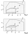
- the Fig. 1 shows a diagram 10, on the abscissa 12 of which the speed of a gasoline engine is plotted increasing according to a directional arrow 14.
- the load of the gasoline engine is plotted increasing according to a directional arrow 18.
- the characteristic map 20 of the gasoline engine is entered into the diagram 10, which serves to illustrate a method for operating the gasoline engine.
- the characteristic map 20 has a first characteristic map area 22 and a second characteristic map area 24.
- the first characteristic map area 22 corresponds to a first operating mode of the gasoline engine, in which the gasoline engine is operated with at least a first valve lift curve.
- the first valve lift curve causes respective first valve lifts of intake valves of the gasoline engine.
- the second characteristic map area 24 corresponds to a second operating mode of the gasoline engine, in which the gasoline engine is operated with at least a second valve lift curve.
- the second valve lift curve causes respective second valve lifts of the intake valves.
- the second valve lifts are smaller than the first valve lifts.
- the intake valves of the gasoline engine are operated by at least one camshaft. This means that the camshaft interacts with the intake valves so that the intake valves - depending on the operating mode - carry out their respective valve strokes and open and close accordingly.
- the camshaft comprises, for example, first cams assigned to the first valve lifts and second cams assigned to the second valve lifts.
- the camshaft interacts with the intake valves via its cams.
- the gasoline engine can be operated either in the first operating mode (first map area 22) or in the second operating mode (second map area 24).
- first map area 22 first map area 22
- second map area 24 second map area 24
- respective Fuel from the gasoline engine is injected directly into combustion chambers, in particular cylinders, of the gasoline engine.
- each of the combustion chambers is assigned at least one injection valve, by means of which fuel is injected directly into the associated combustion chamber.
- At least one of the intake valves is assigned to each combustion chamber. If the intake valves are in an open position, air flowing through an intake tract of the gasoline engine can flow into the respective combustion chambers via intake channels and mix with the fuel injected directly into the combustion chambers. This creates a fuel-air mixture that is ignited and then burns.
- each of the combustion chambers is assigned at least one spark plug, for example, by means of which an ignition spark can be generated.
- the point in time at which the ignition spark is generated and the fuel-air mixture is thereby ignited is referred to as the ignition point.
- the point in time at which the fuel is injected directly into the respective combustion chambers is referred to as the injection point.
- the intake valves open less than in the first operating mode, as they perform the smaller, second valve lifts.
- the intake valves in the second operating mode open up smaller opening cross-sections through which the air can flow into the respective combustion chambers than in the first operating mode.
- the gasoline engine is operated in the second operating mode at predeterminable loads and/or speeds, while the first operating mode is set at higher loads and/or speeds. This means that the gasoline engine is operated in the second operating mode at relatively low speeds and/or loads and in the first operating mode at higher speeds and/or loads. If the speed and/or load exceeds at least one predeterminable threshold value, the system switches from the second operating mode to the first operating mode and vice versa.
- the gasoline engine In the second operating mode, the gasoline engine is operated largely in homogeneous operation, wherein the second characteristic map area 24 has a hysteresis area 26 with regard to load and speed.
- At least one further injection of fuel into the combustion chambers is carried out close to ignition to support the charge movement of the fuel-air mixture in the second operating mode.
- the second characteristic map area 24 has a sub-area 28 in which the internal combustion engine is also operated depending on the load and/or speed and in which the at least one further injection of fuel is carried out directly into the respective combustion chambers before the ignition, in particular shortly before the ignition (close to ignition), of the fuel-air mixture. In other words, a so-called ignition injection is carried out.
- the sub-area 28 also has a hysteresis area 29 with regard to load and speed.
- the system only switches to the second operating mode when a warm-up process for heating up a catalyst in the gasoline engine and warm-up of the gasoline engine have ended. Idle operation and start-stop operation are also carried out in the second operating mode with the lower valve lifts.
- the gasoline engine is preferably assigned at least one exhaust gas turbocharger, by means of which the gasoline engine is supplied with compressed air, i.e. can be charged. This leads to particularly efficient operation of the gasoline engine.
- a load control of the gasoline engine takes place, ie an adjustment of the load of the gasoline engine in the first map area 22, ie in the first operating mode by means of a throttle valve arranged in the intake tract of the gasoline engine or by means of charging by the exhaust gas turbocharger.
- a throttle valve arranged in the intake tract of the gasoline engine or by means of charging by the exhaust gas turbocharger.
- the amount or mass of air flowing into the respective combustion chambers is adjusted by the load.
- the load is adjusted using the throttle valve in a sub-area 30 of the second characteristic map area 24.
- the load is adjusted using the camshaft assigned to the intake valves and referred to as the intake camshaft.
- the load (load control) is adjusted using a waste gate control in the charging area.
- the waste gate control refers to the opening and closing of a valve element, referred to as a waste gate, of a bypass device of the exhaust gas turbocharger.
- the bypass device is assigned to a turbine of the exhaust gas turbocharger and comprises a bypass channel via which exhaust gas from the gasoline engine flowing through the turbine can bypass a turbine wheel of the turbine and thus not drive it.
- the bypass channel can be fluidically blocked and fluidically released by means of the valve element (waste gate). If the bypass channel is fluidically blocked in a closed position of the valve element, exhaust gas cannot flow through the bypass channel. This means that at least substantially all of the exhaust gas drives the turbine wheel. In at least one open position of the valve element, the bypass channel is fluidically released so that the exhaust gas can at least partially bypass the turbine wheel, whereby the exhaust gas bypassing the turbine wheel does not drive the turbine wheel.
- the power of the turbine and thus the pressure of the compressed air to be supplied to the gasoline engine (boost pressure) and in turn the amount or mass of air to be supplied to the gasoline engine can be adjusted.
Landscapes
- Engineering & Computer Science (AREA)
- Chemical & Material Sciences (AREA)
- Combustion & Propulsion (AREA)
- Mechanical Engineering (AREA)
- General Engineering & Computer Science (AREA)
- Output Control And Ontrol Of Special Type Engine (AREA)
- Electrical Control Of Air Or Fuel Supplied To Internal-Combustion Engine (AREA)
- Combined Controls Of Internal Combustion Engines (AREA)
Claims (4)
- Procédé permettant de faire fonctionner un moteur à combustion interne, réalisé sous forme de moteur à étincelles, d'un véhicule automobile, dans lequel au moins une injection de carburant est effectuée directement dans au moins une chambre de combustion du moteur à combustion interne au moyen d'au moins un dispositif d'injection et un allumage d'un mélange du carburant et d'air dans la chambre de combustion est effectué au moyen d'un dispositif d'allumage, dans lequel le moteur à combustion interne fonctionne au choix dans au moins un premier mode de fonctionnement (22) comportant au moins une première levée de soupape d'au moins une soupape d'échange de gaz du moteur à combustion interne associée à la chambre de combustion ou dans au moins un second mode de fonctionnement (24) comportant au moins une seconde levée de soupape de la soupape d'échange de gaz qui est inférieure à la première levée de soupape, et
pour la prise en charge d'un déplacement de charge du mélange dans le second mode de fonctionnement, au moins une autre injection de carburant est effectuée directement dans la chambre de combustion temporellement avant l'allumage, caractérisé en ce que, dans le second mode de fonctionnement, le moteur à combustion interne fonctionne au moins en grande partie dans un fonctionnement homogène dans lequel le mélange est particulièrement homogène par rapport à un éventuel fonctionnement de charge en mode stratifié du moteur à combustion interne, dans lequel une charge du moteur à combustion interne est réglée dans une première plage de charge (30) du second mode de fonctionnement au moyen d'un papillon des gaz, dans une deuxième plage de charge (32) du second mode de fonctionnement par l'intermédiaire d'un arbre à cames qui est associé à au moins une soupape d'admission associée à la chambre de combustion, et dans une troisième plage de charge (34) du second mode de fonctionnement par l'intermédiaire d'une commande de soupape de décharge dans la zone de suralimentation. - Procédé selon la revendication 1, caractérisé en ce que
l'autre injection est effectuée temporellement après l'au moins une première injection. - Procédé selon l'une des revendications 1 ou 2,
caractérisé en ce que
dans le second mode de fonctionnement, un allumage à plus d'étincelles que l'allumage est effectué. - Procédé selon l'une des revendications précédentes,
caractérisé en ce que
le moteur à combustion interne fonctionne dans le second mode de fonctionnement lorsqu'au moins une valeur caractérisant au moins une température du moteur à combustion interne dépasse une valeur seuil pouvant être prédéfinie.
Applications Claiming Priority (2)
| Application Number | Priority Date | Filing Date | Title |
|---|---|---|---|
| DE102012006342A DE102012006342A1 (de) | 2012-03-28 | 2012-03-28 | Verfahren zum Betreiben einer Verbrennungskraftmaschine |
| PCT/EP2013/000907 WO2013143687A1 (fr) | 2012-03-28 | 2013-03-26 | Procédé pour faire fonctionner un moteur à combustion interne |
Publications (3)
| Publication Number | Publication Date |
|---|---|
| EP2831400A1 EP2831400A1 (fr) | 2015-02-04 |
| EP2831400B1 true EP2831400B1 (fr) | 2025-02-19 |
| EP2831400C0 EP2831400C0 (fr) | 2025-02-19 |
Family
ID=48182876
Family Applications (1)
| Application Number | Title | Priority Date | Filing Date |
|---|---|---|---|
| EP13718296.0A Active EP2831400B1 (fr) | 2012-03-28 | 2013-03-26 | Procédé pour faire fonctionner un moteur à combustion interne |
Country Status (6)
| Country | Link |
|---|---|
| US (1) | US10337415B2 (fr) |
| EP (1) | EP2831400B1 (fr) |
| JP (1) | JP2015512482A (fr) |
| CN (1) | CN104204483B (fr) |
| DE (1) | DE102012006342A1 (fr) |
| WO (1) | WO2013143687A1 (fr) |
Families Citing this family (3)
| Publication number | Priority date | Publication date | Assignee | Title |
|---|---|---|---|---|
| DE102017206266A1 (de) * | 2017-04-12 | 2018-10-18 | Volkswagen Aktiengesellschaft | Verfahren zum Betreiben einer Brennkraftmaschine und Brennkraftmaschine |
| DE102018208000A1 (de) * | 2018-05-22 | 2019-11-28 | Bayerische Motoren Werke Aktiengesellschaft | Verbrennungskraftmaschine für ein Kraftfahrzeug, insbesondere für einen Kraftwagen, sowie Verfahren zum Betreiben einer solchen Verbrennungskraftmaschine |
| US11125203B1 (en) * | 2020-10-13 | 2021-09-21 | Fca Us Llc | Multi-strike ignition during variable valve lift camshaft profile switching |
Citations (3)
| Publication number | Priority date | Publication date | Assignee | Title |
|---|---|---|---|---|
| EP1484494A2 (fr) * | 2003-06-03 | 2004-12-08 | Hitachi, Ltd. | Dispositif et procédé de commande d'injection multiple et de soupapes à distribution variable dans un moteur à injection directe |
| WO2006063372A1 (fr) * | 2004-12-16 | 2006-06-22 | Avl List Gmbh | Procede pour faire fonctionner un moteur a combustion interne |
| EP1840357A2 (fr) * | 2006-03-31 | 2007-10-03 | Mazda Motor Corporation | Moteur essence à allumage commandé |
Family Cites Families (24)
| Publication number | Priority date | Publication date | Assignee | Title |
|---|---|---|---|---|
| JPS5529028A (en) | 1978-08-19 | 1980-03-01 | Nippon Soken Inc | Igniting of engine |
| JPH02146264A (ja) | 1988-11-29 | 1990-06-05 | Fuji Heavy Ind Ltd | エンジンの点火時期制御装置 |
| JPH03279649A (ja) * | 1990-03-27 | 1991-12-10 | Mazda Motor Corp | エンジンの点火装置 |
| WO1997013063A1 (fr) * | 1995-10-02 | 1997-04-10 | Hitachi, Ltd. | Dispositif de commande pour moteur a combustion interne |
| JP3804126B2 (ja) * | 1996-11-07 | 2006-08-02 | 日産自動車株式会社 | 機械式過給機付きエンジンの制御装置 |
| DE19936201A1 (de) * | 1999-07-31 | 2001-02-08 | Bosch Gmbh Robert | Verfahren zum Betreiben einer Brennkraftmaschine |
| DE10242226A1 (de) | 2002-09-12 | 2004-03-25 | Daimlerchrysler Ag | Verfahren zum Betrieb einer fremdgezündeten Brennkraftmaschine |
| DE10341070B4 (de) * | 2003-09-05 | 2006-07-27 | Siemens Ag | Verfahren und Vorrichtung zur Steuerung des Übergangs von einer ersten Betriebsart eines mit Kraftstoff-Direkteinspritzung betriebenen Ottomotors auf eine zweite Betriebsart |
| DE102004061142B4 (de) | 2004-12-20 | 2008-10-16 | Audi Ag | Verfahren und Vorrichtung zur Steuerung eines Verbrennungsmotors |
| ITTO20060563A1 (it) * | 2006-07-28 | 2008-01-29 | Eaton Srl | Dispositivo di comando alzata per una valvola a stelo di motore a combustione interna o macchina operatrice |
| JP4552922B2 (ja) * | 2006-10-26 | 2010-09-29 | トヨタ自動車株式会社 | 筒内噴射式火花点火内燃機関 |
| JP4850744B2 (ja) | 2007-02-13 | 2012-01-11 | 日立オートモティブシステムズ株式会社 | 内燃機関の吸気制御装置 |
| US8096108B2 (en) * | 2007-05-01 | 2012-01-17 | GM Global Technology Operations LLC | Engine warm-up of a homogeneous charge compression ignition engine |
| JP2009019538A (ja) | 2007-07-11 | 2009-01-29 | Denso Corp | 筒内噴射式内燃機関の制御装置 |
| US7975672B2 (en) * | 2007-08-17 | 2011-07-12 | GM Global Technology Operations LLC | Method for controlling engine intake airflow |
| US7974766B2 (en) * | 2007-09-07 | 2011-07-05 | GM Gobal Technology Operations LLC | Valvetrain control systems with lift mode transitioning based engine synchronization timing and sensor based lift mode control |
| JP4858397B2 (ja) * | 2007-10-15 | 2012-01-18 | 株式会社豊田自動織機 | 予混合圧縮着火機関 |
| JP4788797B2 (ja) * | 2009-03-31 | 2011-10-05 | マツダ株式会社 | 過給機付き直噴エンジン |
| KR101189229B1 (ko) * | 2009-11-12 | 2012-10-09 | 현대자동차주식회사 | 압축 착화 가솔린 엔진 |
| US8312849B2 (en) * | 2009-12-15 | 2012-11-20 | Delphi Technologies, Inc. | Dual intake valve system with one deactivation valve and one multi-lift valve for swirl enhancement |
| DE102010012127B3 (de) * | 2010-03-20 | 2011-07-07 | Dr. Ing. h.c. F. Porsche Aktiengesellschaft, 70435 | Verfahren zum Betreiben eines Verbrennungsmotors |
| US9022003B2 (en) * | 2011-04-06 | 2015-05-05 | GM Global Technology Operations LLC | Piston for robust auto-ignition |
| US9512793B2 (en) * | 2012-10-16 | 2016-12-06 | GM Global Technology Operations LLC | Combustion driven ammonia generation strategies for passive ammonia SCR system |
| US9181825B2 (en) * | 2013-04-23 | 2015-11-10 | Edward Hall Batchelor, JR. | Internal combustion engine independent valve actuator |
-
2012
- 2012-03-28 DE DE102012006342A patent/DE102012006342A1/de active Pending
-
2013
- 2013-03-26 JP JP2015502137A patent/JP2015512482A/ja active Pending
- 2013-03-26 US US14/388,321 patent/US10337415B2/en active Active
- 2013-03-26 WO PCT/EP2013/000907 patent/WO2013143687A1/fr not_active Ceased
- 2013-03-26 CN CN201380016744.6A patent/CN104204483B/zh active Active
- 2013-03-26 EP EP13718296.0A patent/EP2831400B1/fr active Active
Patent Citations (3)
| Publication number | Priority date | Publication date | Assignee | Title |
|---|---|---|---|---|
| EP1484494A2 (fr) * | 2003-06-03 | 2004-12-08 | Hitachi, Ltd. | Dispositif et procédé de commande d'injection multiple et de soupapes à distribution variable dans un moteur à injection directe |
| WO2006063372A1 (fr) * | 2004-12-16 | 2006-06-22 | Avl List Gmbh | Procede pour faire fonctionner un moteur a combustion interne |
| EP1840357A2 (fr) * | 2006-03-31 | 2007-10-03 | Mazda Motor Corporation | Moteur essence à allumage commandé |
Also Published As
| Publication number | Publication date |
|---|---|
| DE102012006342A1 (de) | 2013-10-02 |
| EP2831400C0 (fr) | 2025-02-19 |
| CN104204483A (zh) | 2014-12-10 |
| EP2831400A1 (fr) | 2015-02-04 |
| US10337415B2 (en) | 2019-07-02 |
| CN104204483B (zh) | 2017-11-17 |
| JP2015512482A (ja) | 2015-04-27 |
| US20150047600A1 (en) | 2015-02-19 |
| WO2013143687A1 (fr) | 2013-10-03 |
Similar Documents
| Publication | Publication Date | Title |
|---|---|---|
| DE102013013620B4 (de) | Funkenzündungs-Direkteinspritzungsmotor, Steuereinrichtung für diesen, Verfahren zum Steuern eines Motors und Computerprogrammprodukt | |
| DE102013013619B4 (de) | Funkenzündungs-Direkteinspritzungsmotor, Verfahren zum Steuern eines Funkenzündungs-Direkteinspritzungsmotors und Computerprogrammprodukt | |
| DE102013014412B4 (de) | Funkenzündungs-Direkteinspritzungsmotor, Verfahren eines Betreibens eines Funkenzündungs-Direkteinspritzungsmotors und Computerprogrammprodukt | |
| DE112012003727B4 (de) | Benzineinspritzmotor und Verfahren zur Kontrolle des Benzineinspritzmotors | |
| DE112013004282B4 (de) | Fremdgezündeter Direkteinspritzmotor | |
| DE69925502T2 (de) | Verfahren zur regelung der verbrennung in einer brennkraftmaschine und motor mit vorrichtung zur regelung der gaswechselventile | |
| DE102013013527B4 (de) | Funkenzündungs-direkteinspritzungsmotor | |
| DE102007056216B4 (de) | Verfahren und Steuergerät zum beschleunigten Aufheizen eines Katalysators im Abgassystem eines aufgeladenen Verbrennungsmotors mit variabler Ventilsteuerung | |
| DE102008042835B4 (de) | Maschine mit Kompressionszündung mit homogener Ladung und Steuerverfahren der Maschine | |
| DE112014004936B4 (de) | Steuervorrichtung für Kompressionszündungsmotor | |
| DE102014013884B4 (de) | Kompressionszündungsmotor, Regel- bzw. Steuervorrichtung hierfür, Verfahren zum Regeln bzw. Steuern eines Motors und Computerprogrammprodukt | |
| DE112012003878B4 (de) | Steuersystem und Steuerverfahren eines Ottomotors | |
| DE102016008911A1 (de) | Mit Vormischungsbeschickung und Kompressionszündung arbeitender Motor, Steuer- bzw. Regeleinrichtung hierfür, Verfahren zum Steuern bzw. Regeln eines Motors und Computerprogrammerzeugnis | |
| DE102014013880A1 (de) | Kompressionszündungsmotor, Regel- bzw. Steuervorrichtung für einen Motor, Verfahren zum Regeln bzw. Steuern einer Kraftstoffunterbrechung und Computerprogrammprodukt | |
| DE112006001046T5 (de) | HCCI- und SI-Verbrennungssteuerungsverfahren für eine Brennkraftmaschine mit Direkteinspritzung | |
| DE112005001819T5 (de) | Ventil- und Kraftstoffbeaufschlagungsstrategie zum Betreiben eines Viertakt-Verbrennungsmotors mit gesteuerter Selbstzündung | |
| EP1276980A1 (fr) | Procede pour commander le remplissage des cylindres dans un moteur a combustion interne | |
| DE102014002893A1 (de) | Funkenzündungsmotor, Regel- bzw. Steuervorrichtung dafür, Verfahren zum Regeln bzw. Steuern eines Motors und Computerprogrammprodukt | |
| DE102016010309B4 (de) | Direkteinspritzender Verbrennungsmotor, Steuervorrichtung für einen derartigen Motor, Verfahren zum Steuern eines Motors und Computerprogrammprodukt | |
| DE102015016972B4 (de) | Verbrennungsmotor, Regel- bzw. Steuervorrichtung für einen Motor, Verfahren zum Regeln bzw. Steuern eines Motors und Computerprogrammprodukt | |
| DE10350798B4 (de) | Verfahren zum Betrieb einer Brennkraftmaschine | |
| DE102017208857A1 (de) | Verfahren zum Betreiben einer Brennkraftmaschine, Brennkraftmaschine und Kraftfahrzeug | |
| EP2831400B1 (fr) | Procédé pour faire fonctionner un moteur à combustion interne | |
| EP1703112B1 (fr) | Procédé de chauffage d'un catalyseur d'un moteur à combustion interne | |
| EP1338776B1 (fr) | Moteur à quatre temps à allumage commandé avec deux arbres à cames à phase variable et sa méthode de commande |
Legal Events
| Date | Code | Title | Description |
|---|---|---|---|
| PUAI | Public reference made under article 153(3) epc to a published international application that has entered the european phase |
Free format text: ORIGINAL CODE: 0009012 |
|
| 17P | Request for examination filed |
Effective date: 20140812 |
|
| AK | Designated contracting states |
Kind code of ref document: A1 Designated state(s): AL AT BE BG CH CY CZ DE DK EE ES FI FR GB GR HR HU IE IS IT LI LT LU LV MC MK MT NL NO PL PT RO RS SE SI SK SM TR |
|
| AX | Request for extension of the european patent |
Extension state: BA ME |
|
| DAX | Request for extension of the european patent (deleted) | ||
| RAP1 | Party data changed (applicant data changed or rights of an application transferred) |
Owner name: DAIMLER AG |
|
| STAA | Information on the status of an ep patent application or granted ep patent |
Free format text: STATUS: EXAMINATION IS IN PROGRESS |
|
| 17Q | First examination report despatched |
Effective date: 20210317 |
|
| RAP3 | Party data changed (applicant data changed or rights of an application transferred) |
Owner name: MERCEDES-BENZ GROUP AG |
|
| GRAP | Despatch of communication of intention to grant a patent |
Free format text: ORIGINAL CODE: EPIDOSNIGR1 |
|
| STAA | Information on the status of an ep patent application or granted ep patent |
Free format text: STATUS: GRANT OF PATENT IS INTENDED |
|
| RIC1 | Information provided on ipc code assigned before grant |
Ipc: F02P 15/08 20060101ALI20240723BHEP Ipc: F02D 41/40 20060101ALI20240723BHEP Ipc: F02D 41/00 20060101ALI20240723BHEP Ipc: F02B 17/00 20060101ALI20240723BHEP Ipc: F02D 13/02 20060101ALI20240723BHEP Ipc: F02D 41/30 20060101AFI20240723BHEP |
|
| INTG | Intention to grant announced |
Effective date: 20240816 |
|
| GRAS | Grant fee paid |
Free format text: ORIGINAL CODE: EPIDOSNIGR3 |
|
| GRAA | (expected) grant |
Free format text: ORIGINAL CODE: 0009210 |
|
| STAA | Information on the status of an ep patent application or granted ep patent |
Free format text: STATUS: THE PATENT HAS BEEN GRANTED |
|
| AK | Designated contracting states |
Kind code of ref document: B1 Designated state(s): AL AT BE BG CH CY CZ DE DK EE ES FI FR GB GR HR HU IE IS IT LI LT LU LV MC MK MT NL NO PL PT RO RS SE SI SK SM TR |
|
| REG | Reference to a national code |
Ref country code: GB Ref legal event code: FG4D Free format text: NOT ENGLISH |
|
| REG | Reference to a national code |
Ref country code: CH Ref legal event code: EP |
|
| REG | Reference to a national code |
Ref country code: DE Ref legal event code: R096 Ref document number: 502013016572 Country of ref document: DE |
|
| REG | Reference to a national code |
Ref country code: IE Ref legal event code: FG4D Free format text: LANGUAGE OF EP DOCUMENT: GERMAN |
|
| U01 | Request for unitary effect filed |
Effective date: 20250313 |
|
| U07 | Unitary effect registered |
Designated state(s): AT BE BG DE DK EE FI FR IT LT LU LV MT NL PT RO SE SI Effective date: 20250319 |
|
| U20 | Renewal fee for the european patent with unitary effect paid |
Year of fee payment: 13 Effective date: 20250325 |
|
| PG25 | Lapsed in a contracting state [announced via postgrant information from national office to epo] |
Ref country code: RS Free format text: LAPSE BECAUSE OF FAILURE TO SUBMIT A TRANSLATION OF THE DESCRIPTION OR TO PAY THE FEE WITHIN THE PRESCRIBED TIME-LIMIT Effective date: 20250519 |
|
| PG25 | Lapsed in a contracting state [announced via postgrant information from national office to epo] |
Ref country code: PL Free format text: LAPSE BECAUSE OF FAILURE TO SUBMIT A TRANSLATION OF THE DESCRIPTION OR TO PAY THE FEE WITHIN THE PRESCRIBED TIME-LIMIT Effective date: 20250219 |
|
| PG25 | Lapsed in a contracting state [announced via postgrant information from national office to epo] |
Ref country code: ES Free format text: LAPSE BECAUSE OF FAILURE TO SUBMIT A TRANSLATION OF THE DESCRIPTION OR TO PAY THE FEE WITHIN THE PRESCRIBED TIME-LIMIT Effective date: 20250219 |
|
| PG25 | Lapsed in a contracting state [announced via postgrant information from national office to epo] |
Ref country code: IS Free format text: LAPSE BECAUSE OF FAILURE TO SUBMIT A TRANSLATION OF THE DESCRIPTION OR TO PAY THE FEE WITHIN THE PRESCRIBED TIME-LIMIT Effective date: 20250619 Ref country code: NO Free format text: LAPSE BECAUSE OF FAILURE TO SUBMIT A TRANSLATION OF THE DESCRIPTION OR TO PAY THE FEE WITHIN THE PRESCRIBED TIME-LIMIT Effective date: 20250519 |
|
| PG25 | Lapsed in a contracting state [announced via postgrant information from national office to epo] |
Ref country code: HR Free format text: LAPSE BECAUSE OF FAILURE TO SUBMIT A TRANSLATION OF THE DESCRIPTION OR TO PAY THE FEE WITHIN THE PRESCRIBED TIME-LIMIT Effective date: 20250219 |
|
| PG25 | Lapsed in a contracting state [announced via postgrant information from national office to epo] |
Ref country code: GR Free format text: LAPSE BECAUSE OF FAILURE TO SUBMIT A TRANSLATION OF THE DESCRIPTION OR TO PAY THE FEE WITHIN THE PRESCRIBED TIME-LIMIT Effective date: 20250520 |
|
| PG25 | Lapsed in a contracting state [announced via postgrant information from national office to epo] |
Ref country code: SM Free format text: LAPSE BECAUSE OF FAILURE TO SUBMIT A TRANSLATION OF THE DESCRIPTION OR TO PAY THE FEE WITHIN THE PRESCRIBED TIME-LIMIT Effective date: 20250219 |
|
| PG25 | Lapsed in a contracting state [announced via postgrant information from national office to epo] |
Ref country code: CZ Free format text: LAPSE BECAUSE OF FAILURE TO SUBMIT A TRANSLATION OF THE DESCRIPTION OR TO PAY THE FEE WITHIN THE PRESCRIBED TIME-LIMIT Effective date: 20250219 |
|
| REG | Reference to a national code |
Ref country code: CH Ref legal event code: H13 Free format text: ST27 STATUS EVENT CODE: U-0-0-H10-H13 (AS PROVIDED BY THE NATIONAL OFFICE) Effective date: 20251023 |
|
| PG25 | Lapsed in a contracting state [announced via postgrant information from national office to epo] |
Ref country code: SK Free format text: LAPSE BECAUSE OF FAILURE TO SUBMIT A TRANSLATION OF THE DESCRIPTION OR TO PAY THE FEE WITHIN THE PRESCRIBED TIME-LIMIT Effective date: 20250219 |
|
| PG25 | Lapsed in a contracting state [announced via postgrant information from national office to epo] |
Ref country code: MC Free format text: LAPSE BECAUSE OF FAILURE TO SUBMIT A TRANSLATION OF THE DESCRIPTION OR TO PAY THE FEE WITHIN THE PRESCRIBED TIME-LIMIT Effective date: 20250219 |
|
| PLBE | No opposition filed within time limit |
Free format text: ORIGINAL CODE: 0009261 |
|
| STAA | Information on the status of an ep patent application or granted ep patent |
Free format text: STATUS: NO OPPOSITION FILED WITHIN TIME LIMIT |
|
| PG25 | Lapsed in a contracting state [announced via postgrant information from national office to epo] |
Ref country code: CH Free format text: LAPSE BECAUSE OF NON-PAYMENT OF DUE FEES Effective date: 20250331 |
|
| PG25 | Lapsed in a contracting state [announced via postgrant information from national office to epo] |
Ref country code: IE Free format text: LAPSE BECAUSE OF NON-PAYMENT OF DUE FEES Effective date: 20250326 |
|
| 26N | No opposition filed |
Effective date: 20251120 |
|
| GBPC | Gb: european patent ceased through non-payment of renewal fee |
Effective date: 20250519 |
|
| PG25 | Lapsed in a contracting state [announced via postgrant information from national office to epo] |
Ref country code: GB Free format text: LAPSE BECAUSE OF NON-PAYMENT OF DUE FEES Effective date: 20250519 |