EP2831804B1 - Système et procédé pour le raffinement de réseau local automatique dans des systèmes de simulation de réservoir - Google Patents
Système et procédé pour le raffinement de réseau local automatique dans des systèmes de simulation de réservoir Download PDFInfo
- Publication number
- EP2831804B1 EP2831804B1 EP12873117.1A EP12873117A EP2831804B1 EP 2831804 B1 EP2831804 B1 EP 2831804B1 EP 12873117 A EP12873117 A EP 12873117A EP 2831804 B1 EP2831804 B1 EP 2831804B1
- Authority
- EP
- European Patent Office
- Prior art keywords
- grid
- computer
- formation
- reservoir
- local region
- Prior art date
- Legal status (The legal status is an assumption and is not a legal conclusion. Google has not performed a legal analysis and makes no representation as to the accuracy of the status listed.)
- Active
Links
Images


Classifications
-
- G—PHYSICS
- G01—MEASURING; TESTING
- G01V—GEOPHYSICS; GRAVITATIONAL MEASUREMENTS; DETECTING MASSES OR OBJECTS; TAGS
- G01V20/00—Geomodelling in general
-
- G—PHYSICS
- G01—MEASURING; TESTING
- G01V—GEOPHYSICS; GRAVITATIONAL MEASUREMENTS; DETECTING MASSES OR OBJECTS; TAGS
- G01V1/00—Seismology; Seismic or acoustic prospecting or detecting
- G01V1/28—Processing seismic data, e.g. for interpretation or for event detection
- G01V1/30—Analysis
-
- G—PHYSICS
- G01—MEASURING; TESTING
- G01V—GEOPHYSICS; GRAVITATIONAL MEASUREMENTS; DETECTING MASSES OR OBJECTS; TAGS
- G01V1/00—Seismology; Seismic or acoustic prospecting or detecting
- G01V1/28—Processing seismic data, e.g. for interpretation or for event detection
- G01V1/30—Analysis
- G01V1/301—Analysis for determining seismic cross-sections or geostructures
- G01V1/302—Analysis for determining seismic cross-sections or geostructures in 3D data cubes
-
- G—PHYSICS
- G01—MEASURING; TESTING
- G01V—GEOPHYSICS; GRAVITATIONAL MEASUREMENTS; DETECTING MASSES OR OBJECTS; TAGS
- G01V9/00—Prospecting or detecting by methods not provided for in groups G01V1/00 - G01V8/00
- G01V9/005—Prospecting or detecting by methods not provided for in groups G01V1/00 - G01V8/00 by thermal methods, e.g. after generation of heat by chemical reactions
-
- G—PHYSICS
- G06—COMPUTING OR CALCULATING; COUNTING
- G06F—ELECTRIC DIGITAL DATA PROCESSING
- G06F30/00—Computer-aided design [CAD]
- G06F30/20—Design optimisation, verification or simulation
-
- G—PHYSICS
- G06—COMPUTING OR CALCULATING; COUNTING
- G06F—ELECTRIC DIGITAL DATA PROCESSING
- G06F30/00—Computer-aided design [CAD]
- G06F30/20—Design optimisation, verification or simulation
- G06F30/28—Design optimisation, verification or simulation using fluid dynamics, e.g. using Navier-Stokes equations or computational fluid dynamics [CFD]
-
- G—PHYSICS
- G01—MEASURING; TESTING
- G01V—GEOPHYSICS; GRAVITATIONAL MEASUREMENTS; DETECTING MASSES OR OBJECTS; TAGS
- G01V2210/00—Details of seismic processing or analysis
- G01V2210/60—Analysis
- G01V2210/66—Subsurface modeling
Definitions
- Reservoir simulation is an area of reservoir engineering that employs computer models to predict the transport of fluids, such as petroleum, water, and gas, within a reservoir.
- Reservoir simulators are used by petroleum producers in determining how best to develop new fields, as well as generate production forecasts on which investment decisions can be based in connection with developed fields.
- Reservoir simulation software models are typically implemented using a number of discretized blocks, referred to interchangeably herein as "blocks,” “grid blocks,” or “cells.” Models can vary in size from a few blocks to hundreds of millions of blocks. In these software simulations, it is common to model a reservoir using a grid formed of grid blocks and then simulate reservoir properties (e.g., pressure, temperature) within each grid block to predict flow. For example, such modeling is particularly useful in low permeability reservoirs for determining how many and where fractures should be induced in a reservoir to achieve a certain flow over a period of time.
- reservoir properties e.g., pressure, temperature
- shale reservoirs have extremely low permeability when compared to other types of geologic reservoirs.
- shale reservoirs may be less permeable than other geologic reservoirs by a factor of 10 -6 .
- flow in a portions of shale reservoir must be modeled at a very fine grid scale when compared to non-shale reservoirs, which may often be modeled with coarser grids, i.e., grid with larger grid blocks.
- LGRs local grid refinements
- US 2009/0119082 A1 describes a reservoir fracture simulation method including defining a coarse cell grid and building a fine scale model, based on smaller cells inside the coarse cells and around the fracture.
- US2010/0076738 A1 (D2) describes a method for modeling a geomechanical reservoir system, including defining a finer cell grid on a previously defined coarse grid and defining a time period and a time step for determining the porosity.
- a computer-implemented reservoir simulation system comprising: a processor; a non-transitory, computer-readable storage medium accessible by the processor; and software instructions stored on the storage medium and executable by the processor for carrying out the computer-implemented method according to the first aspect of the present invention.
- a method for drilling a wellbore in reservoir comprising: applying a coarse grid to a geologic formation of interest, the coarse grid having a plurality of coarse grid blocks; identifying a structure of interest disposed in the formation; determining a fine grid zone around the structure based upon a time period for flow simulation of the geologic formation and a geologic characteristic of the geologic formation in a local region adjacent the structure; applying a fine grid to the coarse grid blocks encompassed by the fine grid zone to determine flow adjacent the structure; based on the determined flow, selecting a position and trajectory for a wellbore in the formation; preparing equipment to construct a portion of said wellbore; and drilling a wellbore in accordance with the selected trajectory, wherein determining the fine grid zone includes calculating a distance X val away from the structure at which the fine grid zone terminates, the calculating based upon the time period for flow simulation and the geologic characteristic, and wherein the calculating the distance X val
- one or more embodiments described herein comprise a method of automatic local grid refinements in reservoir simulation models.
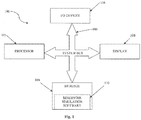
- Fig. 1 is a block diagram of an exemplary computer system 100 adapted for implementing the reservoir simulation system as described herein.
- the computer system 100 includes at least one processor 102, a non-transitory, computer-readable storage 104, optional I/O devices 106, and an optional display 108, all interconnected via a system bus 109.
- Software instructions executable by the processor 102 for implementing a reservoir simulation system 110 in accordance with the embodiments described herein, may be stored in storage 104.
- the computer system 100 may be connected to one or more public and/or private networks via appropriate network connections.
- the software instructions comprising the reservoir simulation system 110 may be loaded into storage 104 from a CD-ROM or other appropriate storage media.
- a portion of the reservoir simulation system 110 is implemented using reservoir simulation software known in the art.
- reservoir simulation software typically utilizes numerical representations of the reservoir , either as it currently exists or as it is envisioned to exist at some point in the future once, such as before any wells are drilled and prior to any field development.
- This representation of the reservoir combined with additional data about proposed or existing wells and development strategy allows the software to predict how the reservoir might perform in terms of fluid injection and production.
- LGRs local grid refinements
- the size of an LGR in the prior art has been defined based on simulation data.
- an engineer may have had to manually define the LGR or LGR characteristics in the reservoir simulation software.
- a method for automatically applying an appropriately-sized LGR to an area of interest determines the distance from a geologic structure, such as a fracture, that a fine grid should extend so as to minimize the unnecessary application of fine grids in a reservoir simulation model.
- the method utilizes the reservoir parameters of porosity and permeability in conjunction with formation flow over a select period of time to automatically generate appropriately-sized and spaced LGRs for modeling flow over the time period.
- the reservoir simulation system 110 in the computer system 100 may implement this method and other methods contemplated by the embodiment.
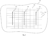
- Fig. 3 illustrates a reservoir 300 that will be modeled by method 200.
- the reservoir 300 is an extremely low permeability shale reservoir, but in other embodiments, may be other types of formations.
- the reservoir 300 includes one or more geologic features of interest, such as fractures, wellbores or the like.
- fractures 302, 304, and 306 are shown.
- a model of reservoir 300 should ultimately predict the areas of the reservoir in which fluid and/or pressure movement associated with the fractures will occur.
- these fractures may be either man-made or naturally occurring. In other embodiments, they may be other types of reservoir features that are of interest.
- a coarse grid 308 is applied to the reservoir 300.
- the coarse grid 308 is characterized by a multiplicity of coarse grid blocks 310.
- grid blocks 310 may be substantially uniform in shape and size, but the particular shape and size of grid blocks as described in the invention is not intended as a limitation.
- each of the coarse grid blocks 310 is used to discretely characterize a portion of the reservoir 300.
- reservoir engineering data may be collected on a grid block level.
- each grid block 310 in the coarse grid 308 may be associated with a distinct porosity value and a distinct permeability value.
- a functional model of the reservoir 300 may be created by simulating reservoir properties such as pressure and temperature within each grid block.
- the embodiment is not limited to a grid defined in one plane.
- all of the methods described herein are also valid in other dimensions, such as three dimensions ("3D").
- the grid blocks do not need to be of any particular shape.
- the grid blocks are shown as rectangular.
- use of the terms "standard” grid block and "non-standard” grid block refers to the shape of the grid block of interest when compared to the common shape of a plurality of blocks in a grid.
- a grid may be generally characterized by a plurality of rectangular grid blocks of a particular dimension w, h and l (where w, h and l are width, length and height respectively), thereby representing the "standard" shape of blocks for a grid.
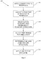
- a structure of interest in the reservoir 300 is identified.
- the structure identified in step 204 may be an existing structure in an existing formation or it may be a proposed structure selected to achieve a particular flow in a modeled formation.
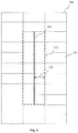
- the identified structure is a fracture, for example fracture 304, as shown in more detail in Fig. 4 .
- a model is used to simulate pressure flow at a large number of discrete locations around the fracture.
- the coarse grid blocks 310 of coarse grid 308 may have a width 312 that is too large to produce an accurate simulation of the fracture's pressure change.
- an LGR is needed to replace the coarse grid blocks 310 in the areas surrounding the fracture 304.
- the application of an appropriately-sized LGR to fracture 304 is described in associated with the remaining steps of Fig. 2 .
- the porosity and permeability for the region surrounding the fracture 304 are selected. Porosity and permeability may be selected based on known data for the reservoir or expected or estimated data for the reservoir.
- this step includes two sub-steps. First, the size of the local region around the fracture 304 in which average permeability and porosity is identified. Second, average values for permeability and porosity for the local region are determined. In Fig. 5 , for example, a local region 314 around fracture 304 is shown. In certain embodiment, system 110 automatically determines the size the local region 314 based on the distances 316 and 318 between fracture 304 and the adjacent fractures 302 and 306 in reservoir 300. In the illustrated embodiment, the left-most outer boundary of local region 314 is approximately mid-way between the fracture 302 and fracture 304, and the rightmost boundary is approximately mid-way between fracture 306 and fracture 304.
- the local region 314 would extend approximately 76 meters (250 feet) away from fracture 304 in the direction of fracture 302. Further, the local region 314 may extend in the y-direction, and as applicable, the z-direction, away from fracture 304 depending on the distance to a reservoir boundary, another fracture, or some other structure.
- the local region surrounding a structure of interest in a reservoir may be determined in any number of various ways and the above determination is simply an example. For instance, in alternative embodiments, a local region may extend less than halfway between a fracture of interest and an adjacent fracture.
- the average permeability and average porosity for the local region are determined.
- geologic engineering data collected by reservoir tools is associated with each grid block 310 in the coarse grid 308. That is, each grid block within the local region 314 has a discrete permeability value and a discrete porosity value.
- the average permeability values of the grid blocks within the local region 314 are determined to find overall permeability of the local region and the average porosity values of the grid blocks within the local region 314 are determined to find the overall porosity of the local region.
- the permeability of the local region 314 is measured in millidarcies (mD) and the porosity is a value between 0 and 1 that represents a ratio of the pore volume over the total volume.
- mD millidarcies
- a grid block is considered to be within the region for the purposes of the permeability and porosity calculations if a greater percentage of it is inside the local region than outside the local region.
- a time period for the simulation of the movement of pressure in the reservoir 300 is selected. For example, it may be desirable to predict flow of a formation over a one year period, or perhaps over an extended period, such as 20 years. In some instances, the time period selected depends on the predicted number of years a reservoir will be producing oil and/or gas. In the present embodiment, a time period is selected in days, however, in other embodiment, different time units may be utilized.
- Fig. 6 illustrates a fine grid zone 320 around the fracture 304.
- fine grid zone 320 extends a distance 322 in the x-direction from fracture.
- the local permeability and local porosity identified in step 206 and the simulation time period selected in step 208 are utilized to calculate distance 322.
- the local permeability and porosity values upon which the distance 322 is based are measured engineering data rather than variables estimated via a simulation.
- the distance X val 322 is applied to the coarse grid 308 to determine the number of coarse grid blocks 310 away from the fracture that will be encompassed by the fine grid zone 320.
- the calculated distance 322 may be applied in any direction from the structure. In the illustrated embodiment of Fig. 6 , the calculated distance 322 is applied in the x direction from the fracture 304 so as to define the fine grid zone 320. In an alternate and complementary embodiment, the distance X val may also be applied in the y- direction and/or the z-direction.
- the entire grid block is included in the fine grid zone if the center point of the grid block is less than the distance X val away from the fracture.
- a grid block need not be included in the fine grid zone if its center point is greater than the distance X val away from the fracture.
- at least one partial grid block may be included in the fine grid zone. In this manner, it is determined which grid blocks in the coarse grid 308 should be refined into smaller grid blocks so as to increase the accuracy of the reservoir simulation in the regions around a fracture.
- a local grid refinement is applied to the fine grid zone 320 determined in step 210. That is, each coarse grid block within the fine grid zone 320 is sub-divided into a plurality of smaller (i.e., finer) grid blocks.
- the coarse grid blocks designated for refinement may be subdivided using any standard gridding algorithm known in the art. For example, a standard gridding algorithm may be applied to create an LGR around the fracture with uniformly-sized fine grid blocks.
- a geometric gridding algorithm may be utilized to create a LGR with fine grid blocks that geometrically increase in size as their distance away from the structure of interest increases. That is, in geometric LGRs, each grid block varies in size from an adjacent grid block in a direction by a constant factor.
- any number of different and/or additional grid refinements may be applied to the fine grid zone.
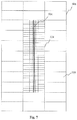
- Fig. 7 illustrates the application of an LGR 324 to the coarse grid blocks within the fine grid zone.
- the fine grid blocks of the LGR 324 geometrically increase in size the further away from the fracture 304 they are disposed (i.e., they are feathered).
- a LGR envelope has been sized and applied to a fracture in a reservoir model based upon geologic engineering data such as permeability and porosity and also simulation duration.
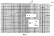
- Fig. 8 illustrates a more detailed example of a local grid refinement 400 as applied to a fracture 402.
- the LGR 400 includes geometrically-spaced fine grid blocks that vary in size from each other by a constant variable. Specifically, in the example of Fig. 8 , the ratio (fx) of the size of any fine grid block (dx i-1 ) to an adjacent grid block closer to the fracture 402 (dx i ) is 1.1. In other embodiments, however, the geometric factor may be in a range of about 1.05 to 1.3, or, may be a different value depending upon the characteristics of the reservoir.
- This geometric grid block arrangement increases the accuracy and computational efficiency of reservoir simulation because regions increasingly closer to a structure of interest are increasingly scrutinized. Thus, when a reservoir modeled with geometric LGRs is simulated, computing power is biased toward areas of the model in which more pressure movement is expected (i.e., regions near a fracture).
- a drilling plan may be implemented based on the modeling.
- the formation evaluated with the foregoing method may have hundreds of fractures or other structures that must be taken into consideration when determining the expected flow of a reservoir over a period of time.
- the plan includes preparing equipment to construct a wellbore, identifying one or more wellbores to be drilled in a formation and drilling of a wellbore into a reservoir based on desired or modeled flow.
- the number, location and trajectory of wellbores in a formation relative to the fractures can be determined using the method of the invention in order to achieve a particular flow over a period of time.
- a drilling plan may be implemented and data from the drilling process may be used to update the model.
- porosity and permeability can be determined during the process of drilling a wellbore. This real-time data may be used to adjust the wellbore being drilled or alter the number, location and trajectory of planned wellbores.
- the system of the invention may be utilized during the drilling process on the fly or iteratively to calculate and re-calculate anticipated reservoir flow over a period of time as parameters change or are clarified or adjusted. In either case, the results of the dynamic calculations may be utilized to alter a previously implemented drilling plan.
- the present disclosure is directed to a computer-implemented method of modeling a formation.
- the method includes applying a coarse grid to a geologic formation of interest, the coarse grid having a plurality of coarse grid blocks and identifying a structure of interest disposed in the formation. Further, the method includes determining a fine grid zone around the structure based upon a time period for flow simulation of the geologic formation and a geologic characteristic of the geologic formation in a local region adjacent the structure and applying a fine grid to the coarse grid blocks encompassed by the fine grid zone.
- the present disclosure is directed to a computer-implemented reservoir simulation system.
- the system includes a processor, a non-transitory, computer-readable storage medium accessible by the processor, and software instructions stored on the storage medium.
- the instructions are executable by the processor for applying a coarse grid to a reservoir, the coarse grid having a plurality of coarse grid blocks identifying a fracture of interest disposed in the reservoir, determining an average geologic characteristic for a local region adjacent the fracture, and determining a fine grid zone around the fracture based upon a time period for flow simulation of the reservoir and the geologic characteristic.
- the determining includes calculating a distance X val away from the fracture at which the fine grid zone terminates based upon the time period for simulation and the geologic characteristic and defining the fine grid zone by the coarse grid blocks within the distance X val away from the structure in a direction. Further, the instructions are executable for applying a local grid refinement ("LGR") to the coarse grid blocks encompassed by the fine grid zone.
- LGR local grid refinement
- the present disclosure is directed to a computer-implemented reservoir simulation system.
- the system includes a processor, a non-transitory storage medium accessible by the processor, and software instructions stored on the storage medium.
- the instructions are executable by the processor for applying a coarse grid to a reservoir, the coarse grid having a plurality of coarse grid blocks and identifying a fracture of interest disposed in the reservoir.
- the instructions are also executable by the processor for determining a fine grid zone around the fracture based upon a time period for simulation of the reservoir, porosity of a region adjacent the fracture and permeability of the region adjacent the fracture and applying a fine grid to the coarse grid blocks encompassed by the fine grid zone.
- the present disclosure is directed to a method for drilling a wellbore in reservoir.
- the method includes applying a coarse grid to a geologic formation of interest, the coarse grid having a plurality of coarse grid blocks, identifying a structure of interest disposed in the formation, and determining a fine grid zone around the structure based upon a time period for flow simulation of the geologic formation and a geologic characteristic of the geologic formation in a local region adjacent the structure.
- the method also includes applying a fine grid to the coarse grid blocks encompassed by the fine grid zone to determine flow adjacent the structure, selecting a position and trajectory for a wellbore in the formation based on the determined flow.
- the method includes preparing equipment to construct a portion of said wellbore and drilling a wellbore in accordance with the selected trajectory.
Landscapes
- Engineering & Computer Science (AREA)
- Physics & Mathematics (AREA)
- Life Sciences & Earth Sciences (AREA)
- Remote Sensing (AREA)
- General Physics & Mathematics (AREA)
- General Life Sciences & Earth Sciences (AREA)
- Geophysics (AREA)
- Geology (AREA)
- Acoustics & Sound (AREA)
- Environmental & Geological Engineering (AREA)
- Theoretical Computer Science (AREA)
- Geometry (AREA)
- Computer Hardware Design (AREA)
- Evolutionary Computation (AREA)
- General Engineering & Computer Science (AREA)
- Chemical & Material Sciences (AREA)
- Chemical Kinetics & Catalysis (AREA)
- Mathematical Analysis (AREA)
- Computing Systems (AREA)
- Fluid Mechanics (AREA)
- Algebra (AREA)
- Mathematical Optimization (AREA)
- Mathematical Physics (AREA)
- Pure & Applied Mathematics (AREA)
- Management, Administration, Business Operations System, And Electronic Commerce (AREA)
- Porous Artificial Stone Or Porous Ceramic Products (AREA)
- Aiming, Guidance, Guns With A Light Source, Armor, Camouflage, And Targets (AREA)
- Silicon Compounds (AREA)
- Investigating Strength Of Materials By Application Of Mechanical Stress (AREA)
- Geophysics And Detection Of Objects (AREA)
Claims (15)
- Procédé mis en œuvre par ordinateur de modélisation d'une formation, comprenant :l'application par un processeur d'une grille grossière (308) à une formation géologique d'intérêt (300), la grille grossière ayant une pluralité de blocs de grille grossière (310) ;l'identification d'une structure d'intérêt (304) disposée dans la formation ;la détermination d'une zone de grille fine (320) autour de la structure sur la base d'une période pour la simulation d'écoulement de la formation géologique et d'une caractéristique géologique de la formation géologique dans une région locale adjacente à la structure ; etl'application d'une grille fine (324) aux blocs de grille grossière englobés par la zone de grille fine,dans lequel la détermination de la zone de grille fine comporte le calcul d'une distance (322) Xval par rapport à la structure au niveau de laquelle la zone de grille fine se termine, le calcul étant basé sur la période pour la simulation d'écoulement et la caractéristique géologique, le procédé étant caractérisé en ce que :une perméabilité moyenne et une porosité moyenne de la région locale adjacente à la structure sont déterminées, etle calcul de la distance Xval est réalisé selon

où temps = la période pour la simulation, k = la perméabilité moyenne pour la région locale adjacente à la structure, por = la porosité moyenne de la région locale adjacente à la structure, et a = une constante empirique déterminée par simulation d'étalonnage d'un sous-ensemble linéaire de la formation. - Procédé mis en œuvre par ordinateur selon la revendication 1, dans lequel la zone de grille fine est définie par les blocs de grille grossière situés à la distance Xval de la structure dans n'importe quelle direction.
- Procédé mis en œuvre par ordinateur selon la revendication 1 ou 2, dans lequel la zone de grille fine est définie par les blocs de grille grossière situés à la distance Xval de la structure dans une direction.
- Procédé mis en œuvre par ordinateur selon la revendication 3, dans lequel la zone de grille fine comporte tous les blocs de grille grossière ayant un point central inférieur à la distance Xval dans la direction opposée à la structure.
- Procédé mis en œuvre par ordinateur selon l'une quelconque des revendications 1 à 4, comportant en outre la définition de la région locale adjacente à la structure sur la base de la distance entre la structure et les structures adjacentes dans la formation.
- Procédé mis en œuvre par ordinateur selon la revendication 5, dans lequel la région locale est définie par des blocs de grille grossière situés à une distance approximativement égale à une distance à mi-chemin entre la structure et une structure adjacente.
- Procédé mis en œuvre par ordinateur selon la revendication 6, dans lequel la caractéristique géologique de la formation dans la région locale adjacente à la structure est définie comme étant la caractéristique géologique moyenne des blocs de grille grossière englobés par la région locale.
- Procédé mis en œuvre par ordinateur selon l'une quelconque des revendications 1 à 7, dans lequel la caractéristique géologique est au moins l'une parmi la perméabilité et la porosité.
- Procédé mis en œuvre par ordinateur selon l'une quelconque des revendications 1 à 8, dans lequel l'application de la grille fine comporte l'application d'un raffinement de grille local ayant des blocs de grille fine géométriquement espacés des blocs de grille grossière englobés par la zone de grille fine.
- Procédé mis en œuvre par ordinateur selon l'une quelconque des revendications 1 à 9, dans lequel la structure est une fracture et la formation est un réservoir.
- Procédé mis en œuvre par ordinateur selon la revendication 10, dans lequel la formation est un réservoir de gaz de schiste à perméabilité extrêmement faible.
- Système de simulation de réservoir mis en œuvre par ordinateur, le système comprenant :un processeur (102) ;un support de stockage (104) non transitoire, lisible par ordinateur, accessible par le processeur ; etdes instructions logicielles (110) stockées sur le support de stockage qui, lorsqu'elles sont exécutées par le processeur, sont configurées pour exécuter le procédé mis en œuvre par ordinateur selon une quelconque revendication précédente.
- Système de simulation de réservoir mis en œuvre par ordinateur selon la revendication 12,
dans lequel la caractéristique géologique est au moins l'une parmi la perméabilité et la porosité, ou
dans lequel la détermination de la caractéristique géologique moyenne pour la région locale comporte :la définition de la région locale en sélectionnant des blocs de grille grossière situés à une distance approximativement à mi-chemin entre la fracture et une fracture adjacente ; etle calcul de la moyenne de la caractéristique géologique de chaque bloc de grille grossière englobé par la région locale. - Procédé de forage d'un puits de forage dans un réservoir, le procédé comprenant :l'application du procédé selon la revendication 1 à une formation géologique d'intérêt, ayant une structure d'intérêt disposée dans la formation pour déterminer un écoulement adjacent à la structure ;sur la base de l'écoulement déterminé, la sélection d'une position et d'une trajectoire pour un puits de forage dans la formation ;la préparation d'un équipement pour construire une partie dudit puits de forage ; etle forage d'un puits de forage selon la trajectoire choisie.
- Procédé selon la revendication 14, dans lequel la zone de grille fine est définie par les blocs de grille grossière situés à la distance Xval de la structure dans une direction.
Applications Claiming Priority (1)
| Application Number | Priority Date | Filing Date | Title |
|---|---|---|---|
| PCT/US2012/031626 WO2013147875A2 (fr) | 2012-03-30 | 2012-03-30 | Système et procédé pour le raffinement de réseau local automatique dans des systèmes de simulation de réservoir |
Publications (3)
| Publication Number | Publication Date |
|---|---|
| EP2831804A2 EP2831804A2 (fr) | 2015-02-04 |
| EP2831804A4 EP2831804A4 (fr) | 2017-01-18 |
| EP2831804B1 true EP2831804B1 (fr) | 2019-12-25 |
Family
ID=49261377
Family Applications (1)
| Application Number | Title | Priority Date | Filing Date |
|---|---|---|---|
| EP12873117.1A Active EP2831804B1 (fr) | 2012-03-30 | 2012-03-30 | Système et procédé pour le raffinement de réseau local automatique dans des systèmes de simulation de réservoir |
Country Status (7)
| Country | Link |
|---|---|
| US (1) | US9753181B2 (fr) |
| EP (1) | EP2831804B1 (fr) |
| AR (1) | AR090463A1 (fr) |
| AU (1) | AU2012375233B2 (fr) |
| CA (1) | CA2868756C (fr) |
| RU (1) | RU2582482C1 (fr) |
| WO (1) | WO2013147875A2 (fr) |
Families Citing this family (13)
| Publication number | Priority date | Publication date | Assignee | Title |
|---|---|---|---|---|
| EP2831804B1 (fr) | 2012-03-30 | 2019-12-25 | Landmark Graphics Corporation | Système et procédé pour le raffinement de réseau local automatique dans des systèmes de simulation de réservoir |
| US10310139B2 (en) * | 2014-07-11 | 2019-06-04 | Landmark Graphics Corporation | Anisotropic geometry-adaptive refinement for reservoir mesh creation |
| EP3086229A1 (fr) * | 2015-04-20 | 2016-10-26 | Repsol, S.A. | Gestion de production d'énergie à l'aide d'hydrocarbures tout en maintenant de manière proactive une charge de travail équilibrée |
| GB2556572A (en) | 2015-09-04 | 2018-05-30 | Halliburton Energy Services Inc | Time-to-finish simulation forecaster |
| US20180372910A1 (en) * | 2016-03-01 | 2018-12-27 | Halliburton Energy Services, Inc. | Method for flexible structured gridding using nested locally refined grids |
| CN108229048B (zh) * | 2018-01-17 | 2021-04-06 | 陕西延长石油(集团)有限责任公司研究院 | 一种考虑页岩基质差异的多场耦合渗透率计算方法 |
| US10983233B2 (en) | 2019-03-12 | 2021-04-20 | Saudi Arabian Oil Company | Method for dynamic calibration and simultaneous closed-loop inversion of simulation models of fractured reservoirs |
| GB2596943A (en) * | 2019-04-25 | 2022-01-12 | Landmark Graphics Corp | Systems and methods for determining grid cell count for reservoir simulation |
| US11009623B2 (en) * | 2019-07-16 | 2021-05-18 | Saudi Arabian Oil Company | Calculating shut-in bottom-hole pressure in numerical reservoir simulations |
| US11754745B2 (en) | 2020-06-30 | 2023-09-12 | Saudi Arabian Oil Company | Methods and systems for flow-based coarsening of reservoir grid models |
| RU2020125337A (ru) * | 2020-07-30 | 2022-01-31 | Общество с ограниченной ответственностью «Газпромнефть Научно-Технический Центр» | Способ и система моделирования динамики нефтегазовых пластов |
| US12189072B2 (en) | 2020-10-05 | 2025-01-07 | Saudi Arabian Oil Company | System and method to identify high-impact discrete fracture model realizations for accelerated calibration of reservoir simulation models |
| US20230259670A1 (en) * | 2022-02-16 | 2023-08-17 | Saudi Arabian Oil Comoany | Permeability modeling in a reservoir simulation model using dynamic pressure transient analysis |
Family Cites Families (17)
| Publication number | Priority date | Publication date | Assignee | Title |
|---|---|---|---|---|
| US6018497A (en) * | 1997-02-27 | 2000-01-25 | Geoquest | Method and apparatus for generating more accurate earth formation grid cell property information for use by a simulator to display more accurate simulation results of the formation near a wellbore |
| US6106561A (en) * | 1997-06-23 | 2000-08-22 | Schlumberger Technology Corporation | Simulation gridding method and apparatus including a structured areal gridder adapted for use by a reservoir simulator |
| US6826520B1 (en) * | 1999-06-24 | 2004-11-30 | Exxonmobil Upstream Research Company | Method of upscaling permeability for unstructured grids |
| US7716029B2 (en) * | 2006-05-15 | 2010-05-11 | Schlumberger Technology Corporation | Method for optimal gridding in reservoir simulation |
| WO2007149766A2 (fr) | 2006-06-18 | 2007-12-27 | Chevron U.S.A. Inc. | procédé, appareil et système pour une simulation de réservoir utilisant un procédé de volume fini à échelles multiples comprenant une modélisation d'huile noire |
| WO2009056992A2 (fr) * | 2007-11-01 | 2009-05-07 | Schlumberger Canada Limited | Simulation de fracture de réservoir |
| EA201170472A1 (ru) * | 2008-09-19 | 2011-10-31 | Шеврон Ю.Эс.Эй. Инк. | Реализованные посредством компьютера системы и способы для использования при моделировании геомеханической системы коллектора |
| US10087721B2 (en) | 2010-07-29 | 2018-10-02 | Exxonmobil Upstream Research Company | Methods and systems for machine—learning based simulation of flow |
| CA2805446C (fr) * | 2010-07-29 | 2016-08-16 | Exxonmobil Upstream Research Company | Procedes et systemes de simulation d'ecoulement basee sur un apprentissage machine |
| EP2742403A4 (fr) * | 2011-09-16 | 2015-07-15 | Landmark Graphics Corp | Procédés et systèmes de commande d'applications pétrotechniques par le geste |
| US9262563B2 (en) * | 2011-10-26 | 2016-02-16 | Landmark Graphics Corporation | Methods and systems of modeling hydrocarbon flow from kerogens in a hydrocarbon bearing formation |
| BR112014010082A8 (pt) * | 2011-10-28 | 2017-06-20 | Landmark Graphics Corp | método, sistema de computador e meio não transitório lido por computador armazenando um programa |
| EP2831804B1 (fr) | 2012-03-30 | 2019-12-25 | Landmark Graphics Corporation | Système et procédé pour le raffinement de réseau local automatique dans des systèmes de simulation de réservoir |
| AU2012377414B2 (en) * | 2012-04-18 | 2015-10-29 | Landmark Graphics Corporation | Methods and systems of modeling hydrocarbon flow from layered shale formations |
| EP2845142A4 (fr) * | 2012-04-30 | 2016-04-20 | Landmark Graphics Corp | Système et procédé de simulation de réservoir au moyen de données à la demande |
| EP2912494A4 (fr) * | 2012-10-24 | 2016-06-01 | Landmark Graphics Corp | Procédé et système de détermination de caractéristiques d'une formation |
| SG11201601551YA (en) * | 2013-10-01 | 2016-03-30 | Landmark Graphics Corp | In-situ wellbore, core and cuttings information system |
-
2012
- 2012-03-30 EP EP12873117.1A patent/EP2831804B1/fr active Active
- 2012-03-30 WO PCT/US2012/031626 patent/WO2013147875A2/fr not_active Ceased
- 2012-03-30 US US14/389,685 patent/US9753181B2/en not_active Expired - Fee Related
- 2012-03-30 RU RU2014140790/28A patent/RU2582482C1/ru not_active IP Right Cessation
- 2012-03-30 AU AU2012375233A patent/AU2012375233B2/en not_active Ceased
- 2012-03-30 CA CA2868756A patent/CA2868756C/fr not_active Expired - Fee Related
-
2013
- 2013-03-21 AR ARP130100932A patent/AR090463A1/es unknown
Non-Patent Citations (1)
| Title |
|---|
| None * |
Also Published As
| Publication number | Publication date |
|---|---|
| AR090463A1 (es) | 2014-11-12 |
| US9753181B2 (en) | 2017-09-05 |
| AU2012375233B2 (en) | 2015-12-03 |
| CA2868756A1 (fr) | 2013-10-03 |
| RU2582482C1 (ru) | 2016-04-27 |
| WO2013147875A2 (fr) | 2013-10-03 |
| WO2013147875A3 (fr) | 2014-05-01 |
| CA2868756C (fr) | 2018-01-16 |
| AU2012375233A1 (en) | 2014-09-25 |
| EP2831804A4 (fr) | 2017-01-18 |
| US20150058262A1 (en) | 2015-02-26 |
| EP2831804A2 (fr) | 2015-02-04 |
Similar Documents
| Publication | Publication Date | Title |
|---|---|---|
| EP2831804B1 (fr) | Système et procédé pour le raffinement de réseau local automatique dans des systèmes de simulation de réservoir | |
| Chai et al. | An efficient method for fractured shale reservoir history matching: The embedded discrete fracture multi-continuum approach | |
| EP3018502A2 (fr) | Modélisation des fractures conductrices de fluides dans une grille de simulation de réservoir | |
| Ping et al. | History matching of fracture distributions by ensemble Kalman filter combined with vector based level set parameterization | |
| Yunsheng et al. | A smart productivity evaluation method for shale gas wells based on 3D fractal fracture network model | |
| CN106407503B (zh) | 储层裂缝预测方法及装置 | |
| CN103348265B (zh) | 更新地质单元模型的方法和系统 | |
| Lee et al. | Improvement of ensemble smoother with clustered covariance for channelized reservoirs | |
| CN108603402A (zh) | 对矿物质沉淀和溶解造成的多孔介质中毛细管压力和相对渗透率的变化进行建模和预测 | |
| Lei et al. | Numerical modeling of exploitation and reinjection of the Guantao geothermal reservoir in Tanggu District, Tianjin, China | |
| US20120035896A1 (en) | Reservoir upscaling method with preserved transmissibility | |
| CN105114063A (zh) | 一种斜井双侧向测井曲线校正方法 | |
| EP2856387B1 (fr) | Système et procédé d'optimisation de simulation de réservoir | |
| KR101647921B1 (ko) | 유·가스 저류층의 실제 가스 생산량에 유사한 저류층 모델을 선정하는 방법 및 이를 이용한 생산량 예측 방법 | |
| CN111677486A (zh) | 致密油二氧化碳吞吐模拟方法、装置及存储介质 | |
| CN110489928A (zh) | 浅埋煤层矿区导水裂隙带发育高度预计方法及系统 | |
| Ping et al. | Data assimilation method for fractured reservoirs using mimetic finite differences and ensemble Kalman filter | |
| WO2017151100A1 (fr) | Représentation géo-cellulaire 3d hybride de sous-ensembles sélectionnés de réseaux de fractures naturelles | |
| AlQassab et al. | Estimating the size and orientation of hydraulic fractures using microseismic events | |
| Fradkin et al. | On identification and validation of some geothermal models | |
| Nakashima et al. | Accurate representation of near-well effects in coarse-scale models of primary oil production | |
| CN107783204A (zh) | 储层裂缝预测方法及系统 | |
| CN104715298A (zh) | 一种基于灰色系统理论的提高采收率潜力预测方法 | |
| US20150198737A1 (en) | Automatic cartesian gridding with logarithmic refinement at arbitrary locations | |
| CN105649610A (zh) | 一种获取油藏压力的方法及装置 |
Legal Events
| Date | Code | Title | Description |
|---|---|---|---|
| PUAI | Public reference made under article 153(3) epc to a published international application that has entered the european phase |
Free format text: ORIGINAL CODE: 0009012 |
|
| 17P | Request for examination filed |
Effective date: 20140916 |
|
| AK | Designated contracting states |
Kind code of ref document: A2 Designated state(s): AL AT BE BG CH CY CZ DE DK EE ES FI FR GB GR HR HU IE IS IT LI LT LU LV MC MK MT NL NO PL PT RO RS SE SI SK SM TR |
|
| AX | Request for extension of the european patent |
Extension state: BA ME |
|
| RIN1 | Information on inventor provided before grant (corrected) |
Inventor name: GORELL, SHELDON Inventor name: KUMAR, AMIT |
|
| DAX | Request for extension of the european patent (deleted) | ||
| A4 | Supplementary search report drawn up and despatched |
Effective date: 20161219 |
|
| RIC1 | Information provided on ipc code assigned before grant |
Ipc: G01V 9/00 20060101ALI20161213BHEP Ipc: G01V 1/30 20060101ALI20161213BHEP Ipc: G06G 7/48 20060101AFI20161213BHEP Ipc: G06F 17/50 20060101ALI20161213BHEP Ipc: G01V 99/00 20090101ALI20161213BHEP |
|
| REG | Reference to a national code |
Ref country code: DE Ref legal event code: R079 Ref document number: 602012066789 Country of ref document: DE Free format text: PREVIOUS MAIN CLASS: G06G0007480000 Ipc: G01V0001300000 |
|
| GRAP | Despatch of communication of intention to grant a patent |
Free format text: ORIGINAL CODE: EPIDOSNIGR1 |
|
| STAA | Information on the status of an ep patent application or granted ep patent |
Free format text: STATUS: GRANT OF PATENT IS INTENDED |
|
| RIC1 | Information provided on ipc code assigned before grant |
Ipc: G01V 99/00 20090101ALI20190613BHEP Ipc: G01V 1/30 20060101AFI20190613BHEP Ipc: G06F 17/50 20060101ALI20190613BHEP |
|
| INTG | Intention to grant announced |
Effective date: 20190708 |
|
| GRAS | Grant fee paid |
Free format text: ORIGINAL CODE: EPIDOSNIGR3 |
|
| GRAA | (expected) grant |
Free format text: ORIGINAL CODE: 0009210 |
|
| STAA | Information on the status of an ep patent application or granted ep patent |
Free format text: STATUS: THE PATENT HAS BEEN GRANTED |
|
| AK | Designated contracting states |
Kind code of ref document: B1 Designated state(s): AL AT BE BG CH CY CZ DE DK EE ES FI FR GB GR HR HU IE IS IT LI LT LU LV MC MK MT NL NO PL PT RO RS SE SI SK SM TR |
|
| REG | Reference to a national code |
Ref country code: GB Ref legal event code: FG4D |
|
| REG | Reference to a national code |
Ref country code: CH Ref legal event code: EP |
|
| REG | Reference to a national code |
Ref country code: AT Ref legal event code: REF Ref document number: 1217742 Country of ref document: AT Kind code of ref document: T Effective date: 20200115 |
|
| REG | Reference to a national code |
Ref country code: DE Ref legal event code: R096 Ref document number: 602012066789 Country of ref document: DE |
|
| REG | Reference to a national code |
Ref country code: IE Ref legal event code: FG4D |
|
| REG | Reference to a national code |
Ref country code: NO Ref legal event code: T2 Effective date: 20191225 |
|
| REG | Reference to a national code |
Ref country code: NL Ref legal event code: MP Effective date: 20191225 |
|
| PG25 | Lapsed in a contracting state [announced via postgrant information from national office to epo] |
Ref country code: LT Free format text: LAPSE BECAUSE OF FAILURE TO SUBMIT A TRANSLATION OF THE DESCRIPTION OR TO PAY THE FEE WITHIN THE PRESCRIBED TIME-LIMIT Effective date: 20191225 Ref country code: GR Free format text: LAPSE BECAUSE OF FAILURE TO SUBMIT A TRANSLATION OF THE DESCRIPTION OR TO PAY THE FEE WITHIN THE PRESCRIBED TIME-LIMIT Effective date: 20200326 Ref country code: FI Free format text: LAPSE BECAUSE OF FAILURE TO SUBMIT A TRANSLATION OF THE DESCRIPTION OR TO PAY THE FEE WITHIN THE PRESCRIBED TIME-LIMIT Effective date: 20191225 Ref country code: BG Free format text: LAPSE BECAUSE OF FAILURE TO SUBMIT A TRANSLATION OF THE DESCRIPTION OR TO PAY THE FEE WITHIN THE PRESCRIBED TIME-LIMIT Effective date: 20200325 Ref country code: SE Free format text: LAPSE BECAUSE OF FAILURE TO SUBMIT A TRANSLATION OF THE DESCRIPTION OR TO PAY THE FEE WITHIN THE PRESCRIBED TIME-LIMIT Effective date: 20191225 Ref country code: LV Free format text: LAPSE BECAUSE OF FAILURE TO SUBMIT A TRANSLATION OF THE DESCRIPTION OR TO PAY THE FEE WITHIN THE PRESCRIBED TIME-LIMIT Effective date: 20191225 |
|
| PGFP | Annual fee paid to national office [announced via postgrant information from national office to epo] |
Ref country code: GB Payment date: 20200107 Year of fee payment: 9 Ref country code: NO Payment date: 20200327 Year of fee payment: 9 |
|
| REG | Reference to a national code |
Ref country code: LT Ref legal event code: MG4D |
|
| PG25 | Lapsed in a contracting state [announced via postgrant information from national office to epo] |
Ref country code: HR Free format text: LAPSE BECAUSE OF FAILURE TO SUBMIT A TRANSLATION OF THE DESCRIPTION OR TO PAY THE FEE WITHIN THE PRESCRIBED TIME-LIMIT Effective date: 20191225 Ref country code: RS Free format text: LAPSE BECAUSE OF FAILURE TO SUBMIT A TRANSLATION OF THE DESCRIPTION OR TO PAY THE FEE WITHIN THE PRESCRIBED TIME-LIMIT Effective date: 20191225 |
|
| PG25 | Lapsed in a contracting state [announced via postgrant information from national office to epo] |
Ref country code: AL Free format text: LAPSE BECAUSE OF FAILURE TO SUBMIT A TRANSLATION OF THE DESCRIPTION OR TO PAY THE FEE WITHIN THE PRESCRIBED TIME-LIMIT Effective date: 20191225 |
|
| PG25 | Lapsed in a contracting state [announced via postgrant information from national office to epo] |
Ref country code: PT Free format text: LAPSE BECAUSE OF FAILURE TO SUBMIT A TRANSLATION OF THE DESCRIPTION OR TO PAY THE FEE WITHIN THE PRESCRIBED TIME-LIMIT Effective date: 20200520 Ref country code: CZ Free format text: LAPSE BECAUSE OF FAILURE TO SUBMIT A TRANSLATION OF THE DESCRIPTION OR TO PAY THE FEE WITHIN THE PRESCRIBED TIME-LIMIT Effective date: 20191225 Ref country code: RO Free format text: LAPSE BECAUSE OF FAILURE TO SUBMIT A TRANSLATION OF THE DESCRIPTION OR TO PAY THE FEE WITHIN THE PRESCRIBED TIME-LIMIT Effective date: 20191225 Ref country code: EE Free format text: LAPSE BECAUSE OF FAILURE TO SUBMIT A TRANSLATION OF THE DESCRIPTION OR TO PAY THE FEE WITHIN THE PRESCRIBED TIME-LIMIT Effective date: 20191225 Ref country code: NL Free format text: LAPSE BECAUSE OF FAILURE TO SUBMIT A TRANSLATION OF THE DESCRIPTION OR TO PAY THE FEE WITHIN THE PRESCRIBED TIME-LIMIT Effective date: 20191225 |
|
| PG25 | Lapsed in a contracting state [announced via postgrant information from national office to epo] |
Ref country code: SM Free format text: LAPSE BECAUSE OF FAILURE TO SUBMIT A TRANSLATION OF THE DESCRIPTION OR TO PAY THE FEE WITHIN THE PRESCRIBED TIME-LIMIT Effective date: 20191225 Ref country code: SK Free format text: LAPSE BECAUSE OF FAILURE TO SUBMIT A TRANSLATION OF THE DESCRIPTION OR TO PAY THE FEE WITHIN THE PRESCRIBED TIME-LIMIT Effective date: 20191225 Ref country code: IS Free format text: LAPSE BECAUSE OF FAILURE TO SUBMIT A TRANSLATION OF THE DESCRIPTION OR TO PAY THE FEE WITHIN THE PRESCRIBED TIME-LIMIT Effective date: 20200425 |
|
| REG | Reference to a national code |
Ref country code: DE Ref legal event code: R097 Ref document number: 602012066789 Country of ref document: DE |
|
| REG | Reference to a national code |
Ref country code: DE Ref legal event code: R119 Ref document number: 602012066789 Country of ref document: DE |
|
| PG25 | Lapsed in a contracting state [announced via postgrant information from national office to epo] |
Ref country code: DK Free format text: LAPSE BECAUSE OF FAILURE TO SUBMIT A TRANSLATION OF THE DESCRIPTION OR TO PAY THE FEE WITHIN THE PRESCRIBED TIME-LIMIT Effective date: 20191225 Ref country code: MC Free format text: LAPSE BECAUSE OF FAILURE TO SUBMIT A TRANSLATION OF THE DESCRIPTION OR TO PAY THE FEE WITHIN THE PRESCRIBED TIME-LIMIT Effective date: 20191225 Ref country code: ES Free format text: LAPSE BECAUSE OF FAILURE TO SUBMIT A TRANSLATION OF THE DESCRIPTION OR TO PAY THE FEE WITHIN THE PRESCRIBED TIME-LIMIT Effective date: 20191225 |
|
| PLBE | No opposition filed within time limit |
Free format text: ORIGINAL CODE: 0009261 |
|
| REG | Reference to a national code |
Ref country code: CH Ref legal event code: PL |
|
| STAA | Information on the status of an ep patent application or granted ep patent |
Free format text: STATUS: NO OPPOSITION FILED WITHIN TIME LIMIT |
|
| REG | Reference to a national code |
Ref country code: AT Ref legal event code: MK05 Ref document number: 1217742 Country of ref document: AT Kind code of ref document: T Effective date: 20191225 |
|
| PG25 | Lapsed in a contracting state [announced via postgrant information from national office to epo] |
Ref country code: SI Free format text: LAPSE BECAUSE OF FAILURE TO SUBMIT A TRANSLATION OF THE DESCRIPTION OR TO PAY THE FEE WITHIN THE PRESCRIBED TIME-LIMIT Effective date: 20191225 |
|
| 26N | No opposition filed |
Effective date: 20200928 |
|
| REG | Reference to a national code |
Ref country code: BE Ref legal event code: MM Effective date: 20200331 |
|
| PG25 | Lapsed in a contracting state [announced via postgrant information from national office to epo] |
Ref country code: LU Free format text: LAPSE BECAUSE OF NON-PAYMENT OF DUE FEES Effective date: 20200330 |
|
| PG25 | Lapsed in a contracting state [announced via postgrant information from national office to epo] |
Ref country code: FR Free format text: LAPSE BECAUSE OF NON-PAYMENT OF DUE FEES Effective date: 20200331 Ref country code: IT Free format text: LAPSE BECAUSE OF FAILURE TO SUBMIT A TRANSLATION OF THE DESCRIPTION OR TO PAY THE FEE WITHIN THE PRESCRIBED TIME-LIMIT Effective date: 20191225 Ref country code: DE Free format text: LAPSE BECAUSE OF NON-PAYMENT OF DUE FEES Effective date: 20201001 Ref country code: CH Free format text: LAPSE BECAUSE OF NON-PAYMENT OF DUE FEES Effective date: 20200331 Ref country code: LI Free format text: LAPSE BECAUSE OF NON-PAYMENT OF DUE FEES Effective date: 20200331 Ref country code: AT Free format text: LAPSE BECAUSE OF FAILURE TO SUBMIT A TRANSLATION OF THE DESCRIPTION OR TO PAY THE FEE WITHIN THE PRESCRIBED TIME-LIMIT Effective date: 20191225 Ref country code: IE Free format text: LAPSE BECAUSE OF NON-PAYMENT OF DUE FEES Effective date: 20200330 |
|
| PG25 | Lapsed in a contracting state [announced via postgrant information from national office to epo] |
Ref country code: PL Free format text: LAPSE BECAUSE OF FAILURE TO SUBMIT A TRANSLATION OF THE DESCRIPTION OR TO PAY THE FEE WITHIN THE PRESCRIBED TIME-LIMIT Effective date: 20191225 Ref country code: BE Free format text: LAPSE BECAUSE OF NON-PAYMENT OF DUE FEES Effective date: 20200331 |
|
| REG | Reference to a national code |
Ref country code: NO Ref legal event code: MMEP |
|
| GBPC | Gb: european patent ceased through non-payment of renewal fee |
Effective date: 20210330 |
|
| PG25 | Lapsed in a contracting state [announced via postgrant information from national office to epo] |
Ref country code: NO Free format text: LAPSE BECAUSE OF NON-PAYMENT OF DUE FEES Effective date: 20210331 Ref country code: GB Free format text: LAPSE BECAUSE OF NON-PAYMENT OF DUE FEES Effective date: 20210330 |
|
| PG25 | Lapsed in a contracting state [announced via postgrant information from national office to epo] |
Ref country code: TR Free format text: LAPSE BECAUSE OF FAILURE TO SUBMIT A TRANSLATION OF THE DESCRIPTION OR TO PAY THE FEE WITHIN THE PRESCRIBED TIME-LIMIT Effective date: 20191225 Ref country code: MT Free format text: LAPSE BECAUSE OF FAILURE TO SUBMIT A TRANSLATION OF THE DESCRIPTION OR TO PAY THE FEE WITHIN THE PRESCRIBED TIME-LIMIT Effective date: 20191225 Ref country code: CY Free format text: LAPSE BECAUSE OF FAILURE TO SUBMIT A TRANSLATION OF THE DESCRIPTION OR TO PAY THE FEE WITHIN THE PRESCRIBED TIME-LIMIT Effective date: 20191225 |
|
| PG25 | Lapsed in a contracting state [announced via postgrant information from national office to epo] |
Ref country code: MK Free format text: LAPSE BECAUSE OF FAILURE TO SUBMIT A TRANSLATION OF THE DESCRIPTION OR TO PAY THE FEE WITHIN THE PRESCRIBED TIME-LIMIT Effective date: 20191225 |