EP2831874B1 - Codage/décodage de transformée de signaux audio harmoniques - Google Patents
Codage/décodage de transformée de signaux audio harmoniques Download PDFInfo
- Publication number
- EP2831874B1 EP2831874B1 EP12790692.3A EP12790692A EP2831874B1 EP 2831874 B1 EP2831874 B1 EP 2831874B1 EP 12790692 A EP12790692 A EP 12790692A EP 2831874 B1 EP2831874 B1 EP 2831874B1
- Authority
- EP
- European Patent Office
- Prior art keywords
- peak
- encoding
- coefficients
- energy
- gain
- Prior art date
- Legal status (The legal status is an assumption and is not a legal conclusion. Google has not performed a legal analysis and makes no representation as to the accuracy of the status listed.)
- Active
Links
Images



Classifications
-
- G—PHYSICS
- G10—MUSICAL INSTRUMENTS; ACOUSTICS
- G10L—SPEECH ANALYSIS TECHNIQUES OR SPEECH SYNTHESIS; SPEECH RECOGNITION; SPEECH OR VOICE PROCESSING TECHNIQUES; SPEECH OR AUDIO CODING OR DECODING
- G10L19/00—Speech or audio signals analysis-synthesis techniques for redundancy reduction, e.g. in vocoders; Coding or decoding of speech or audio signals, using source filter models or psychoacoustic analysis
- G10L19/002—Dynamic bit allocation
-
- G—PHYSICS
- G10—MUSICAL INSTRUMENTS; ACOUSTICS
- G10L—SPEECH ANALYSIS TECHNIQUES OR SPEECH SYNTHESIS; SPEECH RECOGNITION; SPEECH OR VOICE PROCESSING TECHNIQUES; SPEECH OR AUDIO CODING OR DECODING
- G10L19/00—Speech or audio signals analysis-synthesis techniques for redundancy reduction, e.g. in vocoders; Coding or decoding of speech or audio signals, using source filter models or psychoacoustic analysis
- G10L19/02—Speech or audio signals analysis-synthesis techniques for redundancy reduction, e.g. in vocoders; Coding or decoding of speech or audio signals, using source filter models or psychoacoustic analysis using spectral analysis, e.g. transform vocoders or subband vocoders
-
- G—PHYSICS
- G10—MUSICAL INSTRUMENTS; ACOUSTICS
- G10L—SPEECH ANALYSIS TECHNIQUES OR SPEECH SYNTHESIS; SPEECH RECOGNITION; SPEECH OR VOICE PROCESSING TECHNIQUES; SPEECH OR AUDIO CODING OR DECODING
- G10L19/00—Speech or audio signals analysis-synthesis techniques for redundancy reduction, e.g. in vocoders; Coding or decoding of speech or audio signals, using source filter models or psychoacoustic analysis
- G10L19/02—Speech or audio signals analysis-synthesis techniques for redundancy reduction, e.g. in vocoders; Coding or decoding of speech or audio signals, using source filter models or psychoacoustic analysis using spectral analysis, e.g. transform vocoders or subband vocoders
- G10L19/0212—Speech or audio signals analysis-synthesis techniques for redundancy reduction, e.g. in vocoders; Coding or decoding of speech or audio signals, using source filter models or psychoacoustic analysis using spectral analysis, e.g. transform vocoders or subband vocoders using orthogonal transformation
-
- G—PHYSICS
- G10—MUSICAL INSTRUMENTS; ACOUSTICS
- G10L—SPEECH ANALYSIS TECHNIQUES OR SPEECH SYNTHESIS; SPEECH RECOGNITION; SPEECH OR VOICE PROCESSING TECHNIQUES; SPEECH OR AUDIO CODING OR DECODING
- G10L19/00—Speech or audio signals analysis-synthesis techniques for redundancy reduction, e.g. in vocoders; Coding or decoding of speech or audio signals, using source filter models or psychoacoustic analysis
- G10L19/02—Speech or audio signals analysis-synthesis techniques for redundancy reduction, e.g. in vocoders; Coding or decoding of speech or audio signals, using source filter models or psychoacoustic analysis using spectral analysis, e.g. transform vocoders or subband vocoders
- G10L19/028—Noise substitution, i.e. substituting non-tonal spectral components by noisy source
-
- G—PHYSICS
- G10—MUSICAL INSTRUMENTS; ACOUSTICS
- G10L—SPEECH ANALYSIS TECHNIQUES OR SPEECH SYNTHESIS; SPEECH RECOGNITION; SPEECH OR VOICE PROCESSING TECHNIQUES; SPEECH OR AUDIO CODING OR DECODING
- G10L19/00—Speech or audio signals analysis-synthesis techniques for redundancy reduction, e.g. in vocoders; Coding or decoding of speech or audio signals, using source filter models or psychoacoustic analysis
- G10L19/02—Speech or audio signals analysis-synthesis techniques for redundancy reduction, e.g. in vocoders; Coding or decoding of speech or audio signals, using source filter models or psychoacoustic analysis using spectral analysis, e.g. transform vocoders or subband vocoders
- G10L19/032—Quantisation or dequantisation of spectral components
- G10L19/038—Vector quantisation, e.g. TwinVQ audio
Definitions
- the proposed technology relates to transform encoding/decoding of audio signals, especially harmonic audio signals.
- Transform encoding is the main technology used to compress and transmit audio signals.
- the concept of transform encoding is to first convert a signal to the frequency domain, and then to quantize and transmit the transform coefficients.
- the decoder uses the received transform coefficients to reconstruct the signal waveform by applying the inverse frequency transform, see Fig. 1 .
- an audio signal X ( n ) is forwarded to a frequency transformer 10.
- the resulting frequency transform Y ( k ) is forwarded to a transform encoder 12, and the encoded transform is transmitted to the decoder, where it is decoded by a transform decoder 14.
- the decoded transform ⁇ ( k ) is forwarded to an inverse frequency transformer 16 that transforms it into a decoded audio signal X ⁇ ( n ) .
- the motivation behind this scheme is that frequency domain coefficients can be more efficiently quantized for the following reasons:
- the signal waveform is transformed on a block by block basis (with 50% overlap), using the Modified Discrete Cosine Transform (MDCT).
- MDCT Modified Discrete Cosine Transform
- a block signal waveform X ( n ) is transformed into an MDCT vector Y ( k ).
- Residual sub-vectors or shapes are obtained by scaling the MDCT sub-vectors with the corresponding envelope gains, e.g. the residual in each band is scaled to have unit Root Mean Square (RMS) energy. Then the residual sub-vectors or shapes are quantized with different number of bits based on the corresponding envelope gains. Finally, at the decoder, the MDCT vector is reconstructed by scaling up the residual sub-vectors or shapes with the corresponding envelope gains, and an inverse MDCT is used to reconstruct the time-domain audio frame.
- RMS Root Mean Square
- the conventional transform encoding concept does not work well with very harmonic audio signals, e.g. single instruments.
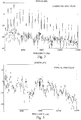
- An example of such a harmonic spectrum is illustrated in Fig. 2 (for comparison a typical audio spectrum without excessive harmonics is shown Fig. 3 ).
- the reason is that the normalization with the spectrum envelope does not result in a sufficiently "flat" residual vector, and the residual encoding scheme cannot produce an audio signal of acceptable quality.
- This mismatch between the signal and the encoding model can be resolved only at very high bitrates, but in most cases this solution is not suitable.
- US 2012/0029923 discloses a scheme for coding a set of transform coefficients that represent an audio frequency range of a signal uses a harmonic model to parameterize a relationship between the locations of regions of significant energy in the frequency domain.
- An object of the proposed technology is a transform encoding/decoding scheme that is more suited for harmonic audio signals.
- the proposed technology involves a method of encoding Modified Discrete Cosine Transform coefficients of a harmonic audio signal.
- the method includes the steps of:
- the proposed technology also involves an encoder for encoding Modified Discrete Cosine Transform coefficients of a harmonic audio signal.
- the encoder includes:
- the proposed technology also involves a user equipment (UE) including such an encoder.
- UE user equipment
- the proposed technology also involves a method of reconstructing Modified Discrete Cosine Transform coefficients of an encoded frequency transformed harmonic audio signal.
- the method includes the steps of:
- the proposed technology also involves a decoder for reconstructing Modified Discrete Cosine Transform coefficients of an encoded frequency transformed harmonic audio signal.
- the decoder includes:
- the proposed technology also involves a user equipment (UE) including such a decoder.
- UE user equipment
- the proposed harmonic audio coding encoding/decoding scheme provides better perceptual quality than the conventional coding schemes for a large class of harmonic audio signals.
- Fig. 2 illustrates a typical spectrum of a harmonic audio signal
- Fig. 3 illustrates a typical spectrum of a non-harmonic audio signal.
- the spectrum of the harmonic signal is formed by strong spectral peaks separated by much weaker frequency bands, while the spectrum of the non-harmonic audio signal is much smoother.
- the proposed technology provides an alternative audio encoding model that handles harmonic audio signals better.
- the main concept is that the frequency transform vector, for example an MDCT vector, is not split into envelope and residual part, but instead spectral peaks are directly extracted and quantized, together with neighboring MDCT bins.
- the signal model used in the conventional encoding ⁇ spectrum envelope + residual ⁇ is replaced with a new model ⁇ spectral peaks + noise-floor ⁇ .
- coefficients outside the peak neighborhoods are still coded, since they have an important perceptual role.
- the noise-floor is estimated, then the spectral peaks are extracted by a peak picking algorithm (the corresponding algorithms are described in more detail in APPENDIX I-II).
- a peak picking algorithm the corresponding algorithms are described in more detail in APPENDIX I-II.
- Each peak and its surrounding 4 neighbors are normalized to unit energy at the peak position, see Fig. 4 . In other words, the entire region is scaled such that the peak has amplitude one.
- the peak position, gain (represents peak amplitude, magnitude) and sign are quantized.
- a Vector Quantizer (VQ) is applied to the MDCT bins surrounding the peak and searches for the index I shape of the codebook vector that provides the best match.
- the peak position, gain and sign, as well as the surrounding shape vectors are quantized and the quantization indices ⁇ I position I gain I sign I shape ⁇ are transmitted to the decoder. In addition to these indices the decoder is also informed of the total number of peaks.
- each peak region includes 4 neighbors that symmetrically surround the peak.
- the total number of LF bands or sets depends on the number of available bits, but there are always enough bits reserved to create at least one set. When more bits are available the first set gets more bits assigned until a threshold for the maximum number of bits per set is reached. If there are more bits available another set is created and bits are assigned to this set until the threshold is reached. This procedure is repeated until all available bits have been spent. This means that the crossover frequency at which this process is stopped will be frame dependent, since the number of peaks will vary from frame to frame. The crossover frequency will be determined by the number of bits that are available for LF encoding once the peak regions have been encoded.
- Quantization of the LF sets can be done with any suitable vector quantization scheme, but typically some type of gain-shape encoding is used. For example, factorial pulse coding may be used for the shape vector, and scalar quantizer may be used for the gain.
- a certain number of bits are always reserved for encoding a noise-floor gain of at least one high-frequency band of coefficients outside the peak regions, and above the upper frequency of the LF bands.
- Preferably two gains are used for this purpose. These gains may be obtained from the noise-floor algorithm described in APPENDIX I.
- factorial pulse coding is used for the encoding the low-frequency bands some LF coefficients may not be encoded. These coefficients can instead be included in the high-frequency band encoding.
- the HF bands are not necessarily made up from consecutive coefficients. For this reason the bands will also be referred to as "sets" below.
- the spectrum envelope for a bandwidth extension (BWE) region is also encoded and transmitted.
- the number of bands (and the transition frequency where the BWE starts) is bitrate dependent, e.g. 5.6 kHz at 24 kbps and 6.4 kHz at 32 kbps.
- Fig. 5 is a flow chart illustrating the proposed encoding method from a general perspective.
- Step S1 locates spectral peaks having magnitudes exceeding a predetermined frequency dependent threshold.
- Step S2 encodes peak regions including and surrounding the located peaks.
- Step S3 encodes at least one low-frequency set of coefficients outside the peak regions and below a crossover frequency that depends on the number of bits used to encode the peak regions.
- Step S4 encodes a noise-floor gain of at least one high-frequency set of not yet encoded (still uncoded or remaining) coefficients outside the peak regions.
- Fig. 6A-D illustrates an example embodiment of the proposed encoding method.
- Fig. 6A illustrates the MDCT transform of the signal frame to be encoded. In the figure there are fewer coefficients than in an actual signal. However, it should be kept in mind that purpose of the figure is only to illustrate the encoding process.
- Fig. 6B illustrates 4 identified peak regions ready for gain-shape encoding. The method described in APPENDIX II can be used to find them.
- the LF coefficients outside the peak regions are collected in Fig. 6C . These are concatenated into blocks that are gain-shape encoded.
- the remaining coefficients of the original signal in Fig. 6A are the high-frequency coefficients illustrated in Fig. 6D . They are divided into 2 sets and encoded (as concatenated blocks) by a noise-floor gain for each set. This noise-floor gain can be obtained from the energy of each set or by estimates obtained from the noise-floor estimation algorithm described in APPENDIX I
- Fig. 7 is a block diagram of an example embodiment of a proposed encoder 20.
- a peak locator 22 is configured to locate spectral peaks having magnitudes exceeding a predetermined frequency dependent threshold.
- a peak region encoder 24 is configured to encode peak regions including and surrounding the extracted peaks.
- a low-frequency set encoder 26 is configured to encode at least one low-frequency set of coefficients outside the peak regions and below a crossover frequency that depends on the number of bits used to encode the peak regions.
- a noise-floor gain encoder 28 is configured to encode a noise-floor gain of at least one high-frequency set of not yet encoded coefficients outside the peak regions. In this embodiment the encoders 24, 26, 28 use the detected peak position to decide which coefficients to include in the respective encoding.
- the audio decoder extracts, from the bit-stream, the number of peak regions and the quantization indices ⁇ I position I gain I sign I shape ⁇ in order to reconstruct the coded peak regions.
- quantization indices contain information about the spectral peak position, gain and sign of the peak, as well as the index for the codebook vector that provides the best match for the peak neighborhood.
- the MDCT low-frequency coefficients outside the peak regions are reconstructed from the encoded LF coefficients.
- the MDCT high-frequency coefficients outside the peak regions are noise-filled at the decoder.
- the noise-floor level is received by the decoder, preferably in the form of two coded noise-floor gains (one for the lower and one for the upper half or part of the vector).
- the audio decoder performs a BWE from a pre-defined transition frequency with the received envelope gains for HF MDCT coefficients.
- Fig. 8 is a flow chart illustrating the proposed decoding method from a general perspective.
- Step S11 decodes spectral peak regions of the encoded frequency transformed harmonic audio signal.
- Step S12 decodes at least one low-frequency set of coefficients.
- Step S13 distributes coefficients of each low-frequency set outside the peak regions.
- Step S14 decodes a noise-floor gain of at least one high-frequency set of coefficients outside the peak regions.
- Step S15 fills each high-frequency set with noise having the corresponding noise-floor gain.
- the decoding of a low-frequency set is based on a gain-shape decoding scheme.
- the gain-shape decoding scheme is based on scalar gain decoding and factorial pulse shape decoding.
- An example embodiment includes the step of decoding a noise-floor gain for each of two high-frequency sets.
- Fig. 9A-C illustrates an example embodiment of the proposed decoding method.
- the reconstruction of the frequency transform starts by gain-shape decoding the spectral peak regions and their positions, as illustrated in Fig. 9A .
- the LF set(s) are gain-shape decoded and the decoded transform coefficient are distributed in blocks outside the peak regions.
- the noise-floor gains are decoded and the remaining transform coefficients are filled with noise having corresponding noise-floor gains.
- the transform of Fig. 6A has been approximately reconstructed.
- a comparison of Fig. 9C with Fig. 6A and 6D shows that the noise filled regions have different individual coefficients but the same energy, as expected.
- Fig. 10 is a block diagram of an example embodiment of a proposed decoder 40.
- a peak region decoder 42 is configured to decode spectral peak regions of the encoded frequency transformed harmonic audio signal.
- a low-frequency set decoder 44 is configured to decode at least one low-frequency set of coefficients.
- a coefficient distributor 46 configured to distribute coefficients of each low-frequency set outside the peak regions.
- a noise-floor gain decoder 48 is configured to decode a noise-floor of at least one high-frequency set of coefficients outside the peak regions.
- a noise filler 50 is configured to fill each high-frequency set with noise having the corresponding noise-floor gain. In this embodiment the peak positions are forwarded to the coefficient distributor 46 and the noise filler 50 to avoid overwriting of the peak regions.
- processing equipment may include, for example, one or several micro processors, one or several Digital Signal Processors (DSP), one or several Application Specific Integrated Circuits (ASIC), video accelerated hardware or one or several suitable programmable logic devices, such as Field Programmable Gate Arrays (FPGA). Combinations of such processing elements are also feasible.
- DSP Digital Signal Processor
- ASIC Application Specific Integrated Circuits
- FPGA Field Programmable Gate Arrays
- Fig. 11 is a block diagram of an example embodiment of the proposed encoder 20.
- This embodiment is based on a processor 110, for example a micro processor, which executes software 120 for locating peaks, software 130 for encoding peak regions, software 140 for encoding at least one low-frequency set, and software 150 for encoding at least one noise-floor gain.
- the software is stored in memory 160.
- the processor 110 communicates with the memory over a system bus.
- the incoming frequency transform is received by an input/output (I/O) controller 170 controlling an I/O bus, to which the processor 110 and the memory 160 are connected.
- the encoded frequency transform obtained from the software 150 is outputted from the memory 160 by the I/O controller 170 over the I/O bus.
- I/O controller 170 controlling an I/O bus, to which the processor 110 and the memory 160 are connected.
- Fig. 12 is a block diagram of an example embodiment of the proposed decoder 40.
- This embodiment is based on a processor 210, for example a micro processor, which executes software 220 for decoding peak regions, software 230 for decoding at least one low-frequency set, software 240 for distributing LF coefficients, software 250 for decoding at least one noise-floor gain, and software 260 for noise filling.
- the software is stored in memory 270.
- the processor 210 communicates with the memory over a system bus.
- the incoming encoded frequency transform is received by an input/output (I/O) controller 280 controlling an I/O bus, to which the processor 210 and the memory 280 are connected.
- the reconstructed frequency transform obtained from the software 260 is outputted from the memory 270 by the I/O controller 280 over the I/O bus.
- I/O controller 280 controlling an I/O bus, to which the processor 210 and the memory 280 are connected.
- UE User Equipment
- Fig. 13 is a block diagram of an example embodiment of a UE including the proposed encoder.
- An audio signal from a microphone 70 is forwarded to an A/D converter 72, the output of which is forwarded to an audio encoder 74.
- the audio encoder 74 includes a frequency transformer 76 transforming the digital audio samples into the frequency domain.
- a harmonic signal detector 78 determines whether the transform represents harmonic or non-harmonic audio. If it represents non-harmonic audio, it is encoded in a conventional encoding mode (not shown). If it represents harmonic audio, it is forwarded to a frequency transform encoder 20 in accordance with the proposed technology.
- the encoded signal is forwarded to a radio unit 80 for transmission to a receiver.
- the decision of the harmonic signal detector 78 is based on the noise-floor energy E nf and peak energy E p in APPENDIX I and II.
- the logic is as follows: IF E p / E nf is above a threshold AND the number of detected peaks is in a predefined range THEN the signal is classified as harmonic. Otherwise the signal is classified as non-harmonic. The classification and thus the encoding mode is explicitly signaled to the decoder.
- Fig. 14 is a block diagram of an example embodiment of a UE including the proposed decoder.
- a radio signal received by a radio unit 82 is converted to baseband, channel decoded and forwarded to an audio decoder 84.
- the audio decoder includes a decoding mode selector 86, which forwards the signal a frequency transform decoder 40 in accordance with the proposed technology if it has been classified as harmonic. If it has been classified as non-harmonic audio, it is decoded in a conventional decoder (not shown).
- the frequency transform decoder 40 reconstructs the frequency transform as described above.
- the reconstructed frequency transform is converted to the time domain in an inverse frequency transformer 88.
- the resulting audio samples are forwarded to a D/A conversion and amplification unit 90, which forwards the final audio signal to a loudspeaker 92.
- Fig. 15 is a flow chart of an example embodiment of a part of the proposed encoding method.
- the peak region encoding step S2 in Fig. 5 has been divided into sub-steps S2-A to S2-E.
- Step S2-A encodes spectrum position and sign of a peak.
- Step S2-B quantizes peak gain.
- Step S2-C encodes the quantized peak gain.
- Step S2-D scales predetermined frequency bins surrounding the peak by the inverse of the quantized peak gain.
- Step S2-E shape encodes the scaled frequency bins.
- Fig. 16 is block diagram of an example embodiment of a peak region encoder in the proposed encoder.
- the peak region encoder 24 includes elements 24-A to 24-D.
- Position and sign encoder 24-A is configured to encode spectrum position and sign of a peak.
- Peak gain encoder 24-B is configured to quantize peak gain and to encode the quantized peak gain.
- Scaling unit 24-C is configured to scale predetermined frequency bins surrounding the peak by the inverse of the quantized peak gain.
- Shape encoder 24-D is configured to shape encode the scaled frequency bins.
- Fig. 17 is a flow chart of an example embodiment of a part of the proposed decoding method.
- the peak region decoding step S11 in Fig. 8 has been divided into sub-steps S11-A to S11-D.
- Step S11-A decodes spectrum position and sign of a peak.
- Step S11-B decodes peak gain.
- Step S11-C decodes a shape of predetermined frequency bins surrounding the peak.
- Step S11-D scales the decoded shape by the decoded peak gain.
- Fig. 18 is block diagram of an example embodiment of a peak region decoder in the proposed decoder.
- the peak region decoder 42 includes elements 42-A to 42-D.
- a position and sign decoder 42-A is configured to decode spectrum position and sign of a peak.
- a peak gain decoder 42-B is configured to decode peak gain.
- a shape decoder 42-C is configured to decode a shape of predetermined frequency bins surrounding the peak.
- a scaling unit 42-D is configured to scale the decoded shape by the decoded peak gain.
- the noise-floor estimation algorithm operates on the absolute values of transform coefficients
- the particular form of the weighting factor ⁇ minimizes the effect of high-energy transform coefficients and emphasizes the contribution of low-energy coefficients.
- the noise-floor level E nf is estimated by simply averaging the instantaneous energies E nf ( k ) .
- the peak-picking algorithm requires knowledge of noise-floor level and average level of spectral peaks.
- the weighting factor ⁇ minimizes the effect of low-energy transform coefficients and emphasizes the contribution of high-energy coefficients.
- the overall peak energy E p is estimated by simply averaging the instantaneous energies.
- Transform coefficients are compared to the threshold, and the ones with amplitude above it, form a vector of peak candidates. Since the natural sources do not typically produce peaks that are very close, e.g., 80 Hz, the vector with peak candidates is further refined. Vector elements are extracted in decreasing order, and the neighborhood of each element is set to zero. In this way only the largest element in certain spectral region remain, and the set of these elements form the spectral peaks for the current frame.
Landscapes
- Engineering & Computer Science (AREA)
- Physics & Mathematics (AREA)
- Spectroscopy & Molecular Physics (AREA)
- Computational Linguistics (AREA)
- Signal Processing (AREA)
- Health & Medical Sciences (AREA)
- Audiology, Speech & Language Pathology (AREA)
- Human Computer Interaction (AREA)
- Acoustics & Sound (AREA)
- Multimedia (AREA)
- Compression, Expansion, Code Conversion, And Decoders (AREA)
Claims (10)
- Procédé de codage de coefficients de transformée cosinusoïdale discrète modifiée, MDCT, (Y(k)) d'un signal audio harmonique, ledit procédé comprenant les étapes de :la localisation (S1) de crêtes spectrales ayant des grandeurs dépassant un seuil prédéterminé, dans lequel les crêtes spectrales sont localisées par la comparaison de coefficients au dit seuil pour former un vecteur de candidats de crête, et l'extraction d'éléments du vecteur de candidats de crête par ordre décroissant, dans lequel ledit seuil est calculé par :
 où
oùE p est une énergie de crête moyenne,E nf est une énergie de plancher de bruit moyenne et γ a une valeur prédéterminée fixe, et dans lequel une énergie de crête est calculée par Ep (k)=βEp (k) + (1-β)|Y(k)| et une énergie de plancher de bruit est calculée par Enf (k)=αEnf (k) + (1-α)|Y(k)|, dans lequel la contribution de coefficients de haute énergie est accentuée dans le calcul de l'énergie de crête et une contribution de coefficients de basse énergie est accentuée dans le calcul de l'énergie de plancher de bruit ;le codage (S2) de régions de crête incluant et entourant les crêtes localisées, dans lequel les crêtes spectrales sont quantifiées avec des bins MDCT voisines ;le codage (S3), en utilisant un nombre de bits réservés, d'un premier ensemble de basses fréquences, LF, de coefficients à l'extérieur des régions de crête et au-dessous d'une fréquence de croisement en fonction du nombre de bits utilisés pour coder les régions de crête, dans lequel le codage (S3) comprend le codage d'un ou plusieurs autres ensembles de basses fréquences de coefficients à l'extérieur des régions de crête si des bits non réservés sont disponibles après le codage des régions de crête ;le codage (S4), en utilisant un nombre de bits réservés, d'un gain de plancher de bruit d'au moins un ensemble de hautes fréquences de coefficients pas encore codés à l'extérieur des régions de crête. - Procédé de codage selon la revendication 1, dans lequel un facteur de pondération α est défini en tant que :


- Procédé de codage selon la revendication 1 ou 2, dans lequel l'étape (S2) du codage de régions de crête comprend :le codage (S2-A) d'une position de spectre et d'un signe d'une crête ;la quantification (S2-B) d'un gain de crête ;le codage (S2-C) du gain de crête quantifié ;la mise à l'échelle (S2-D) des bins de fréquences prédéterminées entourant la crête par l'inverse du gain de crête quantifié ;le codage de forme (S2-E) des bins de fréquences mises à l'échelle.
- Procédé de codage selon l'une quelconque des revendications 1 à 3, dans lequel la région de crête comprend la crête et quatre bins MDCT entourant ladite crête.
- Procédé de codage selon l'une quelconque des revendications précédentes, dans lequel l'étape (S3) du codage d'un ensemble de basses fréquences de coefficients comprend le regroupement de coefficients MDCT non quantifiés restants dans 24 bandes dimensionnelles.
- Procédé de codage selon l'une quelconque des revendications précédentes, dans lequel le codage d'un ensemble de basses fréquences est basé sur un schéma de codage de forme de gain, ledit schéma de codage de forme de gain étant basé sur une quantification de gain scalaire et un codage de forme d'impulsion factorielle.
- Procédé de codage selon l'une quelconque des revendications précédentes, comprenant l'étape du codage d'un gain de plancher de bruit pour chacun de deux ensembles de hautes fréquences.
- Codeur de codage de coefficients de transformée cosinusoïdale discrète modifiée, MDCT, (Y(k)) d'un signal audio harmonique, ledit codeur comprenant :un localisateur de crête (22) configuré pour effectuer la localisation de crêtes spectrales ayant des grandeurs dépassant un seuil prédéterminé, dans lequel les crêtes spectrales sont localisées par la comparaison de coefficients au dit seuil pour former un vecteur de candidats de crête, et l'extraction d'éléments du vecteur de candidats de crête par ordre décroissant, dans lequel ledit seuil est calculé par :
 où
oùE p est une énergie de crête moyenne,E nf est une énergie de plancher de bruit moyenne et γ a une valeur prédéterminée fixe, et dans lequel une énergie de crête est calculée par Ep (k)=βEp (k) + (1-β)|Y(k)| et une énergie de plancher de bruit est calculée par Enf (k)=αEnf (k) + (1-α)|Y(k)|, dans lequel la contribution de coefficients de haute énergie est accentuée dans le calcul de l'énergie de crête et une contribution de coefficients de basse énergie est accentuée dans le calcul de l'énergie de plancher de bruit ;un codeur de régions de crête (24) configuré pour effectuer le codage de régions de crête incluant et entourant les crêtes localisées, dans lequel les crêtes spectrales sont quantifiées avec des bins MDCT voisines ;un codeur d'ensemble de basses fréquences (26) configuré pour effectuer le codage, en utilisant un nombre de bits réservés, d'un premier ensemble de basses fréquences de coefficients à l'extérieur des régions de crête et au-dessous d'une fréquence de croisement en fonction du nombre de bits utilisés pour coder les régions de crête, et le codage d'un ou plusieurs autres ensembles de basses fréquences de coefficients à l'extérieur des régions de crête si des bits non réservés sont disponibles après le codage des régions de crête ; etun codeur de gain de plancher de bruit (28) configuré pour effectuer le codage, en utilisant un nombre de bits réservés, d'un gain de plancher de bruit d'au moins un ensemble de hautes fréquences de coefficients pas encore codés à l'extérieur des régions de crête. - Codeur selon la revendication 8, dans lequel le codeur de régions de crête (24) comprend :un codeur de position et de signe (24-A) configuré pour effectuer le codage d'une position de spectre (Iposition) et d'un signe (Isign) d'une crête ;un codeur de gain de crête (24-B) configuré pour effectuer la quantification d'un gain de crête et le codage du gain de crête quantifié (Igain) ;une unité de mise à l'échelle (24-C) configurée pour effectuer la mise à l'échelle des bins de fréquences prédéterminées entourant la crête par l'inverse du gain de crête quantifié ;un codeur de forme (24-D) configuré pour effectuer le codage de forme des bins de fréquences mises à l'échelle.
- Equipement d'utilisateur (UE) comprenant un codeur (20) selon la revendication 8 ou 9.
Priority Applications (2)
| Application Number | Priority Date | Filing Date | Title |
|---|---|---|---|
| EP17164481.8A EP3220390B1 (fr) | 2012-03-29 | 2012-10-30 | Codage/décodage de transformée de signaux audio harmoniques |
| PL17164481T PL3220390T3 (pl) | 2012-03-29 | 2012-10-30 | Kodowanie/dekodowanie transformatowe harmonicznych sygnałów audio |
Applications Claiming Priority (2)
| Application Number | Priority Date | Filing Date | Title |
|---|---|---|---|
| US201261617216P | 2012-03-29 | 2012-03-29 | |
| PCT/SE2012/051177 WO2013147666A1 (fr) | 2012-03-29 | 2012-10-30 | Codage/décodage de transformée de signaux audio harmoniques |
Related Child Applications (1)
| Application Number | Title | Priority Date | Filing Date |
|---|---|---|---|
| EP17164481.8A Division EP3220390B1 (fr) | 2012-03-29 | 2012-10-30 | Codage/décodage de transformée de signaux audio harmoniques |
Publications (2)
| Publication Number | Publication Date |
|---|---|
| EP2831874A1 EP2831874A1 (fr) | 2015-02-04 |
| EP2831874B1 true EP2831874B1 (fr) | 2017-05-03 |
Family
ID=47221519
Family Applications (2)
| Application Number | Title | Priority Date | Filing Date |
|---|---|---|---|
| EP12790692.3A Active EP2831874B1 (fr) | 2012-03-29 | 2012-10-30 | Codage/décodage de transformée de signaux audio harmoniques |
| EP17164481.8A Active EP3220390B1 (fr) | 2012-03-29 | 2012-10-30 | Codage/décodage de transformée de signaux audio harmoniques |
Family Applications After (1)
| Application Number | Title | Priority Date | Filing Date |
|---|---|---|---|
| EP17164481.8A Active EP3220390B1 (fr) | 2012-03-29 | 2012-10-30 | Codage/décodage de transformée de signaux audio harmoniques |
Country Status (13)
| Country | Link |
|---|---|
| US (5) | US9437204B2 (fr) |
| EP (2) | EP2831874B1 (fr) |
| KR (3) | KR102123770B1 (fr) |
| CN (2) | CN107591157B (fr) |
| DK (1) | DK2831874T3 (fr) |
| ES (2) | ES2703873T3 (fr) |
| HU (1) | HUE033069T2 (fr) |
| IN (1) | IN2014DN07433A (fr) |
| PL (1) | PL3220390T3 (fr) |
| PT (1) | PT3220390T (fr) |
| RU (3) | RU2637994C1 (fr) |
| TR (1) | TR201815245T4 (fr) |
| WO (1) | WO2013147666A1 (fr) |
Families Citing this family (11)
| Publication number | Priority date | Publication date | Assignee | Title |
|---|---|---|---|---|
| ES2960582T3 (es) * | 2012-03-29 | 2024-03-05 | Ericsson Telefon Ab L M | Cuantificador vectorial |
| ES2703873T3 (es) * | 2012-03-29 | 2019-03-12 | Ericsson Telefon Ab L M | Codificación/descodificación de la transformada de señales armónicas de audio |
| CN105976824B (zh) | 2012-12-06 | 2021-06-08 | 华为技术有限公司 | 信号解码的方法和设备 |
| EP2830054A1 (fr) | 2013-07-22 | 2015-01-28 | Fraunhofer Gesellschaft zur Förderung der angewandten Forschung e.V. | Encodeur audio, décodeur audio et procédés correspondants mettant en oeuvre un traitement à deux canaux à l'intérieur d'une structure de remplissage d'espace intelligent |
| EP3117432B1 (fr) | 2014-03-14 | 2019-05-08 | Telefonaktiebolaget LM Ericsson (publ) | Procédé et appareil de codage audio |
| CN104934034B (zh) | 2014-03-19 | 2016-11-16 | 华为技术有限公司 | 用于信号处理的方法和装置 |
| WO2016142002A1 (fr) | 2015-03-09 | 2016-09-15 | Fraunhofer-Gesellschaft Zur Foerderung Der Angewandten Forschung E.V. | Codeur audio, décodeur audio, procédé de codage de signal audio et procédé de décodage de signal audio codé |
| WO2016160403A1 (fr) * | 2015-03-27 | 2016-10-06 | Dolby Laboratories Licensing Corporation | Filtrage audio adaptatif |
| US10984808B2 (en) * | 2019-07-09 | 2021-04-20 | Blackberry Limited | Method for multi-stage compression in sub-band processing |
| CN113192517B (zh) * | 2020-01-13 | 2024-04-26 | 华为技术有限公司 | 一种音频编解码方法和音频编解码设备 |
| US12586592B2 (en) * | 2022-05-30 | 2026-03-24 | Ribbon Communications Operating Company, Inc. | Methods and apparatus for generating audio fingerprints for calls using power spectral density values |
Family Cites Families (22)
| Publication number | Priority date | Publication date | Assignee | Title |
|---|---|---|---|---|
| US6263312B1 (en) * | 1997-10-03 | 2001-07-17 | Alaris, Inc. | Audio compression and decompression employing subband decomposition of residual signal and distortion reduction |
| US7983909B2 (en) * | 2003-09-15 | 2011-07-19 | Intel Corporation | Method and apparatus for encoding audio data |
| US7953605B2 (en) * | 2005-10-07 | 2011-05-31 | Deepen Sinha | Method and apparatus for audio encoding and decoding using wideband psychoacoustic modeling and bandwidth extension |
| RU2409874C9 (ru) * | 2005-11-04 | 2011-05-20 | Нокиа Корпорейшн | Сжатие звуковых сигналов |
| US7831434B2 (en) * | 2006-01-20 | 2010-11-09 | Microsoft Corporation | Complex-transform channel coding with extended-band frequency coding |
| US7953604B2 (en) * | 2006-01-20 | 2011-05-31 | Microsoft Corporation | Shape and scale parameters for extended-band frequency coding |
| US8990073B2 (en) * | 2007-06-22 | 2015-03-24 | Voiceage Corporation | Method and device for sound activity detection and sound signal classification |
| US8046214B2 (en) * | 2007-06-22 | 2011-10-25 | Microsoft Corporation | Low complexity decoder for complex transform coding of multi-channel sound |
| US7885819B2 (en) * | 2007-06-29 | 2011-02-08 | Microsoft Corporation | Bitstream syntax for multi-process audio decoding |
| ATE518224T1 (de) * | 2008-01-04 | 2011-08-15 | Dolby Int Ab | Audiokodierer und -dekodierer |
| JP2011518345A (ja) * | 2008-03-14 | 2011-06-23 | ドルビー・ラボラトリーズ・ライセンシング・コーポレーション | スピーチライク信号及びノンスピーチライク信号のマルチモードコーディング |
| CN101552005A (zh) * | 2008-04-03 | 2009-10-07 | 华为技术有限公司 | 编码方法、解码方法、系统及装置 |
| EP2107556A1 (fr) * | 2008-04-04 | 2009-10-07 | Fraunhofer-Gesellschaft zur Förderung der angewandten Forschung e.V. | Codage audio par transformée utilisant une correction de la fréquence fondamentale |
| PL2346029T3 (pl) * | 2008-07-11 | 2013-11-29 | Fraunhofer Ges Forschung | Koder sygnału audio, sposób kodowania sygnału audio i odpowiadający mu program komputerowy |
| RU2621965C2 (ru) * | 2008-07-11 | 2017-06-08 | Фраунхофер-Гезелльшафт цур Фёрдерунг дер ангевандтен Форшунг Е.Ф. | Передатчик сигнала активации с деформацией по времени, кодер звукового сигнала, способ преобразования сигнала активации с деформацией по времени, способ кодирования звукового сигнала и компьютерные программы |
| CN102081927B (zh) * | 2009-11-27 | 2012-07-18 | 中兴通讯股份有限公司 | 一种可分层音频编码、解码方法及系统 |
| JP5316896B2 (ja) * | 2010-03-17 | 2013-10-16 | ソニー株式会社 | 符号化装置および符号化方法、復号装置および復号方法、並びにプログラム |
| US8924222B2 (en) * | 2010-07-30 | 2014-12-30 | Qualcomm Incorporated | Systems, methods, apparatus, and computer-readable media for coding of harmonic signals |
| US9208792B2 (en) * | 2010-08-17 | 2015-12-08 | Qualcomm Incorporated | Systems, methods, apparatus, and computer-readable media for noise injection |
| CN102208188B (zh) * | 2011-07-13 | 2013-04-17 | 华为技术有限公司 | 音频信号编解码方法和设备 |
| CN104221082B (zh) * | 2012-03-29 | 2017-03-08 | 瑞典爱立信有限公司 | 谐波音频信号的带宽扩展 |
| ES2703873T3 (es) * | 2012-03-29 | 2019-03-12 | Ericsson Telefon Ab L M | Codificación/descodificación de la transformada de señales armónicas de audio |
-
2012
- 2012-10-30 ES ES17164481T patent/ES2703873T3/es active Active
- 2012-10-30 EP EP12790692.3A patent/EP2831874B1/fr active Active
- 2012-10-30 DK DK12790692.3T patent/DK2831874T3/en active
- 2012-10-30 US US14/387,367 patent/US9437204B2/en active Active
- 2012-10-30 KR KR1020197019105A patent/KR102123770B1/ko active Active
- 2012-10-30 WO PCT/SE2012/051177 patent/WO2013147666A1/fr not_active Ceased
- 2012-10-30 CN CN201711011149.XA patent/CN107591157B/zh active Active
- 2012-10-30 HU HUE12790692A patent/HUE033069T2/hu unknown
- 2012-10-30 EP EP17164481.8A patent/EP3220390B1/fr active Active
- 2012-10-30 CN CN201280072072.6A patent/CN104254885B/zh active Active
- 2012-10-30 IN IN7433DEN2014 patent/IN2014DN07433A/en unknown
- 2012-10-30 PL PL17164481T patent/PL3220390T3/pl unknown
- 2012-10-30 ES ES12790692.3T patent/ES2635422T3/es active Active
- 2012-10-30 RU RU2017104118A patent/RU2637994C1/ru active
- 2012-10-30 KR KR1020197017535A patent/KR102136038B1/ko active Active
- 2012-10-30 RU RU2014143518A patent/RU2611017C2/ru active
- 2012-10-30 KR KR1020147030223A patent/KR20140130248A/ko not_active Ceased
- 2012-10-30 PT PT17164481T patent/PT3220390T/pt unknown
- 2012-10-30 TR TR2018/15245T patent/TR201815245T4/tr unknown
-
2016
- 2016-08-04 US US15/228,395 patent/US10566003B2/en active Active
-
2017
- 2017-11-16 RU RU2017139868A patent/RU2744477C2/ru active
-
2020
- 2020-01-08 US US16/737,451 patent/US11264041B2/en active Active
-
2022
- 2022-01-20 US US17/579,968 patent/US12027175B2/en active Active
-
2024
- 2024-05-30 US US18/678,054 patent/US20240321283A1/en active Pending
Also Published As
Similar Documents
| Publication | Publication Date | Title |
|---|---|---|
| EP2831874B1 (fr) | Codage/décodage de transformée de signaux audio harmoniques | |
| JP5539203B2 (ja) | 改良された音声及びオーディオ信号の変換符号化 | |
| US12087314B2 (en) | Audio encoding/decoding based on an efficient representation of auto-regressive coefficients | |
| WO2007098258A1 (fr) | Système et procédé de conditionnement pour un codec audio | |
| WO2009125588A1 (fr) | Dispositif d’encodage et procédé d’encodage | |
| EP3514791B1 (fr) | Convertisseur de séquence d'échantillon, méthode de conversion de séquence d'échantillon, et programme | |
| Li et al. | A new distortion measure for parameter quantization based on MELP |
Legal Events
| Date | Code | Title | Description |
|---|---|---|---|
| PUAI | Public reference made under article 153(3) epc to a published international application that has entered the european phase |
Free format text: ORIGINAL CODE: 0009012 |
|
| 17P | Request for examination filed |
Effective date: 20140901 |
|
| AK | Designated contracting states |
Kind code of ref document: A1 Designated state(s): AL AT BE BG CH CY CZ DE DK EE ES FI FR GB GR HR HU IE IS IT LI LT LU LV MC MK MT NL NO PL PT RO RS SE SI SK SM TR |
|
| AX | Request for extension of the european patent |
Extension state: BA ME |
|
| DAX | Request for extension of the european patent (deleted) | ||
| 17Q | First examination report despatched |
Effective date: 20151106 |
|
| GRAP | Despatch of communication of intention to grant a patent |
Free format text: ORIGINAL CODE: EPIDOSNIGR1 |
|
| INTG | Intention to grant announced |
Effective date: 20170103 |
|
| GRAS | Grant fee paid |
Free format text: ORIGINAL CODE: EPIDOSNIGR3 |
|
| GRAA | (expected) grant |
Free format text: ORIGINAL CODE: 0009210 |
|
| AK | Designated contracting states |
Kind code of ref document: B1 Designated state(s): AL AT BE BG CH CY CZ DE DK EE ES FI FR GB GR HR HU IE IS IT LI LT LU LV MC MK MT NL NO PL PT RO RS SE SI SK SM TR |
|
| REG | Reference to a national code |
Ref country code: GB Ref legal event code: FG4D |
|
| REG | Reference to a national code |
Ref country code: AT Ref legal event code: REF Ref document number: 890790 Country of ref document: AT Kind code of ref document: T Effective date: 20170515 Ref country code: CH Ref legal event code: EP |
|
| REG | Reference to a national code |
Ref country code: SE Ref legal event code: TRGR |
|
| REG | Reference to a national code |
Ref country code: CH Ref legal event code: NV Representative=s name: ISLER AND PEDRAZZINI AG, CH Ref country code: IE Ref legal event code: FG4D |
|
| REG | Reference to a national code |
Ref country code: DE Ref legal event code: R096 Ref document number: 602012032027 Country of ref document: DE |
|
| REG | Reference to a national code |
Ref country code: DK Ref legal event code: T3 Effective date: 20170623 |
|
| REG | Reference to a national code |
Ref country code: NL Ref legal event code: FP |
|
| REG | Reference to a national code |
Ref country code: AT Ref legal event code: MK05 Ref document number: 890790 Country of ref document: AT Kind code of ref document: T Effective date: 20170503 |
|
| REG | Reference to a national code |
Ref country code: LT Ref legal event code: MG4D |
|
| REG | Reference to a national code |
Ref country code: ES Ref legal event code: FG2A Ref document number: 2635422 Country of ref document: ES Kind code of ref document: T3 Effective date: 20171003 |
|
| REG | Reference to a national code |
Ref country code: FR Ref legal event code: PLFP Year of fee payment: 6 |
|
| PG25 | Lapsed in a contracting state [announced via postgrant information from national office to epo] |
Ref country code: LT Free format text: LAPSE BECAUSE OF FAILURE TO SUBMIT A TRANSLATION OF THE DESCRIPTION OR TO PAY THE FEE WITHIN THE PRESCRIBED TIME-LIMIT Effective date: 20170503 Ref country code: AT Free format text: LAPSE BECAUSE OF FAILURE TO SUBMIT A TRANSLATION OF THE DESCRIPTION OR TO PAY THE FEE WITHIN THE PRESCRIBED TIME-LIMIT Effective date: 20170503 Ref country code: GR Free format text: LAPSE BECAUSE OF FAILURE TO SUBMIT A TRANSLATION OF THE DESCRIPTION OR TO PAY THE FEE WITHIN THE PRESCRIBED TIME-LIMIT Effective date: 20170804 Ref country code: NO Free format text: LAPSE BECAUSE OF FAILURE TO SUBMIT A TRANSLATION OF THE DESCRIPTION OR TO PAY THE FEE WITHIN THE PRESCRIBED TIME-LIMIT Effective date: 20170803 Ref country code: HR Free format text: LAPSE BECAUSE OF FAILURE TO SUBMIT A TRANSLATION OF THE DESCRIPTION OR TO PAY THE FEE WITHIN THE PRESCRIBED TIME-LIMIT Effective date: 20170503 |
|
| REG | Reference to a national code |
Ref country code: HU Ref legal event code: AG4A Ref document number: E033069 Country of ref document: HU |
|
| PG25 | Lapsed in a contracting state [announced via postgrant information from national office to epo] |
Ref country code: RS Free format text: LAPSE BECAUSE OF FAILURE TO SUBMIT A TRANSLATION OF THE DESCRIPTION OR TO PAY THE FEE WITHIN THE PRESCRIBED TIME-LIMIT Effective date: 20170503 Ref country code: BG Free format text: LAPSE BECAUSE OF FAILURE TO SUBMIT A TRANSLATION OF THE DESCRIPTION OR TO PAY THE FEE WITHIN THE PRESCRIBED TIME-LIMIT Effective date: 20170803 Ref country code: IS Free format text: LAPSE BECAUSE OF FAILURE TO SUBMIT A TRANSLATION OF THE DESCRIPTION OR TO PAY THE FEE WITHIN THE PRESCRIBED TIME-LIMIT Effective date: 20170903 Ref country code: LV Free format text: LAPSE BECAUSE OF FAILURE TO SUBMIT A TRANSLATION OF THE DESCRIPTION OR TO PAY THE FEE WITHIN THE PRESCRIBED TIME-LIMIT Effective date: 20170503 Ref country code: PL Free format text: LAPSE BECAUSE OF FAILURE TO SUBMIT A TRANSLATION OF THE DESCRIPTION OR TO PAY THE FEE WITHIN THE PRESCRIBED TIME-LIMIT Effective date: 20170503 |
|
| PG25 | Lapsed in a contracting state [announced via postgrant information from national office to epo] |
Ref country code: EE Free format text: LAPSE BECAUSE OF FAILURE TO SUBMIT A TRANSLATION OF THE DESCRIPTION OR TO PAY THE FEE WITHIN THE PRESCRIBED TIME-LIMIT Effective date: 20170503 Ref country code: SK Free format text: LAPSE BECAUSE OF FAILURE TO SUBMIT A TRANSLATION OF THE DESCRIPTION OR TO PAY THE FEE WITHIN THE PRESCRIBED TIME-LIMIT Effective date: 20170503 Ref country code: RO Free format text: LAPSE BECAUSE OF FAILURE TO SUBMIT A TRANSLATION OF THE DESCRIPTION OR TO PAY THE FEE WITHIN THE PRESCRIBED TIME-LIMIT Effective date: 20170503 |
|
| REG | Reference to a national code |
Ref country code: DE Ref legal event code: R097 Ref document number: 602012032027 Country of ref document: DE |
|
| PG25 | Lapsed in a contracting state [announced via postgrant information from national office to epo] |
Ref country code: SM Free format text: LAPSE BECAUSE OF FAILURE TO SUBMIT A TRANSLATION OF THE DESCRIPTION OR TO PAY THE FEE WITHIN THE PRESCRIBED TIME-LIMIT Effective date: 20170503 |
|
| PLBE | No opposition filed within time limit |
Free format text: ORIGINAL CODE: 0009261 |
|
| STAA | Information on the status of an ep patent application or granted ep patent |
Free format text: STATUS: NO OPPOSITION FILED WITHIN TIME LIMIT |
|
| 26N | No opposition filed |
Effective date: 20180206 |
|
| PG25 | Lapsed in a contracting state [announced via postgrant information from national office to epo] |
Ref country code: MC Free format text: LAPSE BECAUSE OF FAILURE TO SUBMIT A TRANSLATION OF THE DESCRIPTION OR TO PAY THE FEE WITHIN THE PRESCRIBED TIME-LIMIT Effective date: 20170503 Ref country code: SI Free format text: LAPSE BECAUSE OF FAILURE TO SUBMIT A TRANSLATION OF THE DESCRIPTION OR TO PAY THE FEE WITHIN THE PRESCRIBED TIME-LIMIT Effective date: 20170503 |
|
| REG | Reference to a national code |
Ref country code: IE Ref legal event code: MM4A |
|
| PG25 | Lapsed in a contracting state [announced via postgrant information from national office to epo] |
Ref country code: LU Free format text: LAPSE BECAUSE OF NON-PAYMENT OF DUE FEES Effective date: 20171030 |
|
| REG | Reference to a national code |
Ref country code: BE Ref legal event code: MM Effective date: 20171031 |
|
| PG25 | Lapsed in a contracting state [announced via postgrant information from national office to epo] |
Ref country code: BE Free format text: LAPSE BECAUSE OF NON-PAYMENT OF DUE FEES Effective date: 20171031 |
|
| PG25 | Lapsed in a contracting state [announced via postgrant information from national office to epo] |
Ref country code: MT Free format text: LAPSE BECAUSE OF NON-PAYMENT OF DUE FEES Effective date: 20171030 |
|
| REG | Reference to a national code |
Ref country code: FR Ref legal event code: PLFP Year of fee payment: 7 |
|
| PG25 | Lapsed in a contracting state [announced via postgrant information from national office to epo] |
Ref country code: IE Free format text: LAPSE BECAUSE OF NON-PAYMENT OF DUE FEES Effective date: 20171030 |
|
| PG25 | Lapsed in a contracting state [announced via postgrant information from national office to epo] |
Ref country code: CY Free format text: LAPSE BECAUSE OF FAILURE TO SUBMIT A TRANSLATION OF THE DESCRIPTION OR TO PAY THE FEE WITHIN THE PRESCRIBED TIME-LIMIT Effective date: 20170503 |
|
| PG25 | Lapsed in a contracting state [announced via postgrant information from national office to epo] |
Ref country code: MK Free format text: LAPSE BECAUSE OF FAILURE TO SUBMIT A TRANSLATION OF THE DESCRIPTION OR TO PAY THE FEE WITHIN THE PRESCRIBED TIME-LIMIT Effective date: 20170503 |
|
| PG25 | Lapsed in a contracting state [announced via postgrant information from national office to epo] |
Ref country code: PT Free format text: LAPSE BECAUSE OF FAILURE TO SUBMIT A TRANSLATION OF THE DESCRIPTION OR TO PAY THE FEE WITHIN THE PRESCRIBED TIME-LIMIT Effective date: 20170503 |
|
| PG25 | Lapsed in a contracting state [announced via postgrant information from national office to epo] |
Ref country code: AL Free format text: LAPSE BECAUSE OF FAILURE TO SUBMIT A TRANSLATION OF THE DESCRIPTION OR TO PAY THE FEE WITHIN THE PRESCRIBED TIME-LIMIT Effective date: 20170503 |
|
| P01 | Opt-out of the competence of the unified patent court (upc) registered |
Effective date: 20230523 |
|
| REG | Reference to a national code |
Ref country code: CH Ref legal event code: U11 Free format text: ST27 STATUS EVENT CODE: U-0-0-U10-U11 (AS PROVIDED BY THE NATIONAL OFFICE) Effective date: 20251101 |
|
| PGFP | Annual fee paid to national office [announced via postgrant information from national office to epo] |
Ref country code: HU Payment date: 20251007 Year of fee payment: 14 |
|
| PGFP | Annual fee paid to national office [announced via postgrant information from national office to epo] |
Ref country code: NL Payment date: 20251026 Year of fee payment: 14 |
|
| PGFP | Annual fee paid to national office [announced via postgrant information from national office to epo] |
Ref country code: DE Payment date: 20251029 Year of fee payment: 14 |
|
| PGFP | Annual fee paid to national office [announced via postgrant information from national office to epo] |
Ref country code: GB Payment date: 20251027 Year of fee payment: 14 |
|
| PGFP | Annual fee paid to national office [announced via postgrant information from national office to epo] |
Ref country code: IT Payment date: 20251021 Year of fee payment: 14 Ref country code: FI Payment date: 20251027 Year of fee payment: 14 Ref country code: DK Payment date: 20251027 Year of fee payment: 14 |
|
| PGFP | Annual fee paid to national office [announced via postgrant information from national office to epo] |
Ref country code: FR Payment date: 20251027 Year of fee payment: 14 |
|
| PGFP | Annual fee paid to national office [announced via postgrant information from national office to epo] |
Ref country code: TR Payment date: 20251007 Year of fee payment: 14 |
|
| PGFP | Annual fee paid to national office [announced via postgrant information from national office to epo] |
Ref country code: CH Payment date: 20251101 Year of fee payment: 14 Ref country code: SE Payment date: 20251027 Year of fee payment: 14 |
|
| PGFP | Annual fee paid to national office [announced via postgrant information from national office to epo] |
Ref country code: CZ Payment date: 20251006 Year of fee payment: 14 |
|
| PGFP | Annual fee paid to national office [announced via postgrant information from national office to epo] |
Ref country code: ES Payment date: 20251103 Year of fee payment: 14 |