EP2832010B1 - Verfahren und vorrichtung zur erzeugung eines referenzsignals in einem analogen/digitalen gemischten bf-system - Google Patents
Verfahren und vorrichtung zur erzeugung eines referenzsignals in einem analogen/digitalen gemischten bf-system Download PDFInfo
- Publication number
- EP2832010B1 EP2832010B1 EP13769642.3A EP13769642A EP2832010B1 EP 2832010 B1 EP2832010 B1 EP 2832010B1 EP 13769642 A EP13769642 A EP 13769642A EP 2832010 B1 EP2832010 B1 EP 2832010B1
- Authority
- EP
- European Patent Office
- Prior art keywords
- digital
- analog
- precoder
- present disclosure
- rss
- Prior art date
- Legal status (The legal status is an assumption and is not a legal conclusion. Google has not performed a legal analysis and makes no representation as to the accuracy of the status listed.)
- Active
Links
Images


Classifications
-
- H—ELECTRICITY
- H04—ELECTRIC COMMUNICATION TECHNIQUE
- H04L—TRANSMISSION OF DIGITAL INFORMATION, e.g. TELEGRAPHIC COMMUNICATION
- H04L5/00—Arrangements affording multiple use of the transmission path
- H04L5/003—Arrangements for allocating sub-channels of the transmission path
- H04L5/0048—Allocation of pilot signals, i.e. of signals known to the receiver
-
- H—ELECTRICITY
- H04—ELECTRIC COMMUNICATION TECHNIQUE
- H04B—TRANSMISSION
- H04B7/00—Radio transmission systems, i.e. using radiation field
- H04B7/02—Diversity systems; Multi-antenna system, i.e. transmission or reception using multiple antennas
- H04B7/04—Diversity systems; Multi-antenna system, i.e. transmission or reception using multiple antennas using two or more spaced independent antennas
- H04B7/06—Diversity systems; Multi-antenna system, i.e. transmission or reception using multiple antennas using two or more spaced independent antennas at the transmitting station
- H04B7/0613—Diversity systems; Multi-antenna system, i.e. transmission or reception using multiple antennas using two or more spaced independent antennas at the transmitting station using simultaneous transmission
- H04B7/0615—Diversity systems; Multi-antenna system, i.e. transmission or reception using multiple antennas using two or more spaced independent antennas at the transmitting station using simultaneous transmission of weighted versions of same signal
- H04B7/0617—Diversity systems; Multi-antenna system, i.e. transmission or reception using multiple antennas using two or more spaced independent antennas at the transmitting station using simultaneous transmission of weighted versions of same signal for beam forming
-
- H—ELECTRICITY
- H04—ELECTRIC COMMUNICATION TECHNIQUE
- H04B—TRANSMISSION
- H04B7/00—Radio transmission systems, i.e. using radiation field
- H04B7/02—Diversity systems; Multi-antenna system, i.e. transmission or reception using multiple antennas
- H04B7/04—Diversity systems; Multi-antenna system, i.e. transmission or reception using multiple antennas using two or more spaced independent antennas
- H04B7/06—Diversity systems; Multi-antenna system, i.e. transmission or reception using multiple antennas using two or more spaced independent antennas at the transmitting station
- H04B7/0613—Diversity systems; Multi-antenna system, i.e. transmission or reception using multiple antennas using two or more spaced independent antennas at the transmitting station using simultaneous transmission
- H04B7/0615—Diversity systems; Multi-antenna system, i.e. transmission or reception using multiple antennas using two or more spaced independent antennas at the transmitting station using simultaneous transmission of weighted versions of same signal
- H04B7/0619—Diversity systems; Multi-antenna system, i.e. transmission or reception using multiple antennas using two or more spaced independent antennas at the transmitting station using simultaneous transmission of weighted versions of same signal using feedback from receiving side
- H04B7/0621—Feedback content
- H04B7/0634—Antenna weights or vector/matrix coefficients
-
- H—ELECTRICITY
- H04—ELECTRIC COMMUNICATION TECHNIQUE
- H04B—TRANSMISSION
- H04B7/00—Radio transmission systems, i.e. using radiation field
- H04B7/02—Diversity systems; Multi-antenna system, i.e. transmission or reception using multiple antennas
- H04B7/04—Diversity systems; Multi-antenna system, i.e. transmission or reception using multiple antennas using two or more spaced independent antennas
- H04B7/06—Diversity systems; Multi-antenna system, i.e. transmission or reception using multiple antennas using two or more spaced independent antennas at the transmitting station
- H04B7/0613—Diversity systems; Multi-antenna system, i.e. transmission or reception using multiple antennas using two or more spaced independent antennas at the transmitting station using simultaneous transmission
- H04B7/0615—Diversity systems; Multi-antenna system, i.e. transmission or reception using multiple antennas using two or more spaced independent antennas at the transmitting station using simultaneous transmission of weighted versions of same signal
- H04B7/0619—Diversity systems; Multi-antenna system, i.e. transmission or reception using multiple antennas using two or more spaced independent antennas at the transmitting station using simultaneous transmission of weighted versions of same signal using feedback from receiving side
- H04B7/0636—Feedback format
- H04B7/0639—Using selective indices, e.g. of a codebook, e.g. pre-distortion matrix index [PMI] or for beam selection
-
- H—ELECTRICITY
- H04—ELECTRIC COMMUNICATION TECHNIQUE
- H04L—TRANSMISSION OF DIGITAL INFORMATION, e.g. TELEGRAPHIC COMMUNICATION
- H04L25/00—Baseband systems
- H04L25/02—Details ; arrangements for supplying electrical power along data transmission lines
- H04L25/0202—Channel estimation
- H04L25/0224—Channel estimation using sounding signals
-
- H—ELECTRICITY
- H04—ELECTRIC COMMUNICATION TECHNIQUE
- H04W—WIRELESS COMMUNICATION NETWORKS
- H04W16/00—Network planning, e.g. coverage or traffic planning tools; Network deployment, e.g. resource partitioning or cells structures
- H04W16/24—Cell structures
- H04W16/28—Cell structures using beam steering
-
- H—ELECTRICITY
- H04—ELECTRIC COMMUNICATION TECHNIQUE
- H04W—WIRELESS COMMUNICATION NETWORKS
- H04W72/00—Local resource management
- H04W72/20—Control channels or signalling for resource management
- H04W72/23—Control channels or signalling for resource management in the downlink direction of a wireless link, i.e. towards a terminal
Definitions
- the present disclosure relates to a millimeter radio wave communication system. More particularly, the present disclosure relates to a method and an apparatus for improving a beamforming (BF) gain in a millimeter radio wave communication system.
- BF beamforming
- US 2011/103504 A1 discloses methods for analog and digital precoding. However, a technique of a mixed analog and digital BF has not been sufficiently studied.
- Another aspect of the present disclosure is to provide a method and an apparatus for generating a codebook in an analog/digital mixed BF system.
- Still another aspect of the present disclosure is to provide a method and an apparatus for generating a codebook maximizing a mixed analog/digital beamforming (BF) gain even in any predetermined direction with respect to a main analog/digital beam peripheral direction in an analog/digital mixed BF system.
- BF mixed analog/digital beamforming
- Yet another aspect of the present disclosure is to provide a method and an apparatus for utilizing a codebook maximizing a mixed analog/digital beamforming (BF) gain even in any predetermined direction with respect to a main analog/digital beam peripheral direction in an analog/digital mixed BF system.
- BF mixed analog/digital beamforming
- a method for operating a base station (BS) in an analog/digital mixed beamforming (BF) system includes determining an analog BF direction, determining a digital BF precoder for the determined analog BF direction, performing digital BF precoding using the digital BF precoder with respect to the determined analog BF direction, and transmitting a DownLink Reference Signal (DL RS) in the analog BF direction on which the digital BF precoding has been performed.
- BS base station
- BF analog/digital mixed beamforming
- a method for operating a mobile station (MS) in an analog/digital mixed beamforming (BF) system includes receiving a downlink reference signal (DL RS) transmitted by a base station (BS), selecting a best precoder from the DL RS, and feeding back information regarding the selected precoder to the BS.
- DL RS downlink reference signal
- BS base station
- an apparatus of a base station (BS) in an analog/digital mixed beamforming (BF) system includes a controller for determining an analog BF direction, determining a digital BF precoder for the determined analog BF direction, performing digital BF precoding using the digital BF precoder on the determined analog BF direction, and generating a downlink reference signal (DL RS) directed to the analog BF direction on which the digital BF precoding has been performed, a transmitter for transmitting the DL RS, a plurality of antennas including a plurality of antenna elements, and a plurality of Radio Frequency (RF) chains connected to the antenna elements, forming a beam to the analog beam direction determined by the controller, and transmitting the DL RS.
- DL RS downlink reference signal
- the apparatus of the BS further includes a receiver configured to receive feedback from a mobile station (MS).
- the feedback comprises at least one of best analog BF direction information and best digital BF subcarrier index selected by the MS.
- the controller in determining the digital BF precoder for the determined analog BF direction, the controller is configured to allocate a digital BF precoder on consecutive frequency resources in a frequency domain.
- the controller when a power boost is applied to the DL RS, the controller is configured to control the transmitter to send an indication to the MS that the power boost is applied.
- an apparatus of a mobile station (MS) in an analog/digital mixed beamforming (BF) system includes a receiver for receiving a downlink reference signal (DL RS) from a base station (BS), a transmitter for feeding back information regarding a selected precoder to the BS, a channel estimator for estimating a channel depending on a DL beam direction using the DL RS, and a controller for determining a best precoder from the DL RS with consideration of channel information depending on the DL beam direction.
- DL RS downlink reference signal
- BS base station
- a transmitter for feeding back information regarding a selected precoder to the BS
- a channel estimator for estimating a channel depending on a DL beam direction using the DL RS
- a controller for determining a best precoder from the DL RS with consideration of channel information depending on the DL beam direction.
- the receiver is configured to receive frequency allocation information from the BS.
- the information regarding the selected precoder comprises information for a best subcarrier.
- the controller in selecting the precoder from the DL RS, is configured to calculate average power for a plurality of subcarriers, and select a best subcarrier having a largest average power.
- the information regarding the selected precoder comprises information of a best analog BF direction and information of a best digital BF subcarrier index selected by the MS.
- FIGURES 1A through 7 discussed below, and the various embodiments used to describe the principles of the present disclosure in this patent document are by way of illustration only and should not be construed in any way to limit the scope of the disclosure. Those skilled in the art will understand that the principles of the present disclosure may be implemented in any suitably arranged system or device.
- the following description with reference to the accompanying drawings is provided to assist in a comprehensive understanding of exemplary embodiments of the disclosure as defined by the claims. It includes various specific details to assist in that understanding but these are to be regarded as merely exemplary. Accordingly, those of ordinary skill in the art will recognize that various changes and modifications of the embodiments described herein can be made without departing from the scope as defined in the claims. Also, descriptions of well-known functions and constructions are omitted for clarity and conciseness.
- Exemplary embodiments of the present disclosure provide a method and an apparatus for generating a reference signal (RS) in an analog/digital mixed beamforming (BF) structure.
- RS reference signal
- BF analog/digital mixed beamforming
- a BF technology is widely used in a millimeter wave (mmW) communication system.
- mmW millimeter wave
- the BF technology requires beam training in order to raise a BF gain.
- the accuracy of analog beam training is limited due to difficulty at a Base Station (BS) in forming beam in directions with refined granularity.
- BS Base Station
- the present disclosure proposes a new BF technique.
- the new BF technique utilizes an analog/digital BF structure, and allows a mobile station (MS) to search for and discover a best downlink (DL) beam direction.
- MS mobile station
- DL downlink
- a BF codebook on an RF chain has been designed to utilize beam training.
- a BF codebook entry is designed for maximizing an analog/digital BF gain in a specific direction.
- DBF allocates a BF weight on a digital baseband (multiple RF chains are required), and ABF allocates a BF weight on each antenna element on an analog baseband.
- the present disclosure provides a method and an apparatus for utilizing a codebook maximizing a mixed analog/digital BF gain even in any predetermined direction with respect to a main analog/digital beam peripheral direction in an analog/digital mixed BF system.
- the present disclosure proposes an analog/digital mixed BF structure and a method for utilizing a digital BF codebook.
- reference signal (RS) generation is proposed, and the RS allocates a digital BF entry on a neighbor subcarrier.
- beam training is performed on a frequency domain via feedback of an MS that feeds back a subcarrier index for a signal of a best form.
- FIGS. 1A-B illustrate a BF structure according to an embodiment of the present disclosure.
- an analog BF structure 100 and an analog/digital BF structure 150 are disclosed.
- Antenna arrays 130 and 180 exist in the analog BF structure 100 and the analog/ digital BF structure 150, respectively, and the number of the antenna arrays is N a .
- respective RF chains 110, 112, 160, 162 exist, and the number of RF chains is N RF .
- Beams are amplified by power amplifiers 120, 122, 124, 126, 170, 172, 174, and 176.
- analog BF is performed independently on data on each RF chain. Accordingly, N RF beams are simultaneously generated and point to different directions, respectively.
- N a antenna elements are partitioned equally into N RF subsets, each connected with one RF chain.
- Analog/digital BF is performed within each antenna subset with same beam direction ⁇ O . Note that between the first and the 1th antenna subset there exist phase shift 2 ⁇ d / ⁇ ( lN a / N f )(cos ⁇ -cos ⁇ 0 ).
- the digital BF precoder 155 does not have an influence on an analog BF gain.
- d, N a , N RF , ⁇ 1 depend on an analog BF direction ⁇ O and an angle of departure ⁇ .
- a combined BF gain is upper bounded by the maximal gain depending on direction as in Equation (3) below.
- Equation (3) a maximal BF gain is obtained via analog BF in the same direction ⁇ in each antenna subset and digital BF allocating different antenna subset phases.
- Gain_Max is not achieved simultaneously in all directions. Rather, it just maximizes gain in specific direction.
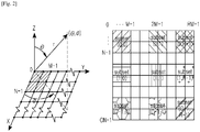
- planar array case for example, array of linear array
- FIG. 2 illustrates a planner array according to an embodiment of the present disclosure.
- the planner array of FIG. 2 consists of c*n linear array each having r*m antenna elements.
- the planner array is partitioned into c*r subarrays each of which consists of M*N elements and is connected to one RF chain.
- analog BF is performed with main direction ( ⁇ 0 , ⁇ 0 ).
- DBF is performed over R*C RF chains, with phase ⁇ r , c on the (r,c)th RF chain.
- Equation (4) G DBF ⁇ ⁇ ⁇ G SABF ⁇ ⁇
- RS Reference Signal
- RS Reference Signal
- An MS selects a best beam (or an index for the best beam) and feeds back the same.
- the best beam (or the index for the best beam) is used for transmission of DL data or a dedicated control message.
- B DL RSs cover the cell, with the main direction of analog BF of ith RS being ⁇ 1 .
- the number of digital BF entries is 2M+1 per each RS with angular spacing ⁇ , and the jth entry corresponds to the direction ⁇ 1 +( j-M ) ⁇ .
- An MS covered by the ith RS beam measures RS power on each subcarrier, and determines the subcarrier with highest signal power.
- a BS can recognize the best DL direction of the MS with respect to a DL direction.
- a BS informs an MS if there is power boost on RS subcarriers, and the MS compensates for this boost value when comparing RS power with respect to different subcarriers.
- each beam has 2M+1 entries.
- the MS sums up received power on each subcarrier and determines the one with highest average power or an index of the beam as the best DL direction.
- Digital BF subcarriers can be subcarriers used for beam training. Also, note that both direction and CQI can be obtained via same RS signal. Also, the BS can reduce the load of RSs by transmitting the beams only toward directions reported by MSs.
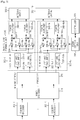
- FIG. 3 illustrates a block diagram of a reception end according to an embodiment of the present disclosure.
- the transmission end uses digital/analog mixed BF and represents a transmission end of an MS and a BS.
- FIG. 3 illustrates the transmission end of FIG. 1 in another embodiment of the present disclosure.
- the transmission end includes K channel encoders 300-1 to 300-K, an MIMO encoder 310, a precoder 320, N T RF paths 330-1 to 330-N T , N T antenna units 350-1 to 350-N T , a beam setting unit 360, and a controller 370.
- Each of K channel encoders 300-1 to 300-K includes a channel encoder and a modulator to encode and modulate a signal to transmit to a reception end.
- the MIMO encoder 310 multiplexes modulation signals provided from the K channel encoders 300-1 to 300-K as signals to transmit via N T streams in order to transmit signals via N T antenna units 350-1 to 350-N T .
- the precoder 320 precodes N T signals provided from the MIMO encoder 310 as precodes for digital BF and provides the same to respective RF paths 330-1 to 330- N T .
- Each of the N T RF paths 330-1 to 330-N T processes a signal provided from the precoder 320 in order to output the signal via a relevant antenna unit 350-1 to 350-N T .
- the N T RF paths 330-1 to 330-N T are configured in the same way. Therefore, the configuration of a first RF path 330-1 is described as a representative in the following.
- the rest of the RF paths 330-2 to 330-NT are configured in the same way as the first RF path 330-1.
- the first RF path 330-1 includes N A IFFT and DAC units 332-11 to 332-1N A , an analog beam forming unit 390, and N A power amplifiers 340-11 to 340-1N A .
- N A is the number of antenna elements forming the antenna unit 1 350-1.
- Each of N A IFFT and DAC units 332-11 to 332-1N A modulates and outputs a signal provided from the precoder 320 depending on a communication scheme.
- each of N A IFFT and DAC units 332-11 to 332-1N A includes an Inverse Fast Fourier Transform (IFFT) operator and a Digital to Analog Converter (DAC).
- the IFFT operator converts a signal provided from the precoder 320 to a signal in a time domain via an IFFT operation.
- the DAC converts the signal in the time domain provided from the IFFT operator to an analog signal. That is, each of N A IFFT and DAC units 332-11 to 332-1N A allocates a resource for an MS with respect to a frequency domain under control of the controller 370.
- the analog beam forming unit 390 changes the transmission beam direction of N A transmission signals provided from N A IFFT and DAC units 332-11 to 332-1N A and outputs the same according to a control signal representing a transmission beam direction provided from the beam setting unit 360.
- the analog beam forming unit 390 includes a plurality of phase shift units 334-11 to 334-1N A , 336-11 to 336-1N A , and couplers 338-11 to 338-1N A .
- Each of the N A IFFT and DAC units 332-11 to 332-1N A divides an output signal into N A signals and outputs the same to respective phase shift units 334-11 to 334-1N A , 336-11 to 336-1N A .
- Each of the phase shift units 334-11 to 334-1N A , 336-11 to 336-1N A shifts the phase of a signal provided from the N A IFFT and DAC units 332-11 to 332-1N A according to a control signal representing a transmission beam direction provided from the beam setting unit 330.
- the couplers 338-11 to 338-1N A couple output signals of the phase shift units 334-11 to 334-1N A , 336-11 to 336-1N A corresponding to an antenna factor and output the same.
- the power amplifiers 340-11 to 340-1N A amplify the power of signals provided from the couplers 338-11 to 338-1N A , and output the same to the outside via the antenna unit 1 350-1.
- the beam setting unit 360 selects a transmission beam direction to use in transmitting a signal and provides a control signal depending on the selected transmission beam direction to the analog beam forming unit 390 under control of the controller 370.
- the beam setting unit 360 provides a control signal corresponding to a transmission beam direction for transmission of an RS or a preamble/midamble or data to the analog beam forming unit 390 under control of the controller 370.
- the beam setting unit 360 selects the transmission beam direction that can obtain an optimal transmission efficiency with a reception end with consideration of channel information depending on each transmission beam direction provided from an MS under control of the controller 370.
- the controller 370 controls the beam setting unit 360 to select the transmission beam direction.
- the controller 370 controls the beam setting unit 360 to transmit an RS or data via each transmission beam direction supportable by the transmission end.
- the controller 370 controls the beam setting unit 360 to select an optimal transmission beam direction with consideration of channel information for a transmission beam direction provided from the reception end.
- the transmission end may be provided with an optimal transmission beam direction selected by the reception end from the reception end.
- the beam setting unit 360 provides a control signal and data depending on the optimal transmission beam direction selected by the reception end to the analog beam forming unit 390.
- the controller 370 of the transmission end may transmit a control message to a counterpart node (for example, serving base station, neighbor BS, or MS).
- a counterpart node for example, serving base station, neighbor BS, or MS.
- the controller 370 controls the beam forming unit 390 to transmit an RS using Equation (6).
- the controller 370 determines a power boost factor using Equation (7) and informs an MS of this.
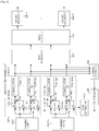
- FIG. 4 illustrates a block diagram of a reception end according to an embodiment of the present disclosure.
- the reception end uses a method that can receive a beam by digital/analog mixed BF, and may represent the reception end of an MS and a BS.
- the reception end includes N R antenna units 400-1 to 400-N R , N R RF paths 410-1 to 410-N R , a post processor 420, an MIMO decoder 430, T channel decoders 440-1 to 440-T, a channel estimator 450, a controller 460, and a beam setting unit 470.
- Each of N R RF paths 410-1 to 410-N R processes a signal received via a relevant antenna unit 400-1 to 400-N R .
- the N R RF paths 410-1 to 410-N R are configured in the same way. Therefore, the configuration of the first RF path 410-1 is described as a representative in the following.
- the rest of the RF paths 410-2 to 410-N R are configured in the same way as the first RF path 410-1.
- the first RF path 410-1 includes an analog beam forming unit 480 and N B IFFT and DAC units 418-11 to 418-1N B .
- N B is the number of antenna elements forming the antenna unit 1 400-1.
- the analog beam forming unit 480 changes the direction of N B reception signals provided from antenna elements forming the antenna unit 1 400-1 depending on a transmission beam direction provided from the beam setting unit 470, and outputs the same.
- the analog beam forming unit 480 includes a plurality of phase shift units 412-11 to 412-1N B , 414-11 to 414-1N B , and couplers 416-11 to 416-1N B .
- Antenna elements forming the antenna unit 1 400-1 divides a reception signal into N B signals and outputs the same to respective phase shift units 412-11 to 412-1N B , 414-11 to 414-1N B .
- Each of the phase shift units 412-11 to 412-1N B , 414-11 to 414-1N B shifts the phase of a signal provided from the antenna elements forming the antenna unit 1 400-1 depending on a reception beam direction provided from the beam setting unit 470.
- the couplers 416-11 to 416-1N B couple output signals of phase shift units 414-11 to 414-1N B , 414-11 to 414-1N B and output the same.
- Each of the NB demodulators 418-11 to 418-1N B demodulates a reception signal provided from the couplers 416-11 to 416-1N B according to a communication scheme, and outputs the same.
- each of the N B demodulators 418-11 to 418-1N B includes an Analog to Digital Converter (ADC) and a Fast Fourier Transform (FFT) operator.
- ADC Analog to Digital Converter
- FFT Fast Fourier Transform
- the ADC converts a reception signal provided from the couplers 416-11 to 416-1N B to a digital signal.
- the FFT operator converts a signal provided from the ADC to a signal in the frequency domain via an FFT operation.
- the post processor 420 post-decodes a signal provided from the N R RF paths 410-1 to 410-N R according to a precoding scheme of the transmission end and provides the same to the MIMO decoder 430.
- the MIMO decoder 430 multiplexes N R reception signals provided from the post processor 420 as T signals and outputs the same such that the T channel decoders 440-1 to 440-T may decode the T signals.
- Each of the T channel decoders 440-1 to 440-T includes a demodulator and a channel decoder to demodulate and decode a signal provided from the transmission end.
- the channel estimator 450 estimates channel information via an RS transmitted by the transmission end via each transmission beam direction. At this point, when a scan event occurs, the channel estimator 450 estimates the channel information for each transmission beam direction.
- the channel information includes at least one of a Signal to Noise Ratio (SNR), a Carrier power Interference and Noise power Ratio (CINR), and a Received Signal Strength Indicator (RSSI).
- SNR Signal to Noise Ratio
- CINR Carrier power Interference and Noise power Ratio
- RSSI Received Signal Strength Indicator
- the controller 460 transmits the channel information for each transmission beam direction estimated by the channel estimator 450 to the transmission end. For example, the controller 460 transmits channel information for transmission beam directions whose channel state is good to the transmission end.
- the controller 460 may transmit channel information for transmission beam directions whose channel state is equal to or greater than a reference value to the transmission end for each reception beam direction.
- the controller 460 may select a transmission beam direction that can obtain an optimal transmission efficiency with the transmission end with consideration of channel information depending on each transmission beam direction estimated by the channel estimator 450.
- the controller 460 selects a transmission beam direction that can obtain an optimal transmission efficiency with the transmission end with consideration of channel information depending on each transmission beam direction estimated by the channel estimator 450.
- the controller 460 calculates average power every subcarrier transmitted by the BS, and selects a best subcarrier having largest average power.
- the function of the beam setting unit may be performed by the controller 370 or 460.
- FIG. 5 illustrates a flowchart of an operation procedure of a base station (BS) according to various embodiments of the present disclosure.
- the BS determines an analog BF direction (step 505), which denotes that the BS can determine directions in advance on which analog BF is to be performed. This denotes that the BS determines a section of degrees by which a relevant direction is divided.
- the BS can inform an MS of the analog BF direction or the MS may possess in advance the analog BF direction determined by the BS.
- the BS selects a digital BF precoder with respect to each analog BF direction (step 510). This denotes that the BS determines 2M+1 digital BF directions with respect to each analog BF direction.
- the BS transmits a DL RS for each analog beam (step 520).
- the BS repeatedly allocates 1 to 2M+1 digital BF precoders N times for consecutive frequency resources (for example, subcarriers) in the frequency domain. Frequency allocation information for subcarriers like 2M-1, N, 2M+1 is determined in advance or broadcast. Also, the BS informs the MS whether a power boost has been applied to an RS. When applied, the MS calculates the signal power of each subcarrier based on the power of a received signal using the power boost factor.
- the BS receives feedback from the MS (step 525).
- the method described above in relation with FIG. 5 under of the present invention may be provided as one or more instructions in one or more software modules, or computer programs stored in an electronic device including a base station.
- FIG. 6 illustrates a flowchart of an operation procedure of an MS according to various embodiments of the present disclosure.
- the MS receives frequency allocation information for subcarriers from a BS (step 605).
- the reception process is selective and the MS may possess the frequency allocation information in advance.
- the MS measures a DL RS transmitted by the BS (step 610).
- the MS selects a best analog beam index and a best digital subcarrier index (beam index) (step 615).
- the MS selects a best precoder (for example, best subcarrier index).
- the MS calculates average power every subcarrier in the frequency domain thereof and selects a best subcarrier having largest average power.
- the MS feeds back the selected analog beam index and digital subcarrier index (beam index) to the BS (step 620).
- the method described above in relation with FIG. 6 under of the present invention may be provided as one or more instructions in one or more software modules, or computer programs stored in an electronic device including a mobile station.
- FIG. 7 illustrates a BF direction according to an embodiment of the present disclosure.
- the BS can recognize that ⁇ of the MS 1 and the MS 2 are 11/24 pi and 13/24 pi, respectively, and the BS can recognize the positions of the MS 1 and the MS 2.
- Embodiments of the present invention can be realized in the form of hardware, software or a combination of hardware and software.
- Such software may be stored in a computer readable storage medium.
- the computer readable storage medium stores one or more programs (software modules), the one or more programs comprising instructions, which when executed by one or more processors in an electronic device, cause the electronic device to perform methods of the present invention.
- Such software may be stored in the form of volatile or non-volatile storage such as, for example, a storage device like a ROM, whether erasable or rewritable or not, or in the form of memory such as, for example, RAM, memory chips, device or integrated circuits or on an optically or magnetically readable medium such as, for example, a CD, DVD, magnetic disk or magnetic tape or the like.
- a storage device like a ROM, whether erasable or rewritable or not
- memory such as, for example, RAM, memory chips, device or integrated circuits or on an optically or magnetically readable medium such as, for example, a CD, DVD, magnetic disk or magnetic tape or the like.
- the storage devices and storage media are embodiments of machine-readable storage that are suitable for storing a program or programs comprising instructions that, when executed, implement embodiments of the present invention.
- Embodiments provide a program comprising code for implementing apparatus or a method as claimed in any one of the claims of this specification
- the present disclosure has an advantage of maximizing a mixed analog/digital BF gain even in any predetermined direction with respect to a main analog/digital beam peripheral direction in an analog/digital mixed BF system.
Landscapes
- Engineering & Computer Science (AREA)
- Signal Processing (AREA)
- Computer Networks & Wireless Communication (AREA)
- Physics & Mathematics (AREA)
- Mathematical Physics (AREA)
- Power Engineering (AREA)
- Mobile Radio Communication Systems (AREA)
- Radio Transmission System (AREA)
Claims (12)
- Verfahren zum Betreiben einer Basisstation, BS, in einem drahtlosen Kommunikationssystem, wobei das Verfahren Folgendes umfasst:Identifizieren (505) einer analogen Strahlformungs(BF)richtung;Identifizieren (515) einer Vielzahl von digitalen BF-Vorcodierern für die identifizierte analoge BF-Richtung; undÜbertragen (520) einer Vielzahl von Downlink-Referenzsignalen, DL-RS, die der Vielzahl von digitalen BF-Vorcodierern entsprechen, über eine Vielzahl von aufeinanderfolgenden Subträgern in der analogen BF-Richtung,wobei die Vielzahl von digitalen BF-Vorcodierern der Vielzahl von aufeinanderfolgenden Subträgern entspricht.
- Verfahren nach Anspruch 1, das des Weiteren Folgendes umfasst:
Empfangen einer Rückmeldung von einer Mobilstation, MS. - Verfahren nach Anspruch 2, wobei die Rückmeldung mindestens eine von der MS identifizierte analoge BF-Richtungsinformation oder digitalen BF-Subträger-Index umfasst,
wobei die mindestens eine analoge BF-Richtungsinformation und/oder der digitale BF-Subträger-Index basierend auf einer geschätzten Kanalinformation über jedes der Vielzahl von der Basisstation übertragenen DL-RS und einer Durchschnittleistung jedes der Vielzahl von aufeinanderfolgenden Subträgern identifiziert wird. - Verfahren nach Anspruch 1, das des Weiteren Folgendes umfasst:
Übertragen von Frequenzzuweisungsinformationen an eine Mobilstation, MS. - Verfahren nach Anspruch 1, das des Weiteren Folgendes umfasst:
wenn eine Leistungsverstärkung an der Vielzahl von DL-RS angewendet ist, Übertragen einer Anzeige an die MS, dass die Leistungsverstärkung angewandt wird. - Verfahren zum Betreiben einer Mobilstation, MS, in einem drahtlosen Kommunikationssystem, wobei das Verfahren Folgendes umfasst:Empfangen (610) von einer Basisstation, BS, einer Vielzahl von Downlink-Referenzsignalen, DL-RS, die einer Vielzahl von digitalen Strahlformungs-Vorcodierern, BF, entspricht, durch eine Vielzahl von aufeinanderfolgenden Subträgern in einer analogen BF-Richtung;Identifizieren (615) eines digitalen BF-Vorcodierers unter der Vielzahl von digitalen BF-Vorcodierern basierend auf der Vielzahl von DL-RS; undÜbertragen (620) einer Rückmeldung zum Anzeigen des identifizierten digitalen BF-Vorcodierers an die BS,wobei die Vielzahl von digitalen BF-Vorcodierern der Vielzahl von aufeinanderfolgenden Subträgern entspricht.
- Verfahren nach Anspruch 6, das des Weiteren Folgendes umfasst:
Empfangen von Frequenzzuweisungsinformationen von der BS. - Verfahren nach Anspruch 6, wobei die Rückmeldung mindestens eine analoge BF-Richtungsinformation oder einen digitalen BF-Subträger-Index umfasst.
- Verfahren nach Anspruch 6, wobei das Identifizieren des digitalen BF-Vorcodierers basierend auf der Vielzahl von DL-RS Folgendes umfasst:Berechnen einer Durchschnittleistung für jede der Vielzahl von aufeinanderfolgenden Subträgern; undIdentifizieren eines Subträgers mit der größten Durchschnittsleistung.
- Verfahren nach Anspruch 6, wobei der digitale BF-Vorcodierer basierend auf einer geschätzten Kanalinformation über jedes der Vielzahl von der Basisstation übertragenen DL-RS und einer Durchschnittleistung jedes der Vielzahl von aufeinanderfolgenden Subträgern identifiziert wird.
- Vorrichtung einer Basisstation, BS, für ein drahtloses Kommunikationssystem, die zum Ausführen des Verfahrens nach einem der Ansprüche 1 bis 5 konfiguriert ist.
- Vorrichtung einer Mobilstation, MS, für ein drahtloses Kommunikationssystem, die zum Ausführen des Verfahrens nach einem der Ansprüche 6 bis 10 konfiguriert ist.
Applications Claiming Priority (2)
| Application Number | Priority Date | Filing Date | Title |
|---|---|---|---|
| KR20120032339A KR20130110396A (ko) | 2012-03-29 | 2012-03-29 | 아날로그/디지털 혼합 빔 포밍 시스템에서 기준 신호 생성을 위한 방법 및 장치 |
| PCT/KR2013/002645 WO2013147551A1 (en) | 2012-03-29 | 2013-03-29 | Method and apparatus for generating reference signal in analog/digital mixed bf system |
Publications (3)
| Publication Number | Publication Date |
|---|---|
| EP2832010A1 EP2832010A1 (de) | 2015-02-04 |
| EP2832010A4 EP2832010A4 (de) | 2015-12-16 |
| EP2832010B1 true EP2832010B1 (de) | 2019-10-09 |
Family
ID=49234943
Family Applications (1)
| Application Number | Title | Priority Date | Filing Date |
|---|---|---|---|
| EP13769642.3A Active EP2832010B1 (de) | 2012-03-29 | 2013-03-29 | Verfahren und vorrichtung zur erzeugung eines referenzsignals in einem analogen/digitalen gemischten bf-system |
Country Status (4)
| Country | Link |
|---|---|
| US (3) | US9125070B2 (de) |
| EP (1) | EP2832010B1 (de) |
| KR (1) | KR20130110396A (de) |
| WO (1) | WO2013147551A1 (de) |
Families Citing this family (50)
| Publication number | Priority date | Publication date | Assignee | Title |
|---|---|---|---|---|
| JP6673824B2 (ja) * | 2013-11-04 | 2020-04-01 | エルジー エレクトロニクス インコーポレイティド | 無線通信システムにおいて信号を送信する方法及び装置 |
| KR102323130B1 (ko) * | 2013-11-27 | 2021-11-10 | 삼성전자 주식회사 | 하이브리드 빔포밍 기반 오픈-루프 mimo 전송 방법 및 장치 |
| KR102130285B1 (ko) * | 2013-12-26 | 2020-07-08 | 삼성전자주식회사 | 제로-포싱 기반의 하이브리드 빔포밍 방법 및 그 장치 |
| CN104796185A (zh) * | 2014-01-21 | 2015-07-22 | 中兴通讯股份有限公司 | 波束信息获取方法、导频波束发送方法、通信节点及系统 |
| EP3123626B1 (de) * | 2014-03-24 | 2019-05-01 | LG Electronics Inc. | Verfahren zur durchführung einer hybriden strahlformung in einem drahtloskommunikationssystem und vorrichtung dafür |
| CN104079335B (zh) * | 2014-07-08 | 2016-05-18 | 北京理工大学 | 一种多小区ofdma网络下鲁棒性的三维波束赋形方法 |
| WO2016045724A1 (en) * | 2014-09-24 | 2016-03-31 | Telefonaktiebolaget L M Ericsson (Publ) | An antenna arrangement for non-linear distortion mitigation |
| US20160135090A1 (en) * | 2014-11-07 | 2016-05-12 | Qualcomm Incorporated | Millimeter wavelength base station beamforming technique advertising and efficient user equipment transmission strategy |
| US9445282B2 (en) | 2014-11-17 | 2016-09-13 | Mediatek Inc. | Transceiver architecture for multiple antenna systems |
| CN105814808B (zh) * | 2014-11-17 | 2020-07-21 | 联发科技股份有限公司 | 波束成形方法和无线装置 |
| AU2014412334B2 (en) * | 2014-11-25 | 2019-05-02 | Telefonaktiebolaget Lm Ericsson (Publ) | A radio transmitter for distortion mitigation |
| CN106033989B (zh) * | 2015-03-12 | 2019-09-17 | 电信科学技术研究院 | 一种混合波束赋形传输方法及网络设备 |
| WO2016153265A1 (ko) * | 2015-03-26 | 2016-09-29 | 엘지전자 주식회사 | 무선 통신 시스템에서 빔 스캐닝 절차를 이용하여 도플러 주파수를 추정하는 방법 및 장치 |
| WO2016182529A1 (en) * | 2015-05-08 | 2016-11-17 | Intel IP Corporation | Reference signals, measurements, and demodulation architectures and methods |
| US10383120B2 (en) * | 2015-05-11 | 2019-08-13 | Acer Incorporated | Device and method of reporting channel information according to beamforming |
| US10090899B2 (en) | 2015-07-29 | 2018-10-02 | Lg Electronics Inc. | Method for determining precoder for hybrid beamforming in wireless communication system, and apparatus therefor |
| ES2744183T3 (es) | 2015-07-31 | 2020-02-24 | Intel Ip Corp | Descubrimiento de red y adquisición de haz para operación de célula de haz |
| WO2017022921A1 (ko) * | 2015-07-31 | 2017-02-09 | 엘지전자 주식회사 | 무선 통신 시스템에서 하이브리드 범포밍을 위한 프리코더 결정 방법 및 이를 위한 장치 |
| US10263805B2 (en) * | 2015-09-28 | 2019-04-16 | Commscope Technologies Llc | Directional wireless drop systems for broadband networks and related methods |
| CN106921423B (zh) * | 2015-12-28 | 2020-02-07 | 电信科学技术研究院 | 一种确定模拟波束的方法和设备 |
| WO2017123060A1 (en) | 2016-01-14 | 2017-07-20 | Samsung Electronics Co., Ltd. | System, method, and apparatus of beam-tracking and beam feedback operation in a beam-forming based system |
| US10284267B2 (en) * | 2016-03-11 | 2019-05-07 | Huawei Technologies Canada Co., Ltd. | System and method for reducing self-interference in a wireless resource |
| US10847879B2 (en) | 2016-03-11 | 2020-11-24 | Huawei Technologies Canada Co., Ltd. | Antenna array structures for half-duplex and full-duplex multiple-input and multiple-output systems |
| CN107306148B (zh) * | 2016-04-22 | 2021-03-16 | 中国移动通信有限公司研究院 | 数字模拟域混合架构下的信号处理方法、基站及终端 |
| US10855350B2 (en) * | 2016-05-12 | 2020-12-01 | Interdigital Patent Holdings, Inc. | Systems and methods for beamforming feedback in mm wave wireless local area networks |
| CN107370524A (zh) * | 2016-05-13 | 2017-11-21 | 电信科学技术研究院 | 一种信号发送方法、装置及设备 |
| US10141993B2 (en) * | 2016-06-16 | 2018-11-27 | Intel Corporation | Modular antenna array beam forming |
| US9806777B1 (en) | 2016-06-24 | 2017-10-31 | Intel Corporation | Communication device and a method for beamforming |
| WO2018026223A1 (ko) * | 2016-08-03 | 2018-02-08 | 엘지전자 주식회사 | 무선 통신 시스템에서 단말에 의해 수행되는 파워 헤드룸 보고 방법 및 상기 방법을 이용하는 단말 |
| WO2018027936A1 (en) * | 2016-08-12 | 2018-02-15 | Qualcomm Incorporated | Uplink multiple-input multiple-output (mimo) scheduling using beamformed reference signals |
| US10763931B2 (en) | 2016-09-27 | 2020-09-01 | Apple Inc. | Communication device and a method for hybrid beamforming |
| CN107896122B (zh) | 2016-09-30 | 2020-10-20 | 电信科学技术研究院 | 一种波束扫描和搜索跟踪方法及装置 |
| US10582397B2 (en) * | 2016-11-09 | 2020-03-03 | Qualcomm Incorporated | Beam refinement reference signal transmissions during control symbol |
| US11374634B2 (en) * | 2016-11-30 | 2022-06-28 | Telefonaktiebolaget Lm Ericsson (Publ) | Method and device for transmitting information |
| CN106603130B (zh) * | 2016-12-20 | 2020-07-10 | 西安电子科技大学 | 一种大规模mimo系统中数模混合预编码方法 |
| JP2018117274A (ja) * | 2017-01-19 | 2018-07-26 | 富士通株式会社 | 無線基地局、無線通信システム、無線通信方法、及び無線端末 |
| CN107018099B (zh) * | 2017-03-07 | 2020-06-09 | 上海交通大学 | 一种针对毫米波多用户mimo系统的时变信道估计方法 |
| WO2018183131A1 (en) * | 2017-03-27 | 2018-10-04 | Idac Holdings, Inc. | Adaptive digital precoder codebook configurations for mmwave communication based on hybrid beamforming |
| US11258496B2 (en) * | 2017-04-13 | 2022-02-22 | Sony Corporation | Communication devices and methods with hybrid beamforming |
| CN107104719B (zh) * | 2017-05-16 | 2020-04-24 | 东南大学 | 一种基于几何构造的毫米波数字模拟混合预编码设计方法 |
| CN110024475B (zh) | 2017-08-03 | 2023-09-22 | 联发科技股份有限公司 | 信道访问方法 |
| US10256894B2 (en) | 2017-09-11 | 2019-04-09 | Qualcomm Incorporated | Hybrid beam former |
| WO2019135654A1 (en) | 2018-01-05 | 2019-07-11 | Samsung Electronics Co., Ltd. | Apparatus and method of beam recovery on secondary cell |
| US10270510B1 (en) | 2018-03-19 | 2019-04-23 | Mitsubishi Electric Research Laboratories, Inc. | Digital beamforming transmitter array system with hardware sharing and reduction |
| KR102441982B1 (ko) | 2018-07-05 | 2022-09-13 | 삼성전자주식회사 | 무선 통신 시스템에서 빔 포밍을 수행하는 방법 및 장치 |
| CN111106864B (zh) * | 2018-11-16 | 2023-02-24 | 维沃移动通信有限公司 | 上行波束训练方法、终端设备和网络侧设备 |
| US10979117B2 (en) * | 2018-12-15 | 2021-04-13 | MMRFIC Technology Pvt. Ltd. | Method, system and apparatus for beam forming in a radio frequency transceiver with reduced complexity |
| US11638281B2 (en) * | 2020-11-19 | 2023-04-25 | Samsung Electronics Co., Ltd. | Method and apparatus for a user equipment sub-chain beam codebook design and operation |
| CN113225113B (zh) * | 2021-03-25 | 2022-07-05 | 深圳航天科技创新研究院 | 预编码方法、装置、系统及计算机可读存储介质 |
| CN116054894B (zh) * | 2023-01-10 | 2024-08-16 | 电子科技大学 | 一种抑制波束斜视影响的混合预编码方法 |
Family Cites Families (19)
| Publication number | Priority date | Publication date | Assignee | Title |
|---|---|---|---|---|
| KR100655661B1 (ko) * | 2004-12-09 | 2006-12-11 | 한국전자통신연구원 | 배열 안테나 기지국의 시공간 다중 사용자 신호 검출 장치및 그 방법 |
| CN101185200B (zh) * | 2005-11-14 | 2011-07-20 | 桥扬科技有限公司 | 用于蜂窝通信和广播的多天线系统 |
| US8325852B2 (en) * | 2007-06-08 | 2012-12-04 | Samsung Electronics Co., Ltd. | CDD precoding for open loop SU MIMO |
| CN101933264A (zh) * | 2008-02-01 | 2010-12-29 | 夏普株式会社 | 发送机、接收机、发送方法和接收方法 |
| KR20110016948A (ko) * | 2008-06-27 | 2011-02-18 | 교세라 가부시키가이샤 | 무선통신장치 및 무선통신방법 |
| WO2010002734A2 (en) * | 2008-06-30 | 2010-01-07 | Interdigital Patent Holdings, Inc. | Method and apparatus to support single user (su) and multiuser (mu) beamforming with antenna array groups |
| US7773030B2 (en) * | 2008-07-31 | 2010-08-10 | Samsung Electronics Co., Ltd. | Method and system for antenna training and communication protocol for multi-beamforming communication |
| US20100061360A1 (en) * | 2008-09-10 | 2010-03-11 | Texas Instruments Incorporated | Dedicated reference signal structures for spatial multiplexing beamforming |
| GB2467143B (en) * | 2009-01-22 | 2011-04-06 | Toshiba Res Europ Ltd | Wireless commication method and apparatus |
| US8754810B2 (en) * | 2009-02-02 | 2014-06-17 | Commonwealth Scientific And Industrial Research Organisation | Hybrid adaptive antenna array |
| US8867495B2 (en) * | 2009-03-20 | 2014-10-21 | Qualcomm Incorporated | Feedback mechanisms for beamforming operation |
| US8891647B2 (en) * | 2009-10-30 | 2014-11-18 | Futurewei Technologies, Inc. | System and method for user specific antenna down tilt in wireless cellular networks |
| US8872719B2 (en) * | 2009-11-09 | 2014-10-28 | Linear Signal, Inc. | Apparatus, system, and method for integrated modular phased array tile configuration |
| EP2388931B1 (de) * | 2010-05-21 | 2017-09-13 | Imec | Verfahren und System zur gemischten analogen/digitalen Strahlformung in drahtlosen Kommunikationssystemen |
| KR101839812B1 (ko) | 2011-08-11 | 2018-03-19 | 삼성전자주식회사 | 혼합 아날로그/디지털 빔포밍을 위한 방법 및 장치 |
| EP3567736A1 (de) * | 2011-08-19 | 2019-11-13 | Quintel Cayman Limited | Verfahren und vorrichtung zur bereitstellung einer räumlichen strahlformung auf einer hebeplattform |
| US20130057432A1 (en) * | 2011-09-02 | 2013-03-07 | Samsung Electronics Co., Ltd. | Method and apparatus for beam broadening for phased antenna arrays using multi-beam sub-arrays |
| US9124361B2 (en) * | 2011-10-06 | 2015-09-01 | Raytheon Company | Scalable, analog monopulse network |
| US9444534B2 (en) * | 2012-02-06 | 2016-09-13 | Samsung Electronics Co., Ltd. | Apparatus and method for low complexity spatial division multiple access in a millimeter wave mobile communication system |
-
2012
- 2012-03-29 KR KR20120032339A patent/KR20130110396A/ko not_active Withdrawn
-
2013
- 2013-03-29 WO PCT/KR2013/002645 patent/WO2013147551A1/en not_active Ceased
- 2013-03-29 EP EP13769642.3A patent/EP2832010B1/de active Active
- 2013-03-29 US US13/853,699 patent/US9125070B2/en active Active
-
2015
- 2015-08-27 US US14/838,271 patent/US9531517B2/en active Active
-
2016
- 2016-12-24 US US15/390,477 patent/US10320540B2/en active Active
Non-Patent Citations (1)
| Title |
|---|
| None * |
Also Published As
| Publication number | Publication date |
|---|---|
| US10320540B2 (en) | 2019-06-11 |
| EP2832010A4 (de) | 2015-12-16 |
| US20170111149A1 (en) | 2017-04-20 |
| US9531517B2 (en) | 2016-12-27 |
| US20150372794A1 (en) | 2015-12-24 |
| WO2013147551A1 (en) | 2013-10-03 |
| KR20130110396A (ko) | 2013-10-10 |
| US20130258972A1 (en) | 2013-10-03 |
| EP2832010A1 (de) | 2015-02-04 |
| US9125070B2 (en) | 2015-09-01 |
Similar Documents
| Publication | Publication Date | Title |
|---|---|---|
| EP2832010B1 (de) | Verfahren und vorrichtung zur erzeugung eines referenzsignals in einem analogen/digitalen gemischten bf-system | |
| US10230440B2 (en) | Communication method and apparatus using beamforming in a wireless communication system | |
| EP2845328B1 (de) | Verfahren und vorrichtung zur strahlformung in einem drahtlosen kommunikationssystem | |
| US8843150B2 (en) | Beamforming method and apparatus for acquiring transmission beam diversity in a wireless communication system | |
| US9203497B2 (en) | Apparatus and method for selecting transmit and receive beam in a wireless communication system | |
| KR102100748B1 (ko) | 무선 통신 시스템에서 빔 그룹핑을 통한 레퍼런스 신호 송수신 방법 및 장치 | |
| US9603156B2 (en) | Apparatus and method for transmission/reception in radio communication system | |
| US9893789B2 (en) | Method of transmitting a reference signal in a wireless communication system and apparatus therefor | |
| US9800304B2 (en) | Method of feedback for beamforming in a wireless communication system and apparatus therefor | |
| US10028153B2 (en) | Efficient beam scanning for high-frequency wireless networks | |
| KR101966724B1 (ko) | 빔 포밍 기반의 무선통신시스템에서 빔을 선택하기 위한 장치 및 방법 | |
| US20130163457A1 (en) | Channel state information feedback apparatus and method in wireless communication system operating in fdd mode | |
| EP3427398B1 (de) | Verfahren und vorrichtung zur kanalsondierung für ein drahtloskommunikationsnetzwerk | |
| EP3316493A1 (de) | Trainingsstrahlübertragungsverfahren, -vorrichtung und -system | |
| EP3076563A1 (de) | Auf strahlformung basiertes hybrides mimo-übertragungsverfahren und vorrichtung dafür | |
| US11101859B2 (en) | Signal transmission method and device using beamforming in wireless communication system | |
| US7920646B2 (en) | Method for selecting switched beam using pilot signal and system thereof | |
| EP2859723B1 (de) | Mimo-signalübertragungs- und -empfangsvorrichtung sowie system mit mindestens einer solchen vorrichtung | |
| CN108540190A (zh) | 波束赋形方法和装置 | |
| US12341593B2 (en) | Apparatus comprising at least one processor |
Legal Events
| Date | Code | Title | Description |
|---|---|---|---|
| PUAI | Public reference made under article 153(3) epc to a published international application that has entered the european phase |
Free format text: ORIGINAL CODE: 0009012 |
|
| 17P | Request for examination filed |
Effective date: 20140929 |
|
| AK | Designated contracting states |
Kind code of ref document: A1 Designated state(s): AL AT BE BG CH CY CZ DE DK EE ES FI FR GB GR HR HU IE IS IT LI LT LU LV MC MK MT NL NO PL PT RO RS SE SI SK SM TR |
|
| AX | Request for extension of the european patent |
Extension state: BA ME |
|
| DAX | Request for extension of the european patent (deleted) | ||
| RA4 | Supplementary search report drawn up and despatched (corrected) |
Effective date: 20151117 |
|
| RIC1 | Information provided on ipc code assigned before grant |
Ipc: H04B 7/06 20060101AFI20151111BHEP Ipc: H04W 16/28 20090101ALI20151111BHEP |
|
| STAA | Information on the status of an ep patent application or granted ep patent |
Free format text: STATUS: EXAMINATION IS IN PROGRESS |
|
| 17Q | First examination report despatched |
Effective date: 20180209 |
|
| REG | Reference to a national code |
Ref country code: DE Ref legal event code: R079 Ref document number: 602013061500 Country of ref document: DE Free format text: PREVIOUS MAIN CLASS: H04B0007040000 Ipc: H04W0072040000 |
|
| RIC1 | Information provided on ipc code assigned before grant |
Ipc: H04B 7/06 20060101ALI20190411BHEP Ipc: H04W 72/04 20090101AFI20190411BHEP Ipc: H04W 16/28 20090101ALI20190411BHEP Ipc: H04L 5/00 20060101ALI20190411BHEP |
|
| GRAP | Despatch of communication of intention to grant a patent |
Free format text: ORIGINAL CODE: EPIDOSNIGR1 |
|
| STAA | Information on the status of an ep patent application or granted ep patent |
Free format text: STATUS: GRANT OF PATENT IS INTENDED |
|
| INTG | Intention to grant announced |
Effective date: 20190527 |
|
| RAP1 | Party data changed (applicant data changed or rights of an application transferred) |
Owner name: SAMSUNG ELECTRONICS CO., LTD. |
|
| RIN1 | Information on inventor provided before grant (corrected) |
Inventor name: HAN, SHUANGFENG Inventor name: PARK, JEONG-HO Inventor name: KIM, TAE-YOUNG |
|
| GRAS | Grant fee paid |
Free format text: ORIGINAL CODE: EPIDOSNIGR3 |
|
| GRAA | (expected) grant |
Free format text: ORIGINAL CODE: 0009210 |
|
| STAA | Information on the status of an ep patent application or granted ep patent |
Free format text: STATUS: THE PATENT HAS BEEN GRANTED |
|
| AK | Designated contracting states |
Kind code of ref document: B1 Designated state(s): AL AT BE BG CH CY CZ DE DK EE ES FI FR GB GR HR HU IE IS IT LI LT LU LV MC MK MT NL NO PL PT RO RS SE SI SK SM TR |
|
| REG | Reference to a national code |
Ref country code: GB Ref legal event code: FG4D |
|
| REG | Reference to a national code |
Ref country code: CH Ref legal event code: EP |
|
| REG | Reference to a national code |
Ref country code: IE Ref legal event code: FG4D |
|
| REG | Reference to a national code |
Ref country code: DE Ref legal event code: R096 Ref document number: 602013061500 Country of ref document: DE |
|
| REG | Reference to a national code |
Ref country code: AT Ref legal event code: REF Ref document number: 1190310 Country of ref document: AT Kind code of ref document: T Effective date: 20191115 |
|
| REG | Reference to a national code |
Ref country code: NL Ref legal event code: MP Effective date: 20191009 |
|
| REG | Reference to a national code |
Ref country code: LT Ref legal event code: MG4D |
|
| REG | Reference to a national code |
Ref country code: AT Ref legal event code: MK05 Ref document number: 1190310 Country of ref document: AT Kind code of ref document: T Effective date: 20191009 |
|
| PG25 | Lapsed in a contracting state [announced via postgrant information from national office to epo] |
Ref country code: NO Free format text: LAPSE BECAUSE OF FAILURE TO SUBMIT A TRANSLATION OF THE DESCRIPTION OR TO PAY THE FEE WITHIN THE PRESCRIBED TIME-LIMIT Effective date: 20200109 Ref country code: PL Free format text: LAPSE BECAUSE OF FAILURE TO SUBMIT A TRANSLATION OF THE DESCRIPTION OR TO PAY THE FEE WITHIN THE PRESCRIBED TIME-LIMIT Effective date: 20191009 Ref country code: AT Free format text: LAPSE BECAUSE OF FAILURE TO SUBMIT A TRANSLATION OF THE DESCRIPTION OR TO PAY THE FEE WITHIN THE PRESCRIBED TIME-LIMIT Effective date: 20191009 Ref country code: SE Free format text: LAPSE BECAUSE OF FAILURE TO SUBMIT A TRANSLATION OF THE DESCRIPTION OR TO PAY THE FEE WITHIN THE PRESCRIBED TIME-LIMIT Effective date: 20191009 Ref country code: LV Free format text: LAPSE BECAUSE OF FAILURE TO SUBMIT A TRANSLATION OF THE DESCRIPTION OR TO PAY THE FEE WITHIN THE PRESCRIBED TIME-LIMIT Effective date: 20191009 Ref country code: BG Free format text: LAPSE BECAUSE OF FAILURE TO SUBMIT A TRANSLATION OF THE DESCRIPTION OR TO PAY THE FEE WITHIN THE PRESCRIBED TIME-LIMIT Effective date: 20200109 Ref country code: FI Free format text: LAPSE BECAUSE OF FAILURE TO SUBMIT A TRANSLATION OF THE DESCRIPTION OR TO PAY THE FEE WITHIN THE PRESCRIBED TIME-LIMIT Effective date: 20191009 Ref country code: GR Free format text: LAPSE BECAUSE OF FAILURE TO SUBMIT A TRANSLATION OF THE DESCRIPTION OR TO PAY THE FEE WITHIN THE PRESCRIBED TIME-LIMIT Effective date: 20200110 Ref country code: NL Free format text: LAPSE BECAUSE OF FAILURE TO SUBMIT A TRANSLATION OF THE DESCRIPTION OR TO PAY THE FEE WITHIN THE PRESCRIBED TIME-LIMIT Effective date: 20191009 Ref country code: PT Free format text: LAPSE BECAUSE OF FAILURE TO SUBMIT A TRANSLATION OF THE DESCRIPTION OR TO PAY THE FEE WITHIN THE PRESCRIBED TIME-LIMIT Effective date: 20200210 Ref country code: ES Free format text: LAPSE BECAUSE OF FAILURE TO SUBMIT A TRANSLATION OF THE DESCRIPTION OR TO PAY THE FEE WITHIN THE PRESCRIBED TIME-LIMIT Effective date: 20191009 Ref country code: LT Free format text: LAPSE BECAUSE OF FAILURE TO SUBMIT A TRANSLATION OF THE DESCRIPTION OR TO PAY THE FEE WITHIN THE PRESCRIBED TIME-LIMIT Effective date: 20191009 |
|
| PG25 | Lapsed in a contracting state [announced via postgrant information from national office to epo] |
Ref country code: HR Free format text: LAPSE BECAUSE OF FAILURE TO SUBMIT A TRANSLATION OF THE DESCRIPTION OR TO PAY THE FEE WITHIN THE PRESCRIBED TIME-LIMIT Effective date: 20191009 Ref country code: IS Free format text: LAPSE BECAUSE OF FAILURE TO SUBMIT A TRANSLATION OF THE DESCRIPTION OR TO PAY THE FEE WITHIN THE PRESCRIBED TIME-LIMIT Effective date: 20200224 Ref country code: RS Free format text: LAPSE BECAUSE OF FAILURE TO SUBMIT A TRANSLATION OF THE DESCRIPTION OR TO PAY THE FEE WITHIN THE PRESCRIBED TIME-LIMIT Effective date: 20191009 |
|
| PG25 | Lapsed in a contracting state [announced via postgrant information from national office to epo] |
Ref country code: AL Free format text: LAPSE BECAUSE OF FAILURE TO SUBMIT A TRANSLATION OF THE DESCRIPTION OR TO PAY THE FEE WITHIN THE PRESCRIBED TIME-LIMIT Effective date: 20191009 |
|
| REG | Reference to a national code |
Ref country code: DE Ref legal event code: R097 Ref document number: 602013061500 Country of ref document: DE |
|
| PG2D | Information on lapse in contracting state deleted |
Ref country code: IS |
|
| PG25 | Lapsed in a contracting state [announced via postgrant information from national office to epo] |
Ref country code: CZ Free format text: LAPSE BECAUSE OF FAILURE TO SUBMIT A TRANSLATION OF THE DESCRIPTION OR TO PAY THE FEE WITHIN THE PRESCRIBED TIME-LIMIT Effective date: 20191009 Ref country code: RO Free format text: LAPSE BECAUSE OF FAILURE TO SUBMIT A TRANSLATION OF THE DESCRIPTION OR TO PAY THE FEE WITHIN THE PRESCRIBED TIME-LIMIT Effective date: 20191009 Ref country code: EE Free format text: LAPSE BECAUSE OF FAILURE TO SUBMIT A TRANSLATION OF THE DESCRIPTION OR TO PAY THE FEE WITHIN THE PRESCRIBED TIME-LIMIT Effective date: 20191009 Ref country code: DK Free format text: LAPSE BECAUSE OF FAILURE TO SUBMIT A TRANSLATION OF THE DESCRIPTION OR TO PAY THE FEE WITHIN THE PRESCRIBED TIME-LIMIT Effective date: 20191009 Ref country code: IS Free format text: LAPSE BECAUSE OF FAILURE TO SUBMIT A TRANSLATION OF THE DESCRIPTION OR TO PAY THE FEE WITHIN THE PRESCRIBED TIME-LIMIT Effective date: 20200209 |
|
| PLBE | No opposition filed within time limit |
Free format text: ORIGINAL CODE: 0009261 |
|
| STAA | Information on the status of an ep patent application or granted ep patent |
Free format text: STATUS: NO OPPOSITION FILED WITHIN TIME LIMIT |
|
| PG25 | Lapsed in a contracting state [announced via postgrant information from national office to epo] |
Ref country code: IT Free format text: LAPSE BECAUSE OF FAILURE TO SUBMIT A TRANSLATION OF THE DESCRIPTION OR TO PAY THE FEE WITHIN THE PRESCRIBED TIME-LIMIT Effective date: 20191009 Ref country code: SM Free format text: LAPSE BECAUSE OF FAILURE TO SUBMIT A TRANSLATION OF THE DESCRIPTION OR TO PAY THE FEE WITHIN THE PRESCRIBED TIME-LIMIT Effective date: 20191009 Ref country code: SK Free format text: LAPSE BECAUSE OF FAILURE TO SUBMIT A TRANSLATION OF THE DESCRIPTION OR TO PAY THE FEE WITHIN THE PRESCRIBED TIME-LIMIT Effective date: 20191009 |
|
| 26N | No opposition filed |
Effective date: 20200710 |
|
| PG25 | Lapsed in a contracting state [announced via postgrant information from national office to epo] |
Ref country code: MC Free format text: LAPSE BECAUSE OF FAILURE TO SUBMIT A TRANSLATION OF THE DESCRIPTION OR TO PAY THE FEE WITHIN THE PRESCRIBED TIME-LIMIT Effective date: 20191009 |
|
| REG | Reference to a national code |
Ref country code: CH Ref legal event code: PL |
|
| PG25 | Lapsed in a contracting state [announced via postgrant information from national office to epo] |
Ref country code: SI Free format text: LAPSE BECAUSE OF FAILURE TO SUBMIT A TRANSLATION OF THE DESCRIPTION OR TO PAY THE FEE WITHIN THE PRESCRIBED TIME-LIMIT Effective date: 20191009 |
|
| REG | Reference to a national code |
Ref country code: BE Ref legal event code: MM Effective date: 20200331 |
|
| PG25 | Lapsed in a contracting state [announced via postgrant information from national office to epo] |
Ref country code: LU Free format text: LAPSE BECAUSE OF NON-PAYMENT OF DUE FEES Effective date: 20200329 |
|
| PG25 | Lapsed in a contracting state [announced via postgrant information from national office to epo] |
Ref country code: CH Free format text: LAPSE BECAUSE OF NON-PAYMENT OF DUE FEES Effective date: 20200331 Ref country code: LI Free format text: LAPSE BECAUSE OF NON-PAYMENT OF DUE FEES Effective date: 20200331 Ref country code: IE Free format text: LAPSE BECAUSE OF NON-PAYMENT OF DUE FEES Effective date: 20200329 |
|
| PG25 | Lapsed in a contracting state [announced via postgrant information from national office to epo] |
Ref country code: BE Free format text: LAPSE BECAUSE OF NON-PAYMENT OF DUE FEES Effective date: 20200331 |
|
| PG25 | Lapsed in a contracting state [announced via postgrant information from national office to epo] |
Ref country code: TR Free format text: LAPSE BECAUSE OF FAILURE TO SUBMIT A TRANSLATION OF THE DESCRIPTION OR TO PAY THE FEE WITHIN THE PRESCRIBED TIME-LIMIT Effective date: 20191009 Ref country code: MT Free format text: LAPSE BECAUSE OF FAILURE TO SUBMIT A TRANSLATION OF THE DESCRIPTION OR TO PAY THE FEE WITHIN THE PRESCRIBED TIME-LIMIT Effective date: 20191009 Ref country code: CY Free format text: LAPSE BECAUSE OF FAILURE TO SUBMIT A TRANSLATION OF THE DESCRIPTION OR TO PAY THE FEE WITHIN THE PRESCRIBED TIME-LIMIT Effective date: 20191009 |
|
| PG25 | Lapsed in a contracting state [announced via postgrant information from national office to epo] |
Ref country code: MK Free format text: LAPSE BECAUSE OF FAILURE TO SUBMIT A TRANSLATION OF THE DESCRIPTION OR TO PAY THE FEE WITHIN THE PRESCRIBED TIME-LIMIT Effective date: 20191009 |
|
| PG25 | Lapsed in a contracting state [announced via postgrant information from national office to epo] |
Ref country code: FR Free format text: LAPSE BECAUSE OF NON-PAYMENT OF DUE FEES Effective date: 20200331 |
|
| PGFP | Annual fee paid to national office [announced via postgrant information from national office to epo] |
Ref country code: GB Payment date: 20260224 Year of fee payment: 14 |
|
| PGFP | Annual fee paid to national office [announced via postgrant information from national office to epo] |
Ref country code: DE Payment date: 20260220 Year of fee payment: 14 |