EP2832241B1 - Dispositif et procédé de condensation de vapeur dans une chambre à vide - Google Patents
Dispositif et procédé de condensation de vapeur dans une chambre à vide Download PDFInfo
- Publication number
- EP2832241B1 EP2832241B1 EP14179208.5A EP14179208A EP2832241B1 EP 2832241 B1 EP2832241 B1 EP 2832241B1 EP 14179208 A EP14179208 A EP 14179208A EP 2832241 B1 EP2832241 B1 EP 2832241B1
- Authority
- EP
- European Patent Office
- Prior art keywords
- vacuum
- vapor
- chamber
- steam
- coolant
- Prior art date
- Legal status (The legal status is an assumption and is not a legal conclusion. Google has not performed a legal analysis and makes no representation as to the accuracy of the status listed.)
- Active
Links
Images




Classifications
-
- A—HUMAN NECESSITIES
- A21—BAKING; EDIBLE DOUGHS
- A21D—TREATMENT OF FLOUR OR DOUGH FOR BAKING, e.g. BY ADDITION OF MATERIALS; BAKING; BAKERY PRODUCTS
- A21D15/00—Improving finished, partly finished or par-baked bakery products
- A21D15/02—Improving finished, partly finished or par-baked bakery products by cooling, e.g. refrigeration or freezing
-
- A—HUMAN NECESSITIES
- A23—FOODS OR FOODSTUFFS; TREATMENT THEREOF, NOT COVERED BY OTHER CLASSES
- A23B—PRESERVATION OF FOODS, FOODSTUFFS OR NON-ALCOHOLIC BEVERAGES; CHEMICAL RIPENING OF FRUIT OR VEGETABLES
- A23B2/00—Preservation of foods or foodstuffs, in general
- A23B2/70—Preservation of foods or foodstuffs, in general by treatment with chemicals
- A23B2/704—Preservation of foods or foodstuffs, in general by treatment with chemicals in the form of gases, e.g. fumigation; Compositions or apparatus therefor
- A23B2/708—Preservation of foods or foodstuffs, in general by treatment with chemicals in the form of gases, e.g. fumigation; Compositions or apparatus therefor in a controlled atmosphere, e.g. partial vacuum, comprising only CO2, N2, O2 or H2O
-
- A—HUMAN NECESSITIES
- A23—FOODS OR FOODSTUFFS; TREATMENT THEREOF, NOT COVERED BY OTHER CLASSES
- A23B—PRESERVATION OF FOODS, FOODSTUFFS OR NON-ALCOHOLIC BEVERAGES; CHEMICAL RIPENING OF FRUIT OR VEGETABLES
- A23B2/00—Preservation of foods or foodstuffs, in general
- A23B2/80—Freezing; Subsequent thawing; Cooling
-
- A—HUMAN NECESSITIES
- A23—FOODS OR FOODSTUFFS; TREATMENT THEREOF, NOT COVERED BY OTHER CLASSES
- A23B—PRESERVATION OF FOODS, FOODSTUFFS OR NON-ALCOHOLIC BEVERAGES; CHEMICAL RIPENING OF FRUIT OR VEGETABLES
- A23B2/00—Preservation of foods or foodstuffs, in general
- A23B2/80—Freezing; Subsequent thawing; Cooling
- A23B2/805—Materials not being transported through or in the apparatus with or without shaping, e.g. in the form of powders, granules or flakes
- A23B2/8055—Materials not being transported through or in the apparatus with or without shaping, e.g. in the form of powders, granules or flakes with packages or with shaping in the form of blocks or portions
-
- B—PERFORMING OPERATIONS; TRANSPORTING
- B01—PHYSICAL OR CHEMICAL PROCESSES OR APPARATUS IN GENERAL
- B01D—SEPARATION
- B01D5/00—Condensation of vapours; Recovering volatile solvents by condensation
- B01D5/0033—Other features
- B01D5/0045—Vacuum condensation
-
- F—MECHANICAL ENGINEERING; LIGHTING; HEATING; WEAPONS; BLASTING
- F25—REFRIGERATION OR COOLING; COMBINED HEATING AND REFRIGERATION SYSTEMS; HEAT PUMP SYSTEMS; MANUFACTURE OR STORAGE OF ICE; LIQUEFACTION SOLIDIFICATION OF GASES
- F25D—REFRIGERATORS; COLD ROOMS; ICE-BOXES; COOLING OR FREEZING APPARATUS NOT OTHERWISE PROVIDED FOR
- F25D31/00—Other cooling or freezing apparatus
-
- F—MECHANICAL ENGINEERING; LIGHTING; HEATING; WEAPONS; BLASTING
- F28—HEAT EXCHANGE IN GENERAL
- F28B—STEAM OR VAPOUR CONDENSERS
- F28B3/00—Condensers in which the steam or vapour comes into direct contact with the cooling medium
- F28B3/06—Condensers in which the steam or vapour comes into direct contact with the cooling medium by injecting the steam or vapour into the cooling liquid
-
- F—MECHANICAL ENGINEERING; LIGHTING; HEATING; WEAPONS; BLASTING
- F28—HEAT EXCHANGE IN GENERAL
- F28B—STEAM OR VAPOUR CONDENSERS
- F28B9/00—Auxiliary systems, arrangements, or devices
- F28B9/02—Auxiliary systems, arrangements, or devices for feeding steam or vapour to condensers
Definitions
- the invention relates to a vacuum cooling device for food, in particular baked goods, which is suitable for the condensation of a vapor, in particular water vapor.
- a vacuum cooling system for cooling food, in particular baked goods, for example freshly baked bread under a negative pressure comprises a vacuum chamber which is designed to hold the fresh food for cooling it; a vacuum source, such as a vacuum pump, connected to the vacuum chamber for ejecting steam from the vacuum chamber and creating a vacuum in the vacuum chamber, and a steam condenser.
- Such a device contains a tube coil or tube bundle arranged in a water container, in which the vapors to be condensed circulate.
- the coil is fed into a receptacle, which is used to hold the condensate. If the vapors in the coil are not fully condensed by the water bath, the vapors collecting in the receptacle can be condensed in an auxiliary condenser.
- This auxiliary condenser is also arranged in the water container within a displacement body.
- the auxiliary capacitor may contain an absorbent through which the moisture is absorbed.
- a condenser for high pressure steam is off for steam engines WO97 / 32113 known, which consists of a pressure vessel in which steam is introduced via a steam supply line. The steam is fed directly into a water bath via a distributor.
- the distributor has a plurality of Distribution pipes that protrude into the water bath.
- the manifolds are in direct contact with the water bath through a plurality of small openings, so that steam in the form of bubbles is introduced through the openings into the water bath, where it condenses.
- Hot and moist foods can be cooled very efficiently by evacuation in a vacuum chamber, which means that only a short cooling time is required.
- very large volumes of steam are generated during the evacuation process, which can be a multiple of the chamber volume.
- the steam volume can be, for example, up to 100 times the chamber volume.
- the performance of the vacuum pump is determined by the volume of steam. This means that the vacuum pump must be designed in such a way that the entire amount of steam leaves the vacuum chamber via the vacuum pump.
- An example of a vacuum pump 1 for a vacuum cooling chamber 2 is shown in FIG JP11-211314 shown.
- the vacuum pump 1 is designed according to the principle of a Venturi pump, which sucks the air out of the vacuum cooling chamber by means of the water pressure of the water flowing through the Venturi nozzle of the Venturi pump. After this in the JP11-211314 The principle shown is that the air from the vacuum cooling chamber is taken up in a water stream and transported away. No steam condensation occurs with this process.
- the power of the water circulation pump 8, which is required for the operation of the venturi pump 1, must be designed for the entire air flow containing steam, and must therefore be of a correspondingly large size.
- steam condensers are installed in the vacuum lines.
- An example of such a solution is in the US 2,696,775 shown.
- US 2,696,775 shows a vacuum chamber for cooling food, which is combined with an oven. After the baking process is complete, the baked goods are evacuated. For this purpose, the steam is sucked off via a line, introduced into a condenser and then fed to the vacuum pump.
- the condenser is located between the vacuum chamber and the vacuum pump and not at the bottom of the vacuum chamber so that the steam does not come into contact with the water bath.
- Another example of a heat exchanger upstream of a Venturi pump, in which steam condensation takes place, is shown in JP2001-221546 shown. Although these steam condensers prevent some of the steam from reaching the downstream vacuum pump, the vacuum pump must circulate the entire uncondensed steam volume flow out of the vacuum container.
- the DE 2902270 relates to a method for cooling baked goods by reducing the pressure in a cooling chamber.
- steam is sucked out of the cooling chamber by means of a vacuum pump.
- the cooling is controlled in such a way that the pressure is reduced to a predetermined setpoint and then suctioned off to the next lower setpoint in a second pressure reduction phase if the measured pressure during a predetermined time interval .DELTA.t the setpoint by no more than a predetermined value ⁇ p exceeds.
- oven-baked goods can be cooled to ambient temperature within a few minutes so that they are cut-resistant and no longer form condensate when packaged in plastic bags.
- the in the DE 2902270 does not cause a change in the power requirement of the vacuum pump, it only allows a more precise control of the vacuum cooling process. A more precise control of the vacuum cooling process can shorten the operating time. As a result, the total energy requirement of the vacuum cooling device per batch can be reduced, but this has no or only a minor effect on the required power of the vacuum pump.
- the DE 2 301 807 relates to a method for cooling and / or drying wet foods under vacuum, taking into account the temperature of the food or the atmosphere, the pressure, the amount of moisture in the atmosphere or in the food after cooling, the degree of saturation of the atmosphere and the time .
- This document also relates to an improvement in the regulation of the vacuum cooling device, which takes into account a large number of parameters.
- DE 10 2008 035 068 A1 relates to a process for the production of baked goods or deep-fried products, in which a high relative humidity is maintained throughout the dough processing and dough processing and the baked hot baked goods are subjected to a vacuum cooling process.
- the relative humidity should be greater than or equal to 96%.
- AT400279B describes a process for the production and preservation of prebaked baked goods.
- the dough pieces are partially baked and then cooled to below 0 ° C.
- the dough pieces contain 5-15% more water based on the amount of flour and water-binding additives. Therefore, the baking time can be reduced by 15-45% and the baking temperature can be increased by 5 to 25%.
- the JP2010-133569 A shows a blast freezer and vacuum cooling.
- the WO2012082060 describes a vacuum cooling system for baked goods that is moistened with low-pressure steam.
- the device comprises a steam generator for generating steam under a negative pressure.
- the steam is essentially free of air, the steam generator being arranged in connection with the vacuum chamber, so that the steam generated is introduced into the chamber without simultaneous air supply.
- Oil-lubricated vacuum pumps are usually provided to pump out the steam volume because they have a high electrical connection value.
- the steam to be extracted comes into contact with the lubricating oil of the vacuum pump. If the steam condenses before it enters the vacuum pump or condenses inside the vacuum pump, a water-oil mixture is formed which forms a stable emulsion.
- the lubricating oil must be heated well above the boiling point of water to prevent the formation of an emulsion.
- the lubricating oil has a boiling point of over 100 ° C. The boiling point of the water is below that. The vacuum pump should therefore be operated above the boiling point of the water.
- the entire vacuum pump that comes into contact with the steam should have a temperature that is above the boiling point of the water, i.e. the water evaporates under atmospheric conditions. For this it is necessary that the vacuum pump is running, even if it is not currently needed for the vacuum formation, so that the necessary heat is generated.
- An oil emulsion can form as long as there is steam in the vacuum chamber, even if the vacuum chamber is no longer used to perform vacuum cooling. Therefore, the vacuum pump should continue to run for at least an hour after the last vacuum cooling process is complete.
- the vacuum pump should also be started up at least one hour, preferably at least 90 minutes, particularly preferably at least two hours, so that it reaches the necessary operating temperature.
- a separator can be connected downstream of the vacuum pump in order to condense the water vapor. If water vapor already condenses in the vacuum pump, this water vapor absorbs lubricating oil. Therefore, there are sticky lubricating oil residues in the water vapor condensate that run into the water drain can reach. Since the oil emulsion formed by the condensing water vapor in the vacuum pump is stable, it may not be possible to separate it using a conventional oil filter.
- the separators used are voluminous, complex to drain and clean.
- the condensate of the vapor extracted from the vacuum chamber is very acidic and machine parts of the steel vacuum pump can corrode if they come into contact with the condensate. It is possible to use vacuum pump parts as well as filters or separators made of stainless steel. However, it has been shown that stainless steel elements can also corrode in places where condensate collects in a dead zone. In order to keep the oil temperature constantly above the boiling point of the water, the vacuum pump must always be switched on. This leads to additional energy consumption because the vacuum pump remains switched on, even if it is not required for the vacuum cooling process.
- the course of the cooling process can influence the quality of the vacuum-cooled food.
- the course of the cooling process in particular a regulation of the pressure in the vacuum chamber and, if necessary, a regulation of the temperature are determined and monitored.
- pressure control is carried out in accordance with a regulation that maps the course of the pressure over time, that is to say a pressure curve.
- the pressure curve is shown by the Recipe of the respective food determined.
- the pressure had to be controlled using a two-point valve.
- the valve has essentially two operating states, the closed state in which the connection to the vacuum pump is interrupted and the open state in which the connection to the vacuum pump exists and steam can be sucked out of the vacuum chamber.
- one of the points of the two-point control corresponds to the closed valve
- a second of the points of the two-point control corresponds to the open valve.
- the present invention has for its object to develop a steam condenser and a vacuum cooling device with a steam condenser, by means of which a large part of the steam generated in the vacuum chamber can be condensed without causing contamination of the vacuum pump. It is another object of the invention to reduce the power requirement of the vacuum pump.
- a vacuum cooling device for cooling food comprises a vacuum chamber which contains a product chamber for receiving the food for cooling it and a separating chamber.
- the vacuum cooling device further includes a vacuum source, such as a vacuum pump, connected to the separation chamber, and a steam condenser for condensing in the product chamber during the Steam generated during the cooling process.
- the steam condenser contains a coolant in a trough and comprises a steam introduction element for introducing the steam into the coolant.
- the steam condenser is located immediately below the product chamber to receive the steam from the product chamber. It is also possible that the steam condenser is in fluid-conducting connection with the product chamber, but is structurally separate from the product chamber, and can even be designed as a separate module.
- the steam introduction element is arranged below a chamber floor.
- the chamber floor serves to hold the containers for the food, in particular racks, shelves, rack trolleys or the like.
- the steam introduction element comprises a plurality of channels or pipe elements which partially protrude into the coolant. This means that the coolant at least partially surrounds the channels or pipe elements.
- the steam condenser can be designed as part of the vacuum chamber.
- the steam condenser is designed as a filter section for the retention of impurities in the steam.
- a control unit for the amount of condensed water and / or the condensed water temperature can be provided. This can ensure that the channels or pipe elements are always immersed in the coolant. This means that the steam that enters the channels or pipe elements from above must pass through the coolant on the way to the vacuum pump, the steam condensing in the coolant. Any contaminants carried along with the steam also condense. The remaining gas, i.e. the low-vapor air, enters the separation chamber.
- a separating element can be arranged in the separating chamber. When the low-vapor air leaves the coolant, a spray layer forms. The separating element serves to catch the drops from the spray layer and thus prevents liquid from being sucked into the vacuum line and reaching the vacuum source.
- the vacuum source comprises a vacuum pump, the vacuum pump being in particular a speed-controlled vacuum pump.
- the pressure curve can be precisely regulated by adjusting the speed. This means that any pressure gradients the pressure curve can be precisely regulated. Any desired pressure curves can be realized by adjusting the speed of the vacuum pump accordingly.
- the trough contains a heat exchanger, so that the condensation thermal energy can be reused in a heat recovery system.
- the heat generated in the steam condenser can thus be used for other process steps.
- the recovery of heat from an application for steam sterilizers is from the EP0 686 400 A1 is known, but the heat recovery is designed as a heat exchanger downstream of an ejector. In this heat exchanger, the heat of the mixture of motive steam extracted by the ejector pump and the steam extracted from the sterilization chamber is given off to a heat transfer medium and used elsewhere. In this case, it is not heat that has been emitted by a steam condenser.
- a method for vacuum cooling a food comprises the steps: filling a product chamber of a vacuum cooling device with the food, closing the product chamber, actuating a vacuum source to generate a negative pressure, removing the cooled food.
- a vacuum source to generate a negative pressure
- removing the cooled food In the product chamber, steam escaping as the food cools is condensed in a steam condenser.
- the steam condenser contains a coolant in a trough, so that the steam is guided into a steam introduction element and is introduced into the coolant.
- the coolant is loaded with steam and the steam contains a proportion of water which condenses in the coolant.
- the coolant can in particular be water.
- the coolant can be replaced periodically or because a predetermined limit value has been reached, in particular if its temperature becomes too high, the concentration of impurities has reached a maximum value or the pH value has dropped to 4 or less.
- the impurities in the Steam condenser are collected and disposed of with the coolant or fed to a downstream disposal system.
- the coolant can be cooled by means of a heat exchanger which is fed, for example, with fresh water.
- a heat exchanger which is fed, for example, with fresh water.
- contaminants in the steam can be accumulated in the condensate and discharged with the condensate. This variant enables easy cleaning in particular.
- a steam condenser for a vacuum cooling device contains a trough which contains a coolant in the operating state and comprises a steam introduction element for introducing the steam into the coolant so that the steam and the coolant are in direct contact.
- the steam condenser thus contains a trough which has a steam space and a suction space, the steam space being delimited by a chamber floor.
- the chamber floor contains at least one opening. Through this opening, steam can enter the steam chamber in the operating state.
- the operating pressure in the tub is less than the ambient pressure.
- the tub contains a coolant in the operating state.
- the steam condenser contains a steam introduction element for introducing the steam into the coolant.
- the steam introduction element is arranged in the trough below the chamber floor.
- the steam introduction element can comprise a duct element which contains a plurality of ducts, tubular elements, a plate element or a duct base.
- the steam introduction element can partially protrude into the coolant located in the trough or can be arranged above the liquid level of the coolant, wherein a coolant flow can flow along the steam introduction element.
- the steam introduction element can contain at least one opening, so that the liquid level of the coolant in the steam introduction element corresponds to the liquid level of the coolant in the tub.
- the tub has a separating element, which the Separates the vapor space from a suction space, the suction space being connectable to a vacuum generating device, so that the steam can be absorbed in the coolant by means of the steam introduction element if a vacuum can be generated in the suction space by the vacuum generating device.
- the water part of the steam condenses to a large extent in the coolant.
- the liquid level of the coolant is advantageously such that the separating element projects into the coolant. This forces the steam to take a path through the coolant from the steam room to the intake room.
- the separating element can be designed as a wall of the separation chamber.
- the steam introduction element is preferably arranged below a chamber bottom, which serves to hold the food.
- the steam introduction element comprises a plurality of channels or pipe elements which partially protrude into the coolant.
- the steam can contain contaminants that can be absorbed by the coolant, so that the coolant is designed as a filter section for the retention of the contaminants.
- a supply of moisture, that is to say additional water or water vapor, for example in the form of spray mist, into the vacuum chamber can be dispensed with.
- An increase in the water content of the baked goods can be provided if the baked goods have to have a particularly moist surface.
- the water content in the baked goods is desirable because this enables the baking process to be completed more quickly.
- an excessive pressure difference in particular a sudden drop in pressure as can occur with a two-point control, can result in the moisture from inside the food reaching its surface and from there into the vacuum chamber and with the steam circuit to the steam condenser.
- the steam condenser is part of the vacuum chamber.
- the steam condenser contains a water bath at the bottom of the vacuum chamber.
- the steam condenser serves as a dirt filter, since dirt particles are carried along with the steam condense in a water bath and can be discharged with the condensate.
- dirt filters are known for example in the field of vacuuming.
- the US 996 991 shows a vacuum cleaner, in which the sucked-in air is first passed over a vacuum cleaner bag and is passed through a water bath after passing through the vacuum cleaner bag.
- the US 996 991 is not suitable for a steam, that is, an air flow that contains water vapor, since the vacuum cleaner bag would become damp due to the steam and therefore the dirt particles would stick to the wall of the vacuum cleaner bag. This would quickly clog the pores of the vacuum cleaner sack, causing the pressure loss to increase significantly, which requires a very powerful vacuum pump.
- the performance of the vacuum pump should be reduced in the present vacuum cooling device, so that the solution of the US 996 991 cannot be applied to the present vacuum cooling device.
- the heat of condensation energy can be used, that is, a device for heat recovery can be provided. This heat recovery can be used to heat or preheat the process water. Water evaporates in the food during vacuum cooling and is therefore cooled.
- the processing process for baked goods is as follows: The baked goods are baked for up to 60 minutes, with a drying process following the baking process after approximately 2/3 of the time available. This means that, according to this example, the baking process would take about 40 minutes and the drying process about 20 minutes.
- the entire volume of water vapor is passed through a water bath inside the vacuum chamber, which causes the steam to condense and heat the water.
- the heat energy generated can be removed from the water bath with a chiller and can e.g. for hot water preparation or for heating purposes.
- the temperature of the water bath is monitored and guarantees a reproducible vacuum process.
- the water bath has a good filter effect, which means that baking residues cannot get into the vacuum pump.
- the condensed water is acidic and is diluted in a water bath because the water part of the steam is absorbed by the coolant. Since water is preferably used as the coolant, the acidic condensed water is diluted in the coolant located in the tub.
- the coolant is drained off via a coolant drain line. Sporadic draining of the coolant removes baking residues dissolved in the coolant, that is, in the water.
- the contaminants such as baking residues
- the vacuum chamber is cleaned internally, i.e. the separation chamber, the product chamber and the steam condenser.
- a direct bypass connection line between the vacuum chamber and the vacuum line can be provided, which can be opened or closed by a bypass valve. When the bypass valve is open, the steam is not passed through the condenser, but is fed directly into the vacuum line.
- This bypass connection line can be used at the end of the vacuum cooling process if the steam contains little moisture. Since the pressure loss through the condenser is eliminated when the steam is led from the vacuum chamber directly into the vacuum line, lower pressures can be achieved in the vacuum chamber.
- the vacuum chamber and the steam condenser are one unit, so that an additional pressure vessel is omitted, which brings cost advantages.
- the coolant also serves as a filter section in order to separate contaminants entrained in the steam from the product chamber in the coolant by condensation.
- Dry-running vacuum pumps can be used because the low-vapor air that is drawn in by the separation chamber contains at most a low water vapor content and no impurities.
- the acidic condensate is diluted by being taken up by the coolant water in the steam condenser. This reduces the risk of corrosion damage to the components that are in contact with the condensate.
- the condensation heat energy can be used in the production process, for example as a preheater.
- the vacuum process is reproducible.
- the course of the vacuum cooling for example as a pressure course depending on the cooling time, can be stored in an electronic control unit and called up again and again and allows batches with the same product properties to be obtained by the precise control of the vacuum pump.
- the steam condenser and the product chamber and / or the separating chamber are cleaned automatically by exchanging the water.
- the vacuum pump is used in an energy-efficient manner since it is only switched on during the vacuum process in load operation.
- the vacuum cooling device 1 shown comprises a vacuum chamber 2, a vacuum source 3 and a steam condenser 4.
- the vacuum source 3 is a vacuum pump which is in fluid-conducting connection with the vacuum chamber 2 via a vacuum line 6.
- a valve 5 is arranged in the vacuum line 6.
- the vacuum chamber 2 contains a product chamber 7, which in the operating state contains the food to be cooled.
- the vacuum cooling device 1 contains a separation chamber 28.
- the separation chamber 28 is arranged next to the product chamber 7 and is separated from it by an intermediate wall 27.
- the vacuum chamber has in the region of the wall 21 or the wall 26 or the wall 25 (see Fig. 2 ) a door, not shown, which is opened in order to place the food in the product chamber 7 and to remove it again from the product chamber 7 after the vacuum cooling has been completed.
- the product chamber 7 can be ventilated by means of a ventilation valve 18 which is arranged above the ceiling 23.
- the ventilation valve is connected to the product chamber 7 via a ventilation line.
- a filter element 19 is arranged in the ventilation line in order to filter out impurities from the fresh air, which can impair the quality of the food.
- the ventilation valve can be designed as a variable throttle element. It can be at least partially open during the cooling process.
- the ventilation valve is open, so that an adequate supply of fresh air is guaranteed for people who are in the product chamber, even when the door of the vacuum chamber 2 is closed. Since moisture enters the product chamber together with the fresh air, the fresh air within the product chamber is deflected via a deflection element 38 in the direction of at least one of the walls 21, 25, 26, 27.
- the wall 26 is in Fig. 1 not visible since it lies in front of the plane of the drawing and the wall 25 forms the rear boundary of the product chamber 7.
- the two walls 25, 26 are in the Fig. 2 shown.
- the deflecting element can be equipped with drainage channels or it ends at its lowest point at a point from which the condensate directly to the chamber floor can drip. These measures can prevent the condensate from coming into contact with the food.
- the vacuum chamber 2 contains the steam condenser 4, which forms the bottom of the product chamber 7.
- the steam condenser 4 is separated from the product chamber 7 by an intermediate floor 8.
- a chamber floor 30 is arranged above the intermediate floor 8. The foodstuffs are placed in their racks on the chamber floor 30.
- the chamber floor 30 therefore serves as a support for a rack trolley which carries the frames which form the support surfaces for the food.
- a channel floor 10 is provided below the intermediate floor 8 and contains a plurality of channels 9.
- the channels 9 protrude into a trough 11 filled with liquid.
- the liquid is a coolant which enters the trough 11 via the coolant supply line 12 and can leave the trough via a coolant discharge line 13. Water is usually used as the coolant.
- a coolant valve 14 is arranged in the coolant supply line 12.
- a coolant drain valve 15 is arranged in the coolant drain line 13. Heat can be withdrawn from the coolant via the heat exchanger 16, which heat can be supplied again at another point or in another process step of the processing method as part of heat recovery.
- the level of the coolant in the trough 11 is regulated via a level control 17 in such a way that at least some of the channels 9 are immersed in the coolant when steam is generated in the product chamber 7, which must be condensed. In channels 9 and the coolant, the heat transfer takes place between steam and coolant. Steam is understood here to mean a water vapor / air mixture which is sucked out of the product chamber 7 when a vacuum is applied via the vacuum line 6.
- Coolant and steam are in direct contact with one another because openings 31 are provided in the channels 9.
- the steam flows through the openings 31 and into the liquid-filled trough 11.
- the water vapor portion condenses. Any impurities in the steam remain in the coolant, which is enriched with impurities.
- the coolant therefore serves as a filter section for the steam.
- the low-vapor air enters the separation chamber 28.
- the steam condenses to a condensate.
- the condensate is in a Fig. 2 shown collection channel collected and removed via a condensate drain 13 from the system.
- the low-vapor air is passed through a separating element 29 located in the separating chamber 28. It can be expected that the bubbles which move in the trough 11 in the direction of the separating chamber 28 form a spray layer on the liquid surface.
- the separating element 29 is used.
- This separating element can be a droplet separator, which comprises, for example, in perforated sheet metal or a knitted fabric or fabric, on which droplets get caught. Several such separation elements can be arranged one behind the other and / or one above the other.
- the low-vapor air enters the vacuum line 6 and is sucked off via the vacuum pump 3.
- the vacuum chamber 2 is laterally delimited by a wall 21 in which a door 20 is installed, an opposite wall 22, a rear wall 25 and a front wall 26.
- the Vacuum chamber has a bottom 24 and an in Fig. 2 Invisible ceiling 23.
- a seal is arranged between the door 20 and the wall 21, the rear wall 25, the front wall 26 and the ceiling 23, so that the vacuum chamber is sealed off from the environment when the door 20 is closed.
- the product chamber 7 has a chamber floor 30.
- the chamber floor 30 rests on a shoulder of the intermediate wall 27.
- the chamber floor 30 is only partially shown to show the steam introduction element 8, 9 of the steam condenser 4.
- the chamber bottom 30 covers the entire bottom surface of the product chamber 7.
- the chamber bottom 30 contains recesses 32 through which the steam generated in the product chamber during the vacuum cooling is passed into the steam condenser 4.
- the steam introduction element of the steam condenser 4 is arranged below the chamber floor 30.
- the steam introduction element consists of a plurality of channels 9, which are arranged in an intermediate floor 8.
- the channels protrude at least partially into the coolant. They contain openings 31 through which coolant can enter the channels 9. These openings are arranged on the channel floor, but can also be arranged in a side wall of the channel, which is in Fig. 4 is shown.
- the openings can be designed, for example, as circular holes, as slots or as a continuous opening. This means that the bottom of the channel 9 is completely open if the opening is designed as a continuous opening.
- the channels can also run inside tubular elements 39, which extend into the coolant below the intermediate base 8. In Fig.
- the tube element 39 is a cylinder with a tube plate, which is arranged in a plane which runs essentially parallel to the intermediate plate 8.
- the tube element 52 has a tube plate, which is arranged in a plane which extends at an angle to the intermediate plate. This means that the tube element 52 has a tube plate, which is immersed in the coolant at different points along its circumference at different depths.
- the channel 53 can also have a channel floor 10, which is arranged in a plane that extends at an angle to the intermediate floor 8.
- the steam is introduced into the tub 11 through the openings. In this way, the steam condenses and is absorbed by the coolant in the tub 11.
- the low-vapor air resulting from this condensation is conducted in the direction of the separation chamber 28.
- a separating element 29 is arranged in the separating chamber 28. Droplets are separated in the separating element 29, for example by being caught in a perforated plate, knitted fabric or woven fabric.
- the low-vapor air flows through the separating chamber 28 and is received by the vacuum line 6, which is not shown in this illustration.
- the cross-sectional area of the total of the openings of the channels is larger than the cross-sectional area of the vacuum line. This ensures that the flow velocity in the channels is lower than in the vacuum line 6.
- the channels 9 can have different depths. Depending on the level of the coolant, some of the channels cannot be immersed in the coolant.
- Fig. 3 shows a section of a steam condenser 4, which relates to a detail of a steam introduction element, which has an intermediate floor 8 with channels 9.
- the channels 9 project to different depths in the coolant.
- a channel is designed such that it no longer projects into the coolant at the coolant level shown. Since the steam now has less cross-sectional area available to get into the separation chamber 29, its flow rate increases.
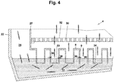
- Fig. 4 Another variant of the steam condenser 4 is shown.
- the channels 9 of the intermediate floor 8 contain different types of openings.
- the openings 33 are designed, for example, as circular holes.
- the openings 34 are configured, for example, as elongated holes or slots.
- the channel 35 can also be open, that is to say have no channel bottom.
- lateral openings 36 can be made in the side walls of the channels 9 to be appropriate. According to this exemplary embodiment, too, the flow cross-sectional area for the steam from the product chamber 7 is dependent on the level of the coolant in the trough 11 of the steam condenser 4.
- the flow cross-section for the steam through the side openings 36 can be increased if the level of the coolant is chosen to be so high is that the side openings are at least partially covered.
- the steam can then enter the coolant through the side openings 36 and the openings at the channel bottom. If the openings are free of coolant, that is to say the level of the coolant is below the lateral openings 36, these openings serve for exchange with adjacent channel spaces. Since the steam can be introduced into the coolant unhindered by these channel spaces, the flow cross-sectional area for the steam increases, that is to say its flow velocity decreases when it passes through the openings of the channels and the channel spaces.
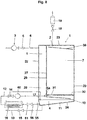
- Fig. 5 shows a variant of the Fig. 1 with heat recovery system.
- the coolant heated up to 60 ° can be passed through a heat exchanger 40 for the waste water cooling.
- the heat exchanger 40 can be arranged in a container 45 through which a fluid can circulate.
- This fluid can comprise a liquid or gaseous heat transfer fluid.
- the container 45 can in particular also be used as a waste water cooler.
- the used coolant which is loaded with impurities, is discharged via the coolant drain line 13 and introduced into the sewage system.
- the coolant Before being discharged into the sewage system, the coolant is cooled by being supplied to the heat exchanger 40. Furthermore, a heat exchanger 41 can be provided, which can be used for preheating a process fluid 43.
- the process fluid 43 to be preheated is passed through a preheater 46, which absorbs the heat of a heat exchange fluid 59 which leaves the heat exchanger 16 via the discharge line 48.
- the heat exchanger 16 for cooling the coolant located in the trough 11 of the steam condenser 4 is fed by the heat exchange fluid 49 via a feed line 47.
- This feed line 47 can either lead directly to the heat exchanger 16 or contain a branch which supplies the vacuum pump 3 with heat exchange fluid.
- the vacuum pump 3 can be cooled by means of the heat exchange fluid 49 if its operating temperature is exceeded.
- the heat exchange fluid 49 which leaves the vacuum pump, can optionally be fed into the feed line 47.
- Shut-off means 57, 58 can be provided in order to couple or decouple the cooling circuit of the vacuum pump 3 with the cooling circuit for the steam condenser 4.
- Fig. 6 shows a variant of the intermediate floor 50.
- the intermediate floor 50 is designed as a flat plate element inclined at an angle to the horizontal plane. This plate element is designed with openings 51, which allow the steam to pass from the product chamber 7 into the separation chamber 28.
- the intermediate floor 50 is at least partially immersed in the coolant located in the steam condenser.
- the flow cross section for the steam through the openings 51 can be increased if the level of the coolant rises, so that a larger part of the openings 51 are at least partially covered. The steam can then enter the coolant through the openings in the intermediate floor 50 above the level of the coolant.
- the openings are free of coolant, that is to say the level of the coolant lies below the openings 51, these openings serve to exchange the vapor space located on the underside of the intermediate floor. Since the steam can be introduced unhindered into the coolant from this steam space, the flow cross-sectional area for the steam increases, that is to say its flow velocity decreases as it passes through the openings in the intermediate floor 50 and the steam space. Accordingly, according to this exemplary embodiment, it is possible to consciously vary the level of the coolant in order to change the flow rate of the steam and therefore also the pressure loss. Therefore, by regulating the level of the coolant Pressure curve and thus the cooling behavior of the food can be influenced.
- FIG. 7 Another variant of the steam condenser 4 is shown.
- the channels 9 of the intermediate floor 8 are designed as tubular elements. These tubular elements can contain different types of openings.
- the openings 33 are designed, for example, as circular holes.
- the openings 34 are configured, for example, as elongated holes or slots.
- the channel can also be open, that is to say have no channel floor, which is not shown in the drawing.
- lateral openings 36 can be provided in the side walls of the channels 9. According to this exemplary embodiment, too, the flow cross-sectional area for the steam from the product chamber 7 is dependent on the level of the coolant in the trough 11 of the steam condenser 4.
- the flow cross-section for the steam through the side openings 36 can be increased if the level of the coolant is chosen to be so high is that the side openings are at least partially covered.
- the steam can then enter the coolant through the side openings 36 and the openings at the channel bottom. If the openings are free of coolant, that is to say the level of the coolant is below the lateral openings 36, these openings serve for exchange with adjacent channel spaces. Since the steam can be introduced into the coolant unhindered by these channel spaces, the flow cross-sectional area for the steam increases, that is to say its flow velocity decreases when it passes through the openings of the channels and the channel spaces.
- the vacuum cooling device 1 shown comprises a vacuum chamber 2, a vacuum source 3 and a steam condenser 4.
- the vacuum source 3 is a vacuum pump which is in fluid-conducting connection with the vacuum chamber 2 via a vacuum line 6.
- a valve 5 is arranged in the vacuum line 6.
- the vacuum chamber 2 contains a product chamber 7, which in the operating state contains the food to be cooled.
- the vacuum cooling device 1 contains a separation chamber 28.
- the separation chamber 28 is arranged next to the product chamber 7 and is separated from the product chamber by an intermediate wall 27.
- the vacuum chamber has in the region of the wall 21 or the wall 25 or the wall 26 a door, not shown, which is opened in order to place the food in the product chamber 7 and to remove it again from the product chamber 7 after the vacuum cooling has been completed.
- the product chamber 7 can be ventilated by means of a ventilation valve 18 which is arranged above the ceiling 23.
- the ventilation valve is connected to the product chamber 7 via a ventilation line.
- a filter element 19 is arranged in the ventilation line in order to filter out impurities from the fresh air, which can impair the quality of the food.
- the ventilation valve can be designed as a variable throttle element. It can be at least partially open during the cooling process.
- the ventilation valve is in the open state, so that an adequate supply of fresh air is ensured for people who are in the product chamber, even if the door of the vacuum chamber 2 is closed. Since moisture enters the product chamber together with the fresh air, the fresh air within the product chamber is deflected via a deflection element 38 in the direction of at least one of the walls 21, 25, 26, 27.
- the wall 26 is in Fig. 8 not visible since it lies in front of the plane of the drawing and the wall 25 forms the rear boundary of the product chamber 7.
- the two walls 25, 26 are in the Fig. 2 shown.
- the deflecting element can be equipped with drainage channels or it ends at its lowest point at a point from which the condensate directly to the chamber floor can drip. These measures can prevent the condensate from coming into contact with the food.
- the vacuum chamber 2 contains the steam condenser 4, which forms the bottom of the product chamber 7.
- the steam condenser 4 is separated from the product chamber 7 by the chamber floor 30.
- the chamber floor 30 therefore serves as a support for a rack trolley which carries the frames which form the support surfaces for the food.
- a channel floor 10 which is designed as a trough 11 filled with liquid.
- the liquid is a coolant which enters the tub 11 via the coolant supply line 12 and can at least partially leave the tub via a coolant drain line 13. Water is usually used as the coolant.
- a coolant valve 14 can be arranged in the coolant supply line 12, but this coolant valve is not necessarily provided. According to the present exemplary embodiment, the coolant is guided in a coolant circuit.
- the coolant circuit contains a heat exchanger which can be arranged in the tub 11 or outside the tub 11, for example in the separating chamber 28 or even outside the vacuum cooling device 1. Heat is extracted from the coolant by means of the heat exchanger 16. This heat can be reintroduced at another point in the processing process as part of heat recovery.
- the heat exchanger 16 can for example be designed as a plate heat exchanger.
- a plurality of heat exchangers can also be provided, which can be arranged in the trough 11, the separating chamber 28 or outside the vacuum cooling device 1.
- the chamber floor 30 contains at least one opening 31 through which the steam can enter the interior of the steam condenser 4.
- a coolant drain valve 15 is arranged in the coolant drain line 13.
- the level of the coolant in the tub 11 is controlled by a level control 17 such that there is a distance between the ramp and the liquid surface remains if 7 steam is generated in the product chamber, which must be condensed.
- a liquid flow occurs over the channel floor. This liquid flow is generated by coolant, which reaches the interior of the steam condenser 4 via a coolant inlet connection.
- the channel floor serves as a mass transfer area.
- the steam is introduced into the coolant flow and thus extracted from the air. At the same time, the heat transfer between steam and coolant takes place. Steam is understood here to mean a water vapor / air mixture which is sucked out of the product chamber 7 when a vacuum is applied via the vacuum line 6.
- Coolant and steam are in direct contact with one another, because the steam is transmitted from the opening or openings 31 to the surface of the coolant flow.
- the steam flows through the opening or openings 31 and into the liquid-filled trough 11.
- the water vapor portion condenses. Any impurities in the steam remain in the coolant, which is enriched with impurities.
- the coolant therefore serves as a filter section for the steam.
- the low-vapor air enters the separation chamber 28.
- the coolant enters the steam condenser 4 via the coolant inlet connection 54 below the chamber floor 30.
- the coolant flows along the channel floor 10, which is designed as a ramp and serves as a steam introduction element.
- the steam entering through the opening 31 flows parallel to the coolant along the channel floor 10. In this way, the steam is in direct contact with the coolant.
- a mass transfer takes place over the surface of the coolant flow by absorbing steam from the coolant flow.
- the coolant flow flows like a waterfall from the lower end of the channel floor 10 into the tub 11. This creates a spray layer, which further promotes the mass transfer. This means that a large part of the mass transfer can already have taken place when the circulated coolant from the lower end of the channel bottom enters the coolant located in the trough 11, which coolant collects at the bottom of the vacuum chamber.
- the end of the channel bottom can be immersed in the coolant.
- the coolant is fed via the coolant drain connection 55 into the one coolant outlet 56, which is led to the heat exchanger 16.
- the coolant flows through the heat exchanger and is cooled.
- the coolant passes from the heat exchanger via the coolant supply line 12 to a circulating pump 60 which conveys the coolant to the coolant inlet connection 54.
- the coolant circuit may include at least one shutoff device 61 to interrupt operation of the coolant circuit.
- the shutoff device 61 may also include a throttle valve to regulate the flow through the coolant outlet.
- a coolant valve 14 can also be provided, which can reduce the coolant flow through the heat exchanger or by means of which the flow through the heat exchanger can be slowed down in order to increase the residence time in the heat exchanger or the flow can be increased to increase the residence time in the Reduce heat exchanger.
- the coolant valve 14 and / or the shut-off device By means of the coolant valve 14 and / or the shut-off device, the flow of coolant through the heat exchanger and the circulated coolant volume can be regulated on the basis of a temperature measurement of the coolant or a level measurement of the coolant.
- This condensate drain also serves to periodically remove the contaminants that accumulate in the coolant from the system.
- the low-vapor air is passed through a separating element 29 located in the separating chamber 28.
- the steam flow which moves in the tub 11 in the direction of the separation chamber 28, can form a spray layer on the liquid surface.
- the separating element 29 is used.
- This separating element can be a droplet separator, which comprises, for example, in perforated sheet metal or a knitted fabric or fabric, on which droplets get caught.
- Several of these Separation elements can be arranged one behind the other and / or one above the other.
- the low-vapor air enters the vacuum line 6 and is sucked off via the vacuum pump 3.
- a heat exchanger can be provided in the separating chamber.
- This heat exchanger can be integrated in the coolant circuit.
- the heat exchanger can be used in order to bring about cooling or, if appropriate, further cooling of the coolant by heating the low-vapor air flow entering the vacuum pump 3.
- a cooling coil can be provided in the trough, which comprises finned tubular elements.
- These finned tube elements are advantageously protected from damage by an intermediate floor or by a permanently installed chamber floor 30, which can only be removed for assembly purposes or for maintenance work. If the finned pipe elements are freely accessible, there is a risk that these pipe elements will be entered by cleaning staff, for example during cleaning.
- the finned tube elements usually do not withstand such a load, especially if the fins are designed as thin-walled sheet metal parts.
Landscapes
- Engineering & Computer Science (AREA)
- Life Sciences & Earth Sciences (AREA)
- Chemical & Material Sciences (AREA)
- Food Science & Technology (AREA)
- Mechanical Engineering (AREA)
- General Engineering & Computer Science (AREA)
- Wood Science & Technology (AREA)
- Zoology (AREA)
- Polymers & Plastics (AREA)
- Thermal Sciences (AREA)
- Physics & Mathematics (AREA)
- Chemical Kinetics & Catalysis (AREA)
- Combustion & Propulsion (AREA)
Claims (13)
- Un dispositif de refroidissement sous vide pour refroidir des aliments, en particulier des pâtisseries chaudes, comprenant une chambre à vide (2), une chambre de produit (7) pour recevoir les aliments pour les refroidir, une chambre de séparation (28), une source de vide (3), telle qu'une pompe à vide, qui est connecté à la chambre de séparation (28) et un condenseur de vapeur (4) pour condenser la vapeur générée dans la chambre de produit (7) pendant le processus de refroidissement, en ce que le condenseur de vapeur (4) est disposé sous la chambre de produit (7), en ce que le condenseur de vapeur (4) contient un réfrigérant dans un bac (11) et comprend un élément d'introduction de vapeur (8, 9, 10) pour introduire la vapeur de la chambre de produit (7) dans le réfrigérant, en ce que la chambre de séparation (28) est structurellement séparé de la chambre de produit (7) par une paroi intermédiaire (27), la chambre de séparation (28) étant disposée en amont de la source de vide (3) par rapport au sens d'écoulement de la vapeur, et en ce que l'élément d'introduction de vapeur (8, 9, 10) du condenseur de vapeur (4) est disposé en amont de la chambre de séparation (28), caractérisé en ce que la chambre de séparation (28) est disposée au-dessus du condenseur de vapeur (4).
- Le dispositif de refroidissement sous vide selon la revendication 1, dans lequel l'élément d'introduction de vapeur (8, 9, 10) est disposé sous un fond de chambre (30).
- Le dispositif de refroidissement sous vide selon la revendication 1 ou 2, dans lequel l'élément d'introduction de vapeur (8, 9, 10) comprend une pluralité de canaux ou d'éléments de tuyau (39) ou un élément de plaque (50) qui font partiellement saillie dans le réfrigérant, en ce que le condenseur de vapeur (4) peut être formée comme une partie de la chambre à vide (2), dans laquelle le condenseur de vapeur est conçu en particulier comme une section de filtre pour la rétention des impuretés dans la vapeur.
- Le dispositif de refroidissement sous vide selon l'une des revendications précédentes, dans lequel une unité de contrôle (17) est prévue pour contrôler la quantité de l'eau condensée et / ou de la température de l'eau condensée.
- Le dispositif de refroidissement sous vide selon l'une des revendications précédentes, dans lequel un élément de séparation est disposé dans la chambre de séparation.
- Le dispositif de refroidissement sous vide selon l'une des revendications précédentes, dans lequel la source de vide comprend une pompe à vide, la pompe à vide étant notamment une pompe à vide de vitesse contrôlée.
- Dispositif de refroidissement sous vide selon l'une des revendications précédentes, dans lequel le bac (11) contient un échangeur de chaleur (16) ou un échangeur de chaleur est disposé à l'extérieur du bac (11), en ce que le réfrigérant peut être refroidi au moyen de l'échangeur de chaleur, en ce que le réfrigérant peut être passé à travers l'échangeur de chaleur en circuit fermé.
- Procédé de refroidissement sous vide d'un aliment comprenant les étapes: remplir une chambre de produit (7) d'un dispositif de refroidissement sous vide (1) avec un aliment, fermer la chambre de produit, actionner une source de vide pour générer une pression négative, retirer l'aliment refroidi, en ce que la vapeur générée par le refroidissement des aliments est condensée dans un condenseur de vapeur (4) dans la chambre de produit (7), en ce que le condenseur de vapeur est disposé dans la chambre de produit, en ce que la source de vide (3) est reliée à la chambre de séparation (28), en ce que la chambre de séparation (28) est structurellement séparée de la chambre de produit par une paroi intermédiaire (27), en ce que la chambre de séparation (28) est disposée en amont de la source de vide (3) par rapport à la direction d'écoulement de la vapeur et un élément d'introduction de vapeur (8, 9, 10) du condenseur de vapeur (4) est disposé en amont de la chambre de séparation (28) de telle sorte que la vapeur provenant de la chambre de produit (7) s'écoule à travers de l'élément d'introduction de vapeur (8, 9,10) dans la chambre de séparation (28) vers la source de vide (3), caractérisé en ce que la chambre de séparation (28) est disposée au-dessus du condenseur de vapeur (4).
- Le procédé de refroidissement sous vide d'un aliment selon la revendication 8, dans lequel le condenseur de vapeur contient un réfrigérant dans un bac (11), de sorte que la vapeur est guidée dans l'élément d'introduction de vapeur (8, 9, 10) et est introduite dans le réfrigérant.
- Le procédé de refroidissement sous vide d'un aliment selon la revendication 8 ou 9, dans lequel le réfrigérant est chargé de vapeur et la vapeur contient une proportion d'eau qui condense dans le réfrigérant, en ce que le réfrigérant est notamment de l'eau, en ce qu'en particulier au moins 60%, de préférence au moins 90% de l'eau condense dans la vapeur du condenseur de vapeur (4).
- Le procédé de refroidissement sous vide d'un aliment selon l'une des revendications 8 à 10, dans lequel le réfrigérant est remplacé périodiquement ou parce qu'une valeur limite prédéterminée est atteinte, notamment lorsque sa température devient trop élevée, la concentration des impuretés atteint une valeur maximale ou le pH est tombée à 4 ou moins.
- Le procédé de refroidissement sous vide d'un aliment selon l'une des revendications 8 à 11, dans lequel le refroidissement du réfrigérant est atteint au moyen d'un échangeur de chaleur (16) alimenté, par exemple, en eau douce.
- Le procédé de refroidissement sous vide d'un aliment selon l'une des revendications 8 à 12, dans lequel les impuretés dans la vapeur sont enrichies dans le condensat et sont évacuées avec le condensat.
Priority Applications (1)
| Application Number | Priority Date | Filing Date | Title |
|---|---|---|---|
| EP14179208.5A EP2832241B1 (fr) | 2013-08-01 | 2014-07-30 | Dispositif et procédé de condensation de vapeur dans une chambre à vide |
Applications Claiming Priority (2)
| Application Number | Priority Date | Filing Date | Title |
|---|---|---|---|
| EP13178986 | 2013-08-01 | ||
| EP14179208.5A EP2832241B1 (fr) | 2013-08-01 | 2014-07-30 | Dispositif et procédé de condensation de vapeur dans une chambre à vide |
Publications (2)
| Publication Number | Publication Date |
|---|---|
| EP2832241A1 EP2832241A1 (fr) | 2015-02-04 |
| EP2832241B1 true EP2832241B1 (fr) | 2020-05-06 |
Family
ID=48900880
Family Applications (1)
| Application Number | Title | Priority Date | Filing Date |
|---|---|---|---|
| EP14179208.5A Active EP2832241B1 (fr) | 2013-08-01 | 2014-07-30 | Dispositif et procédé de condensation de vapeur dans une chambre à vide |
Country Status (3)
| Country | Link |
|---|---|
| US (1) | US9668490B2 (fr) |
| EP (1) | EP2832241B1 (fr) |
| AU (1) | AU2014206166A1 (fr) |
Families Citing this family (8)
| Publication number | Priority date | Publication date | Assignee | Title |
|---|---|---|---|---|
| EP2362168A1 (fr) * | 2010-01-27 | 2011-08-31 | Revent International AB | Système et procédé pour le refroidissement du pain et la récupération de la chaleur émise |
| WO2017040217A1 (fr) * | 2015-08-28 | 2017-03-09 | Miyoshi Mark | Système de refroidissement par immersion à faible perte de fluide |
| CH711722A2 (de) | 2015-11-04 | 2017-05-15 | Giger Ulrich | Vakuumkühlvorrichtung und Verfahren zur Vakuumkühlung von Lebensmitteln. |
| IT201600096779A1 (it) * | 2016-09-27 | 2018-03-27 | Iteca Impianti Tecnologici Alimentari Speciali S P A | Apparato per il raffreddamento di prodotti alimentari da forno, nonche’ stazione di raffreddamento ed impianto che includono tale apparato |
| CN116324283B (zh) * | 2020-10-09 | 2026-03-31 | 沃克豪斯股份两合公司 | 用于处理蒸汽的装置 |
| CN113776272A (zh) * | 2021-09-16 | 2021-12-10 | 赖仕红 | 一种钢管冷却系统 |
| CN117137165B (zh) * | 2023-07-03 | 2025-10-03 | 福建中烟工业有限责任公司 | 烘丝机凝结水收集系统 |
| CN221915492U (zh) * | 2023-12-29 | 2024-10-29 | 深圳市有盛电器有限公司 | 罐口密封装置 |
Citations (1)
| Publication number | Priority date | Publication date | Assignee | Title |
|---|---|---|---|---|
| JP2000193369A (ja) * | 1998-12-24 | 2000-07-14 | Paloma Ind Ltd | 厨芥処理機 |
Family Cites Families (21)
| Publication number | Priority date | Publication date | Assignee | Title |
|---|---|---|---|---|
| US996991A (en) | 1909-06-11 | 1911-07-04 | Cleaning Devices Mfg Company | Vacuum apparatus. |
| US2072737A (en) | 1935-06-17 | 1937-03-02 | Montague H Duval | Process of cooling bread and bakery products |
| US2696775A (en) | 1950-08-23 | 1954-12-14 | Foster Wheeler Corp | Cooking and refrigerating apparatus |
| DE1017593B (de) | 1953-02-05 | 1957-10-17 | A Olier Sa Des Ets | Oberflaechenkondensator fuer Vakuumbetrieb |
| GB1413481A (en) | 1972-01-14 | 1975-11-12 | Tweedy Of Burnley Ltd | Treatment of foodstuffs |
| GB1516654A (en) * | 1974-08-26 | 1978-07-05 | Grumman Allied Industries | Low temperature hypobaric storage of metabolically active matter |
| DE2902270C2 (de) | 1979-01-22 | 1982-11-11 | Fr. Winkler KG Spezialfabrik für Bäckereimaschinen und Backöfen, 7730 Villingen-Schwenningen | Verfahren zum Abkühlen von Backgut |
| US4229886A (en) * | 1979-03-09 | 1980-10-28 | Mcdonnell Douglas Corporation | Microwave heated vacuum dryer for powders |
| AT400279B (de) | 1992-02-20 | 1995-11-27 | Sorger Albin | Verfahren und einrichtung zur erzeugung bzw. konservierung von vorgebackenen backwaren |
| US5235903A (en) | 1992-03-17 | 1993-08-17 | Tippmann Eugene R | Subatmospheric pressure cook-and-hold steaming oven |
| EP0686400A1 (fr) | 1994-06-10 | 1995-12-13 | C. STIEFENHOFER GmbH | Stérilisateur à vapeur avec récupération de chaleur |
| WO1997032113A1 (fr) | 1994-08-29 | 1997-09-04 | Ranotor Utvecklings Ab | Installation de type moteur a vapeur comprenant un systeme de condenseur |
| US5946919A (en) | 1997-05-02 | 1999-09-07 | Sharper Image Corp. | Food conservator system |
| US6148875A (en) * | 1997-06-18 | 2000-11-21 | Breen; James | Vacuum food storage system |
| JPH11211314A (ja) | 1998-01-29 | 1999-08-06 | Samson Co Ltd | 真空冷却機用のチラー運転制御装置 |
| JP2001221546A (ja) | 2000-02-14 | 2001-08-17 | Samson Co Ltd | 真空冷却装置の熱交換器洗浄方法 |
| JP4827009B2 (ja) | 2006-01-19 | 2011-11-30 | 三浦工業株式会社 | 複合冷却装置 |
| DE102008035068B4 (de) | 2008-07-26 | 2011-02-17 | Lsg Lufthansa Service Holding Ag | Verfahren zur Verlängerung der Krusten-Rösche |
| JP2010133569A (ja) | 2008-12-02 | 2010-06-17 | Miura Co Ltd | 複合冷却装置 |
| US8661838B2 (en) * | 2010-06-07 | 2014-03-04 | Flsmidth A/S | Central vacuum cooling plant |
| SE535844C2 (sv) | 2010-12-16 | 2013-01-08 | Revent Int Ab | Anordning och metod för återfuktning av ätbara produkter |
-
2014
- 2014-07-24 AU AU2014206166A patent/AU2014206166A1/en not_active Abandoned
- 2014-07-25 US US14/341,342 patent/US9668490B2/en active Active
- 2014-07-30 EP EP14179208.5A patent/EP2832241B1/fr active Active
Patent Citations (1)
| Publication number | Priority date | Publication date | Assignee | Title |
|---|---|---|---|---|
| JP2000193369A (ja) * | 1998-12-24 | 2000-07-14 | Paloma Ind Ltd | 厨芥処理機 |
Also Published As
| Publication number | Publication date |
|---|---|
| US9668490B2 (en) | 2017-06-06 |
| AU2014206166A1 (en) | 2015-02-19 |
| US20150037483A1 (en) | 2015-02-05 |
| EP2832241A1 (fr) | 2015-02-04 |
Similar Documents
| Publication | Publication Date | Title |
|---|---|---|
| EP2832241A1 (fr) | Dispositif et procédé de condensation de vapeur dans une chambre à vide | |
| EP2254422B1 (fr) | Appareil de cuisson équipé d'un dispositif de condensation des vapeurs | |
| DE112015005248B4 (de) | Wärmebehandlungsvorrichtung und kühlvorrichtung | |
| EP3423765B1 (fr) | Pompe à chaleur pourvue d'une chambre de collecte de gaz étranger, procédé pour faire fonctionner une pompe à chaleur et procédé de fabrication d'une pompe à chaleur | |
| EP2832242B1 (fr) | Procédé de réglage d'un dispositif de refroidissement sous vide | |
| EP3165859B1 (fr) | Dispositif de refroidissement à vide et procédé pour le refroidissement à vide des aliments | |
| DE2717543B2 (de) | Verfahren zum Destillieren einer Flüssigkeit und Vorrichtung zur Durchführung des Verfahrens | |
| DE3513021A1 (de) | Verfahren und vorrichtung zum waermebehandeln von fliessfaehigen materialien | |
| DE102009048062B4 (de) | Wärmeträgerölanlage sowie Verfahren zum Betreiben einer Wärmeträgerölanlage | |
| CH710735A1 (de) | Mehrstufige Destillationsanlage, Verfahren zum Betreiben einer solchen und Steuerung dafür. | |
| EP2635358A1 (fr) | Procédé basé sur les micro-ondes et dispositif pour la production de liquides de haute pureté | |
| CH708608A2 (de) | Verfahren zur Auswahl eines Kühlprogramms zur Kühlung von Lebensmitteln in einer Vakuumkühlvorrichtung. | |
| WO2021110187A1 (fr) | Procédé et installation de distillation d'un liquide | |
| EP1248060A1 (fr) | Dispositif de séchage d'une isolation solide d'un appareil électrique | |
| EP3029403B1 (fr) | Procédé et dispositif de séchage de l'isolation de matière solide de la pièce active d'un appareil électrique selon le procédé de phase gazeuse | |
| DE102014101298B4 (de) | Verfahren und Vorrichtung zum Aufheizen, Reinigen und Trocknen von Trocknungsgütern | |
| DE202012010739U1 (de) | Reinigungsanlage für Reinigungsverfahren mit einer Reinigungsflüssigkeit und einem Hydro-Fluor-Ether | |
| DE102024108012A1 (de) | Verfahren zum thermischen Behandeln eines Produkts mittels Dampfs in einem Autoklav mit Kondensatabführung | |
| DE3504400C2 (fr) | ||
| DE1551291C3 (de) | Absorptions-Kälteanlage | |
| DE459046C (de) | Verfahren zur Entfernung von Luft aus dem Kaeltemittelkreislauf in Kuehlsystemen | |
| DE19901169C2 (de) | Vorrichtung zur Rückgewinnung des Lösungsmittels aus dem Restschlamm von Einrichtungen zur chemischen Reinigung insbesondere von Textilien oder Metallteilen | |
| DE102023130573A1 (de) | Geschirrspülmaschine mit wärmepumpenvorrichtung und ansaugvorrichtung für maschinenluft und umgebungsluft | |
| EP2996823A1 (fr) | Installation de nettoyage d'éléments | |
| DE1551291B2 (de) | Absorptions-kaelteanlage |
Legal Events
| Date | Code | Title | Description |
|---|---|---|---|
| 17P | Request for examination filed |
Effective date: 20140730 |
|
| AK | Designated contracting states |
Kind code of ref document: A1 Designated state(s): AL AT BE BG CH CY CZ DE DK EE ES FI FR GB GR HR HU IE IS IT LI LT LU LV MC MK MT NL NO PL PT RO RS SE SI SK SM TR |
|
| AX | Request for extension of the european patent |
Extension state: BA ME |
|
| PUAI | Public reference made under article 153(3) epc to a published international application that has entered the european phase |
Free format text: ORIGINAL CODE: 0009012 |
|
| R17P | Request for examination filed (corrected) |
Effective date: 20150804 |
|
| RBV | Designated contracting states (corrected) |
Designated state(s): AL AT BE BG CH CY CZ DE DK EE ES FI FR GB GR HR HU IE IS IT LI LT LU LV MC MK MT NL NO PL PT RO RS SE SI SK SM TR |
|
| STAA | Information on the status of an ep patent application or granted ep patent |
Free format text: STATUS: EXAMINATION IS IN PROGRESS |
|
| 17Q | First examination report despatched |
Effective date: 20180424 |
|
| RAP1 | Party data changed (applicant data changed or rights of an application transferred) |
Owner name: GIGER, ULRICH Owner name: BAEBLER, FLORIAN Owner name: BAEBLER, KASPAR |
|
| RIN1 | Information on inventor provided before grant (corrected) |
Inventor name: GIGER, ULRICH Inventor name: BAEBLER, FLORIAN Inventor name: BAEBLER, KASPAR |
|
| GRAP | Despatch of communication of intention to grant a patent |
Free format text: ORIGINAL CODE: EPIDOSNIGR1 |
|
| STAA | Information on the status of an ep patent application or granted ep patent |
Free format text: STATUS: GRANT OF PATENT IS INTENDED |
|
| GRAS | Grant fee paid |
Free format text: ORIGINAL CODE: EPIDOSNIGR3 |
|
| INTG | Intention to grant announced |
Effective date: 20200306 |
|
| GRAA | (expected) grant |
Free format text: ORIGINAL CODE: 0009210 |
|
| STAA | Information on the status of an ep patent application or granted ep patent |
Free format text: STATUS: THE PATENT HAS BEEN GRANTED |
|
| AK | Designated contracting states |
Kind code of ref document: B1 Designated state(s): AL AT BE BG CH CY CZ DE DK EE ES FI FR GB GR HR HU IE IS IT LI LT LU LV MC MK MT NL NO PL PT RO RS SE SI SK SM TR |
|
| RAP1 | Party data changed (applicant data changed or rights of an application transferred) |
Owner name: GLAVATEC AG |
|
| REG | Reference to a national code |
Ref country code: GB Ref legal event code: FG4D Free format text: NOT ENGLISH |
|
| RIN1 | Information on inventor provided before grant (corrected) |
Inventor name: BAEBLER, FLORIAN Inventor name: BAEBLER, KASPAR Inventor name: GIGER, ULRICH |
|
| REG | Reference to a national code |
Ref country code: CH Ref legal event code: EP Ref country code: CH Ref legal event code: NV Representative=s name: INDUSTRIAL PROPERTY SERVICES GMBH, CH Ref country code: AT Ref legal event code: REF Ref document number: 1265372 Country of ref document: AT Kind code of ref document: T Effective date: 20200515 |
|
| REG | Reference to a national code |
Ref country code: IE Ref legal event code: FG4D Free format text: LANGUAGE OF EP DOCUMENT: GERMAN |
|
| REG | Reference to a national code |
Ref country code: DE Ref legal event code: R096 Ref document number: 502014014119 Country of ref document: DE |
|
| REG | Reference to a national code |
Ref country code: NL Ref legal event code: FP |
|
| REG | Reference to a national code |
Ref country code: LT Ref legal event code: MG4D |
|
| PG25 | Lapsed in a contracting state [announced via postgrant information from national office to epo] |
Ref country code: FI Free format text: LAPSE BECAUSE OF FAILURE TO SUBMIT A TRANSLATION OF THE DESCRIPTION OR TO PAY THE FEE WITHIN THE PRESCRIBED TIME-LIMIT Effective date: 20200506 Ref country code: GR Free format text: LAPSE BECAUSE OF FAILURE TO SUBMIT A TRANSLATION OF THE DESCRIPTION OR TO PAY THE FEE WITHIN THE PRESCRIBED TIME-LIMIT Effective date: 20200807 Ref country code: NO Free format text: LAPSE BECAUSE OF FAILURE TO SUBMIT A TRANSLATION OF THE DESCRIPTION OR TO PAY THE FEE WITHIN THE PRESCRIBED TIME-LIMIT Effective date: 20200806 Ref country code: LT Free format text: LAPSE BECAUSE OF FAILURE TO SUBMIT A TRANSLATION OF THE DESCRIPTION OR TO PAY THE FEE WITHIN THE PRESCRIBED TIME-LIMIT Effective date: 20200506 Ref country code: IS Free format text: LAPSE BECAUSE OF FAILURE TO SUBMIT A TRANSLATION OF THE DESCRIPTION OR TO PAY THE FEE WITHIN THE PRESCRIBED TIME-LIMIT Effective date: 20200906 Ref country code: PT Free format text: LAPSE BECAUSE OF FAILURE TO SUBMIT A TRANSLATION OF THE DESCRIPTION OR TO PAY THE FEE WITHIN THE PRESCRIBED TIME-LIMIT Effective date: 20200907 Ref country code: SE Free format text: LAPSE BECAUSE OF FAILURE TO SUBMIT A TRANSLATION OF THE DESCRIPTION OR TO PAY THE FEE WITHIN THE PRESCRIBED TIME-LIMIT Effective date: 20200506 |
|
| PG25 | Lapsed in a contracting state [announced via postgrant information from national office to epo] |
Ref country code: HR Free format text: LAPSE BECAUSE OF FAILURE TO SUBMIT A TRANSLATION OF THE DESCRIPTION OR TO PAY THE FEE WITHIN THE PRESCRIBED TIME-LIMIT Effective date: 20200506 Ref country code: BG Free format text: LAPSE BECAUSE OF FAILURE TO SUBMIT A TRANSLATION OF THE DESCRIPTION OR TO PAY THE FEE WITHIN THE PRESCRIBED TIME-LIMIT Effective date: 20200806 Ref country code: LV Free format text: LAPSE BECAUSE OF FAILURE TO SUBMIT A TRANSLATION OF THE DESCRIPTION OR TO PAY THE FEE WITHIN THE PRESCRIBED TIME-LIMIT Effective date: 20200506 Ref country code: RS Free format text: LAPSE BECAUSE OF FAILURE TO SUBMIT A TRANSLATION OF THE DESCRIPTION OR TO PAY THE FEE WITHIN THE PRESCRIBED TIME-LIMIT Effective date: 20200506 |
|
| PG25 | Lapsed in a contracting state [announced via postgrant information from national office to epo] |
Ref country code: AL Free format text: LAPSE BECAUSE OF FAILURE TO SUBMIT A TRANSLATION OF THE DESCRIPTION OR TO PAY THE FEE WITHIN THE PRESCRIBED TIME-LIMIT Effective date: 20200506 |
|
| PG25 | Lapsed in a contracting state [announced via postgrant information from national office to epo] |
Ref country code: ES Free format text: LAPSE BECAUSE OF FAILURE TO SUBMIT A TRANSLATION OF THE DESCRIPTION OR TO PAY THE FEE WITHIN THE PRESCRIBED TIME-LIMIT Effective date: 20200506 Ref country code: CZ Free format text: LAPSE BECAUSE OF FAILURE TO SUBMIT A TRANSLATION OF THE DESCRIPTION OR TO PAY THE FEE WITHIN THE PRESCRIBED TIME-LIMIT Effective date: 20200506 Ref country code: RO Free format text: LAPSE BECAUSE OF FAILURE TO SUBMIT A TRANSLATION OF THE DESCRIPTION OR TO PAY THE FEE WITHIN THE PRESCRIBED TIME-LIMIT Effective date: 20200506 Ref country code: SM Free format text: LAPSE BECAUSE OF FAILURE TO SUBMIT A TRANSLATION OF THE DESCRIPTION OR TO PAY THE FEE WITHIN THE PRESCRIBED TIME-LIMIT Effective date: 20200506 Ref country code: IT Free format text: LAPSE BECAUSE OF FAILURE TO SUBMIT A TRANSLATION OF THE DESCRIPTION OR TO PAY THE FEE WITHIN THE PRESCRIBED TIME-LIMIT Effective date: 20200506 Ref country code: EE Free format text: LAPSE BECAUSE OF FAILURE TO SUBMIT A TRANSLATION OF THE DESCRIPTION OR TO PAY THE FEE WITHIN THE PRESCRIBED TIME-LIMIT Effective date: 20200506 Ref country code: DK Free format text: LAPSE BECAUSE OF FAILURE TO SUBMIT A TRANSLATION OF THE DESCRIPTION OR TO PAY THE FEE WITHIN THE PRESCRIBED TIME-LIMIT Effective date: 20200506 |
|
| REG | Reference to a national code |
Ref country code: DE Ref legal event code: R097 Ref document number: 502014014119 Country of ref document: DE |
|
| PG25 | Lapsed in a contracting state [announced via postgrant information from national office to epo] |
Ref country code: MC Free format text: LAPSE BECAUSE OF FAILURE TO SUBMIT A TRANSLATION OF THE DESCRIPTION OR TO PAY THE FEE WITHIN THE PRESCRIBED TIME-LIMIT Effective date: 20200506 Ref country code: SK Free format text: LAPSE BECAUSE OF FAILURE TO SUBMIT A TRANSLATION OF THE DESCRIPTION OR TO PAY THE FEE WITHIN THE PRESCRIBED TIME-LIMIT Effective date: 20200506 Ref country code: PL Free format text: LAPSE BECAUSE OF FAILURE TO SUBMIT A TRANSLATION OF THE DESCRIPTION OR TO PAY THE FEE WITHIN THE PRESCRIBED TIME-LIMIT Effective date: 20200506 |
|
| PLBE | No opposition filed within time limit |
Free format text: ORIGINAL CODE: 0009261 |
|
| STAA | Information on the status of an ep patent application or granted ep patent |
Free format text: STATUS: NO OPPOSITION FILED WITHIN TIME LIMIT |
|
| 26N | No opposition filed |
Effective date: 20210209 |
|
| REG | Reference to a national code |
Ref country code: BE Ref legal event code: MM Effective date: 20200731 |
|
| PG25 | Lapsed in a contracting state [announced via postgrant information from national office to epo] |
Ref country code: LU Free format text: LAPSE BECAUSE OF NON-PAYMENT OF DUE FEES Effective date: 20200730 |
|
| PG25 | Lapsed in a contracting state [announced via postgrant information from national office to epo] |
Ref country code: BE Free format text: LAPSE BECAUSE OF NON-PAYMENT OF DUE FEES Effective date: 20200731 Ref country code: SI Free format text: LAPSE BECAUSE OF FAILURE TO SUBMIT A TRANSLATION OF THE DESCRIPTION OR TO PAY THE FEE WITHIN THE PRESCRIBED TIME-LIMIT Effective date: 20200506 |
|
| PG25 | Lapsed in a contracting state [announced via postgrant information from national office to epo] |
Ref country code: IE Free format text: LAPSE BECAUSE OF NON-PAYMENT OF DUE FEES Effective date: 20200730 |
|
| PG25 | Lapsed in a contracting state [announced via postgrant information from national office to epo] |
Ref country code: TR Free format text: LAPSE BECAUSE OF FAILURE TO SUBMIT A TRANSLATION OF THE DESCRIPTION OR TO PAY THE FEE WITHIN THE PRESCRIBED TIME-LIMIT Effective date: 20200506 Ref country code: MT Free format text: LAPSE BECAUSE OF FAILURE TO SUBMIT A TRANSLATION OF THE DESCRIPTION OR TO PAY THE FEE WITHIN THE PRESCRIBED TIME-LIMIT Effective date: 20200506 Ref country code: CY Free format text: LAPSE BECAUSE OF FAILURE TO SUBMIT A TRANSLATION OF THE DESCRIPTION OR TO PAY THE FEE WITHIN THE PRESCRIBED TIME-LIMIT Effective date: 20200506 |
|
| PG25 | Lapsed in a contracting state [announced via postgrant information from national office to epo] |
Ref country code: MK Free format text: LAPSE BECAUSE OF FAILURE TO SUBMIT A TRANSLATION OF THE DESCRIPTION OR TO PAY THE FEE WITHIN THE PRESCRIBED TIME-LIMIT Effective date: 20200506 |
|
| P01 | Opt-out of the competence of the unified patent court (upc) registered |
Effective date: 20230427 |
|
| REG | Reference to a national code |
Ref country code: DE Ref legal event code: R079 Ref document number: 502014014119 Country of ref document: DE Free format text: PREVIOUS MAIN CLASS: A23L0003360000 Ipc: A23B0002800000 |
|
| PGFP | Annual fee paid to national office [announced via postgrant information from national office to epo] |
Ref country code: NL Payment date: 20250702 Year of fee payment: 12 |
|
| PGFP | Annual fee paid to national office [announced via postgrant information from national office to epo] |
Ref country code: DE Payment date: 20250731 Year of fee payment: 12 |
|
| PGFP | Annual fee paid to national office [announced via postgrant information from national office to epo] |
Ref country code: GB Payment date: 20250714 Year of fee payment: 12 |
|
| PGFP | Annual fee paid to national office [announced via postgrant information from national office to epo] |
Ref country code: FR Payment date: 20250702 Year of fee payment: 12 Ref country code: AT Payment date: 20250702 Year of fee payment: 12 |
|
| PGFP | Annual fee paid to national office [announced via postgrant information from national office to epo] |
Ref country code: CH Payment date: 20250801 Year of fee payment: 12 |