EP2832507B1 - Procédé destiné et scie à panneaux horizontale au sciage de pièces à usiner - Google Patents
Procédé destiné et scie à panneaux horizontale au sciage de pièces à usiner Download PDFInfo
- Publication number
- EP2832507B1 EP2832507B1 EP13003773.2A EP13003773A EP2832507B1 EP 2832507 B1 EP2832507 B1 EP 2832507B1 EP 13003773 A EP13003773 A EP 13003773A EP 2832507 B1 EP2832507 B1 EP 2832507B1
- Authority
- EP
- European Patent Office
- Prior art keywords
- workpiece
- sawing
- workpiece parts
- support table
- work region
- Prior art date
- Legal status (The legal status is an assumption and is not a legal conclusion. Google has not performed a legal analysis and makes no representation as to the accuracy of the status listed.)
- Active
Links
Images


Classifications
-
- B—PERFORMING OPERATIONS; TRANSPORTING
- B27—WORKING OR PRESERVING WOOD OR SIMILAR MATERIAL; NAILING OR STAPLING MACHINES IN GENERAL
- B27B—SAWS FOR WOOD OR SIMILAR MATERIAL; COMPONENTS OR ACCESSORIES THEREFOR
- B27B27/00—Guide fences or stops for timber in saw mills or sawing machines; Measuring equipment thereon
- B27B27/04—Guide fences or stops for timber in saw mills or sawing machines; Measuring equipment thereon arranged perpendicularly to the plane of the saw blade
-
- B—PERFORMING OPERATIONS; TRANSPORTING
- B27—WORKING OR PRESERVING WOOD OR SIMILAR MATERIAL; NAILING OR STAPLING MACHINES IN GENERAL
- B27B—SAWS FOR WOOD OR SIMILAR MATERIAL; COMPONENTS OR ACCESSORIES THEREFOR
- B27B31/00—Arrangements for conveying, loading, turning, adjusting, or discharging the log or timber, specially designed for saw mills or sawing machines
-
- B—PERFORMING OPERATIONS; TRANSPORTING
- B27—WORKING OR PRESERVING WOOD OR SIMILAR MATERIAL; NAILING OR STAPLING MACHINES IN GENERAL
- B27B—SAWS FOR WOOD OR SIMILAR MATERIAL; COMPONENTS OR ACCESSORIES THEREFOR
- B27B5/00—Sawing machines working with circular or cylindrical saw blades; Components or equipment therefor
- B27B5/02—Sawing machines working with circular or cylindrical saw blades; Components or equipment therefor characterised by a special purpose only
- B27B5/06—Sawing machines working with circular or cylindrical saw blades; Components or equipment therefor characterised by a special purpose only for dividing plates in parts of determined size, e.g. panels
- B27B5/065—Sawing machines working with circular or cylindrical saw blades; Components or equipment therefor characterised by a special purpose only for dividing plates in parts of determined size, e.g. panels with feedable saw blades, e.g. arranged on a carriage
-
- B—PERFORMING OPERATIONS; TRANSPORTING
- B23—MACHINE TOOLS; METAL-WORKING NOT OTHERWISE PROVIDED FOR
- B23D—PLANING; SLOTTING; SHEARING; BROACHING; SAWING; FILING; SCRAPING; LIKE OPERATIONS FOR WORKING METAL BY REMOVING MATERIAL, NOT OTHERWISE PROVIDED FOR
- B23D47/00—Sawing machines or sawing devices working with circular saw blades, characterised only by constructional features of particular parts
- B23D47/02—Sawing machines or sawing devices working with circular saw blades, characterised only by constructional features of particular parts of frames; of guiding arrangements for work-table or saw-carrier
- B23D47/025—Sawing machines or sawing devices working with circular saw blades, characterised only by constructional features of particular parts of frames; of guiding arrangements for work-table or saw-carrier of tables
-
- B—PERFORMING OPERATIONS; TRANSPORTING
- B27—WORKING OR PRESERVING WOOD OR SIMILAR MATERIAL; NAILING OR STAPLING MACHINES IN GENERAL
- B27B—SAWS FOR WOOD OR SIMILAR MATERIAL; COMPONENTS OR ACCESSORIES THEREFOR
- B27B31/00—Arrangements for conveying, loading, turning, adjusting, or discharging the log or timber, specially designed for saw mills or sawing machines
- B27B31/08—Discharging equipment
Definitions
- the present invention relates to a method for sawing at least one workpiece consisting of a plate or a stack of plates with a plate dividing system, the workpiece lying on a support table of the plate dividing system for sawing in a feed direction from a sawing line arranged in front of a sawing line of the plate dividing system , the first work area of the support table is fed to the saw line and is sawn into at least two workpiece parts along the saw line by means of at least one saw device of the plate dividing system, and at least one of the workpiece parts across the saw line into a second work area, arranged in the feed direction, behind the saw line of the plate division system Support table is transported.
- a method according to the preamble of claim 1 and a plate dividing system according to the preamble of claim 13 are known from DE 10 2010 010 746 A1 .
- Plate dividing systems are e.g. used in furniture manufacturing to saw workpieces, which consist of plates or plate stacks, until they are divided into workpiece parts or blanks, which then correspond to the final desired size.
- workpieces which consist of plates or plate stacks
- workpiece parts or blanks which then correspond to the final desired size.
- a generic method is for example in the DE 10 2010 010 746 A1 shown.
- the workpiece is transported in the feed direction by means of a feed device which is guided on rails arranged parallel to the feed direction.
- the similar shows EP 2 147 760 A2 .
- EP 1 854 600 A1 are, seen in the feed direction, stop rails in front of and behind the saw line.
- the object of the invention is to improve a generic method in such a way that even complex sawing plans can be processed simply and quickly effectively with a comparatively simple panel sizing system.
- the invention proposes that the first work area and / or the second work area be or are limited in a transverse direction orthogonal to the feed direction by two opposing stop rails and that at least one of the workpiece parts is conveyed to one of the stop rails, while at least another the workpiece parts (9) on the other stop rail (12, 13) adjacent to the saw line (6) are sawn further.
- the aforementioned transport is faster than the sawing, since it is then ensured that the sawing operations can be carried out as quickly as possible one after the other and the sawing device in order to process the Sawing schedule can be used in a time-optimized manner.
- the wording with "while” thus means that the said conveying of the at least one workpiece part overlaps at least in time with the sawing of the at least one other workpiece part.
- the stop rails can laterally limit only the first working area or only the second working area or both working areas in the transverse direction. Arrangements of the stop rails that are axisymmetric with respect to an axis of symmetry parallel to the feed direction are preferred. However, a diagonal type of arrangement of the stop rails can also be selected, e.g. in that one stop rail delimits the first work area on one side and a second, opposite stop rail delimits the second work area on the opposite side. All of these are possible embodiments of the invention.
- this is the direction in which the workpiece or the workpiece parts are generally fed directly to the saw line directly before or during the sawing process.
- this does not necessarily mean that the workpiece e.g. the raw plate or the raw plate stack, before starting the method according to the invention, not also once against the feed direction, e.g. manually or by means of the feed device mentioned below, can be inserted or drawn into the first working area.
- the exact alignment of the workpiece part or the workpiece parts by pressing flat against the stop rail in preparation for the next sawing process can also be carried out separately, for example, only immediately before the at least one workpiece part is sawn further.
- the workpiece and / or at least one of the workpiece parts, preferably immediately before sawing and / or lowering the pressure beam, by at least one aligner, preferably the plate dividing system, for alignment in a Transverse direction is pressed against one of the stop rails.
- the aligner (s) is or are advantageously arranged as close as possible to the saw line.
- Aligners can also be integrated into the support table as pegs or cams, which can be moved in particular in the transverse direction, preferably can be raised and lowered.
- Particularly preferred embodiments of the invention provide that, in successive method steps, at least one of the workpiece parts is alternately conveyed to one of the stop rails in one of the method steps, while at least another of the workpiece parts adjacent to the other stop rail is sawn further and in one Process step carried out later is sawing at least one of the workpiece parts against one of the stop rails further along the saw line, while at least another of the workpiece parts is conveyed towards the other stop rail.
- a preferred alternating procedure is thus proposed, in which at least one workpiece is conveyed to one of the stop rails on one side and is thus pre-positioned for the next sawing process, while at least one other workpiece part is further sawn against the other stop rail. If all sawing operations carried out on this workpiece part or these workpiece parts in this method step have been carried out, the workpiece parts which have already reached their final dimension can be removed. The other workpiece parts then remain on the stop rail and the workpiece part (s) already prepared for the next sawing process is then sawn further on the stop rail lying on the other side.
- This alternating processing on the different sides of the first and / or second work area, in each case on one of the stop rails, can be continued alternately or alternately until each of the workpiece parts has reached its final dimension.
- It saw plans with any number of cutting planes, i.e. with first, second, third and four-section lines, etc. can be realized effectively and easily with relatively little mechanical expenditure.
- the process can be used on panel sizing systems with manual, partially automated or fully automated handling of the workpieces in front of and behind the saw line.
- the plate dividing systems operating according to this method can be constructed very compactly and at the same time offer a high degree of flexibility and a high dividing performance.
- particularly preferred embodiments provide that all sawing operations are carried out on the one saw line of the panel sizing system until the workpiece is completely divided.
- the methods according to the invention can thus be carried out on a panel dividing system which has only a single saw line.
- the saw line can have a single but also a plurality of sawing devices which can be moved along the saw line in order to carry out the respective sawing process.
- sawing devices can have one or more, preferably two, saw blades, one of the saw blades e.g.
- the sawing devices advantageously have a saw carriage with which they or the saw blades can be moved along the saw line. Such sawing devices are known in the form of underfloor circular saws.
- the actual sawing process is advantageously carried out in the direction towards the contact rail against which the workpiece or workpiece part to be sawn is currently resting.
- At least one feed device is advantageously provided in the first working area of the support table. This can be used to transport the workpieces or workpiece parts to be sawn in the feed direction to the saw line. Conveniently, however, is also a with the at least one feed device Return transport possible against the feed direction. It can equally well be provided that the feed device or the feed devices can or can reach at least to a certain extent into the second work area across the saw line. Generally speaking, it is preferably provided that the workpiece and / or at least one of the workpiece parts is or are transported by at least one feed device of the plate dividing system in or against the feed direction in the first work area and / or in the second work area. Suitable feed devices are basically known in the prior art in various configurations.
- They preferably have one or more grippers with which they can grip and hold the workpieces or workpiece parts.
- they also have a suitable drive for moving the feed device, possibly including the workpiece or workpiece part in the feed direction and also in the opposite direction.
- the at least one feed device and the optionally available grippers are advantageously height-adjustable so that they can also be moved over individual workpieces.
- Methods according to the invention can provide transportation by means of one or more such feed devices in the first and also in the second work area.
- variants of methods according to the invention are also conceivable in which the feeding of the workpieces or workpiece parts in the feeding direction or also the retraction in the opposite direction is carried out manually in the first and also in the second working area.
- the support surface of the support table on which the workpiece or the workpieces rest is designed as a roller conveyor, as an air cushion plate, as a brush surface or the like.
- the saw line is advantageously linear or straight. It preferably extends over the entire width of the first and second work areas.
- the Stop rails which delimit the first and / or second work area in the transverse direction, are preferably each aligned parallel to the feed direction. They are therefore advantageously parallel to one another and are preferably adjustable.
- the stop rails are therefore not any surfaces, but stop rails that are very precisely aligned in their position and direction, which are provided as stops and thus form a possibility of aligning the workpiece parts for further processing exactly as they are for the following sawing operations is needed.
- a workpiece part can be produced either by sawing the workpiece or else by sawing a workpiece part produced by a previous sawing process.
- Workpiece parts are therefore parts of the workpiece that were generated by at least one, but also by several sawing processes. These workpiece parts can each be sawn further in order to produce even smaller workpiece parts. However, they can also correspond to the respective final format and can no longer be sawn.
- Workpiece parts are e.g. Partial plates, plate strips or corresponding stacks of partial plates or plate strips or just corresponding intermediate or end formats.
- the method according to the invention advantageously provides that during a sawing process the workpiece or the workpiece part or the workpiece parts is or are always completely sawn along its entire width along the saw line.
- At least one workpiece part, which has been sawn against one of the stop rails is then conveyed to the other stop rail for further processing.
- a back and forth transport of the workpiece parts between the stop rails can thus be provided.
- at least one of the workpiece parts, before sawing this workpiece part further, preferably in the second work area is rotated on the support table about an axis of rotation normal to the support table and is conveyed to one of the stop rails.
- Moving the workpiece parts in the second work area ie conveying them to the respective stop rail, rotating them and / or also removing or relocating them to a storage area to be mentioned later, can in principle also be carried out manually in the method according to the invention.
- preferred embodiments of the invention provide that the workpiece parts in the second work area are conveyed from at least one, in particular in addition to the feed device, positioning device of the plate dividing system to one of the stop rails and / or rotated and / or in one around an axis of rotation that is normal to the support table Storage area can be temporarily stored on the support table.
- This positioning device is therefore a handling device which moves the workpiece parts in the second work area in order to deposit or preposition them in preparation for a later sawing process or to rotate an axis of rotation arranged normally to the support table.
- the positioning device can also be used to temporarily store the workpiece parts in a storage area.
- the positioning device can have at least one device for receiving or gripping and transporting the workpiece parts, which can be moved in at least two, preferably in three spatial directions and possibly also rotatable about an axis of rotation normal to the support table.
- This device can be at least one suction device for sucking in the workpiece parts. Such suction devices are generally known as vacuum grippers.
- the positioning device advantageously has a plurality of suction devices which can be activated individually or in groups in order to be able to effectively pick up or suck in and transport workpiece parts of different sizes.
- suction devices which can be activated individually or in groups in order to be able to effectively pick up or suck in and transport workpiece parts of different sizes.
- other devices or grippers are also conceivable with which the positioning device Can grip, transport, rotate and / or outsource workpiece parts from the second work area and reinsert them into it, especially when it comes to the handling of workpieces or workpiece parts which consist of plate stacks.
- a plate dividing system can also have several positioning devices of this type.
- a workpiece or a workpiece part is sawn into more than two, i.e. three, four or five workpiece parts, in the next process step one of the workpiece parts being conveyed to one of the stop rails, the second of the workpiece parts on the sawing other stop rail is sawn and the other workpiece parts must be temporarily stored.
- preferred embodiments of the method provide that, in addition to conveying one of the workpiece parts to one of the stop rails and while sawing the other of the workpiece parts against the other stop rail on the saw line, at least one additional workpiece part is temporarily stored in at least one storage area on the support table.
- the storage area on the support table can in principle also be arranged in the first work area and / or in the second work area.
- preferred variants provide that the storage area is arranged on the support table outside the first work area and outside the second work area.
- particularly preferred variants then envisage that the storage area or the storage areas is or are arranged laterally next to the first and / or second work area.
- particularly preferred embodiments of the method according to the invention provide that the at least one workpiece part conveyed towards one of the stop rails is brought into a position in which it is picked up again by the feed device when the feed device remains in the feed direction can be, while a remnant of the at least one other of the workpiece parts after its sawing on the saw line is deposited by the feed device on the other stop rail. It is possible to grasp the at least one workpiece part to be sawn in the next sawing process with the feed device and at the same time let go of the at least one remaining piece of the at least one previously sawn workpiece part without the feed device having to change its position parallel to the feed direction.
- the position in which the at least one workpiece part is deposited is advantageously in the region of a waste discharge of the support table, through which waste pieces, which are no longer required, can be fed to waste disposal.
- the waste dumps known per se can be, for example, openings in the support table which can be closed by means of flaps or otherwise.
- preferred embodiments of the method provide that the workpiece or workpiece part to be sawn is pressed against the support table by a pressure bar in the area of the saw line.
- Suitable pressure beams for plate dividing systems are known per se in the prior art. They can be lowered onto the support table or the workpiece or workpiece part lying thereon or the workpiece parts and lifted off again. As a rule, they can be moved vertically.
- Particularly preferred embodiments of such pressure beams have an integrated suction, which is also known per se.
- the sawdust can alternatively or additionally be extracted through a gap provided in the area of the saw line in the support table, through which the sawing device or the saw blade or the saw blades pass. In any case, it is preferably provided that the feed device can pass under the pressure bar when the pressure bar is raised in order to be able to reach at least a part into the second working area.
- plate dividing systems according to the invention have the components, features and properties already mentioned above with regard to the method, even if they are not explicitly repeated here in the sense of a shirred representation.
- Fig. 1 a plan view of a plate dividing system 2 according to the invention is shown, with which the method according to the invention can also be carried out.
- the plate dividing system 2 according to the invention has only one saw line 6. Viewed in the feed direction 5 in front of the saw line 6, the first work area 7 of the support table 3 is located. In the feed direction 5 behind the saw line 6, the second work area 10 is located, which is also part of the support table 3.
- the workpieces 1 rest on a corresponding support surface of the support table 3 both in the first work area 7 and in the second work area 10.
- outlet nozzles can be formed in both work areas 7 and 10 to form air cushions, roller conveyors, brush surfaces or the like on the support surface be.
- additional means of transport such as driven roller conveyors, belt or belt conveyors or the like, which are not explicitly shown here, can also be provided.
- the further transport means can be designed to transport different workpieces 1 and / or allow workpiece parts 9 in different areas of the work areas 7 and / or 10 and / or different directions, preferably simultaneously.
- the other means of transport can thus be controlled in segments.
- the workpiece 1 in the form of a plate or a stack of plates, which is provided here for further processing in the first work area 7, is only shown schematically here. As is known per se in the prior art, it can be transported to the starting position for the method described below from a plate store or the like and / or in or against the feed direction 5 or from the side.
- at least one Sawing process resulting from the workpiece and created workpiece parts are denoted by the reference numeral 9, no matter how many sawing operations are necessary until the respective workpiece part is generated.
- a workpiece part 9 can be sawn further and workpiece parts 9 are again produced.
- the workpiece part 9 can therefore be both an intermediate format and an end format.
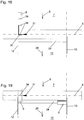
- a pressure beam 18 known per se, which in the 3 to 5 is easier to see in the front view. As is known per se, this is guided on pressure beam uprights 23 and is lowered in the sense of vibration-free sawing during the sawing process, so that the pressure beam 18 places the workpiece 1 or workpiece part 9, which is about to be sawed, in the area of the saw line 6 on the support table 3 presses on. Following the sawing process, the pressure beam 18 is then lifted again along the pressure beam upright 23 in order not to impede the further displacement and alignment of workpiece 1 or workpiece parts 9. This is known per se and need not be explained any further than the fact that a suction device is advantageously integrated in the pressure beam 18.
- the pressure bar 18 has, as in the 1 to 5 schematically indicated by the connections 38 of the suction, advantageously two connections 38 for extracting the chips produced during sawing, which can be controlled alternately by sliders (not shown here) in the suction duct, so that the suction direction can advantageously be set so that it corresponds to the direction , in which the sawing device 8 ejects the chips. It can be cut, for example, in the so-called counter-rotation, in which the sawing device moves or rotates counter to the cutting direction 31, in which the sawing device 8 is displaced during the sawing process. When sawing in the opposite direction, the cutting direction corresponds to 31 Favorably the direction in which the suction is activated by appropriate control of the suction.
- suction is carried out in the direction of the left stop rail 12 when the cutting direction 31 points in the direction towards the left stop rail 12, and vice versa.
- the suction can alternatively or additionally also take place through a gap running along the saw line in the support table 3, which is penetrated by the sawing device 8 during sawing, for example. What has been said above then preferably applies to the suction directions in relation to the cutting direction 31. In this sense, the suction devices can be controlled in a segmented manner.
- the workpiece 1 or the workpiece part 9 is fed in the first work area 7 to the saw line 6 by means of a feed device 4 which is displaceably mounted on the guide rails 21 in the feed direction 5 and in the opposite direction.
- a feed device 4 which is displaceably mounted on the guide rails 21 in the feed direction 5 and in the opposite direction.
- this has, as is known per se, Several individually or in groups controllable grippers 22 with which workpieces 1 and / or workpiece parts 9 can be gripped for transport but also for holding during the sawing process and can also be released again.
- the feed device 4 which is actually active in the first working area 7, reaches over the saw line 6 under the pressure bar 18 even when the pressure bar 18 is raised can, in order to deposit sawn-off workpiece parts 9 and, as will be explained in detail later, also grip workpiece parts 9 again and pull them back at least a little into the first working area 7 against the feed direction 5 in order to position them for the next sawing operation.
- the grippers 22 of the feed device 4 can also be raised in order to be able to move the entire feed device including the grippers 22 over workpieces 1 and / or workpiece parts 9 resting on the support table 3. This is also known per se and need not be explained further.
- the stop rails 12 and 13 provided according to the invention limit the first work area 7 in front of the saw line 6 and the second work area 10 behind the saw line 6 in the transverse direction 11, as explained at the beginning, but only the first work area 7 or only limit the second work area 10 laterally in the transverse direction 11, or, for example, also be provided in a diagonal type of arrangement.
- the transverse direction 11 is orthogonal to the feed direction 5 and here lies parallel to the drawing plane or to the support surface of the support table 3.
- the stop rails 12 and 13 delimit the second work area 10 at least in areas to the left and right.
- the waste discharge 24 extends longitudinally 11 in the transverse direction.
- This is advantageously designed as a closable opening in the support table 3.
- This closable opening can be realized, for example, by means of corresponding flaps, sliding closures or the like in the support table 3.
- the waste discharge 24 is advantageously arranged where the feed device 4, the workpiece parts 9 or their ends facing the saw line 6 and waste pieces 36 are positioned. This will be explained in more detail later.
- the waste pieces 36 are transported from the waste disposal 24 to the waste disposal 27. This can be implemented via a corresponding conveyor belt or the like, which is known per se and is integrated into the waste disposal 24. This makes waste disposal particularly easy.
- the positioning device 17 is also located in the second working area 10 behind the saw line 6. This serves to convey the workpiece parts 9 which have been created by at least one sawing process to one or the other stop rail 12 or 13. Furthermore, the positioning device 17 can also rotate the workpiece parts 9 about axes of rotation 15 arranged normal to the support surface of the support table 3. Furthermore, the positioning device 17 also advantageously allows the workpiece parts 9 to be lifted and put down in the second work area 10. In particular if the workpieces 1 or workpiece parts 9 are individual plates, the positioning device 17 can have one, two or more suction devices 20 or vacuum grippers with which they can be used Workpiece parts 9 can grip and manipulate.
- the positioning device 17 can advantageously be moved in at least two, preferably three, spatial directions 19. These are the horizontal directions aligned in the transverse direction 11 and parallel to the feed direction 5, and advantageously also those in FIG Fig. 3 vertical directions 19 shown. Suitable positioning devices 17 in the form of handling systems are known per se in the prior art and need not be explained further here. For example, if the workpieces 1 or workpiece parts 9 are stacks of plates, the positioning devices 17 can also be equipped with appropriate grippers. If no lifting of the workpiece parts 9 is provided, the positioning devices 17 can also be simple slides or the like.
- the positioning device 17 should in any case be designed such that it can transport, rotate and / or otherwise move workpiece parts 9 over the entire width of the second working area 10 between the stop rails 12 and 13. In addition, in preferred embodiments, it should also be suitable for transporting workpiece parts 9 into the storage areas 16 and picking them up there again.
- the storage areas 16 on the support table 3 can, as in the Fig. 1 and 2nd shown, outside of the second work area 10 to be arranged laterally next to the stop rails 12 and 13.
- a storage area 16 can also be a partial area within the first or second work area 7 and 10. For this purpose, there are in particular partial areas of work areas 7 and 10, which are otherwise not required when processing the sawing plan.
- the positioning device 17 with the suction devices 20 arranged thereon can also be rotated about the direction of rotation 26.
- the positioning device 17 can optionally also be used to transport the finished end formats or workpiece parts 9 in the discharge direction 28 until they are transported further in the discharge direction 28 by a further transport means, not shown in detail here.
- the mobility of the positioning device 17 is displaceable along Corresponding guides 25 are realized, some of which are arranged like a portal above the second work area 10. This does not have to be the case; one could also provide, as a corresponding positioning device 17 or as a corresponding handling device, a known industrial robot with at least one work arm or the like which can be correspondingly moved in two or three spatial directions.
- FIG. 2 A second panel dividing system 2 according to the invention is shown, the basic structure of which essentially corresponds to the first exemplary embodiment, so that the similarities are not discussed again here.
- the method according to the invention can also be carried out with this plate dividing system 2.
- the second exemplary embodiment according to Fig. 2 Several, here a total of three, feed devices 4, each with several grippers 22. This makes it possible to transport several workpiece parts 9 simultaneously and independently of one another in the feed direction 5 or in the opposite direction.
- two or more workpiece parts 9, preferably lying side by side can also be conveyed simultaneously or jointly to one of the stop rails 12 and 13 and / or simultaneously or jointly two or more workpiece parts 9 , preferably lying next to each other, are further sawn against the other stop rail 12 or 13 adjacent to the saw line 6.
- Fig. 2 drawn as an example.
- two positioning devices 17 are also provided in this exemplary embodiment in the second working area 10 behind the sawing line 6, which can otherwise be constructed in accordance with the positioning device 17 of the first exemplary embodiment.
- an intermediate storage connection 29 is also provided here, which the discharge and the Temporary storage of remaining parts during the dividing process of the workpiece 1 enables.
- Corresponding means of transport in this buffer connection 29 are not explicitly shown here. But it can, for example, be known, driven rollers, conveyor belts and the like.
- the aligner (s) 37 is or are advantageously arranged as close as possible to the saw line 6. They can advantageously be moved in transverse directions 11, and can preferably also be raised and lowered. As an alternative to the arrangement on the pressure beam 18 or on the saw carriage 30, which is also described in more detail further below, the aligner (s) 37 can also be integrated in the support table 3 as a pin or cam, which can be moved, in particular in the transverse direction 11, preferably can be raised and lowered.
- the aligners 37 are preferred individually and in the case of several aligners 37 can be controlled independently of one another.
- Fig. 3 is a variant in which two sawing devices 8 in the form of circular saw blades are arranged on a saw carriage 30 which can be moved along the saw line 6.
- the smaller saw blade 8 upstream in the cutting direction 31 is a so-called scorer.
- the rear, larger saw blade 8 is used for the actual cutting process. It is particularly expedient if the sawing process takes place in the cutting direction 31 towards the stop rail 12 or 13, against which the workpiece or workpiece part or parts 9 currently to be sawed abuts.
- the saw blades 8 can be adjustable in the vertical direction in order to be able to be lowered under the support surface of the support table 3 and lifted over it, as is known per se.
- FIG. 4 A variant of this is in Fig. 4 shown.
- the saw blade upstream in the cutting direction 31 is in each case lowered a little further in order to serve as a scorer.
- the rear saw blade is used for sawing through the workpiece 1 or the workpiece parts 9 completely Fig. 4 opposite direction of cut, the saw blades 8 can be moved correspondingly the other way around in the vertical direction, so that the front scoring device is further lowered and the rear one is displaced upwards for sawing through the workpiece 1 or the workpiece parts 9. Both saw blades can be lowered accordingly for return transport.
- Fig. 5 A variant is shown in which two saw carriages 30 can be moved along the saw line 6, one saw carriage 30 being used for sawing in one cutting direction 31 and the other saw carriage being used exclusively for sawing in the other, opposite cutting direction 31.
- the arrangement of scoring and main saw blade 8 and their vertical adjustability applies to both saw carriages 30 according to the first embodiment.
- the cutting direction 31 is always oriented in the direction towards the stop rail 12 or 13, against which the workpiece 1 or workpiece part 9 to be sawed abuts. As explained in detail above, this makes it possible to extract the sawdust produced during the sawing process as effectively as possible via the pressure beam 18 or downward through a gap running along the saw line 6 in the support table 3.
- Fig. 6 shows the raw plate or the workpiece 1 to be divided, on which the sawing plan is drawn.
- the sawing or cutting plan comprises the first cutting lines 32, second cutting lines 33, third cutting lines 34 and four cutting lines 35. If all these sawing processes have been carried out along these cutting lines 32 to 35, the final formats in the form of in Fig. 6 shown workpiece parts 9, and the hatched waste pieces 36.
- the 7 to 21 are now in a plan view the various process steps for processing the in Fig. 6 shown saw plan.
- the method according to the invention can be carried out on one of the two plate dividing systems 2 shown here by way of example from FIGS Fig. 1 and 2nd but can also be carried out on other panel sizing systems that are appropriately suitable or provided.
- the two stop rails 12 and 13 arranged in the second work area 10 as well as the saw line 6 and the waste discharge 24 are shown.
- the feed direction 5 and the discharge direction 28, as also shown in FIGS Fig. 1 and 2nd are shown.
- the respective cutting direction 31 is also shown by a corresponding arrow 31 on the saw line 6.
- the stop rails 12 and 13 in the first working area 7 are dispensed with, so that these are also not shown. However, this does not change the procedure according to the invention, which can also be carried out with stop rails 12 and 13 only or additionally in the first working area 7.
- Fig. 7 shows the situation when the first first cut 32 is made at the beginning of the method.
- the feed device 4 was activated accordingly.
- the pressure bar 18 is correspondingly lowered and then raised again, which will not be dealt with each time in the following.
- the first cuts 32 are successively made by advancing the workpiece 1 in the feed direction 5.
- First in Fig. 7 sawn waste piece 36 sawn. This can then fall into the waste disposal 24 when it is run over.
- the first workpiece part in the form of in Fig. 7 sawed-in plate strip 9 and then rotated, preferably by the positioning device 17, and conveyed towards the right stop rail 13.
- Fig. 8 shows the situation in which the last first cut 32 is carried out in order to cut off the remaining piece 36.
- the workpiece 1 does not necessarily have to be aligned with the stop rail 12 in order to carry out the first cuts.
- the workpiece 1 remains gripped in the grippers 22 of the feed device 4 all the time.
- Fig. 9 shows the process section when the workpiece part 9 sawn one after the other in the course of the first cuts with the in Fig.
- the workpiece part 9 prepositioned on the right stop rail 13 for the next sawing operation in a position in which the feed device 4 let go of the workpiece part 9 deposited on the left stop rail 12, previously sawn, and pick up the workpiece 9 resting on the right stop rail 13 can without having to move the feed device 4 in the feed direction or in the opposite direction.
- the exact alignment of the workpiece parts 9 for the next sawing process by pressing flat against one of the stop rails 12 or 13 can, preferably shortly before the lowering of the pressure beam 18 or shortly before the sawing process, by means of the aligners 37 described above or already by means of the positioning device 17 without going into each of them individually below.
- Fig. 10 In Fig. 10 can now be seen, as in the case of the prepositioned workpiece part 9 deposited on the left stop rail 12 in FIG Fig. 9 Remaining visible 36 was disposed of by the waste disposal 24 and the workpiece part 9 previously positioned on the right stop rail 13 was withdrawn by the feed device 4 to such an extent that the second cuts along this workpiece part 9 in FIG Fig. 10 drawn second cut lines 33 can be processed one after the other.
- the cutting direction 31 is drawn in the direction of the respective stop rail 13.
- the in Fig. 10 Waste provided with the reference symbol 36 falls into it when the waste discharge 24 is passed over.
- the in Fig. 11 shown final formats 9 by implementation of the corresponding second cuts along the second cut lines 33 Fig. 10 generated and transported away in the discharge direction 28. This does not apply to the remaining piece 14 resulting from these second cuts, as is shown in Fig. 11 is drawn.
- the left workpiece part 9 or remnant piece 14 is rotated by the positioning device 17 about the axis of rotation 15 which is vertical to the support surface of the support table and thus on the left for the next sawing operation Pre-positioned stop rail 12.
- the workpiece part 9 is in turn pre-positioned on the left stop rail 12, so that the feed device can simultaneously release the workpiece part 9 or rest piece 14 resting on the right stop rail 13 and can grip the other workpiece part 9 pre-positioned and aligned on the other stop rail 12 with the corresponding grippers 22 and the latter can be pulled back against the feed direction 5 via the saw line 6, in order then to make the second cuts along the in Fig. 13 perform shown second cut lines 33.
- the remaining piece 36 By opening the waste bin 24, the remaining piece 36, as in Fig. 12 is located, disposed of. While at the transition from Fig. 13 to Fig. 14 the workpiece part 9 resting on the right stop rail 13 is pre-positioned for the next sawing operation by rotating about the axis of rotation 15, the second cuts are made on the workpiece part 9 resting on the left stop rail 12 and the end formats 9 are removed in the discharge direction 28. In Fig. 15 the remaining piece 14 is then deposited again on the left stop rail 12 and the workpiece part 9 prepositioned on the right stop rail 13 is picked up, so that the third cut along the third cut line 34 can then be carried out on the right workpiece part 9, as shown in FIG Fig. 16 is shown.
- Fig. 22 shows by drawing the first, second, third and four cut lines 32, 33, 34, 35 as well as the final formats 9 and the waste parts 36 an example of another sawing plan, according to which a workpiece 1 is divided into the final formats.
- the same method according to the invention is used here, in that the corresponding method steps are processed one after the other.
- the workpiece 1 lies along the first cutting lines 32 with its longest edge parallel to the saw line 6.
- Another difference from the first exemplary embodiment is that here in the second exemplary embodiment, as with reference to FIG Fig.
- one of the workpiece parts 9 is temporarily stored in the storage area 16 outside the second work area 10, while a workpiece part 9 continues to be sawed adjacent to the left stop rail 12 and another workpiece part 9 is in the meantime placed against the right stop rail 13.
- the corresponding workpiece part 9 is transported into the storage area 16 by means of the positioning device 17, as is its retrieval and positioning on one of the stop rails 12 or 13 before this workpiece part 9 is also sawn accordingly.
- the other procedure basically corresponds to the procedure explained with regard to the first exemplary embodiment and need not be explained again here.
- each sawing or cutting plan is processed completely before the next sawing plan or the next workpiece 1 follows.
- the workpiece parts 9 of successive sawing plans are preferably not mixed together.
- the cutting plans can be optimized with regard to the position of the blanks and waste so that the alternating sawing and the workpiece handling can take place in parallel without waiting times, if possible.
Landscapes
- Life Sciences & Earth Sciences (AREA)
- Engineering & Computer Science (AREA)
- Mechanical Engineering (AREA)
- Wood Science & Technology (AREA)
- Forests & Forestry (AREA)
- Sawing (AREA)
Claims (13)
- Procédé de sciage d'au moins une pièce à usiner (1), constituée d'une plaque ou d'un empilement de plaques, avec une installation de division de plaque (2), dans lequel la pièce à usiner (1), reposant sur une table de support (3) de l'installation de division de plaque (2) pour le sciage dans une direction d'amenée (5), est amenée à une ligne de sciage (6), depuis une première zone de travail (7) de la table de support (3) agencée, vu dans la direction d'amenée (5), devant la ligne de sciage (6) de l'installation de division de plaque (2) et est sciée en au moins deux parties de pièce à usiner (9), le long de la ligne de sciage (6), au moyen d'au moins un dispositif de sciage (8) de l'installation de division de plaque (2) et dans lequel au moins une des parties de pièce à usiner (9) est transportée au-delà de la ligne de sciage (6) dans une deuxième zone de travail (10) de la table de support (3) agencée, vu dans la direction d'amenée (5), derrière la ligne de sciage (6) de l'installation de division de plaque (2), caractérisé en ce que la première zone de travail (7) et/ou la deuxième zone de travail (10) est ou sont délimitées, dans une direction transversale (11) orientée orthogonalement à la direction d'amenée (5), par deux rails de butée (12, 13) se faisant face l'un l'autre et au moins une des parties de pièce à usiner (9) est acheminée vers un des rails de butée (12, 13), pendant qu'au moins une autre des parties de pièce (9) continue d'être sciée au niveau de la ligne de sciage (6), en s'appuyant contre l'autre rail de butée (12, 13).
- Procédé selon la revendication 1, caractérisé en ce que dans des étapes de procédé réalisées l'une après l'autre alternativement dans une des étapes de procédé, au moins une des parties de pièce à usiner (9) est acheminée vers un des rails de butée (12, 13), pendant qu'au moins une autre des parties de pièce à usiner (9) continue d'être sciée au niveau de la ligne de sciage (6), en s'appuyant contre l'autre rail de butée (12, 13) et dans une étape de procédé réalisée ultérieurement, au moins une des parties de pièce à usiner (9) continue d'être sciée au niveau de la ligne de sciage (6), en s'appuyant contre l'un des rails de butée (12, 13), pendant qu'au moins une autre des parties de pièce à usiner (9) est acheminée vers l'autre rail de butée (12, 13).
- Procédé selon la revendication 1 ou 2, caractérisé en ce que tous les procédés de sciage sont réalisés jusqu'à la division complète de la pièce à usiner (1) au niveau de la ligne de sciage (6) de l'installation de division de plaque (2).
- Procédé selon l'une quelconque des revendications 1 à 3, caractérisé en ce que les rails de butée (12, 13) sont orientés respectivement parallèlement à la direction d'amenée (5).
- Procédé selon l'une quelconque des revendications 1 à 4, caractérisé en ce que la pièce à usiner (1) et/ou au moins une des parties de pièce à usiner (9) est ou sont transportées par au moins un dispositif d'avance (4) de l'installation de division de plaque (2), dans ou à l'opposé de la direction d'amenée (5) dans la première zone de travail (7) et/ou dans la deuxième zone de travail (10).
- Procédé selon la revendication 5, caractérisé en ce que l'au moins une partie de pièce à usiner (9) acheminée vers un des rails de butée (12, 13) est mise dans une position, dans laquelle elle peut à nouveau être reçue par le dispositif d'avance (4) lorsque le dispositif d'avance (4) reste dans la direction d'amenée (5), pendant qu'au moins une chute (14) de l'au moins une autre des parties de pièce à usiner (9) est déposée, après son sciage au niveau de la ligne de sciage (6), par le dispositif d'avance (4), au niveau de l'autre rail de butée (12, 13).
- Procédé selon l'une quelconque des revendications 1 à 6, caractérisé en ce qu'au moins une des parties de pièce à usiner (9) est tournée avant la poursuite du sciage de cette partie de pièce à usiner (9), de préférence dans une deuxième zone de travail (10), sur la table de support (3), autour d'un axe de rotation (15) perpendiculaire à la table de support (3) et est acheminée vers un des rails de butée (12, 13).
- Procédé selon l'une quelconque des revendications 1 à 7, caractérisé en ce qu'en plus de l'acheminement d'au moins une des parties de pièce à usiner (9) vers un des rails de butée (12, 13) et pendant le sciage de l'au moins une autre des parties de pièce à usiner (9) au niveau de la ligne de sciage (6), en s'appuyant contre l'autre rail de butée (12), au moins une partie de pièce à usiner supplémentaire (9) est entreposée dans au moins une zone de dépôt (16) sur la table de support (3).
- Procédé selon la revendication 8, caractérisé en ce que la zone de dépôt (16) est agencée à l'extérieur de la première zone de travail (7) et à l'extérieur de la deuxième zone de travail (10), de préférence dans la direction transversale (11) latéralement à côté de la première et/ou deuxième zone de travail (7, 10).
- Procédé selon l'une quelconque des revendications 1 à 9, caractérisé en ce que les parties de pièce à usiner (9) dans la deuxième zone de travail (10) sont acheminées vers un des rails de butée (12, 13), par au moins un dispositif de positionnement (17) de l'installation de division de plaque (2), prévu en particulier en plus du dispositif d'avance (4), et/ou sont tournées autour d'un axe de rotation (15) perpendiculaire à la table de support (3) et/ou sont entreposées dans une zone de dépôt (16) sur la table de support (3).
- Procédé selon l'une quelconque des revendications 1 à 10, caractérisé en ce que la pièce à usiner (1) ou partie de pièce à usiner (9) à scier est pressée par une barre de pression (18) dans la zone de la ligne de sciage (6) contre la table de support (3).
- Procédé selon l'une quelconque des revendications 1 à 11, caractérisé en ce que la pièce à usiner (1) et/ou au moins une des parties de pièce à usiner (9) est ou sont pressées, de préférence directement avant son ou leur sciage et/ou abaissement de la barre de pression (18), par au moins un aligneur (37), de préférence de l'installation de division de plaque (2), pour l'alignement contre un des rails de butée (12, 13).
- Installation de division de plaque (2), en particulier pour la réalisation d'un procédé selon l'une quelconque des revendications 1 à 12, dans laquelle l'installation de division de plaque (2) présente au moins ce qui suit :- une table de support (3) pour poser dessus au moins une pièce à usiner (1) constituée d'une plaque ou d'un empilement de plaques et- une direction d'amenée (5) pour l'amenée de la pièce à usiner (1) vers une ligne de sciage (6) de l'installation de division de plaque (2) et- une première zone de travail (7) de la table de support (3), agencée, vu dans la direction d'amenée (5), devant la ligne de sciage (6), et- au moins un dispositif de sciage (8) pour le sciage de la pièce à usiner (1), le long de la ligne de sciage (6), en au moins deux parties de pièce à usiner (9), et- une deuxième zone de travail (10) de la table de support (3), agencée, vu dans la direction d'amenée (5), derrière la ligne de sciage (6) de l'installation de division de plaque (2), et- au moins un dispositif d'avance (4) pour le transport de la pièce à usiner (1) et/ou d'au moins une des parties de pièce à usiner (9), dans ou à l'opposé de la direction d'amenée (5) dans la première zone de travail (7) et/ou dans la deuxième zone de travail (10),caractérisée en ce que l'installation de division de plaque (2) présente deux rails de butée (12, 13) se faisant face l'un l'autre pour les parties de pièce à usiner (9), lesquels délimitent la première zone de travail et/ou la deuxième zone de travail (10) dans une direction transversale (11) orientée orthogonalement à la direction d'amenée (5) et l'installation de division de plaque (2) présente en plus du dispositif d'avance (4), au moins un dispositif de positionnement (17) pour l'acheminement des parties de pièce à usiner (9) dans la deuxième zone de travail (10), vers les rails de butée (12, 13) et/ou pour la rotation des parties de pièce à usiner (9) dans la deuxième zone de travail (10), autour d'un axe de rotation (15) perpendiculaire à la table de support (3).
Priority Applications (2)
| Application Number | Priority Date | Filing Date | Title |
|---|---|---|---|
| EP13003773.2A EP2832507B1 (fr) | 2013-07-29 | 2013-07-29 | Procédé destiné et scie à panneaux horizontale au sciage de pièces à usiner |
| PCT/EP2014/001581 WO2015014423A1 (fr) | 2013-07-29 | 2014-06-11 | Procédé permettant de scier une pièce |
Applications Claiming Priority (1)
| Application Number | Priority Date | Filing Date | Title |
|---|---|---|---|
| EP13003773.2A EP2832507B1 (fr) | 2013-07-29 | 2013-07-29 | Procédé destiné et scie à panneaux horizontale au sciage de pièces à usiner |
Publications (2)
| Publication Number | Publication Date |
|---|---|
| EP2832507A1 EP2832507A1 (fr) | 2015-02-04 |
| EP2832507B1 true EP2832507B1 (fr) | 2020-04-01 |
Family
ID=48906085
Family Applications (1)
| Application Number | Title | Priority Date | Filing Date |
|---|---|---|---|
| EP13003773.2A Active EP2832507B1 (fr) | 2013-07-29 | 2013-07-29 | Procédé destiné et scie à panneaux horizontale au sciage de pièces à usiner |
Country Status (2)
| Country | Link |
|---|---|
| EP (1) | EP2832507B1 (fr) |
| WO (1) | WO2015014423A1 (fr) |
Cited By (1)
| Publication number | Priority date | Publication date | Assignee | Title |
|---|---|---|---|---|
| DE202023104430U1 (de) | 2023-08-04 | 2024-11-05 | Ima Schelling Deutschland Gmbh | Plattenaufteilanordnung |
Families Citing this family (11)
| Publication number | Priority date | Publication date | Assignee | Title |
|---|---|---|---|---|
| DE102017121956A1 (de) * | 2017-09-21 | 2019-03-21 | Homag Plattenaufteiltechnik Gmbh | Verfahren zum Bearbeiten von Werkstücken, Computerprogrammprodukt, sowie Werkstückbearbeitungsanlage |
| DE102017122868A1 (de) * | 2017-10-02 | 2019-04-04 | Homag Plattenaufteiltechnik Gmbh | Werkstückbearbeitungsanlage, sowie Verfahren zum Betreiben einer Werkstückbearbeitungsanlage |
| AT521555A1 (de) * | 2018-07-26 | 2020-02-15 | Fill Gmbh | Plattensäge |
| IT201800009492A1 (it) * | 2018-10-16 | 2020-04-16 | Biesse Spa | Macchina sezionatrice per il taglio di pannelli di legno o simili |
| IT201800009497A1 (it) * | 2018-10-16 | 2020-04-16 | Biesse Spa | Macchina sezionatrice per il taglio di pannelli di legno o simili |
| IT201800010039A1 (it) * | 2018-11-05 | 2020-05-05 | Biesse Spa | Macchina sezionatrice per il taglio di pannelli di legno o simili |
| DE102019101387A1 (de) * | 2019-01-21 | 2020-07-23 | Homag Plattenaufteiltechnik Gmbh | Verfahren zum Betreiben einer Plattenaufteilanlage, sowie Plattenaufteilanlage |
| DE102019133897A1 (de) * | 2019-12-11 | 2021-06-17 | Homag Plattenaufteiltechnik Gmbh | Werkstückbearbeitungsanlage insbesondere Plattenaufteilanlage, sowie Verfahren zum Betreiben einer Werkstückbearbeitungsanlage |
| IT202000021115A1 (it) * | 2020-09-07 | 2022-03-07 | Scm Group Spa | Macchina sezionatrice per sezionare pezzi. |
| EP4008506A1 (fr) | 2020-12-03 | 2022-06-08 | IMA Schelling Austria GmbH | Système de coupe de panneaux pour scier des panneaux |
| DE102021110333A1 (de) | 2021-04-22 | 2022-10-27 | Homag Plattenaufteiltechnik Gmbh | Vorbereitungsverfahren zum Vorbereiten der Aufteilung von mindestens zwei Werkstücken, Computerprogrammprodukt, computerlesbares Speichermedium, sowie Plattenaufteilanlage |
Family Cites Families (5)
| Publication number | Priority date | Publication date | Assignee | Title |
|---|---|---|---|---|
| DE10301885A1 (de) * | 2003-01-17 | 2004-07-29 | Otto Martin Maschinenbau Gmbh & Co | Anschlagsystem |
| ITBO20060359A1 (it) * | 2006-05-12 | 2007-11-13 | Giben Int Spa | Macchina sezionatrice di pannelli con piano di supporto mobile. |
| DE102008034049A1 (de) * | 2008-07-22 | 2010-01-28 | Holzma Plattenaufteiltechnik Gmbh | Plattenaufteilzentrum zur Komplettbearbeitung von plattenförmigen Werkstücken, insbesondere Möbelstücken |
| DE102010010746A1 (de) | 2010-03-02 | 2011-09-08 | Holzma Plattenaufteiltechnik Gmbh | Plattenbearbeitungsanlage |
| AT510304A1 (de) | 2010-08-23 | 2012-03-15 | Schelling Anlagenbau Gmbh | Verfahren zum zersägen zumindest einer platte |
-
2013
- 2013-07-29 EP EP13003773.2A patent/EP2832507B1/fr active Active
-
2014
- 2014-06-11 WO PCT/EP2014/001581 patent/WO2015014423A1/fr not_active Ceased
Non-Patent Citations (1)
| Title |
|---|
| None * |
Cited By (1)
| Publication number | Priority date | Publication date | Assignee | Title |
|---|---|---|---|---|
| DE202023104430U1 (de) | 2023-08-04 | 2024-11-05 | Ima Schelling Deutschland Gmbh | Plattenaufteilanordnung |
Also Published As
| Publication number | Publication date |
|---|---|
| EP2832507A1 (fr) | 2015-02-04 |
| WO2015014423A1 (fr) | 2015-02-05 |
Similar Documents
| Publication | Publication Date | Title |
|---|---|---|
| EP2832507B1 (fr) | Procédé destiné et scie à panneaux horizontale au sciage de pièces à usiner | |
| EP3227072B1 (fr) | Équipement diviseur de panneaux pour diviser des pièces en forme de panneaux ainsi que son procédé de fonctionnement | |
| EP3081343B1 (fr) | Installation de repartition de plaques et procédé destiné à repartir des pièces usinées en forme de plaques | |
| DE102006014454B3 (de) | Stanzvorrichtung mit Zuführeinrichtung | |
| EP2243606B1 (fr) | Installation de fabrication de plaques en lamelles de bois et procédé destiné à la fabrication de telles plaques | |
| EP4008506A1 (fr) | Système de coupe de panneaux pour scier des panneaux | |
| DE2702725A1 (de) | Plattenaufteil- und sortieranlage mit mindestens einer stapeleinrichtung | |
| DE3716666C2 (de) | Plattenaufteilanlage mit einer Längssäge und einer Quersäge | |
| DE3607454A1 (de) | Aufteilanlage fuer plattenfoermige werkstuecke | |
| EP3227069B1 (fr) | Installation de division de plaques pour diviser des pièces en forme de plaque et procédé pour faire fonctionner celle-ci | |
| EP4008508A1 (fr) | Procédé de sciage d'au moins une plaque | |
| EP1752425B1 (fr) | Dispositif de découpe de verre feuilleté et procédé pour positionner de verre feuilleté à découper | |
| EP4008507A1 (fr) | Méthode pour scier au moins une pièce | |
| AT390026B (de) | Vorrichtung zum buntaufteilen von plattenfoermigen werkstuecken | |
| DE102021125391B4 (de) | Entstapelungsvorrichtung und Holzbearbeitungsanlage mit einer derartigen Entstapelungsvorrichtung | |
| EP2481540B1 (fr) | Dispositif de sciage d'au moins deux pièces usinées sous forme de plaques ou de piles de plaques | |
| EP2578370B1 (fr) | Dispositif de coupe pour la répartition d'au moins une pièce à usiner | |
| EP2774708A1 (fr) | Scie destinée à scier au moins une pièce en forme de plaque | |
| EP4230369B1 (fr) | Installation de découpe de panneaux | |
| DE3632018A1 (de) | Aufteilanlage fuer plattenfoermige werkstuecke | |
| EP4353432A1 (fr) | Installation de division de plaques | |
| DE102005002532A1 (de) | Vorrichtung und Verfahren zum automatisierten und zeitgleichen Bereitstellen und Wechseln von mindestens zwei Rollen aus Papierbahnen oder dergleichen für einen nachgeordneten Formatschneider | |
| DE4209952C2 (de) | Einrichtung bei Buntaufteilanlagen | |
| DE102009045319B4 (de) | Formateinstellvorrichtung | |
| DE3402497C2 (de) | Vorrichtung zum Kappen von Hölzern und zum anschließenden Bearbeiten der Holzabschnitte an den Seitenkanten |
Legal Events
| Date | Code | Title | Description |
|---|---|---|---|
| 17P | Request for examination filed |
Effective date: 20130729 |
|
| AK | Designated contracting states |
Kind code of ref document: A1 Designated state(s): AL AT BE BG CH CY CZ DE DK EE ES FI FR GB GR HR HU IE IS IT LI LT LU LV MC MK MT NL NO PL PT RO RS SE SI SK SM TR |
|
| AX | Request for extension of the european patent |
Extension state: BA ME |
|
| PUAI | Public reference made under article 153(3) epc to a published international application that has entered the european phase |
Free format text: ORIGINAL CODE: 0009012 |
|
| R17P | Request for examination filed (corrected) |
Effective date: 20150505 |
|
| RBV | Designated contracting states (corrected) |
Designated state(s): AL AT BE BG CH CY CZ DE DK EE ES FI FR GB GR HR HU IE IS IT LI LT LU LV MC MK MT NL NO PL PT RO RS SE SI SK SM TR |
|
| STAA | Information on the status of an ep patent application or granted ep patent |
Free format text: STATUS: EXAMINATION IS IN PROGRESS |
|
| 17Q | First examination report despatched |
Effective date: 20170712 |
|
| GRAP | Despatch of communication of intention to grant a patent |
Free format text: ORIGINAL CODE: EPIDOSNIGR1 |
|
| STAA | Information on the status of an ep patent application or granted ep patent |
Free format text: STATUS: GRANT OF PATENT IS INTENDED |
|
| INTG | Intention to grant announced |
Effective date: 20191127 |
|
| RAP1 | Party data changed (applicant data changed or rights of an application transferred) |
Owner name: IMA SCHELLING AUSTRIA GMBH |
|
| GRAS | Grant fee paid |
Free format text: ORIGINAL CODE: EPIDOSNIGR3 |
|
| GRAJ | Information related to disapproval of communication of intention to grant by the applicant or resumption of examination proceedings by the epo deleted |
Free format text: ORIGINAL CODE: EPIDOSDIGR1 |
|
| GRAL | Information related to payment of fee for publishing/printing deleted |
Free format text: ORIGINAL CODE: EPIDOSDIGR3 |
|
| STAA | Information on the status of an ep patent application or granted ep patent |
Free format text: STATUS: EXAMINATION IS IN PROGRESS |
|
| GRAR | Information related to intention to grant a patent recorded |
Free format text: ORIGINAL CODE: EPIDOSNIGR71 |
|
| STAA | Information on the status of an ep patent application or granted ep patent |
Free format text: STATUS: GRANT OF PATENT IS INTENDED |
|
| GRAA | (expected) grant |
Free format text: ORIGINAL CODE: 0009210 |
|
| STAA | Information on the status of an ep patent application or granted ep patent |
Free format text: STATUS: THE PATENT HAS BEEN GRANTED |
|
| INTC | Intention to grant announced (deleted) | ||
| INTG | Intention to grant announced |
Effective date: 20200220 |
|
| AK | Designated contracting states |
Kind code of ref document: B1 Designated state(s): AL AT BE BG CH CY CZ DE DK EE ES FI FR GB GR HR HU IE IS IT LI LT LU LV MC MK MT NL NO PL PT RO RS SE SI SK SM TR |
|
| REG | Reference to a national code |
Ref country code: GB Ref legal event code: FG4D Free format text: NOT ENGLISH |
|
| REG | Reference to a national code |
Ref country code: CH Ref legal event code: EP Ref country code: AT Ref legal event code: REF Ref document number: 1250792 Country of ref document: AT Kind code of ref document: T Effective date: 20200415 |
|
| REG | Reference to a national code |
Ref country code: DE Ref legal event code: R096 Ref document number: 502013014505 Country of ref document: DE |
|
| REG | Reference to a national code |
Ref country code: IE Ref legal event code: FG4D Free format text: LANGUAGE OF EP DOCUMENT: GERMAN |
|
| PG25 | Lapsed in a contracting state [announced via postgrant information from national office to epo] |
Ref country code: BG Free format text: LAPSE BECAUSE OF FAILURE TO SUBMIT A TRANSLATION OF THE DESCRIPTION OR TO PAY THE FEE WITHIN THE PRESCRIBED TIME-LIMIT Effective date: 20200701 |
|
| REG | Reference to a national code |
Ref country code: NL Ref legal event code: MP Effective date: 20200401 |
|
| REG | Reference to a national code |
Ref country code: LT Ref legal event code: MG4D |
|
| PG25 | Lapsed in a contracting state [announced via postgrant information from national office to epo] |
Ref country code: SE Free format text: LAPSE BECAUSE OF FAILURE TO SUBMIT A TRANSLATION OF THE DESCRIPTION OR TO PAY THE FEE WITHIN THE PRESCRIBED TIME-LIMIT Effective date: 20200401 Ref country code: NO Free format text: LAPSE BECAUSE OF FAILURE TO SUBMIT A TRANSLATION OF THE DESCRIPTION OR TO PAY THE FEE WITHIN THE PRESCRIBED TIME-LIMIT Effective date: 20200701 Ref country code: IS Free format text: LAPSE BECAUSE OF FAILURE TO SUBMIT A TRANSLATION OF THE DESCRIPTION OR TO PAY THE FEE WITHIN THE PRESCRIBED TIME-LIMIT Effective date: 20200801 Ref country code: FI Free format text: LAPSE BECAUSE OF FAILURE TO SUBMIT A TRANSLATION OF THE DESCRIPTION OR TO PAY THE FEE WITHIN THE PRESCRIBED TIME-LIMIT Effective date: 20200401 Ref country code: GR Free format text: LAPSE BECAUSE OF FAILURE TO SUBMIT A TRANSLATION OF THE DESCRIPTION OR TO PAY THE FEE WITHIN THE PRESCRIBED TIME-LIMIT Effective date: 20200702 Ref country code: LT Free format text: LAPSE BECAUSE OF FAILURE TO SUBMIT A TRANSLATION OF THE DESCRIPTION OR TO PAY THE FEE WITHIN THE PRESCRIBED TIME-LIMIT Effective date: 20200401 Ref country code: CZ Free format text: LAPSE BECAUSE OF FAILURE TO SUBMIT A TRANSLATION OF THE DESCRIPTION OR TO PAY THE FEE WITHIN THE PRESCRIBED TIME-LIMIT Effective date: 20200401 Ref country code: NL Free format text: LAPSE BECAUSE OF FAILURE TO SUBMIT A TRANSLATION OF THE DESCRIPTION OR TO PAY THE FEE WITHIN THE PRESCRIBED TIME-LIMIT Effective date: 20200401 Ref country code: PT Free format text: LAPSE BECAUSE OF FAILURE TO SUBMIT A TRANSLATION OF THE DESCRIPTION OR TO PAY THE FEE WITHIN THE PRESCRIBED TIME-LIMIT Effective date: 20200817 |
|
| PG25 | Lapsed in a contracting state [announced via postgrant information from national office to epo] |
Ref country code: RS Free format text: LAPSE BECAUSE OF FAILURE TO SUBMIT A TRANSLATION OF THE DESCRIPTION OR TO PAY THE FEE WITHIN THE PRESCRIBED TIME-LIMIT Effective date: 20200401 Ref country code: LV Free format text: LAPSE BECAUSE OF FAILURE TO SUBMIT A TRANSLATION OF THE DESCRIPTION OR TO PAY THE FEE WITHIN THE PRESCRIBED TIME-LIMIT Effective date: 20200401 Ref country code: HR Free format text: LAPSE BECAUSE OF FAILURE TO SUBMIT A TRANSLATION OF THE DESCRIPTION OR TO PAY THE FEE WITHIN THE PRESCRIBED TIME-LIMIT Effective date: 20200401 |
|
| PG25 | Lapsed in a contracting state [announced via postgrant information from national office to epo] |
Ref country code: AL Free format text: LAPSE BECAUSE OF FAILURE TO SUBMIT A TRANSLATION OF THE DESCRIPTION OR TO PAY THE FEE WITHIN THE PRESCRIBED TIME-LIMIT Effective date: 20200401 |
|
| REG | Reference to a national code |
Ref country code: DE Ref legal event code: R097 Ref document number: 502013014505 Country of ref document: DE |
|
| PG25 | Lapsed in a contracting state [announced via postgrant information from national office to epo] |
Ref country code: RO Free format text: LAPSE BECAUSE OF FAILURE TO SUBMIT A TRANSLATION OF THE DESCRIPTION OR TO PAY THE FEE WITHIN THE PRESCRIBED TIME-LIMIT Effective date: 20200401 Ref country code: EE Free format text: LAPSE BECAUSE OF FAILURE TO SUBMIT A TRANSLATION OF THE DESCRIPTION OR TO PAY THE FEE WITHIN THE PRESCRIBED TIME-LIMIT Effective date: 20200401 Ref country code: SM Free format text: LAPSE BECAUSE OF FAILURE TO SUBMIT A TRANSLATION OF THE DESCRIPTION OR TO PAY THE FEE WITHIN THE PRESCRIBED TIME-LIMIT Effective date: 20200401 Ref country code: DK Free format text: LAPSE BECAUSE OF FAILURE TO SUBMIT A TRANSLATION OF THE DESCRIPTION OR TO PAY THE FEE WITHIN THE PRESCRIBED TIME-LIMIT Effective date: 20200401 Ref country code: ES Free format text: LAPSE BECAUSE OF FAILURE TO SUBMIT A TRANSLATION OF THE DESCRIPTION OR TO PAY THE FEE WITHIN THE PRESCRIBED TIME-LIMIT Effective date: 20200401 |
|
| PLBE | No opposition filed within time limit |
Free format text: ORIGINAL CODE: 0009261 |
|
| STAA | Information on the status of an ep patent application or granted ep patent |
Free format text: STATUS: NO OPPOSITION FILED WITHIN TIME LIMIT |
|
| PG25 | Lapsed in a contracting state [announced via postgrant information from national office to epo] |
Ref country code: SK Free format text: LAPSE BECAUSE OF FAILURE TO SUBMIT A TRANSLATION OF THE DESCRIPTION OR TO PAY THE FEE WITHIN THE PRESCRIBED TIME-LIMIT Effective date: 20200401 Ref country code: PL Free format text: LAPSE BECAUSE OF FAILURE TO SUBMIT A TRANSLATION OF THE DESCRIPTION OR TO PAY THE FEE WITHIN THE PRESCRIBED TIME-LIMIT Effective date: 20200401 Ref country code: MC Free format text: LAPSE BECAUSE OF FAILURE TO SUBMIT A TRANSLATION OF THE DESCRIPTION OR TO PAY THE FEE WITHIN THE PRESCRIBED TIME-LIMIT Effective date: 20200401 |
|
| REG | Reference to a national code |
Ref country code: CH Ref legal event code: PL |
|
| 26N | No opposition filed |
Effective date: 20210112 |
|
| GBPC | Gb: european patent ceased through non-payment of renewal fee |
Effective date: 20200729 |
|
| REG | Reference to a national code |
Ref country code: BE Ref legal event code: MM Effective date: 20200731 |
|
| PG25 | Lapsed in a contracting state [announced via postgrant information from national office to epo] |
Ref country code: CH Free format text: LAPSE BECAUSE OF NON-PAYMENT OF DUE FEES Effective date: 20200731 Ref country code: LI Free format text: LAPSE BECAUSE OF NON-PAYMENT OF DUE FEES Effective date: 20200731 Ref country code: GB Free format text: LAPSE BECAUSE OF NON-PAYMENT OF DUE FEES Effective date: 20200729 Ref country code: LU Free format text: LAPSE BECAUSE OF NON-PAYMENT OF DUE FEES Effective date: 20200729 |
|
| PG25 | Lapsed in a contracting state [announced via postgrant information from national office to epo] |
Ref country code: BE Free format text: LAPSE BECAUSE OF NON-PAYMENT OF DUE FEES Effective date: 20200731 Ref country code: SI Free format text: LAPSE BECAUSE OF FAILURE TO SUBMIT A TRANSLATION OF THE DESCRIPTION OR TO PAY THE FEE WITHIN THE PRESCRIBED TIME-LIMIT Effective date: 20200401 |
|
| PG25 | Lapsed in a contracting state [announced via postgrant information from national office to epo] |
Ref country code: IE Free format text: LAPSE BECAUSE OF NON-PAYMENT OF DUE FEES Effective date: 20200729 |
|
| PG25 | Lapsed in a contracting state [announced via postgrant information from national office to epo] |
Ref country code: TR Free format text: LAPSE BECAUSE OF FAILURE TO SUBMIT A TRANSLATION OF THE DESCRIPTION OR TO PAY THE FEE WITHIN THE PRESCRIBED TIME-LIMIT Effective date: 20200401 Ref country code: MT Free format text: LAPSE BECAUSE OF FAILURE TO SUBMIT A TRANSLATION OF THE DESCRIPTION OR TO PAY THE FEE WITHIN THE PRESCRIBED TIME-LIMIT Effective date: 20200401 Ref country code: CY Free format text: LAPSE BECAUSE OF FAILURE TO SUBMIT A TRANSLATION OF THE DESCRIPTION OR TO PAY THE FEE WITHIN THE PRESCRIBED TIME-LIMIT Effective date: 20200401 |
|
| PG25 | Lapsed in a contracting state [announced via postgrant information from national office to epo] |
Ref country code: MK Free format text: LAPSE BECAUSE OF FAILURE TO SUBMIT A TRANSLATION OF THE DESCRIPTION OR TO PAY THE FEE WITHIN THE PRESCRIBED TIME-LIMIT Effective date: 20200401 |
|
| PGFP | Annual fee paid to national office [announced via postgrant information from national office to epo] |
Ref country code: FR Payment date: 20240725 Year of fee payment: 12 |
|
| PGFP | Annual fee paid to national office [announced via postgrant information from national office to epo] |
Ref country code: DE Payment date: 20250728 Year of fee payment: 13 |
|
| PGFP | Annual fee paid to national office [announced via postgrant information from national office to epo] |
Ref country code: IT Payment date: 20250721 Year of fee payment: 13 |
|
| PGFP | Annual fee paid to national office [announced via postgrant information from national office to epo] |
Ref country code: AT Payment date: 20250722 Year of fee payment: 13 |
|
| PG25 | Lapsed in a contracting state [announced via postgrant information from national office to epo] |
Ref country code: FR Free format text: LAPSE BECAUSE OF NON-PAYMENT OF DUE FEES Effective date: 20250731 |