EP2832509A1 - Dispositif de revêtement et module d'activation pour un dispositif de revêtement - Google Patents
Dispositif de revêtement et module d'activation pour un dispositif de revêtement Download PDFInfo
- Publication number
- EP2832509A1 EP2832509A1 EP14002337.5A EP14002337A EP2832509A1 EP 2832509 A1 EP2832509 A1 EP 2832509A1 EP 14002337 A EP14002337 A EP 14002337A EP 2832509 A1 EP2832509 A1 EP 2832509A1
- Authority
- EP
- European Patent Office
- Prior art keywords
- hot gas
- coating material
- coating
- heating
- gas channel
- Prior art date
- Legal status (The legal status is an assumption and is not a legal conclusion. Google has not performed a legal analysis and makes no representation as to the accuracy of the status listed.)
- Granted
Links
Images



Classifications
-
- B—PERFORMING OPERATIONS; TRANSPORTING
- B27—WORKING OR PRESERVING WOOD OR SIMILAR MATERIAL; NAILING OR STAPLING MACHINES IN GENERAL
- B27D—WORKING VENEER OR PLYWOOD
- B27D5/00—Other working of veneer or plywood specially adapted to veneer or plywood
- B27D5/003—Other working of veneer or plywood specially adapted to veneer or plywood securing a veneer strip to a panel edge
Definitions
- the invention relates to a device for coating (coating apparatus) a surface region of a workpiece with a coating material which can be activated by a heated gas. DESCRIPTION OF THE PREFERRED EMBODIMENTS The invention also relates to an activation module for a coating device having the features in the preamble of claim 8.
- plates made of solid wood and wood-based materials use.
- the latter are usually made of glued and compressed wood chips.
- Many of these wood-based panels are already provided ex works with a coating, which is regularly limited to the upper and lower sides. At least the remaining in the later field of view narrow sides of the plates therefore require their subsequent coating.
- Suitable coatings consist in particular of plastics, which are also known as edge bands and strips.
- the connection between plate and coating is usually cohesive.
- a suitable adhesive can be applied shortly before the application of the coating on the same and / or on the surface region of the plate to be coated. These are usually hot melt adhesives.
- some coatings already have an initially inactive and activatable only by heating additional layer of hot melt adhesive.
- hot melt adhesive is disadvantageous in that it sometimes appears visually unattractive in the edge region of the plates.
- coating materials have already been developed, which allow the formation of a so-called "zero joint".
- the materials used in this case do not require an additional adhesive layer, since they either consist of a thermoplastic or have at least one polymeric functional layer. Consequently, the material is adapted to be fused at least on the side of its functional layer.
- a laser can be used for the melting of the functional layer, which laser is directed to its functional layer shortly before the coating material is pressed on.
- coating materials to be melted in this way are therefore also familiar under the term "laser edge bands". It has been known for some time that such coating materials can also be melted with hot air.
- a device for coating the narrow sides of a workpiece with such adhesive-free heat-activatable coating material in the form of an edge strip has become known.
- a feed device for the edge strip and a pressing device for pressing the heat-activated edge strip to the narrow side of the workpiece further comprises a heating device.
- the heating device serves to bring the hot air required for activating the edge strip to the required activation temperature.
- the air to be heated is already injected under pressure into the heating device. Subsequently, the hot air heated therein passes through a channel from which it is inflated via at least one outlet slot to a region of the edge strip to be activated.
- the pressure of the exiting hot air is above atmospheric pressure.
- a sufficiently rapid transport and a rapid transfer of heat energy to the coating material is to be achieved.
- corresponding heating elements of tube bundles or sintered plates may be arranged within the heating device, the generated heat of which is given off to the air flowing around it.
- the heating device is thermally insulated from the environment.
- a device for coating workpieces which comprises at least two joining devices in addition to a feed and a pressing device.
- the joining devices are to configured to apply an adhesive to a coating material or to activate an already applied adhesive.
- the arrangement of the at least two joining devices the probability of failure of the device can be reduced.
- different activation methods can be performed with the same device, for example, in parallel or as needed.
- hot air allows a simpler and thus more favorable compared to laser construction.
- the use of known in the art hot air blowers for melting of coating materials are limited. This is usually due to the fact that the heat energy generated during their transport via the hot air to their place of use rapidly cools despite any insulation measures.
- the heating power of the heating device can not be increased arbitrarily. Nevertheless, in order to transfer the required heat energy in sufficient height to the continuous coating material, its residence time in the region of exposure to the hot air must be increased. However, this also extends the maximum possible cycle times adversely.
- a particular challenge is to make the continuous coating material more suitable Place with sufficiently warm hot air to apply.
- the temperature of the hot air does not suffice at the time of its impact on the coating material, it can not provide a durable bond due to insufficient activation.
- the temperature of the impinging hot air is too high, the coating material may suffer visual disadvantages or even be damaged.
- the object of the present invention is to improve a coating device of the type indicated above in such a way that it enables a more efficient heating of coating materials and thus permits higher process speeds. Furthermore, an activation module for heat-activatable materials for coating workpieces is to be presented, with which a simple and efficient retrofitting of existing edge banding on the use of hot air is feasible.
- the solution of the first part of this task consists according to the invention in a coating apparatus having the features of claim 1.
- the second part of this object is achieved by an activation module for a coating apparatus having the features of claim 8.
- an apparatus for coating a surface area of a workpiece is provided.
- the device for coating is also designated as a coating device, so that the terms used here are to be regarded as synonymous.
- the coating to be carried out with the aid of the coating device is carried out using a coating material that can be activated by a heated gas.
- the coating device according to the invention comprises a fan and a heating device and a pressure device.
- the heater here serves to heat the gas.
- the blower is intended to convey and compress the gas.
- the direction of flowing gas from the fan to the heater is such that the heater may be located downstream of the fan.
- the gas used is advantageously air, in particular ambient air.
- gases or gas mixtures are also conceivable which either enable a better heat transfer and / or promote the activation of the coating material.
- the existing pressure device which in particular has a pressure roller, is designed to press a region of the coating material activated by the heated gas against at least one partial region of the surface region to be coated.
- a hot gas channel connected in a fluid-conducting manner to the fan is arranged.
- the hot gas channel has at least one outlet region for the heated gas.
- the hot gas channel is designed to flow directly to the area of the coating material to be activated with the heated gas.
- the heating device is arranged at least in sections within the hot gas channel. In other words, this omits the otherwise customary heating of the gas at a location opposite the coating material and its subsequent transfer.
- the resulting advantage lies in the heating of the gas only shortly before its impact on the area of the coating material to be activated.
- the present inventive design reduces the known but disadvantageous transmission of the gas after its heating by the heater to a minimum. As a result, the otherwise existing heat losses are completely avoided or largely limited. Consequently, the hot-energy-enriched hot gas strikes the coating material almost immediately after being heated at the approximately maximum temperature.
- the hot gas impinging on the coating material is still so high in energy that the process speed for the application of the coating can advantageously be increased.
- the heating occurring only shortly before impacting the coating material results in more efficient heating of the coating material without overheating and possibly damaging it due to heat losses to be observed.
- the heater may be such that its heated areas can flow around and / or flow through the gas. It is advantageous to provide a large surface in order to realize as large as possible contact for the transfer of heat energy to the gas within a very short time.
- any side walls and / or installations of the heating device can be heated, which come into contact with the flowing gas.
- the heating itself can be done for example via heat-conducting media.
- the medium may be, for example, a gaseous or liquid fluid, with which the contact areas are exposed to the gas.
- the heating device preferably has heating elements, for example at least one electrically operated heating wire. This can be arranged for example as a heating coil within the hot gas channel. The gas flowing past the heating wire cools it in an advantageous manner and at the same time heats the gas to the necessary temperature.
- the preferred plurality of heating elements can be operated separately from each other, for example by an electrical control or regulation according to an advantageous embodiment. It can thereby be achieved that over the width of the coating material, the edge band, a predetermined temperature distribution can be adjusted. For example, it may be provided that the edges of the coating are heated more strongly than the middle part.
- the outlet region for the hot gas can be arranged at the end of the hot gas channel.
- the hot gas duct may have an open end in its extension as the outlet region.
- this end can also be covered by a wall, through which the outlet region is arranged, for example in the form of at least one opening. It is also conceivable a plurality of openings, which, for example when using a grid structure as a wall or its perforation caused by holes or slots.
- the heating device extends within the hot gas channel up to its outlet region. This is to ensure that the gas is still heated by the heater until shortly before it exits the outlet region of the hot gas channel. As a result, the path for possible cooling of the gas between the outlet region and the region of the coating material to be heated is advantageously shortened to a minimum.
- the outlet area can of course also be located on a peripheral side of the hot gas channel and thus be arranged laterally. Also in this case, it is provided that the heating device extends at least as far within the hot gas channel that it is also present within the outlet region. In other words, this should ensure that the heating device offers the possibility of heating the gas until shortly before it leaves the outlet region.
- the heating device is therefore to be arranged in principle until before or even into the outlet region.
- the coating material is guided at an angle to the surface region of the workpiece to be coated.
- the coating device according to the invention can also be designed in this way be that a flow direction of the hot gas channel and the feeding direction of the coating material to the pressure device at an angle of less than 90 ° between them.
- the hot gas duct can have a wedge-shaped end section.
- this end portion is formed such that its free end extends parallel to the feed direction of the coating material.
- the outlet region of the hot gas channel is arranged in its free end running parallel to the feed direction of the coating material.
- the distance of the gas to be covered between its heating and impinging on the coating material is thereby significantly reduced.
- an exhaust gas shaft corresponding to the hot gas duct may be provided.
- the exhaust gas shaft is designed to receive the gas flowing out of the hot gas channel and consequently heated gas after it has flowed on the coating material or even in the absence thereof and / or to catch.
- the gas is then correspondingly discharged via a suitable forwarding.
- the arrangement of the exhaust shaft advantageously ensures that no heat accumulation can occur in the region of the pressure device. In this way, a highly controlled heating of the respective coating material takes place. Overall, any components arranged in this area are not adversely affected by heat as a result. This unwanted heat application could limit the functioning of these components, increase their wear or even destroy them directly. Furthermore, this also ensures that the coating material is not heated by any deflected gas at areas that are not (yet) to be heated.
- the exhaust gas shaft can also be arranged to form a feed gap with respect to the hot gas channel.
- the exhaust shaft and the hot gas channel can be directly opposite each other.
- the parts facing each other are preferably the outlet area and a junction the exhaust shaft.
- the respective coating material is particularly preferably guided through this feed gap to the pressure device.
- the openings may be, for example, slots, which are adapted in width and height to the coating material to be performed.
- the hot gas channel can be subdivided into at least two or more channels.
- the subdivision can be effected, for example, by one or more partitions arranged within the hot gas channel.
- the hot gas duct can also be composed of two or more structurally separate channels.
- the hot gas channel has a closure means which is designed to close the at least two channels either separately or together with respect to the blower.
- the respective channels likewise have outlet regions which are separate from one another.
- the gas conveyed and compressed via the fan can be conducted through one or more channels and thus out of one or more outlet regions out on the coating material.
- the individual channels can be arranged next to or above each other. Accordingly, their respective outlet areas are either side by side or one above the other.
- the or the other channels are correspondingly closed by the closure means.
- wider materials can then also be processed by opening at least one further channel via the closure means.
- the closure means may be, for example, a flap or an arrangement of a plurality of independently operable flaps or linearly movable bulkheads.
- said channels of the hot gas duct may also be arranged relative to one another such that the width, but rather the width, of the producible stream of heated gas can be set by their respective connection or disconnection. That way you can Also, such coating materials are processed, which require a mutually different attachment concept. Specifically, it is conceivable that in this way with one and the same device materials can be processed, which either have a heat-activatable glue layer or else have a corresponding functional layer and consequently are to be melted themselves.
- each of the channels has its own heating device. In this way, the required heating of the gas passing through the respective channel can be regulated. It is conceivable that as a result the coating material can be acted on at different areas simultaneously with differently heated gas.
- the separate heaters are advantageous in that only the channel (s) carrying the gas is actively heated by its heater. In this way the most economical operation of the device is possible.
- a coating device which has a high flexibility with respect to the coating materials to be processed.
- the heating which takes place shortly before the gas escapes from the hot gas channel enables extremely efficient heating of the respective coating materials.
- the present invention provides a device which exploits the advantages of gas heating of coating materials while overcoming its disadvantages.
- the invention is directed to an inventive activation module, which is suitable for use in a coating apparatus, in particular in the coating apparatus described above.
- the aim here is the retrofitting of existing devices and systems with such activation module according to the invention in order to use the advantageous principles of the present invention in a simple manner, for example, in already in use edgebanders can.
- the activation module described below is suitable for a device for coating a surface region of a workpiece with a coating material that can be activated by a heated gas.
- the activation module comprises a blower and a heater for heating the gas.
- a hot gas duct connected in a fluid-conducting manner to the fan is also provided in this case, which has an outlet region for the heated gas.
- Said hot gas duct is adapted to flow directly to the area of the coating material to be activated with the heated gas.
- the heating device for heating the gas passing through the hot gas channel is arranged at least in sections within this hot gas channel.
- the hot gas duct may be subdivided into at least two channels.
- the hot gas duct may comprise a closure means which is designed to close the at least two ducts either separately from one another or together with respect to the blower.
- Fig. 1 shows a known from the prior art apparatus for coating a workpiece in the form of a Kantenanleimmaschine 1.
- the edge banding machine 1 is adapted to give adhesive to a workpiece 2 and to add a coating material 3 in the form of an edge strip with the workpiece 2.
- the workpiece 2 is guided by means of a transport chain 4 parallel to the edge banding machine 1 in a transport direction a.
- a surface region 5 of the workpiece 2 to be coated is wetted with the adhesive.
- the workpiece 2 is guided past an adhesive indication 6.
- the surface region 5 of the workpiece 2 to be coated comes into contact with the adhesive in a manner not shown, as a result of which the adhesive deposits on the workpiece 2.
- a pressure device 7 is further provided, which includes in particular a pressure roller 8. Furthermore, the edge banding machine 1 has a separating knife 9 in order to be able to cut the coating material 3 to a corresponding extent. In order to be able to provide further coating material 3a, the edge banding machine 1 also has a magazine 10 which holds a supply of coating material 3a.
- Kantenanleimaschine 1 has in the areas of the adhesive 6 and the pressure device 7 each have an installation space 11, 12, which can serve for receiving an activation module according to the invention after removal of the adhesive 6.
- the coating device 13 described below which emerges from the further figures, can be designed as an independent coating device 13 or as an edge banding machine 1 retrofitted with the activation module according to the invention Fig. 1 viewed become. Consequently, the following statements relate to both possible variants.
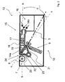
- Fig. 2 Now shows the coating device 13 according to the invention, which for coating the surface region 5 of the workpiece 2 not shown here with a activatable by a heated gas 14a coating material third
- the coating device 13 has, in addition to the pressure device 7, which is designed in particular as a pressure roller, the activation module 15 according to the invention, which comprises a fan 16 and a heating device 17 for heating the gas 14b.
- a flow direction b of the gas 14 a, 14 b extends from the blower 16 to the coating material 3.
- Said flow direction b is predetermined by a hot gas channel 18, which is arranged in the region of the pressure device 7 and connected in a correspondingly fluid-conducting manner to the blower 16.
- the heating device 17 is arranged inside the hot gas channel 18.
- the hot gas passage 18 has a wedge-shaped end portion 19 having an outlet portion 20 for the heated gas 14a.
- the hot gas channel 18 is designed to flow directly to a region 21 of the coating material 3 to be activated with the heated gas 14a.
- the coating material 3 to be supplied to the hot gas channel 18 and then to the pressure device 7 has a feed direction c extending parallel to the outlet region 20.
- additional guide rollers 22 in front of the pressure device 7 arranged additional guide rollers 22, so that the further course of the supplied coating material 3 is slightly inclined from its origin from the magazine 10 not shown here ago relative to the feed direction c.
- the activation module 13 or the coating device 1 comprises an exhaust gas shaft 22 corresponding to the hot gas channel 18.
- the exhaust gas shaft 22 is funnel-shaped with respect to its junction and arranged in front of the outlet region 20 of the hot gas channel 18 such that the exhaust gas shaft 22 from the hot gas channel 18 receive outflowing heated gas 14a after the flow of the coating material 3 and can discharge via a line 23.
- the exhaust gas shaft 22 is arranged to form a feed gap 24 with respect to the hot gas channel 18. In this way, the coating material 3 can be guided through the feed gap 24 to the pressure device 7, wherein it is activated immediately above the heated gas 14a.
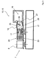
- Fig. 3 shows a detail of the activation module 15 Fig. 2 or the coating device 13 in a side view.
- a variant embodiment of the hot gas channel 18 is shown.
- the hot gas channel 18 is subdivided into at least two channels 25, 26.
- a partition wall 27 is arranged in the interior of the hot gas channel 18, which divides the hot gas channel 18 into a present upper channel 25 and a lower channel 26.
- a closure means 28 is disposed within the hot gas channel 18. The closure means 28 is arranged between the two channels 25, 26 such that they can be closed either separately from one another or together with respect to the blower 16.
- each individual one of the channels 25, 26 of the hot gas duct 18 has its own heating device 17.
- the present two heaters 17 are operated in a manner not shown in detail either separately or together.
- a section of the hot gas channel 18 emerges in a further variant.
- the heating device 17 is not arranged centrally but at the end of the hot gas channel 18. As a result, the heating device 17 extends within the hot gas channel 18 as far as its outlet region 20.
- FIG. 12 depicts a view of the outlet region (s) 20 of the hot gas channel 18 Fig. 3 , In both channels 25, 26, the respective heaters 17 are indicated by broken lines. In the presentation of Fig. 5 3 illustrates that the respective outlet regions 20 of the individual channels 25, 26 have individual openings 29 from which the heated gas 14a can flow.
Landscapes
- Life Sciences & Earth Sciences (AREA)
- Engineering & Computer Science (AREA)
- Mechanical Engineering (AREA)
- Wood Science & Technology (AREA)
- Forests & Forestry (AREA)
- Coating Apparatus (AREA)
Priority Applications (1)
| Application Number | Priority Date | Filing Date | Title |
|---|---|---|---|
| PL14002337T PL2832509T3 (pl) | 2013-07-30 | 2014-07-08 | Moduł aktywacyjny dla urządzenia do powlekania z urządzeniem do powlekania |
Applications Claiming Priority (1)
| Application Number | Priority Date | Filing Date | Title |
|---|---|---|---|
| DE102013012644.4A DE102013012644A1 (de) | 2013-07-30 | 2013-07-30 | Beschichtungsvorrichtung sowie Aktivierungsmodul für eine Beschichtungsvorrichtung |
Publications (3)
| Publication Number | Publication Date |
|---|---|
| EP2832509A1 true EP2832509A1 (fr) | 2015-02-04 |
| EP2832509B1 EP2832509B1 (fr) | 2019-10-30 |
| EP2832509B8 EP2832509B8 (fr) | 2019-12-18 |
Family
ID=51210203
Family Applications (1)
| Application Number | Title | Priority Date | Filing Date |
|---|---|---|---|
| EP14002337.5A Active EP2832509B8 (fr) | 2013-07-30 | 2014-07-08 | Module d'activation pour un dispositif de revêtement avec dispositif de revêtement |
Country Status (4)
| Country | Link |
|---|---|
| EP (1) | EP2832509B8 (fr) |
| DE (1) | DE102013012644A1 (fr) |
| ES (1) | ES2764123T3 (fr) |
| PL (1) | PL2832509T3 (fr) |
Cited By (2)
| Publication number | Priority date | Publication date | Assignee | Title |
|---|---|---|---|---|
| EP3372364A1 (fr) * | 2017-03-07 | 2018-09-12 | Lemtapes Oy | Procédé et appareil d'activation d'adhésif |
| CN109070380A (zh) * | 2016-01-15 | 2018-12-21 | 希菲斯有限公司 | 封边设备和方法 |
Families Citing this family (4)
| Publication number | Priority date | Publication date | Assignee | Title |
|---|---|---|---|---|
| DE202015005977U1 (de) | 2015-03-25 | 2015-09-15 | Christof Schulte-Göbel | Aktivierungseinrichtung für eine Vorrichtung zur Aufbringung von insbesondere kleberlos wärmeaktivierbaren Kantenstreifen auf plattenartige Werkstücke |
| DE102019113270A1 (de) * | 2019-05-20 | 2020-11-26 | Homag Gmbh | Heißgaseinrichtung zum Bereitstellen von Heißgas sowie Beschichtungsvorrichtung und Verfahren zum Beschichten von Werkstücken |
| DE102019114105A1 (de) * | 2019-05-27 | 2020-12-03 | Homag Gmbh | Verfahren und Vorrichtung zum Beschichten von Werkstücken |
| DE102020131506A1 (de) | 2020-11-27 | 2022-06-02 | Homag Gmbh | Vorrichtung und Verfahren zum Beschichten eines Werkstücks |
Citations (5)
| Publication number | Priority date | Publication date | Assignee | Title |
|---|---|---|---|---|
| FR2318736A1 (fr) * | 1975-07-21 | 1977-02-18 | Klessmann Ima Norte Maschfab | Procede et dispositif pour coller un materiau de bordure sur la tranche de pieces en forme de plaques en materiau a base de bois |
| US4222812A (en) * | 1978-06-29 | 1980-09-16 | Lof Plastics, Inc. | Hot air edge banding machine |
| EP2243619A1 (fr) | 2009-04-22 | 2010-10-27 | Homag Holzbearbeitungssysteme AG | Dispositif et procédé destinés au revêtement de pièces à usiner |
| DE102011015898A1 (de) | 2011-04-01 | 2012-10-04 | Christof Schulte-Göbel | Schmalflächenbeschichtungsvorrichtung und Verfahren zum Aufbringen einer kleberfrei wärmeaktivierbaren Kantenbeschichtung mittels Heißluft oder Heißgas |
| WO2014019847A1 (fr) * | 2012-08-03 | 2014-02-06 | Homag Holzbearbeitungssysteme Gmbh | Procédé et dispositif de revêtement de pièces |
Family Cites Families (5)
| Publication number | Priority date | Publication date | Assignee | Title |
|---|---|---|---|---|
| GB191512694A (en) * | 1915-09-03 | 1916-09-04 | Arthur Francis Berry | Improvements in or relating to Apparatus for Heating and otherwise Treating the Air Supply to Buildings and the like. |
| CH564174A5 (fr) * | 1973-02-20 | 1975-07-15 | Petz Siegfried Elektro Waerme | |
| DE3732157A1 (de) * | 1987-09-24 | 1989-05-18 | Thomas Hebel | Umleimer-klebegeraet |
| JP2005001447A (ja) * | 2003-06-10 | 2005-01-06 | Denso Corp | 電気ヒータ、暖房用熱交換器および車両用空調装置 |
| KR100762734B1 (ko) * | 2006-02-10 | 2007-10-02 | 김성일 | 전기 온풍기용의 유도가열 발열체와 이를 이용한 온풍기 |
-
2013
- 2013-07-30 DE DE102013012644.4A patent/DE102013012644A1/de not_active Withdrawn
-
2014
- 2014-07-08 ES ES14002337T patent/ES2764123T3/es active Active
- 2014-07-08 EP EP14002337.5A patent/EP2832509B8/fr active Active
- 2014-07-08 PL PL14002337T patent/PL2832509T3/pl unknown
Patent Citations (5)
| Publication number | Priority date | Publication date | Assignee | Title |
|---|---|---|---|---|
| FR2318736A1 (fr) * | 1975-07-21 | 1977-02-18 | Klessmann Ima Norte Maschfab | Procede et dispositif pour coller un materiau de bordure sur la tranche de pieces en forme de plaques en materiau a base de bois |
| US4222812A (en) * | 1978-06-29 | 1980-09-16 | Lof Plastics, Inc. | Hot air edge banding machine |
| EP2243619A1 (fr) | 2009-04-22 | 2010-10-27 | Homag Holzbearbeitungssysteme AG | Dispositif et procédé destinés au revêtement de pièces à usiner |
| DE102011015898A1 (de) | 2011-04-01 | 2012-10-04 | Christof Schulte-Göbel | Schmalflächenbeschichtungsvorrichtung und Verfahren zum Aufbringen einer kleberfrei wärmeaktivierbaren Kantenbeschichtung mittels Heißluft oder Heißgas |
| WO2014019847A1 (fr) * | 2012-08-03 | 2014-02-06 | Homag Holzbearbeitungssysteme Gmbh | Procédé et dispositif de revêtement de pièces |
Cited By (2)
| Publication number | Priority date | Publication date | Assignee | Title |
|---|---|---|---|---|
| CN109070380A (zh) * | 2016-01-15 | 2018-12-21 | 希菲斯有限公司 | 封边设备和方法 |
| EP3372364A1 (fr) * | 2017-03-07 | 2018-09-12 | Lemtapes Oy | Procédé et appareil d'activation d'adhésif |
Also Published As
| Publication number | Publication date |
|---|---|
| PL2832509T3 (pl) | 2020-05-18 |
| EP2832509B8 (fr) | 2019-12-18 |
| EP2832509B1 (fr) | 2019-10-30 |
| ES2764123T3 (es) | 2020-06-02 |
| DE102013012644A1 (de) | 2015-02-05 |
Similar Documents
| Publication | Publication Date | Title |
|---|---|---|
| EP2832509B1 (fr) | Module d'activation pour un dispositif de revêtement avec dispositif de revêtement | |
| EP2782725B1 (fr) | Arrangement de tuyères pour un dispositif de revetêment latéral par bandes pour alimentation d'air chaud sur les bandes couvertes d'un revetement activable par chaleur ou de thermocolle ou sur la piece et dispositif de collage de bandes comprenant un tel arrangement | |
| EP2826136B1 (fr) | Paquet de tôles et procédé pour le produire | |
| DE102011015898A1 (de) | Schmalflächenbeschichtungsvorrichtung und Verfahren zum Aufbringen einer kleberfrei wärmeaktivierbaren Kantenbeschichtung mittels Heißluft oder Heißgas | |
| EP2433769B1 (fr) | Dispositif et procédé de revêtement de pièce à usiner | |
| AT516455B1 (de) | Kantenanleimvorrichtung | |
| DE202015005977U1 (de) | Aktivierungseinrichtung für eine Vorrichtung zur Aufbringung von insbesondere kleberlos wärmeaktivierbaren Kantenstreifen auf plattenartige Werkstücke | |
| DE102013208127A1 (de) | Heißgaserzeugungseinrichtung | |
| EP2681033B1 (fr) | Procédé et dispositif pour fabriquer des sacs dont les parois contiennent une matière polyoléfinique étirée | |
| DE10342723B4 (de) | Wärmetauschervorrichtung | |
| DE202012012859U1 (de) | Schmalflächenbeschichtungsvorrichtung zum Aufbringen einer kleberfrei wärmeaktivierbaren Kantenbeschichtung mittels Heißluft oder Heißgas | |
| EP4005758A1 (fr) | Dispositif et procédé de revêtement d'une pièce | |
| DE10213543A1 (de) | Wärmeübertrager für gasförmige Medien | |
| EP2362174A1 (fr) | Dispositif de refroidissement de matière en vrac | |
| EP2966936A1 (fr) | Dispositif de chauffage d'une couche fonctionnelle | |
| WO2002076697A1 (fr) | Procede de production continue de panneaux de particules et de materiaux sous forme de panneaux similaires et presse a double bande adaptee | |
| DE202011110713U1 (de) | Schmalflächenbeschichtungsvorrichtung und Auslaß zum Aufbringen einer kleberfrei wärmeaktivierbaren Kantenbeschichtung mittels Heißluft oder Heißgas | |
| EP2178685B1 (fr) | Granulateur en continu pour granulation de joncs en matière plastique | |
| EP3168031B1 (fr) | Dispositif de chauffage, en particulier pour un applicateur des bandes latérales ou pour un dispositif de coupe pour couper des films ou des pièces en plastique ou en mousse dure ou pour un dispositif de soudage de pièces | |
| DE102006033007B3 (de) | Vorrichtung zur Luftkühlung von Presssträngen | |
| DE2400467B1 (de) | Vorrichtung zum Bekleben von Platten, Stäben oder Profilen mit Folien | |
| EP3095588B1 (fr) | Systeme de buse pour un dispositif d'application de bandes de rebords destine a appliquer une bande de rebord revetue de colle chaude ou thermoplastique ou sans adhesif ou d'une piece revetue d'un moyen d'adherence et dispositif d'application de bandes de rebords comprenant un systeme de buse | |
| DE102021129749B4 (de) | Anströmungsvorrichtung zum Trocknen und/oder Erwärmen eines Werkstücks | |
| EP0314906A2 (fr) | Procédé et appareil pour fabriquer des bandes multicouches sous forme de feuilles | |
| DE10150041A1 (de) | Austrag-Kühleinrichtung für eine Druckmaschine |
Legal Events
| Date | Code | Title | Description |
|---|---|---|---|
| 17P | Request for examination filed |
Effective date: 20140708 |
|
| AK | Designated contracting states |
Kind code of ref document: A1 Designated state(s): AL AT BE BG CH CY CZ DE DK EE ES FI FR GB GR HR HU IE IS IT LI LT LU LV MC MK MT NL NO PL PT RO RS SE SI SK SM TR |
|
| AX | Request for extension of the european patent |
Extension state: BA ME |
|
| PUAI | Public reference made under article 153(3) epc to a published international application that has entered the european phase |
Free format text: ORIGINAL CODE: 0009012 |
|
| R17P | Request for examination filed (corrected) |
Effective date: 20150723 |
|
| RBV | Designated contracting states (corrected) |
Designated state(s): AL AT BE BG CH CY CZ DE DK EE ES FI FR GB GR HR HU IE IS IT LI LT LU LV MC MK MT NL NO PL PT RO RS SE SI SK SM TR |
|
| STAA | Information on the status of an ep patent application or granted ep patent |
Free format text: STATUS: EXAMINATION IS IN PROGRESS |
|
| 17Q | First examination report despatched |
Effective date: 20170313 |
|
| GRAP | Despatch of communication of intention to grant a patent |
Free format text: ORIGINAL CODE: EPIDOSNIGR1 |
|
| STAA | Information on the status of an ep patent application or granted ep patent |
Free format text: STATUS: GRANT OF PATENT IS INTENDED |
|
| INTG | Intention to grant announced |
Effective date: 20190621 |
|
| GRAS | Grant fee paid |
Free format text: ORIGINAL CODE: EPIDOSNIGR3 |
|
| GRAA | (expected) grant |
Free format text: ORIGINAL CODE: 0009210 |
|
| STAA | Information on the status of an ep patent application or granted ep patent |
Free format text: STATUS: THE PATENT HAS BEEN GRANTED |
|
| AK | Designated contracting states |
Kind code of ref document: B1 Designated state(s): AL AT BE BG CH CY CZ DE DK EE ES FI FR GB GR HR HU IE IS IT LI LT LU LV MC MK MT NL NO PL PT RO RS SE SI SK SM TR |
|
| REG | Reference to a national code |
Ref country code: GB Ref legal event code: FG4D Free format text: NOT ENGLISH |
|
| REG | Reference to a national code |
Ref country code: CH Ref legal event code: EP |
|
| REG | Reference to a national code |
Ref country code: AT Ref legal event code: REF Ref document number: 1195643 Country of ref document: AT Kind code of ref document: T Effective date: 20191115 |
|
| REG | Reference to a national code |
Ref country code: DE Ref legal event code: R096 Ref document number: 502014012925 Country of ref document: DE |
|
| RAP2 | Party data changed (patent owner data changed or rights of a patent transferred) |
Owner name: IMA SCHELLING DEUTSCHLAND GMBH |
|
| REG | Reference to a national code |
Ref country code: IE Ref legal event code: FG4D Free format text: LANGUAGE OF EP DOCUMENT: GERMAN |
|
| REG | Reference to a national code |
Ref country code: CH Ref legal event code: PK Free format text: BERICHTIGUNG B8 |
|
| REG | Reference to a national code |
Ref country code: NL Ref legal event code: FP |
|
| REG | Reference to a national code |
Ref country code: LT Ref legal event code: MG4D |
|
| PG25 | Lapsed in a contracting state [announced via postgrant information from national office to epo] |
Ref country code: LV Free format text: LAPSE BECAUSE OF FAILURE TO SUBMIT A TRANSLATION OF THE DESCRIPTION OR TO PAY THE FEE WITHIN THE PRESCRIBED TIME-LIMIT Effective date: 20191030 Ref country code: SE Free format text: LAPSE BECAUSE OF FAILURE TO SUBMIT A TRANSLATION OF THE DESCRIPTION OR TO PAY THE FEE WITHIN THE PRESCRIBED TIME-LIMIT Effective date: 20191030 Ref country code: PT Free format text: LAPSE BECAUSE OF FAILURE TO SUBMIT A TRANSLATION OF THE DESCRIPTION OR TO PAY THE FEE WITHIN THE PRESCRIBED TIME-LIMIT Effective date: 20200302 Ref country code: FI Free format text: LAPSE BECAUSE OF FAILURE TO SUBMIT A TRANSLATION OF THE DESCRIPTION OR TO PAY THE FEE WITHIN THE PRESCRIBED TIME-LIMIT Effective date: 20191030 Ref country code: LT Free format text: LAPSE BECAUSE OF FAILURE TO SUBMIT A TRANSLATION OF THE DESCRIPTION OR TO PAY THE FEE WITHIN THE PRESCRIBED TIME-LIMIT Effective date: 20191030 Ref country code: GR Free format text: LAPSE BECAUSE OF FAILURE TO SUBMIT A TRANSLATION OF THE DESCRIPTION OR TO PAY THE FEE WITHIN THE PRESCRIBED TIME-LIMIT Effective date: 20200131 Ref country code: BG Free format text: LAPSE BECAUSE OF FAILURE TO SUBMIT A TRANSLATION OF THE DESCRIPTION OR TO PAY THE FEE WITHIN THE PRESCRIBED TIME-LIMIT Effective date: 20200130 Ref country code: NO Free format text: LAPSE BECAUSE OF FAILURE TO SUBMIT A TRANSLATION OF THE DESCRIPTION OR TO PAY THE FEE WITHIN THE PRESCRIBED TIME-LIMIT Effective date: 20200130 |
|
| PG25 | Lapsed in a contracting state [announced via postgrant information from national office to epo] |
Ref country code: HR Free format text: LAPSE BECAUSE OF FAILURE TO SUBMIT A TRANSLATION OF THE DESCRIPTION OR TO PAY THE FEE WITHIN THE PRESCRIBED TIME-LIMIT Effective date: 20191030 Ref country code: RS Free format text: LAPSE BECAUSE OF FAILURE TO SUBMIT A TRANSLATION OF THE DESCRIPTION OR TO PAY THE FEE WITHIN THE PRESCRIBED TIME-LIMIT Effective date: 20191030 Ref country code: IS Free format text: LAPSE BECAUSE OF FAILURE TO SUBMIT A TRANSLATION OF THE DESCRIPTION OR TO PAY THE FEE WITHIN THE PRESCRIBED TIME-LIMIT Effective date: 20200229 |
|
| REG | Reference to a national code |
Ref country code: ES Ref legal event code: FG2A Ref document number: 2764123 Country of ref document: ES Kind code of ref document: T3 Effective date: 20200602 |
|
| PG25 | Lapsed in a contracting state [announced via postgrant information from national office to epo] |
Ref country code: AL Free format text: LAPSE BECAUSE OF FAILURE TO SUBMIT A TRANSLATION OF THE DESCRIPTION OR TO PAY THE FEE WITHIN THE PRESCRIBED TIME-LIMIT Effective date: 20191030 |
|
| PG25 | Lapsed in a contracting state [announced via postgrant information from national office to epo] |
Ref country code: EE Free format text: LAPSE BECAUSE OF FAILURE TO SUBMIT A TRANSLATION OF THE DESCRIPTION OR TO PAY THE FEE WITHIN THE PRESCRIBED TIME-LIMIT Effective date: 20191030 Ref country code: DK Free format text: LAPSE BECAUSE OF FAILURE TO SUBMIT A TRANSLATION OF THE DESCRIPTION OR TO PAY THE FEE WITHIN THE PRESCRIBED TIME-LIMIT Effective date: 20191030 Ref country code: CZ Free format text: LAPSE BECAUSE OF FAILURE TO SUBMIT A TRANSLATION OF THE DESCRIPTION OR TO PAY THE FEE WITHIN THE PRESCRIBED TIME-LIMIT Effective date: 20191030 Ref country code: RO Free format text: LAPSE BECAUSE OF FAILURE TO SUBMIT A TRANSLATION OF THE DESCRIPTION OR TO PAY THE FEE WITHIN THE PRESCRIBED TIME-LIMIT Effective date: 20191030 |
|
| REG | Reference to a national code |
Ref country code: DE Ref legal event code: R097 Ref document number: 502014012925 Country of ref document: DE |
|
| PG25 | Lapsed in a contracting state [announced via postgrant information from national office to epo] |
Ref country code: SM Free format text: LAPSE BECAUSE OF FAILURE TO SUBMIT A TRANSLATION OF THE DESCRIPTION OR TO PAY THE FEE WITHIN THE PRESCRIBED TIME-LIMIT Effective date: 20191030 Ref country code: SK Free format text: LAPSE BECAUSE OF FAILURE TO SUBMIT A TRANSLATION OF THE DESCRIPTION OR TO PAY THE FEE WITHIN THE PRESCRIBED TIME-LIMIT Effective date: 20191030 |
|
| PLBE | No opposition filed within time limit |
Free format text: ORIGINAL CODE: 0009261 |
|
| STAA | Information on the status of an ep patent application or granted ep patent |
Free format text: STATUS: NO OPPOSITION FILED WITHIN TIME LIMIT |
|
| 26N | No opposition filed |
Effective date: 20200731 |
|
| PG25 | Lapsed in a contracting state [announced via postgrant information from national office to epo] |
Ref country code: SI Free format text: LAPSE BECAUSE OF FAILURE TO SUBMIT A TRANSLATION OF THE DESCRIPTION OR TO PAY THE FEE WITHIN THE PRESCRIBED TIME-LIMIT Effective date: 20191030 |
|
| PG25 | Lapsed in a contracting state [announced via postgrant information from national office to epo] |
Ref country code: MC Free format text: LAPSE BECAUSE OF FAILURE TO SUBMIT A TRANSLATION OF THE DESCRIPTION OR TO PAY THE FEE WITHIN THE PRESCRIBED TIME-LIMIT Effective date: 20191030 |
|
| REG | Reference to a national code |
Ref country code: CH Ref legal event code: PL |
|
| PG25 | Lapsed in a contracting state [announced via postgrant information from national office to epo] |
Ref country code: CH Free format text: LAPSE BECAUSE OF NON-PAYMENT OF DUE FEES Effective date: 20200731 Ref country code: LI Free format text: LAPSE BECAUSE OF NON-PAYMENT OF DUE FEES Effective date: 20200731 Ref country code: LU Free format text: LAPSE BECAUSE OF NON-PAYMENT OF DUE FEES Effective date: 20200708 |
|
| PG25 | Lapsed in a contracting state [announced via postgrant information from national office to epo] |
Ref country code: IE Free format text: LAPSE BECAUSE OF NON-PAYMENT OF DUE FEES Effective date: 20200708 |
|
| REG | Reference to a national code |
Ref country code: AT Ref legal event code: MM01 Ref document number: 1195643 Country of ref document: AT Kind code of ref document: T Effective date: 20200708 |
|
| PG25 | Lapsed in a contracting state [announced via postgrant information from national office to epo] |
Ref country code: AT Free format text: LAPSE BECAUSE OF NON-PAYMENT OF DUE FEES Effective date: 20200708 |
|
| PG25 | Lapsed in a contracting state [announced via postgrant information from national office to epo] |
Ref country code: TR Free format text: LAPSE BECAUSE OF FAILURE TO SUBMIT A TRANSLATION OF THE DESCRIPTION OR TO PAY THE FEE WITHIN THE PRESCRIBED TIME-LIMIT Effective date: 20191030 Ref country code: MT Free format text: LAPSE BECAUSE OF FAILURE TO SUBMIT A TRANSLATION OF THE DESCRIPTION OR TO PAY THE FEE WITHIN THE PRESCRIBED TIME-LIMIT Effective date: 20191030 Ref country code: CY Free format text: LAPSE BECAUSE OF FAILURE TO SUBMIT A TRANSLATION OF THE DESCRIPTION OR TO PAY THE FEE WITHIN THE PRESCRIBED TIME-LIMIT Effective date: 20191030 |
|
| PG25 | Lapsed in a contracting state [announced via postgrant information from national office to epo] |
Ref country code: MK Free format text: LAPSE BECAUSE OF FAILURE TO SUBMIT A TRANSLATION OF THE DESCRIPTION OR TO PAY THE FEE WITHIN THE PRESCRIBED TIME-LIMIT Effective date: 20191030 |
|
| P01 | Opt-out of the competence of the unified patent court (upc) registered |
Effective date: 20230517 |
|
| PGFP | Annual fee paid to national office [announced via postgrant information from national office to epo] |
Ref country code: NL Payment date: 20230720 Year of fee payment: 10 |
|
| PGFP | Annual fee paid to national office [announced via postgrant information from national office to epo] |
Ref country code: GB Payment date: 20230628 Year of fee payment: 10 Ref country code: ES Payment date: 20230821 Year of fee payment: 10 |
|
| PGFP | Annual fee paid to national office [announced via postgrant information from national office to epo] |
Ref country code: FR Payment date: 20230718 Year of fee payment: 10 Ref country code: BE Payment date: 20230719 Year of fee payment: 10 |
|
| REG | Reference to a national code |
Ref country code: NL Ref legal event code: MM Effective date: 20240801 |
|
| GBPC | Gb: european patent ceased through non-payment of renewal fee |
Effective date: 20240708 |
|
| PG25 | Lapsed in a contracting state [announced via postgrant information from national office to epo] |
Ref country code: NL Free format text: LAPSE BECAUSE OF NON-PAYMENT OF DUE FEES Effective date: 20240801 |
|
| PG25 | Lapsed in a contracting state [announced via postgrant information from national office to epo] |
Ref country code: BE Free format text: LAPSE BECAUSE OF NON-PAYMENT OF DUE FEES Effective date: 20240731 |
|
| PG25 | Lapsed in a contracting state [announced via postgrant information from national office to epo] |
Ref country code: FR Free format text: LAPSE BECAUSE OF NON-PAYMENT OF DUE FEES Effective date: 20240731 |
|
| PG25 | Lapsed in a contracting state [announced via postgrant information from national office to epo] |
Ref country code: GB Free format text: LAPSE BECAUSE OF NON-PAYMENT OF DUE FEES Effective date: 20240708 |
|
| REG | Reference to a national code |
Ref country code: BE Ref legal event code: MM Effective date: 20240731 |
|
| REG | Reference to a national code |
Ref country code: ES Ref legal event code: FD2A Effective date: 20250829 |
|
| PG25 | Lapsed in a contracting state [announced via postgrant information from national office to epo] |
Ref country code: ES Free format text: LAPSE BECAUSE OF NON-PAYMENT OF DUE FEES Effective date: 20240709 |
|
| PGFP | Annual fee paid to national office [announced via postgrant information from national office to epo] |
Ref country code: PL Payment date: 20250703 Year of fee payment: 12 Ref country code: IT Payment date: 20250731 Year of fee payment: 12 |
|
| PGFP | Annual fee paid to national office [announced via postgrant information from national office to epo] |
Ref country code: DE Payment date: 20250926 Year of fee payment: 12 |