EP2832633A1 - Hélice à pas mécaniquement réglable - Google Patents
Hélice à pas mécaniquement réglable Download PDFInfo
- Publication number
- EP2832633A1 EP2832633A1 EP14000218.9A EP14000218A EP2832633A1 EP 2832633 A1 EP2832633 A1 EP 2832633A1 EP 14000218 A EP14000218 A EP 14000218A EP 2832633 A1 EP2832633 A1 EP 2832633A1
- Authority
- EP
- European Patent Office
- Prior art keywords
- actuator
- hub
- mechanically
- shaft
- adjustable pitch
- Prior art date
- Legal status (The legal status is an assumption and is not a legal conclusion. Google has not performed a legal analysis and makes no representation as to the accuracy of the status listed.)
- Granted
Links
Images


Classifications
-
- B—PERFORMING OPERATIONS; TRANSPORTING
- B63—SHIPS OR OTHER WATERBORNE VESSELS; RELATED EQUIPMENT
- B63H—MARINE PROPULSION OR STEERING
- B63H3/00—Propeller-blade pitch changing
- B63H3/02—Propeller-blade pitch changing actuated by control element coaxial with propeller shaft, e.g. the control element being rotary
- B63H3/04—Propeller-blade pitch changing actuated by control element coaxial with propeller shaft, e.g. the control element being rotary the control element being reciprocatable
-
- B—PERFORMING OPERATIONS; TRANSPORTING
- B63—SHIPS OR OTHER WATERBORNE VESSELS; RELATED EQUIPMENT
- B63H—MARINE PROPULSION OR STEERING
- B63H1/00—Propulsive elements directly acting on water
- B63H1/02—Propulsive elements directly acting on water of rotary type
- B63H1/12—Propulsive elements directly acting on water of rotary type with rotation axis substantially in propulsive direction
- B63H1/14—Propellers
Definitions
- the present invention relates to a mechanically-adjustable pitch propeller for marine vessels.
- a propeller is designed by taking many parameters into account in order to provide the optimum thrust to the marine vessel provided therewith. For example, design parameters such as dimensions of the marine vessel body, load of the marine vessel, engine power, density of the water the marine vessel cruises on are important inputs for determining the diameter and pitch of the propeller to be produced.
- the propeller may become heavy in torque against the cruise conditions if the pitch thereof is large and it requires more power from the engine. However, if the pitch is low, i.e. if it is 'light', it cannot deliver enough engine power as thrust. In either case, performance of the propeller falls.
- Such a propeller designed with the blades thereof being static relative to its hub is known as the 'fixed pitch propeller'.
- variable pitch propellers against variable conditions such as marine vessel speed and load improves the performance (and therefore reduces fuel consumption).
- blades of the variable pitch propellers are rotated by a certain amount relative to the blade hub so as to provide the optimum pitch by being controlled according to each changing condition. This often requires using a complex and costly control/drive mechanism.
- the object of the present invention is to provide a propeller providing optimum thrust to a marine vessel according to changing cruise conditions such as load and speed.
- Another object of the present invention is to provide a propeller having the pitch thereof being mechanically-adjusted in a simple and relatively inexpensive way.
- Another object of the present invention is to provide a mechanically-adjustable pitch propeller to be adapted to a conventional shaft of marine vehicles currently in use.
- the present invention relates to a mechanically-adjustable pitch marine vessel propeller attached to a shaft driven by an engine of a marine vessel, comprising a substantially cylindrical hollow hub and a plurality of blades extending radially outwardly from the hub and being capable of rotating around an axis being in a radial direction relative to the hub.
- the propeller according to the present invention comprises an actuator movable linearly along the axis of the hub and at least one motion transmission means communicating with the actuator and each blade for converting the linear motion of the actuator into the rotational motion of each blade in a radial direction relative to the axis of the hub.
- At least a portion of the actuator can linearly move inside a cavity formed in the axial direction in the hub.
- the external geometrical form of the actuator is compatible with the geometrical form of the cavity formed inside the hub and cross section of said form preferably comprises a cornered geometry such as a pentagon, square, etc.
- the mechanically-adjustable pitch propeller comprises a structure being adaptable to the already existing propeller shafts. This is achieved by means of a sleeve longitudinally placed on the propeller shaft. The actuator is placed on the sleeve so as to perform linear motion thereon.
- the linear motion of the actuator along the axis of the hub is provided by means of a threaded shaft communicating with the actuator.
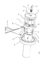
- the mechanically-adjustable pitch propeller (2) is axially attached on a propeller shaft (1).
- the propeller shaft (1) is driven by an engine (not shown in the figures) of a marine vessel connected thereto. Threads (1.1) are formed along a certain length on an end portion of the propeller shaft (1) and the propeller (2) is fixed to the shaft (1) after being fitted thereon by tightening of a nut (8) being placed on the threads (1.1) of the propeller shaft (1).
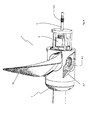
- the propeller (2) comprises a cylindrical hub (3) and a plurality of blades (10) extending radially outwardly from the hub (3).
- the hub (3) comprises a front end (3.4) and a rear end (3.5) and an open cavity (3.1) formed along the axis thereof.
- the cross section of the hub cavity (3.1) preferably comprises a cornered geometry such as a pentagon, hexagon, square etc. along almost the entire axis thereof.
- the cross sectional geometry on an end (3.5) portion of the hub cavity (3.1) is partially circular and a cross sectional narrowing takes place when being advanced from the circular cross section to the cross section with cornered geometry.
- the cross sectional narrowing defines an abutting surface (3.7) for the actuator (4) to be described later.
- the hub (3) comprises a plurality of blade connection openings (3.3) formed circularly along the hub thickness in the radial direction.
- Blade seating surfaces (3.2) are formed around each of the blade connection openings (3.3). Said blade seating surfaces (3.2) start from the external surface of the hub (3) and partially extend radially inwardly.
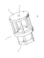
- the actuator (4) moving linearly in the direction of the axis of the hub (3) is placed partially into the hub cavity (3.1).
- the actuator (4) has a longitudinal form and comprises longitudinal actuator advancing surfaces (4.1) entering into the hub cavity (3.1).
- the cross sectional geometry of the actuator advancing surfaces (4.1) are compatible with the cross sectional geometry of the hub cavity (3.1). Namely, the cross sectional geometry of the actuator advancing surfaces (4.1) also comprises preferably a cornered geometry such as a pentagon, hexagon, square etc. In this situation, the actuator advancing surfaces (4.1) cooperates with the hub interior cavity surfaces (3.6). However, in terms of dimensions, the cross section of the actuator advancing surfaces (4.1) are made slightly smaller than the cross section of the hub cavity (3.1) such that the linear advancing of the actuator (4) inside the hub (3) can be possible.
- the inner portion of the actuator (4) comprises a cavity having a circular cross section along the axis thereof.
- the inner surface (4.8) of the actuator (4) is dimensioned so as to sit on the propeller shaft (1) and to linearly move thereon.
- Actuator slots (4.2) arranged circularly in the radial direction and formed so as to have the same number with the blades are disposed on the advancing surfaces (4.1) of the actuator. Motion transmission pins (10.3) to be described later are fitted in the slots (4.2).
- the actuator comprises an actuator flange (4.3) protruding radially outwardly on the other end thereof, i.e. where no slots (4.2) are formed.
- the actuator flange (4.3) is placed inside the circular cross section of the hub cavity (3.1) and preferably abuts to the abutting surface (3.7) at a maximum advancing position of the actuator (4).
- the actuator (4) further comprises rods (4.4) extending from the actuator flange (4.3) towards the other end thereof and an actuator disc (4.6) connected to said rods (4.4).
- Rod connection slots (4.5) are formed on the actuator flange (4.3) as well as the actuator disc (4.6) for the connection of the rods (4.4).
- the rods (4.4) are provided with circular form, wherein a cavity is disposed in the middle portion thereof such that the propeller connection nut (8) is placed into said cavity.
- a hole (4.7) is formed in the center of the actuator disc (4.6).
- a shaft (5) is supported at the hole (4.7) through the end portion thereof. Said support is a clearance fit, i.e. the shaft (5) can rotate relative to the actuator disc (4.6).
- various measures can be taken to avoid axial displacement of the shaft (5) inside the hole. For example, a circumferential diameter can be formed on the circular surfaces of the shaft remaining right outside the hole (4.7) and rings (12) can be placed into these slots.
- Threads (5.1) are axially formed along a certain length on the other end of the shaft (5).
- a wrench groove (5.2) extending axially inwardly from the threaded end portion of the shaft (5) is formed.
- the wrench groove (5.2) can be provided with a form so as to be rotated with for example an allen wrench.
- a conical piece (9) having a gradually tapering form for proper flow of the water leaving the propeller (2) is fixed on the rear end (3.5) portion of the hub.
- the inner portion of the conical piece (9) comprises a cavity so as to receive the actuator disc (4.6), rods (4.4), propeller connection nut (8) and respective portion of the propeller shaft (1).
- the conical piece (9) also comprises a circular shaft cavity (9.3) extending axially starting from the pointed end portion thereof. Screw threads (9.2) are formed along a certain length on the shaft cavity (9.3).
- the screw threads (9.2) of the conical piece are compatible with the shaft threads (5.1) so as to work together.
- a wrench hole (9.1) is formed on the tapered end portion of the conical piece (9).
- Each blade (10) comprises a blade-hub connection end (10.1) connected to the hub (3).
- the lower surfaces of the blade-hub connection ends (10.1) seat on the blade seating surfaces (3.2) formed on the hub (3).
- this is not a form-fitting seating, i.e. it is a loose seating, because, as will be described later, the blades (10) should be seated with a clearance so as to be rotated in their radial direction relative to the hub axis.
- a motion transmission means (10.2) is provided in the lower portion of each blade-hub connection end (10.1) so as to be disposed on the blade connection opening (3.3).
- the motion transmission means (10.2) have preferably a disc-like form and there is provided a bolt slot (10.5) at the center thereof. There is also provided a bolt slot (10.6) in the lower portion of each blade (10).
- the bolt (10.8) is preferably an allen type of bolt and after the bolt slots (10.5, 10.6) are aligned, the allen bolt (10.8) is inserted into the hub (3) and then tightened by means of an allen wrench.
- the blade and hub connection can be additionally streneghtened by using additional bolts (10.9) as shown in Figure 5 .
- Each of the motion transmission means (10.2) in the form of a disc comprises a motion transmission pin (10.3) disposed at a certain distance from the center thereof and extending in the axial direction therefrom.
- Each of the motion transmission pin (10.3) is shaped so as to be received by the respective slot (4.2) formed on the advancing surfaces (4.1) of the actuator.
- each motion transmission pin (10.3) disposed in the actuator slot (4.2) is pushed to rotate a certain amount about the axis of the motion transmission means (10.2).
- the disc shaped motion transmission means (10.2) also rotates a certain amount about the axis thereof; because, the motion transmission means (10.2) is not rigidly connected to the hub (3), i.e. the motion transmission means (10.2) is movable relative to the hub (3).
- the motion transmission means (10.2) is rotatably disposed inside a cavity formed inside the hub (3) (blade connection opening).
- each motion transmission means (10.2) is rigidly connected to the respective blade, when the motion transmission means (10.2) rotates, the blade (10) connected thereto also rotates about an axis radial to the axis of the hub (3).
- the pitch of the blades (10) can be manually adjusted as desired by means of a wrench (11).
- a cylindrical projection (10.7) extending downward from the hub connection end (10.1) of each blade is provided.
- a protrusion extending upward from the motion transmission means (10.2) fits inside the cavity of said projection (10.7).
- An O-ring (10.4) is disposed around the blade connection end projection (10.7).
- the mechanically-adjustable pitch propeller can be designed so as to be adapted to the already existing propeller shafts.
- a shaft sleeve (6) is coaxially fitted on the propeller shaft (1).
- the shaft sleeve (6) comprises a flange (6.2) at one of its end and a staged cylinder (6.1) extending axially therefrom.
- the diameter of the first stage (6.1.1) of the shaft sleeve cylinder is greater than the diameter of the second stage (6.1.2) thereof.
- the outer diameter of the second stage (6.1.2) of the cylinder is slightly smaller than the diameter of the circular inner surface (4.8) of the actuator (4), thus, when the actuator (4) is seated on the second cylinder stage (6.1.2), it can move linearly thereon.
- the outer diameter of the shaft sleeve flange (6.2) is substantially same as the outer diameter size of the hub (3).
- a static balance disc (7) is mounted on the propeller shaft (1) so as to correspond to the other end of the shaft sleeve flange (6.2).
- the static balance disc comprises disc connection holes (7.1) formed axially along the thickness thereof.
- connection elements such as bolts.
- the static balance disc (7) can be used to eliminate any possible mass imbalances of the propeller hub (3) or blades (10), which may occur due to manufacturing defects. In this case, the unbalanced mass is balanced by a mass (counter weight) against the static balance disc (7).
Landscapes
- Engineering & Computer Science (AREA)
- Chemical & Material Sciences (AREA)
- Combustion & Propulsion (AREA)
- Mechanical Engineering (AREA)
- Ocean & Marine Engineering (AREA)
- Aviation & Aerospace Engineering (AREA)
- Structures Of Non-Positive Displacement Pumps (AREA)
- Mixers Of The Rotary Stirring Type (AREA)
Applications Claiming Priority (1)
| Application Number | Priority Date | Filing Date | Title |
|---|---|---|---|
| TR201309329 | 2013-08-01 |
Publications (2)
| Publication Number | Publication Date |
|---|---|
| EP2832633A1 true EP2832633A1 (fr) | 2015-02-04 |
| EP2832633B1 EP2832633B1 (fr) | 2016-04-06 |
Family
ID=50000763
Family Applications (1)
| Application Number | Title | Priority Date | Filing Date |
|---|---|---|---|
| EP14000218.9A Active EP2832633B1 (fr) | 2013-08-01 | 2014-01-22 | Hélice à pas mécaniquement réglable |
Country Status (2)
| Country | Link |
|---|---|
| US (1) | US9611020B2 (fr) |
| EP (1) | EP2832633B1 (fr) |
Cited By (1)
| Publication number | Priority date | Publication date | Assignee | Title |
|---|---|---|---|---|
| CN114954874A (zh) * | 2022-07-07 | 2022-08-30 | 上海交通大学 | 应用鱼鳞仿生结构的可调螺距螺旋桨 |
Families Citing this family (4)
| Publication number | Priority date | Publication date | Assignee | Title |
|---|---|---|---|---|
| CN107725476B (zh) * | 2017-09-27 | 2019-03-05 | 江苏科技大学海洋装备研究院 | 一种叶片部分可调节式喷水推进器 |
| US11602825B2 (en) | 2017-12-13 | 2023-03-14 | Mike L. Roller | Boat propeller wrench with embedded metallic motor nut fastener |
| US12275514B1 (en) | 2023-09-22 | 2025-04-15 | Rolls-Royce Marine North America Inc. | Electrically controllable pitch propeller system for maritime crafts |
| US20250116164A1 (en) | 2023-10-10 | 2025-04-10 | Saudi Arabian Oil Company | Downhole robot for oil wells |
Citations (4)
| Publication number | Priority date | Publication date | Assignee | Title |
|---|---|---|---|---|
| US2620040A (en) * | 1948-01-19 | 1952-12-02 | Harry J Nichols | Controllable reversible pitch propeller |
| US3676016A (en) * | 1970-09-21 | 1972-07-11 | Arne Feroy | Controllable pitch propellers |
| FR2567096A1 (fr) * | 1984-07-04 | 1986-01-10 | Durand Francois | Mecanisme pour commande d'orientation de pales d'helice de navire |
| US4810166A (en) * | 1987-08-03 | 1989-03-07 | Bird-Johnson Company | Controllable pitch marine propeller |
Family Cites Families (7)
| Publication number | Priority date | Publication date | Assignee | Title |
|---|---|---|---|---|
| US3295610A (en) | 1965-10-24 | 1967-01-03 | Frias Robert | Automatic propeller pitch control and adaptor |
| US3497306A (en) | 1968-07-11 | 1970-02-24 | Adrian Phillips | Automatic variable pitch propeller |
| US4538962A (en) | 1984-01-24 | 1985-09-03 | Mccain Conrad L | Marine propeller lock |
| US5145318A (en) * | 1989-11-16 | 1992-09-08 | Bird-Johnson Company | Flange-mounted controllable pitch marine propeller |
| DE19936951C2 (de) | 1999-08-05 | 2001-08-23 | Peter Mueller | Verstellpropeller für Sportboote und Sportjachten |
| SE533034C2 (sv) * | 2008-09-17 | 2010-06-15 | Berg Propulsion Technology | Propeller |
| WO2010044733A1 (fr) * | 2008-10-16 | 2010-04-22 | Rolls-Royce Aktiebolag | Procédé et agencement de commande de pas d'hélice |
-
2013
- 2013-09-20 US US14/033,064 patent/US9611020B2/en not_active Expired - Fee Related
-
2014
- 2014-01-22 EP EP14000218.9A patent/EP2832633B1/fr active Active
Patent Citations (4)
| Publication number | Priority date | Publication date | Assignee | Title |
|---|---|---|---|---|
| US2620040A (en) * | 1948-01-19 | 1952-12-02 | Harry J Nichols | Controllable reversible pitch propeller |
| US3676016A (en) * | 1970-09-21 | 1972-07-11 | Arne Feroy | Controllable pitch propellers |
| FR2567096A1 (fr) * | 1984-07-04 | 1986-01-10 | Durand Francois | Mecanisme pour commande d'orientation de pales d'helice de navire |
| US4810166A (en) * | 1987-08-03 | 1989-03-07 | Bird-Johnson Company | Controllable pitch marine propeller |
Cited By (1)
| Publication number | Priority date | Publication date | Assignee | Title |
|---|---|---|---|---|
| CN114954874A (zh) * | 2022-07-07 | 2022-08-30 | 上海交通大学 | 应用鱼鳞仿生结构的可调螺距螺旋桨 |
Also Published As
| Publication number | Publication date |
|---|---|
| EP2832633B1 (fr) | 2016-04-06 |
| US9611020B2 (en) | 2017-04-04 |
| US20150037152A1 (en) | 2015-02-05 |
Similar Documents
| Publication | Publication Date | Title |
|---|---|---|
| US9611020B2 (en) | Mechanically-adjustable pitch propeller | |
| US20160009373A1 (en) | Variable Blade Pitch Propeller Assembly | |
| US5286166A (en) | Automatic centrifugal force variable pitch propeller | |
| CA2934614C (fr) | Ensemble de moyeu et assemblages d'helice | |
| US3308889A (en) | Variable pitch propeller with automatic adjustment | |
| EP2857307B1 (fr) | Hélice à pas réglable | |
| US3145780A (en) | Variable pitch propeller | |
| US9567049B2 (en) | Self-adjustable pitch propeller | |
| WO1990011221A1 (fr) | Helice a pas variable reglable manuellement | |
| US4778344A (en) | Variable pitch mechanisms | |
| EP3461735B1 (fr) | Hélice de survoltage de couple unidirectionnel | |
| US2379302A (en) | Variable pitch propeller | |
| EP2962931B1 (fr) | Dispositif à hélice d'amplification de couple | |
| US9533745B2 (en) | Feathering propeller with adjustable abutment | |
| US4179241A (en) | Full feathering, reversible pitch, constant RPM propeller | |
| US4704067A (en) | Helicoidal propeller pitch control mechanism | |
| CN115071957B (zh) | 一种可自动调螺距螺旋桨调节组件及装配方法 | |
| EP2593359B1 (fr) | Hélice à pas contrôlable avec amortissement des pales pendant la navigation avant et arrière et contrôle du pas des pales pendant la navigation arrière | |
| EP3293422B1 (fr) | Agencement de montage pour boîte de vitesses | |
| CN109803885B (zh) | 用于船舶的推进器和将桨毂帽安装至桨毂的方法 | |
| CN210479010U (zh) | 一种具有可调式高效气动力螺旋桨 | |
| WO2010059071A1 (fr) | Moyeu d'helice a pas commande pourvu d'un mecanisme de mise en drapeau automatique des pales | |
| US2528236A (en) | Aircraft propulsion unit | |
| WO2017178061A1 (fr) | Hélice pour navire et procédé d'installation de chapeau de moyeu sur le moyeu | |
| US1847180A (en) | Variable pitch propeller |
Legal Events
| Date | Code | Title | Description |
|---|---|---|---|
| 17P | Request for examination filed |
Effective date: 20140122 |
|
| AK | Designated contracting states |
Kind code of ref document: A1 Designated state(s): AL AT BE BG CH CY CZ DE DK EE ES FI FR GB GR HR HU IE IS IT LI LT LU LV MC MK MT NL NO PL PT RO RS SE SI SK SM TR |
|
| AX | Request for extension of the european patent |
Extension state: BA ME |
|
| PUAI | Public reference made under article 153(3) epc to a published international application that has entered the european phase |
Free format text: ORIGINAL CODE: 0009012 |
|
| R17P | Request for examination filed (corrected) |
Effective date: 20150311 |
|
| 17Q | First examination report despatched |
Effective date: 20150630 |
|
| RAP1 | Party data changed (applicant data changed or rights of an application transferred) |
Owner name: UELGEN, MEHMET, NEVRES |
|
| RIN1 | Information on inventor provided before grant (corrected) |
Inventor name: UELGEN, MEHMET, NEVRES |
|
| GRAP | Despatch of communication of intention to grant a patent |
Free format text: ORIGINAL CODE: EPIDOSNIGR1 |
|
| RAP1 | Party data changed (applicant data changed or rights of an application transferred) |
Owner name: UELGEN, MEHMET, NEVRES |
|
| RIN1 | Information on inventor provided before grant (corrected) |
Inventor name: UELGEN, MEHMET, NEVRES |
|
| INTG | Intention to grant announced |
Effective date: 20151223 |
|
| GRAS | Grant fee paid |
Free format text: ORIGINAL CODE: EPIDOSNIGR3 |
|
| GRAA | (expected) grant |
Free format text: ORIGINAL CODE: 0009210 |
|
| AK | Designated contracting states |
Kind code of ref document: B1 Designated state(s): AL AT BE BG CH CY CZ DE DK EE ES FI FR GB GR HR HU IE IS IT LI LT LU LV MC MK MT NL NO PL PT RO RS SE SI SK SM TR |
|
| REG | Reference to a national code |
Ref country code: GB Ref legal event code: FG4D |
|
| REG | Reference to a national code |
Ref country code: AT Ref legal event code: REF Ref document number: 787482 Country of ref document: AT Kind code of ref document: T Effective date: 20160415 Ref country code: CH Ref legal event code: EP |
|
| REG | Reference to a national code |
Ref country code: IE Ref legal event code: FG4D |
|
| REG | Reference to a national code |
Ref country code: DE Ref legal event code: R096 Ref document number: 602014001301 Country of ref document: DE |
|
| REG | Reference to a national code |
Ref country code: NL Ref legal event code: FP |
|
| REG | Reference to a national code |
Ref country code: LT Ref legal event code: MG4D |
|
| REG | Reference to a national code |
Ref country code: AT Ref legal event code: MK05 Ref document number: 787482 Country of ref document: AT Kind code of ref document: T Effective date: 20160406 |
|
| PG25 | Lapsed in a contracting state [announced via postgrant information from national office to epo] |
Ref country code: NO Free format text: LAPSE BECAUSE OF FAILURE TO SUBMIT A TRANSLATION OF THE DESCRIPTION OR TO PAY THE FEE WITHIN THE PRESCRIBED TIME-LIMIT Effective date: 20160706 Ref country code: FI Free format text: LAPSE BECAUSE OF FAILURE TO SUBMIT A TRANSLATION OF THE DESCRIPTION OR TO PAY THE FEE WITHIN THE PRESCRIBED TIME-LIMIT Effective date: 20160406 Ref country code: PL Free format text: LAPSE BECAUSE OF FAILURE TO SUBMIT A TRANSLATION OF THE DESCRIPTION OR TO PAY THE FEE WITHIN THE PRESCRIBED TIME-LIMIT Effective date: 20160406 Ref country code: IS Free format text: LAPSE BECAUSE OF FAILURE TO SUBMIT A TRANSLATION OF THE DESCRIPTION OR TO PAY THE FEE WITHIN THE PRESCRIBED TIME-LIMIT Effective date: 20160806 Ref country code: LT Free format text: LAPSE BECAUSE OF FAILURE TO SUBMIT A TRANSLATION OF THE DESCRIPTION OR TO PAY THE FEE WITHIN THE PRESCRIBED TIME-LIMIT Effective date: 20160406 |
|
| PG25 | Lapsed in a contracting state [announced via postgrant information from national office to epo] |
Ref country code: GR Free format text: LAPSE BECAUSE OF FAILURE TO SUBMIT A TRANSLATION OF THE DESCRIPTION OR TO PAY THE FEE WITHIN THE PRESCRIBED TIME-LIMIT Effective date: 20160707 Ref country code: HR Free format text: LAPSE BECAUSE OF FAILURE TO SUBMIT A TRANSLATION OF THE DESCRIPTION OR TO PAY THE FEE WITHIN THE PRESCRIBED TIME-LIMIT Effective date: 20160406 Ref country code: PT Free format text: LAPSE BECAUSE OF FAILURE TO SUBMIT A TRANSLATION OF THE DESCRIPTION OR TO PAY THE FEE WITHIN THE PRESCRIBED TIME-LIMIT Effective date: 20160808 Ref country code: SE Free format text: LAPSE BECAUSE OF FAILURE TO SUBMIT A TRANSLATION OF THE DESCRIPTION OR TO PAY THE FEE WITHIN THE PRESCRIBED TIME-LIMIT Effective date: 20160406 Ref country code: ES Free format text: LAPSE BECAUSE OF FAILURE TO SUBMIT A TRANSLATION OF THE DESCRIPTION OR TO PAY THE FEE WITHIN THE PRESCRIBED TIME-LIMIT Effective date: 20160406 Ref country code: RS Free format text: LAPSE BECAUSE OF FAILURE TO SUBMIT A TRANSLATION OF THE DESCRIPTION OR TO PAY THE FEE WITHIN THE PRESCRIBED TIME-LIMIT Effective date: 20160406 Ref country code: AT Free format text: LAPSE BECAUSE OF FAILURE TO SUBMIT A TRANSLATION OF THE DESCRIPTION OR TO PAY THE FEE WITHIN THE PRESCRIBED TIME-LIMIT Effective date: 20160406 Ref country code: LV Free format text: LAPSE BECAUSE OF FAILURE TO SUBMIT A TRANSLATION OF THE DESCRIPTION OR TO PAY THE FEE WITHIN THE PRESCRIBED TIME-LIMIT Effective date: 20160406 |
|
| PG25 | Lapsed in a contracting state [announced via postgrant information from national office to epo] |
Ref country code: BE Free format text: LAPSE BECAUSE OF FAILURE TO SUBMIT A TRANSLATION OF THE DESCRIPTION OR TO PAY THE FEE WITHIN THE PRESCRIBED TIME-LIMIT Effective date: 20160406 |
|
| REG | Reference to a national code |
Ref country code: DE Ref legal event code: R097 Ref document number: 602014001301 Country of ref document: DE |
|
| REG | Reference to a national code |
Ref country code: FR Ref legal event code: PLFP Year of fee payment: 4 |
|
| PG25 | Lapsed in a contracting state [announced via postgrant information from national office to epo] |
Ref country code: EE Free format text: LAPSE BECAUSE OF FAILURE TO SUBMIT A TRANSLATION OF THE DESCRIPTION OR TO PAY THE FEE WITHIN THE PRESCRIBED TIME-LIMIT Effective date: 20160406 Ref country code: CZ Free format text: LAPSE BECAUSE OF FAILURE TO SUBMIT A TRANSLATION OF THE DESCRIPTION OR TO PAY THE FEE WITHIN THE PRESCRIBED TIME-LIMIT Effective date: 20160406 Ref country code: RO Free format text: LAPSE BECAUSE OF FAILURE TO SUBMIT A TRANSLATION OF THE DESCRIPTION OR TO PAY THE FEE WITHIN THE PRESCRIBED TIME-LIMIT Effective date: 20160406 Ref country code: DK Free format text: LAPSE BECAUSE OF FAILURE TO SUBMIT A TRANSLATION OF THE DESCRIPTION OR TO PAY THE FEE WITHIN THE PRESCRIBED TIME-LIMIT Effective date: 20160406 Ref country code: SK Free format text: LAPSE BECAUSE OF FAILURE TO SUBMIT A TRANSLATION OF THE DESCRIPTION OR TO PAY THE FEE WITHIN THE PRESCRIBED TIME-LIMIT Effective date: 20160406 |
|
| PLBE | No opposition filed within time limit |
Free format text: ORIGINAL CODE: 0009261 |
|
| STAA | Information on the status of an ep patent application or granted ep patent |
Free format text: STATUS: NO OPPOSITION FILED WITHIN TIME LIMIT |
|
| PG25 | Lapsed in a contracting state [announced via postgrant information from national office to epo] |
Ref country code: SM Free format text: LAPSE BECAUSE OF FAILURE TO SUBMIT A TRANSLATION OF THE DESCRIPTION OR TO PAY THE FEE WITHIN THE PRESCRIBED TIME-LIMIT Effective date: 20160406 |
|
| 26N | No opposition filed |
Effective date: 20170110 |
|
| PG25 | Lapsed in a contracting state [announced via postgrant information from national office to epo] |
Ref country code: SI Free format text: LAPSE BECAUSE OF FAILURE TO SUBMIT A TRANSLATION OF THE DESCRIPTION OR TO PAY THE FEE WITHIN THE PRESCRIBED TIME-LIMIT Effective date: 20160406 |
|
| REG | Reference to a national code |
Ref country code: CH Ref legal event code: PL |
|
| PG25 | Lapsed in a contracting state [announced via postgrant information from national office to epo] |
Ref country code: MC Free format text: LAPSE BECAUSE OF FAILURE TO SUBMIT A TRANSLATION OF THE DESCRIPTION OR TO PAY THE FEE WITHIN THE PRESCRIBED TIME-LIMIT Effective date: 20160406 |
|
| PG25 | Lapsed in a contracting state [announced via postgrant information from national office to epo] |
Ref country code: LI Free format text: LAPSE BECAUSE OF NON-PAYMENT OF DUE FEES Effective date: 20170131 Ref country code: CH Free format text: LAPSE BECAUSE OF NON-PAYMENT OF DUE FEES Effective date: 20170131 |
|
| REG | Reference to a national code |
Ref country code: IE Ref legal event code: MM4A |
|
| REG | Reference to a national code |
Ref country code: FR Ref legal event code: PLFP Year of fee payment: 5 |
|
| PG25 | Lapsed in a contracting state [announced via postgrant information from national office to epo] |
Ref country code: LU Free format text: LAPSE BECAUSE OF NON-PAYMENT OF DUE FEES Effective date: 20170122 |
|
| PG25 | Lapsed in a contracting state [announced via postgrant information from national office to epo] |
Ref country code: IE Free format text: LAPSE BECAUSE OF NON-PAYMENT OF DUE FEES Effective date: 20170122 |
|
| PG25 | Lapsed in a contracting state [announced via postgrant information from national office to epo] |
Ref country code: MT Free format text: LAPSE BECAUSE OF NON-PAYMENT OF DUE FEES Effective date: 20170122 |
|
| PG25 | Lapsed in a contracting state [announced via postgrant information from national office to epo] |
Ref country code: AL Free format text: LAPSE BECAUSE OF FAILURE TO SUBMIT A TRANSLATION OF THE DESCRIPTION OR TO PAY THE FEE WITHIN THE PRESCRIBED TIME-LIMIT Effective date: 20160406 |
|
| PG25 | Lapsed in a contracting state [announced via postgrant information from national office to epo] |
Ref country code: HU Free format text: LAPSE BECAUSE OF FAILURE TO SUBMIT A TRANSLATION OF THE DESCRIPTION OR TO PAY THE FEE WITHIN THE PRESCRIBED TIME-LIMIT; INVALID AB INITIO Effective date: 20140122 |
|
| PG25 | Lapsed in a contracting state [announced via postgrant information from national office to epo] |
Ref country code: BG Free format text: LAPSE BECAUSE OF FAILURE TO SUBMIT A TRANSLATION OF THE DESCRIPTION OR TO PAY THE FEE WITHIN THE PRESCRIBED TIME-LIMIT Effective date: 20160406 |
|
| PG25 | Lapsed in a contracting state [announced via postgrant information from national office to epo] |
Ref country code: CY Free format text: LAPSE BECAUSE OF FAILURE TO SUBMIT A TRANSLATION OF THE DESCRIPTION OR TO PAY THE FEE WITHIN THE PRESCRIBED TIME-LIMIT Effective date: 20160406 |
|
| PG25 | Lapsed in a contracting state [announced via postgrant information from national office to epo] |
Ref country code: MK Free format text: LAPSE BECAUSE OF FAILURE TO SUBMIT A TRANSLATION OF THE DESCRIPTION OR TO PAY THE FEE WITHIN THE PRESCRIBED TIME-LIMIT Effective date: 20160406 |
|
| PGFP | Annual fee paid to national office [announced via postgrant information from national office to epo] |
Ref country code: DE Payment date: 20240326 Year of fee payment: 11 Ref country code: GB Payment date: 20240201 Year of fee payment: 11 |
|
| PGFP | Annual fee paid to national office [announced via postgrant information from national office to epo] |
Ref country code: TR Payment date: 20240318 Year of fee payment: 11 Ref country code: FR Payment date: 20240123 Year of fee payment: 11 |
|
| PGFP | Annual fee paid to national office [announced via postgrant information from national office to epo] |
Ref country code: IT Payment date: 20240424 Year of fee payment: 11 |
|
| PGFP | Annual fee paid to national office [announced via postgrant information from national office to epo] |
Ref country code: NL Payment date: 20240712 Year of fee payment: 11 |
|
| REG | Reference to a national code |
Ref country code: DE Ref legal event code: R119 Ref document number: 602014001301 Country of ref document: DE |
|
| REG | Reference to a national code |
Ref country code: NL Ref legal event code: MM Effective date: 20250201 |
|
| GBPC | Gb: european patent ceased through non-payment of renewal fee |
Effective date: 20250122 |
|
| PG25 | Lapsed in a contracting state [announced via postgrant information from national office to epo] |
Ref country code: DE Free format text: LAPSE BECAUSE OF NON-PAYMENT OF DUE FEES Effective date: 20250801 |
|
| PG25 | Lapsed in a contracting state [announced via postgrant information from national office to epo] |
Ref country code: NL Free format text: LAPSE BECAUSE OF NON-PAYMENT OF DUE FEES Effective date: 20250201 |
|
| PG25 | Lapsed in a contracting state [announced via postgrant information from national office to epo] |
Ref country code: GB Free format text: LAPSE BECAUSE OF NON-PAYMENT OF DUE FEES Effective date: 20250122 |
|
| PG25 | Lapsed in a contracting state [announced via postgrant information from national office to epo] |
Ref country code: FR Free format text: LAPSE BECAUSE OF NON-PAYMENT OF DUE FEES Effective date: 20250131 |
|
| PG25 | Lapsed in a contracting state [announced via postgrant information from national office to epo] |
Ref country code: IT Free format text: LAPSE BECAUSE OF NON-PAYMENT OF DUE FEES Effective date: 20250122 |