EP2832645A1 - Kraftstofftank, hauptflügel, flugzeugrumpf, flugzeug und mobiler körper - Google Patents
Kraftstofftank, hauptflügel, flugzeugrumpf, flugzeug und mobiler körper Download PDFInfo
- Publication number
- EP2832645A1 EP2832645A1 EP13769070.7A EP13769070A EP2832645A1 EP 2832645 A1 EP2832645 A1 EP 2832645A1 EP 13769070 A EP13769070 A EP 13769070A EP 2832645 A1 EP2832645 A1 EP 2832645A1
- Authority
- EP
- European Patent Office
- Prior art keywords
- fuel tank
- aircraft
- main wing
- structural member
- electrical conductivity
- Prior art date
- Legal status (The legal status is an assumption and is not a legal conclusion. Google has not performed a legal analysis and makes no representation as to the accuracy of the status listed.)
- Granted
Links
Images


Classifications
-
- B—PERFORMING OPERATIONS; TRANSPORTING
- B64—AIRCRAFT; AVIATION; COSMONAUTICS
- B64D—EQUIPMENT FOR FITTING IN OR TO AIRCRAFT; FLIGHT SUITS; PARACHUTES; ARRANGEMENT OR MOUNTING OF POWER PLANTS OR PROPULSION TRANSMISSIONS IN AIRCRAFT
- B64D37/00—Arrangements in connection with fuel supply for power plant
- B64D37/02—Tanks
- B64D37/04—Arrangement thereof in or on aircraft
-
- B—PERFORMING OPERATIONS; TRANSPORTING
- B64—AIRCRAFT; AVIATION; COSMONAUTICS
- B64C—AEROPLANES; HELICOPTERS
- B64C3/00—Wings
- B64C3/34—Tanks constructed integrally with wings, e.g. for fuel or water
-
- B—PERFORMING OPERATIONS; TRANSPORTING
- B60—VEHICLES IN GENERAL
- B60K—ARRANGEMENT OR MOUNTING OF PROPULSION UNITS OR OF TRANSMISSIONS IN VEHICLES; ARRANGEMENT OR MOUNTING OF PLURAL DIVERSE PRIME-MOVERS IN VEHICLES; AUXILIARY DRIVES FOR VEHICLES; INSTRUMENTATION OR DASHBOARDS FOR VEHICLES; ARRANGEMENTS IN CONNECTION WITH COOLING, AIR INTAKE, GAS EXHAUST OR FUEL SUPPLY OF PROPULSION UNITS IN VEHICLES
- B60K15/00—Arrangement in connection with fuel supply of combustion engines or other fuel consuming energy converters, e.g. fuel cells; Mounting or construction of fuel tanks
- B60K15/03—Fuel tanks
- B60K15/03177—Fuel tanks made of non-metallic material, e.g. plastics, or of a combination of non-metallic and metallic material
-
- B—PERFORMING OPERATIONS; TRANSPORTING
- B64—AIRCRAFT; AVIATION; COSMONAUTICS
- B64D—EQUIPMENT FOR FITTING IN OR TO AIRCRAFT; FLIGHT SUITS; PARACHUTES; ARRANGEMENT OR MOUNTING OF POWER PLANTS OR PROPULSION TRANSMISSIONS IN AIRCRAFT
- B64D37/00—Arrangements in connection with fuel supply for power plant
- B64D37/02—Tanks
-
- B—PERFORMING OPERATIONS; TRANSPORTING
- B64—AIRCRAFT; AVIATION; COSMONAUTICS
- B64D—EQUIPMENT FOR FITTING IN OR TO AIRCRAFT; FLIGHT SUITS; PARACHUTES; ARRANGEMENT OR MOUNTING OF POWER PLANTS OR PROPULSION TRANSMISSIONS IN AIRCRAFT
- B64D37/00—Arrangements in connection with fuel supply for power plant
- B64D37/02—Tanks
- B64D37/06—Constructional adaptations thereof
- B64D37/08—Internal partitioning
-
- Y—GENERAL TAGGING OF NEW TECHNOLOGICAL DEVELOPMENTS; GENERAL TAGGING OF CROSS-SECTIONAL TECHNOLOGIES SPANNING OVER SEVERAL SECTIONS OF THE IPC; TECHNICAL SUBJECTS COVERED BY FORMER USPC CROSS-REFERENCE ART COLLECTIONS [XRACs] AND DIGESTS
- Y02—TECHNOLOGIES OR APPLICATIONS FOR MITIGATION OR ADAPTATION AGAINST CLIMATE CHANGE
- Y02T—CLIMATE CHANGE MITIGATION TECHNOLOGIES RELATED TO TRANSPORTATION
- Y02T50/00—Aeronautics or air transport
- Y02T50/40—Weight reduction
Definitions
- the present invention relates to a fuel tank using carbon fiber reinforced plastic as a structural member thereof, a main wing, an aircraft fuselage, an aircraft, and a mobile body.
- a main wing of an aircraft is used as a fuel tank capable of accommodating fuel.
- a fuel tank integrated with the main wing and having a wing structure of a liquid-tight structure in which oil does not leak is called an integral tank.
- the integral tank has a tendency to apply a composite material, for example, carbon fiber reinforced plastic (CFRP) thereto for the purpose of weight reduction.
- CFRP carbon fiber reinforced plastic
- CFRP carbon fibers are used as reinforcing materials and synthetic resin is used as a matrix.
- a technique which is an invention relating to a three-dimensional fiber-reinforced resin composite material and in which a selvage warp is configured by an electrically-conductive material having higher electrical conductivity than an in-plane direction yarn in order to apply electrical conductivity to a fiber-reinforced resin composite material without impairing productivity.
- a technique which is an invention relating to a prepreg and a carbon fiber reinforced composite material and includes electrically-conductive particles or fibers therein for the purpose of having both excellent impact resistance and electrical conductivity.
- a technique is disclosed which is an invention relating to an improved composite material and includes electrically-conductive particles dispersed in polymeric resin therein for the purpose of having electrical conductivity and causing little or no weight increase compared to a standard composite material.
- the above-described problem is not limited to the integral tank integrated with the main wing of an aircraft and also occurs in a container of a fuel cell through which fuel flows.
- the fuel cell container as being included in the fuel tank as well.
- the same problem also occurs in a fuselage of an aircraft having a fuel tank, and a mobile body such as an automobile with a fuel tank mounted thereon other than an aircraft.
- the present invention has been made in view of such circumstances and has an object to provide a fuel tank in which it is possible to reduce working hours or cost in a manufacturing process and prevent an increase in weight in, a main wing, an aircraft fuselage, an aircraft, and a mobile body.
- a fuel tank, a main wing, an aircraft fuselage, an aircraft, and a mobile body according to the present invention adopt the following means.
- a fuel tank according to the present invention includes a structural member using carbon fiber reinforced plastic in which a reinforcing material includes carbon fibers and a matrix includes plastic, wherein the matrix has electrical conductivity applied thereto.
- the structural member of the fuel tank is the carbon fiber reinforced plastic in which the reinforcing material includes carbon fibers.
- the matrix of the carbon fiber reinforced plastic includes plastic and has electrical conductivity applied thereto.
- electrical conductivity is not applied to the matrix and treatment of a sealant or the like is not carried out on an end portion of the structural member, if a lightning current flows through the end portion at the time of a lightning strike, there is a concern that electric discharge may occur between the reinforcing materials at the end portion.
- electrical conductivity is applied to the matrix, electrical conduction between the reinforcing materials that are carbon fibers is secured, and thus the occurrence of electric discharge in the end portion of the structural member can be prevented.
- a cut surface of the structural member which is formed by cutting the structural member, may be exposed to an inside in which fuel is accommodated.
- the carbon fiber reinforced plastic have a resistivity in a plate thickness direction of less than or equal to 500 ⁇ cm.
- a main wing according to the present invention has the above-described fuel tank as a structural body thereof, and an aircraft fuselage according to the present invention includes the above-described fuel tank.
- the structural body of the main wing is the fuel tank, or the aircraft fuselage is provided with the fuel tank, and the structural member of the fuel tank is the carbon fiber reinforced plastic. Then, since the matrix of the carbon fiber reinforced plastic includes plastic and has electrical conductivity applied thereto, electrical conduction between the reinforcing materials which include carbon fibers is secured, and thus the occurrence of electric discharge in the end portion of the structural member can be prevented.
- an aircraft according to the present invention includes the above-described main wing or the above-described aircraft fuselage.
- the main wing of the aircraft or the aircraft fuselage has the fuel tank as a structural body thereof and the structural member of the fuel tank is the carbon fiber reinforced plastic. Then, since the matrix of the carbon fiber reinforced plastic includes plastic and has electrical conductivity applied thereto, electrical conduction between the reinforcing materials which include carbon fibers is secured, and thus the occurrence of electric discharge in the end portion of the structural member can be prevented.
- a mobile body according to the present invention includes the above-described fuel tank.
- the mobile body has the fuel tank as a structural body thereof and the structural member of the fuel tank is the carbon fiber reinforced plastic. Then, since the matrix of the carbon fiber reinforced plastic includes plastic and has electrical conductivity applied thereto, electrical conduction between the reinforcing materials which include carbon fibers is secured, and thus the occurrence of electric discharge in the end portion of the structural member can be prevented.
- the present invention since electrical conductivity is applied to the matrix, electrical conduction between the reinforcing materials that are carbon fibers is secured, and thus the occurrence of electric discharge between the reinforcing materials in the end portion of the structural member can be prevented, and since a sealant or the like need not be separately provided at the end portion of the structural member, it is possible to reduce working hours or cost in a manufacturing process and prevent an increase in weight.
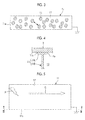
- the main wing 1 is provided with an upper skin 3, a lower skin 5, a front spar 7, a rear spar 9, a plurality of ribs 11, and the like, as shown in Figs. 1 and 2 .
- the upper skin 3 and the lower skin 5 are thin plates which configure the outer shape of the main wing 1 and also double as aerodynamic surfaces.
- the upper skin 3 and the lower skin 5 take charge of a portion of a tensile load or a compressive load acting on the main wing 1, along with the front spar 7, the rear spar 9, and a stringer (not shown).
- the front spar 7 and the rear spar 9 are structural members which are provided to extend in a wingspan direction of the main wing 1, as show in Fig. 1 , and are disposed between the upper skin 3 and the lower skin 5.
- a plurality of stringers are auxiliary members which are provided to extend in the wingspan direction of the main wing 1 on the internal surface of the upper skin 3 or the lower skin 5, and are disposed between the front spar 7 and the rear spar 9.
- the rib 11 is a structural member which is provided in a wingspread direction of the main wing 1, as shown in Fig. 1 , and is disposed between the upper skin 3 and the lower skin 5. That is, the rib 11 is a structural member which is provided to extend in a direction approximately orthogonal to the front spar 7 and the rear spar 9, and a plate-like member formed in a vertical cross-sectional shape of the main wing 1. In the rib 11, a plurality of openings 14 are formed in a longitudinal direction, as shown in Fig. 1 or 2 .
- a section surrounded by the front spar 7, the rear spar 9, the upper skin 3, and the lower skin 5 is used as a fuel tank 13 which accommodates fuel.
- a fuselage structure itself is regarded as a container, and thus the fuel tank 13 is called an integral tank.
- the front spar 7, the rear spar 9, the upper skin 3, the lower skin 5, and the rib 11 are also structural members of the fuel tank 13.
- the fuel tank 13 has a liquid-tight structure in which fuel does not leak to the outside.
- fuel piping for supplying the fuel to the fuel tank 13
- a plurality of fuel oil meters for detecting a fuel oil quantity
- wiring for the fuel oil meter, and the like are installed.
- CFRP carbon fiber reinforced plastic
- all of the front spar 7, the rear spar 9, the upper skin 3, the lower skin 5, and the rib 11 may not be formed of the CFRP and may be partially formed of metal such as an aluminum alloy.
- the matrix 17 includes plastic such as thermosetting resin such as unsaturated polyester or epoxy resin, for example.
- plastic such as thermosetting resin such as unsaturated polyester or epoxy resin
- electrical conductivity a variety of techniques to apply electrical conductivity to plastic such as thermosetting resin can be applied, and in this specification, detailed description thereof is omitted.
- electrical conductivity to the matrix 17 there is, for example, a method of including electrically-conductive particles or fibers in plastic, a method of applying electrical conductivity to plastic itself, or the like.
- the resistivity of the matrix 17 is, for example, several ⁇ cm.
- a cut surface formed by cutting work is exposed inside the fuel tank 13 in which fuel is accommodated.
- the rib 11 is configured to include a flange 11A, a web 11B, and the like, cut surfaces 11a are exposed to the inside of the fuel tank 13 at end portions of the flange 11A.
- the structural members of the fuel tank 13 are the CFRP in which the reinforcing material 15 includes carbon fibers, and the matrix 17 includes plastic and has electrical conductivity applied thereto. Since electrical conductivity is applied to the matrix 17, even if the cut surface 11a is exposed to the inside of the fuel tank 13, electrical conduction between the reinforcing materials 15 is secured, and thus the occurrence of electric discharge between the reinforcing materials 15 in the cut surface 11a of the structural member can be prevented.
- a test method of the lightning protection test was carried out according to the description of Conducted Current Test of Aircraft Lightning Test Method (ARP5416) of SAF International.
- the high-current waveform applied to the test body is a component A waveform of a simulated lightning current which is defined in ARP5412A.
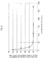
- Fig. 8 shows the relationship between a resistivity [ ⁇ cm] in a plate thickness direction of the test body and a relative spark generation current [%].
- a spark generation current value of each test body when a spark generation current value of the structural member having the CFRP with no electrical conductivity applied thereto is set to be 100% is shown at a percentage.
- the structural member having the CFRP with electrical conductivity applied thereto exhibits superiority in relative spark generation current, and in particular, if the resistivity in the plate thickness direction is less than or equal to about 200 ⁇ cm, it is found that the relative spark generation current becomes double or more.
- the embodiment described above has been described with regard to a case of the fuel tank 13 which is called an integral tank integrated with a main wing of an aircraft.
- the present invention is not limited to this example.
- the present invention can also be applied to, for example, a structural member which is used for a container (a fuel tank) of a fuel cell through which fuel flows.
- the present invention can also be applied to a structural member of a fuel tank which is installed in a fuselage of an aircraft or a structural member of a fuel tank which is mounted on a mobile body such as an automobile other than an aircraft.
Landscapes
- Engineering & Computer Science (AREA)
- Aviation & Aerospace Engineering (AREA)
- Mechanical Engineering (AREA)
- Chemical & Material Sciences (AREA)
- Sustainable Development (AREA)
- Sustainable Energy (AREA)
- Life Sciences & Earth Sciences (AREA)
- Combustion & Propulsion (AREA)
- Transportation (AREA)
- Cooling, Air Intake And Gas Exhaust, And Fuel Tank Arrangements In Propulsion Units (AREA)
- Moulding By Coating Moulds (AREA)
- Reinforced Plastic Materials (AREA)
- Laminated Bodies (AREA)
Applications Claiming Priority (2)
| Application Number | Priority Date | Filing Date | Title |
|---|---|---|---|
| JP2012069375 | 2012-03-26 | ||
| PCT/JP2013/057348 WO2013146335A1 (ja) | 2012-03-26 | 2013-03-15 | 燃料タンク、主翼、航空機胴体、航空機及び移動体 |
Publications (3)
| Publication Number | Publication Date |
|---|---|
| EP2832645A1 true EP2832645A1 (de) | 2015-02-04 |
| EP2832645A4 EP2832645A4 (de) | 2015-12-02 |
| EP2832645B1 EP2832645B1 (de) | 2023-03-08 |
Family
ID=49259597
Family Applications (1)
| Application Number | Title | Priority Date | Filing Date |
|---|---|---|---|
| EP13769070.7A Active EP2832645B1 (de) | 2012-03-26 | 2013-03-15 | Kraftstofftank, hauptflügel, flugzeugrumpf, flugzeug und mobiler körper |
Country Status (7)
| Country | Link |
|---|---|
| US (1) | US10011366B2 (de) |
| EP (1) | EP2832645B1 (de) |
| JP (1) | JP5972967B2 (de) |
| KR (1) | KR20140123972A (de) |
| CN (1) | CN104203752A (de) |
| RU (1) | RU2581104C1 (de) |
| WO (1) | WO2013146335A1 (de) |
Cited By (1)
| Publication number | Priority date | Publication date | Assignee | Title |
|---|---|---|---|---|
| EP3213989A1 (de) * | 2016-03-04 | 2017-09-06 | The Boeing Company | Leitfähiges radius-füllersystem und verfahren |
Families Citing this family (7)
| Publication number | Priority date | Publication date | Assignee | Title |
|---|---|---|---|---|
| JP6113544B2 (ja) * | 2013-03-26 | 2017-04-12 | 三菱重工業株式会社 | 燃料タンク、主翼、航空機胴体、航空機及び移動体 |
| JP6238168B2 (ja) * | 2014-02-04 | 2017-11-29 | 三菱重工業株式会社 | 複合材構造 |
| CN105221748A (zh) * | 2015-08-25 | 2016-01-06 | 中国航空工业集团公司西安飞机设计研究所 | 一种飞机整体油箱的密封方法 |
| KR101880055B1 (ko) | 2017-01-10 | 2018-07-20 | 한국항공우주산업 주식회사 | 항공기 날개 연료탱크용 격벽 |
| CN109131904A (zh) * | 2018-09-28 | 2019-01-04 | 成都飞机工业(集团)有限责任公司 | 一种抗冲击的飞机整体油箱 |
| CN110920913B (zh) * | 2019-12-04 | 2023-06-23 | 中国航空工业集团公司成都飞机设计研究所 | 一种大展弦比复合材料加筋壁板双油箱结构 |
| IT202300009465A1 (it) * | 2023-05-11 | 2024-11-11 | Leonardo Spa | Metodo di realizzazione di una struttura scatolata in materiale composito per aeromobili |
Family Cites Families (62)
| Publication number | Priority date | Publication date | Assignee | Title |
|---|---|---|---|---|
| US4169816A (en) * | 1978-03-06 | 1979-10-02 | Exxon Research & Engineering Co. | Electrically conductive polyolefin compositions |
| US4291816A (en) | 1980-07-09 | 1981-09-29 | Canadair Limited | Fuel tank access door for aircraft |
| US4352142A (en) | 1981-04-15 | 1982-09-28 | The Boeing Company | Composite aircraft structure having lightning protection |
| US4556591A (en) | 1981-09-25 | 1985-12-03 | The Boeing Company | Conductive bonded/bolted joint seals for composite aircraft |
| US4556439A (en) | 1981-09-25 | 1985-12-03 | The Boeing Company | Method of sealing and bonding laminated epoxy plates |
| US4556592A (en) | 1981-09-25 | 1985-12-03 | The Boeing Company | Conductive joint seals for composite aircraft |
| SU1362681A1 (ru) | 1986-04-10 | 1987-12-30 | Государственный научно-исследовательский институт гражданской авиации | Устройство дл молниезащиты внешних топливных баков летательного аппарата |
| US4755904A (en) | 1986-06-06 | 1988-07-05 | The Boeing Company | Lightning protection system for conductive composite material structure |
| JPH0263725A (ja) | 1988-05-27 | 1990-03-05 | Mitsubishi Heavy Ind Ltd | 炭素繊維強化プラスチツク部材の組立方法 |
| US6086975A (en) | 1991-01-16 | 2000-07-11 | The Boeing Company | Lighting protection for electrically conductive or insulating skin and core for honeycomb structure |
| US5332178A (en) | 1992-06-05 | 1994-07-26 | Williams International Corporation | Composite wing and manufacturing process thereof |
| JPH0616846A (ja) | 1992-07-03 | 1994-01-25 | Hitachi Zosen Corp | 導電性を有する繊維強化合成樹脂 |
| EP0629549A3 (de) | 1993-06-09 | 1995-03-08 | Inco Ltd | Verbundwerkstoff um Blitzeinschlägen zu Widerstehen, mit verbesserter elektrischer Leiterfähigkeit. |
| GB9419765D0 (en) | 1994-09-30 | 1994-11-16 | Symons Richard D | Storage of sensitive media |
| US5866272A (en) | 1996-01-11 | 1999-02-02 | The Boeing Company | Titanium-polymer hybrid laminates |
| GB9807198D0 (en) | 1998-04-04 | 1998-06-03 | British Aerospace | Adhesively bonded joints in carbon fibre composite structures |
| US6327132B1 (en) | 1998-06-10 | 2001-12-04 | Aerospatiale Matra | Spark resistant structure, in particular for aircraft |
| US6460721B2 (en) | 1999-03-23 | 2002-10-08 | Exxonmobil Upstream Research Company | Systems and methods for producing and storing pressurized liquefied natural gas |
| JP2001304492A (ja) | 2000-04-19 | 2001-10-31 | Mitsubishi Chemicals Corp | 耐圧容器 |
| RU2192991C2 (ru) | 2000-12-18 | 2002-11-20 | Открытое Акционерное Общество "Московский Вертолетный Завод Им. М.Л. Миля" | Способ защиты топливных баков вертолета от термического воздействия тока молнии |
| JP2003154591A (ja) | 2001-09-04 | 2003-05-27 | Toray Ind Inc | 繊維強化熱可塑性プラスチック |
| RU2217320C1 (ru) | 2002-03-14 | 2003-11-27 | Федеральное государственное унитарное предприятие "Всероссийский научно-исследовательский институт авиационных материалов" | Многослойное молниезащитное покрытие |
| US6910659B2 (en) | 2002-10-22 | 2005-06-28 | The Boeing Company | Method and apparatus for liquid containment, such as for aircraft fuel vessels |
| GB0329891D0 (en) | 2003-12-23 | 2004-01-28 | Airbus Uk Ltd | A sealing material |
| US20050175813A1 (en) | 2004-02-10 | 2005-08-11 | Wingert A. L. | Aluminum-fiber laminate |
| ES2279664B1 (es) | 2004-12-30 | 2008-08-01 | Airbus España S.L. | Dispositivo de proteccion contra descargas electricas en aeronaves. |
| JP3850427B2 (ja) | 2005-03-22 | 2006-11-29 | 株式会社物産ナノテク研究所 | 炭素繊維結合体およびこれを用いた複合材料 |
| US8231751B2 (en) | 2005-09-06 | 2012-07-31 | The Boeing Company | Repair technique for lightning strike protection |
| EP1996465A2 (de) | 2006-03-10 | 2008-12-03 | Goodrich Corporation | Schutz vor blitzschlägen von geringer dichte zur verwendung in flugzeugen |
| JP4972341B2 (ja) * | 2006-05-11 | 2012-07-11 | 富士重工業株式会社 | 3次元繊維強化樹脂複合材 |
| US20080012681A1 (en) * | 2006-05-26 | 2008-01-17 | Paul Kadar | Thermally protected electrical wiring device |
| JP4969363B2 (ja) | 2006-08-07 | 2012-07-04 | 東レ株式会社 | プリプレグおよび炭素繊維強化複合材料 |
| US8900496B2 (en) * | 2006-10-13 | 2014-12-02 | The Boeing Company | Edge seals for composite structure fuel tanks |
| GB0622060D0 (en) | 2006-11-06 | 2006-12-13 | Hexcel Composites Ltd | Improved composite materials |
| US7898785B2 (en) | 2006-12-07 | 2011-03-01 | The Boeing Company | Lightning protection system for an aircraft composite structure |
| US7599164B2 (en) | 2006-12-07 | 2009-10-06 | The Boeing Company | Lightning protection system for aircraft composite structure |
| US7934676B2 (en) | 2007-06-28 | 2011-05-03 | The Boeing Company | Pre-fabricated article for EME protection of an aircraft |
| EP2070974B1 (de) * | 2007-12-10 | 2014-02-12 | The Boeing Company | Metallimprägnierte Verbundwerkstoffe und Verfharen zu ihrer Herstellung |
| GB0803823D0 (en) | 2008-02-29 | 2008-04-09 | Victrex Mfg Ltd | Composite materials |
| US20090224102A1 (en) * | 2008-03-06 | 2009-09-10 | White Walter W | Aircraft Wing and Fuselage Structure |
| JP5055178B2 (ja) | 2008-03-24 | 2012-10-24 | 三菱重工業株式会社 | 航空機組立品 |
| RU2381242C2 (ru) | 2008-04-15 | 2010-02-10 | Институт химии и химической технологии СО РАН | Композиционный износостойкий материал на основе сверхвысокомолекулярного полиэтилена (свмпэ) |
| US20100107513A1 (en) | 2008-11-03 | 2010-05-06 | Buchanan Kenneth K | Pre-Cured Edge Seal |
| JP5155833B2 (ja) | 2008-12-01 | 2013-03-06 | 三菱重工業株式会社 | 航空機の燃料タンク |
| JP2010194749A (ja) | 2009-02-23 | 2010-09-09 | Mitsubishi Heavy Ind Ltd | 樹脂基複合材の製造方法 |
| ES2376323B1 (es) | 2009-02-27 | 2013-01-24 | Airbus Operations, S.L. | Mejora de la protección contra impacto directo de rayos en zonas remachadas de paneles en cfrp. |
| JP5101554B2 (ja) | 2009-03-30 | 2012-12-19 | 三菱重工業株式会社 | 航空機の燃料タンク |
| JP5237170B2 (ja) * | 2009-03-30 | 2013-07-17 | 三菱重工業株式会社 | 複合材タンク、翼、および、複合材タンクの製造方法 |
| GB0906686D0 (en) | 2009-04-20 | 2009-06-03 | Airbus Uk Ltd | Edge seal for fibre-reinforced composite structure |
| GB0912016D0 (en) * | 2009-07-10 | 2009-08-19 | Airbus Operations Ltd | Edge glow protection for composite component |
| JP5455541B2 (ja) * | 2009-10-14 | 2014-03-26 | 三菱重工業株式会社 | ストリンガーの製造方法 |
| KR101420155B1 (ko) | 2009-10-22 | 2014-07-16 | 알코아 인코포레이티드 | 전도도가 향상된 슬리브형 파스너 및 그 제조 방법 |
| GB201000878D0 (en) | 2010-01-20 | 2010-03-10 | Airbus Operations Ltd | Sandwich panel |
| JP2011213991A (ja) * | 2010-03-16 | 2011-10-27 | Toray Ind Inc | 炭素繊維強化複合材料 |
| JP5619446B2 (ja) | 2010-03-23 | 2014-11-05 | 三菱重工業株式会社 | キャップ、これを用いた締結構造およびこの締結構造を有する航空機 |
| RU2436688C1 (ru) | 2010-04-12 | 2011-12-20 | Нина Григорьевна Смирнова | Способ изготовления гибкого ударопрочного топливного бака |
| CN101984009B (zh) | 2010-10-26 | 2012-10-31 | 浙江大学 | 一种抗雷击导电涂料及其制备方法 |
| US9802714B2 (en) | 2010-12-03 | 2017-10-31 | The Boeing Company | Electric charge dissipation system for aircraft |
| JP5773679B2 (ja) | 2011-02-16 | 2015-09-02 | 三菱重工業株式会社 | 炭素繊維強化プラスチック構造体及びその製造方法 |
| JP5822493B2 (ja) | 2011-03-16 | 2015-11-24 | 三菱航空機株式会社 | 耐雷ファスナ、航空機組立品、航空機組立部品の製造方法 |
| US8882023B2 (en) | 2011-04-11 | 2014-11-11 | The Boeing Company | Aircraft structural assembly with electromagnetic protection |
| US20160229552A1 (en) | 2015-02-05 | 2016-08-11 | The Boeing Company | Intermetallic and composite metallic gap filler |
-
2013
- 2013-03-15 JP JP2014507684A patent/JP5972967B2/ja active Active
- 2013-03-15 RU RU2014133705/11A patent/RU2581104C1/ru active
- 2013-03-15 WO PCT/JP2013/057348 patent/WO2013146335A1/ja not_active Ceased
- 2013-03-15 CN CN201380014810.6A patent/CN104203752A/zh active Pending
- 2013-03-15 US US14/382,961 patent/US10011366B2/en active Active
- 2013-03-15 EP EP13769070.7A patent/EP2832645B1/de active Active
- 2013-03-15 KR KR1020147023846A patent/KR20140123972A/ko not_active Ceased
Cited By (2)
| Publication number | Priority date | Publication date | Assignee | Title |
|---|---|---|---|---|
| EP3213989A1 (de) * | 2016-03-04 | 2017-09-06 | The Boeing Company | Leitfähiges radius-füllersystem und verfahren |
| US10329030B2 (en) | 2016-03-04 | 2019-06-25 | The Boeing Company | Conductive radius filler system and method |
Also Published As
| Publication number | Publication date |
|---|---|
| JP5972967B2 (ja) | 2016-08-17 |
| KR20140123972A (ko) | 2014-10-23 |
| EP2832645A4 (de) | 2015-12-02 |
| WO2013146335A1 (ja) | 2013-10-03 |
| RU2581104C1 (ru) | 2016-04-10 |
| EP2832645B1 (de) | 2023-03-08 |
| US20150041592A1 (en) | 2015-02-12 |
| US10011366B2 (en) | 2018-07-03 |
| CN104203752A (zh) | 2014-12-10 |
| JPWO2013146335A1 (ja) | 2015-12-10 |
Similar Documents
| Publication | Publication Date | Title |
|---|---|---|
| US10011366B2 (en) | Fuel tank, main wing, aircraft fuselage, aircraft, and mobile body | |
| JP6113544B2 (ja) | 燃料タンク、主翼、航空機胴体、航空機及び移動体 | |
| US9776732B2 (en) | Structural material for structure, fuel tank, main wing, and aircraft | |
| EP2415693B1 (de) | Verbundtank, herstellungsverfahren dafür und flügel | |
| CA2752581C (en) | Aircraft fuel tank | |
| US10046849B2 (en) | Fuel tank, main wings, aircraft fuselage, aircraft, and moving body |
Legal Events
| Date | Code | Title | Description |
|---|---|---|---|
| PUAI | Public reference made under article 153(3) epc to a published international application that has entered the european phase |
Free format text: ORIGINAL CODE: 0009012 |
|
| 17P | Request for examination filed |
Effective date: 20140730 |
|
| AK | Designated contracting states |
Kind code of ref document: A1 Designated state(s): AL AT BE BG CH CY CZ DE DK EE ES FI FR GB GR HR HU IE IS IT LI LT LU LV MC MK MT NL NO PL PT RO RS SE SI SK SM TR |
|
| AX | Request for extension of the european patent |
Extension state: BA ME |
|
| DAX | Request for extension of the european patent (deleted) | ||
| RA4 | Supplementary search report drawn up and despatched (corrected) |
Effective date: 20151102 |
|
| RIC1 | Information provided on ipc code assigned before grant |
Ipc: B64D 37/02 20060101AFI20151027BHEP Ipc: B64C 3/34 20060101ALI20151027BHEP |
|
| STAA | Information on the status of an ep patent application or granted ep patent |
Free format text: STATUS: EXAMINATION IS IN PROGRESS |
|
| 17Q | First examination report despatched |
Effective date: 20180416 |
|
| GRAP | Despatch of communication of intention to grant a patent |
Free format text: ORIGINAL CODE: EPIDOSNIGR1 |
|
| STAA | Information on the status of an ep patent application or granted ep patent |
Free format text: STATUS: GRANT OF PATENT IS INTENDED |
|
| RIC1 | Information provided on ipc code assigned before grant |
Ipc: B64D 37/08 20060101ALI20220901BHEP Ipc: B64C 3/34 20060101ALI20220901BHEP Ipc: B64D 37/02 20060101AFI20220901BHEP |
|
| INTG | Intention to grant announced |
Effective date: 20220928 |
|
| GRAS | Grant fee paid |
Free format text: ORIGINAL CODE: EPIDOSNIGR3 |
|
| GRAA | (expected) grant |
Free format text: ORIGINAL CODE: 0009210 |
|
| STAA | Information on the status of an ep patent application or granted ep patent |
Free format text: STATUS: THE PATENT HAS BEEN GRANTED |
|
| AK | Designated contracting states |
Kind code of ref document: B1 Designated state(s): AL AT BE BG CH CY CZ DE DK EE ES FI FR GB GR HR HU IE IS IT LI LT LU LV MC MK MT NL NO PL PT RO RS SE SI SK SM TR |
|
| REG | Reference to a national code |
Ref country code: GB Ref legal event code: FG4D |
|
| REG | Reference to a national code |
Ref country code: CH Ref legal event code: EP Ref country code: AT Ref legal event code: REF Ref document number: 1552442 Country of ref document: AT Kind code of ref document: T Effective date: 20230315 |
|
| REG | Reference to a national code |
Ref country code: DE Ref legal event code: R096 Ref document number: 602013083416 Country of ref document: DE |
|
| REG | Reference to a national code |
Ref country code: IE Ref legal event code: FG4D |
|
| REG | Reference to a national code |
Ref country code: LT Ref legal event code: MG9D |
|
| REG | Reference to a national code |
Ref country code: NL Ref legal event code: MP Effective date: 20230308 |
|
| PG25 | Lapsed in a contracting state [announced via postgrant information from national office to epo] |
Ref country code: RS Free format text: LAPSE BECAUSE OF FAILURE TO SUBMIT A TRANSLATION OF THE DESCRIPTION OR TO PAY THE FEE WITHIN THE PRESCRIBED TIME-LIMIT Effective date: 20230308 Ref country code: NO Free format text: LAPSE BECAUSE OF FAILURE TO SUBMIT A TRANSLATION OF THE DESCRIPTION OR TO PAY THE FEE WITHIN THE PRESCRIBED TIME-LIMIT Effective date: 20230608 Ref country code: LV Free format text: LAPSE BECAUSE OF FAILURE TO SUBMIT A TRANSLATION OF THE DESCRIPTION OR TO PAY THE FEE WITHIN THE PRESCRIBED TIME-LIMIT Effective date: 20230308 Ref country code: LT Free format text: LAPSE BECAUSE OF FAILURE TO SUBMIT A TRANSLATION OF THE DESCRIPTION OR TO PAY THE FEE WITHIN THE PRESCRIBED TIME-LIMIT Effective date: 20230308 Ref country code: HR Free format text: LAPSE BECAUSE OF FAILURE TO SUBMIT A TRANSLATION OF THE DESCRIPTION OR TO PAY THE FEE WITHIN THE PRESCRIBED TIME-LIMIT Effective date: 20230308 Ref country code: ES Free format text: LAPSE BECAUSE OF FAILURE TO SUBMIT A TRANSLATION OF THE DESCRIPTION OR TO PAY THE FEE WITHIN THE PRESCRIBED TIME-LIMIT Effective date: 20230308 |
|
| REG | Reference to a national code |
Ref country code: AT Ref legal event code: MK05 Ref document number: 1552442 Country of ref document: AT Kind code of ref document: T Effective date: 20230308 |
|
| PG25 | Lapsed in a contracting state [announced via postgrant information from national office to epo] |
Ref country code: SE Free format text: LAPSE BECAUSE OF FAILURE TO SUBMIT A TRANSLATION OF THE DESCRIPTION OR TO PAY THE FEE WITHIN THE PRESCRIBED TIME-LIMIT Effective date: 20230308 Ref country code: NL Free format text: LAPSE BECAUSE OF FAILURE TO SUBMIT A TRANSLATION OF THE DESCRIPTION OR TO PAY THE FEE WITHIN THE PRESCRIBED TIME-LIMIT Effective date: 20230308 Ref country code: GR Free format text: LAPSE BECAUSE OF FAILURE TO SUBMIT A TRANSLATION OF THE DESCRIPTION OR TO PAY THE FEE WITHIN THE PRESCRIBED TIME-LIMIT Effective date: 20230609 Ref country code: FI Free format text: LAPSE BECAUSE OF FAILURE TO SUBMIT A TRANSLATION OF THE DESCRIPTION OR TO PAY THE FEE WITHIN THE PRESCRIBED TIME-LIMIT Effective date: 20230308 |
|
| REG | Reference to a national code |
Ref country code: DE Ref legal event code: R119 Ref document number: 602013083416 Country of ref document: DE |
|
| PG25 | Lapsed in a contracting state [announced via postgrant information from national office to epo] |
Ref country code: SM Free format text: LAPSE BECAUSE OF FAILURE TO SUBMIT A TRANSLATION OF THE DESCRIPTION OR TO PAY THE FEE WITHIN THE PRESCRIBED TIME-LIMIT Effective date: 20230308 Ref country code: RO Free format text: LAPSE BECAUSE OF FAILURE TO SUBMIT A TRANSLATION OF THE DESCRIPTION OR TO PAY THE FEE WITHIN THE PRESCRIBED TIME-LIMIT Effective date: 20230308 Ref country code: PT Free format text: LAPSE BECAUSE OF FAILURE TO SUBMIT A TRANSLATION OF THE DESCRIPTION OR TO PAY THE FEE WITHIN THE PRESCRIBED TIME-LIMIT Effective date: 20230710 Ref country code: EE Free format text: LAPSE BECAUSE OF FAILURE TO SUBMIT A TRANSLATION OF THE DESCRIPTION OR TO PAY THE FEE WITHIN THE PRESCRIBED TIME-LIMIT Effective date: 20230308 Ref country code: CZ Free format text: LAPSE BECAUSE OF FAILURE TO SUBMIT A TRANSLATION OF THE DESCRIPTION OR TO PAY THE FEE WITHIN THE PRESCRIBED TIME-LIMIT Effective date: 20230308 Ref country code: AT Free format text: LAPSE BECAUSE OF FAILURE TO SUBMIT A TRANSLATION OF THE DESCRIPTION OR TO PAY THE FEE WITHIN THE PRESCRIBED TIME-LIMIT Effective date: 20230308 |
|
| REG | Reference to a national code |
Ref country code: CH Ref legal event code: PL |
|
| PG25 | Lapsed in a contracting state [announced via postgrant information from national office to epo] |
Ref country code: SK Free format text: LAPSE BECAUSE OF FAILURE TO SUBMIT A TRANSLATION OF THE DESCRIPTION OR TO PAY THE FEE WITHIN THE PRESCRIBED TIME-LIMIT Effective date: 20230308 Ref country code: PL Free format text: LAPSE BECAUSE OF FAILURE TO SUBMIT A TRANSLATION OF THE DESCRIPTION OR TO PAY THE FEE WITHIN THE PRESCRIBED TIME-LIMIT Effective date: 20230308 Ref country code: IS Free format text: LAPSE BECAUSE OF FAILURE TO SUBMIT A TRANSLATION OF THE DESCRIPTION OR TO PAY THE FEE WITHIN THE PRESCRIBED TIME-LIMIT Effective date: 20230708 |
|
| REG | Reference to a national code |
Ref country code: BE Ref legal event code: MM Effective date: 20230331 |
|
| PG25 | Lapsed in a contracting state [announced via postgrant information from national office to epo] |
Ref country code: LU Free format text: LAPSE BECAUSE OF NON-PAYMENT OF DUE FEES Effective date: 20230315 |
|
| PLBE | No opposition filed within time limit |
Free format text: ORIGINAL CODE: 0009261 |
|
| STAA | Information on the status of an ep patent application or granted ep patent |
Free format text: STATUS: NO OPPOSITION FILED WITHIN TIME LIMIT |
|
| PG25 | Lapsed in a contracting state [announced via postgrant information from national office to epo] |
Ref country code: MC Free format text: LAPSE BECAUSE OF FAILURE TO SUBMIT A TRANSLATION OF THE DESCRIPTION OR TO PAY THE FEE WITHIN THE PRESCRIBED TIME-LIMIT Effective date: 20230308 |
|
| REG | Reference to a national code |
Ref country code: IE Ref legal event code: MM4A |
|
| PG25 | Lapsed in a contracting state [announced via postgrant information from national office to epo] |
Ref country code: SI Free format text: LAPSE BECAUSE OF FAILURE TO SUBMIT A TRANSLATION OF THE DESCRIPTION OR TO PAY THE FEE WITHIN THE PRESCRIBED TIME-LIMIT Effective date: 20230308 Ref country code: MC Free format text: LAPSE BECAUSE OF FAILURE TO SUBMIT A TRANSLATION OF THE DESCRIPTION OR TO PAY THE FEE WITHIN THE PRESCRIBED TIME-LIMIT Effective date: 20230308 Ref country code: LI Free format text: LAPSE BECAUSE OF NON-PAYMENT OF DUE FEES Effective date: 20230331 Ref country code: IE Free format text: LAPSE BECAUSE OF NON-PAYMENT OF DUE FEES Effective date: 20230315 Ref country code: DK Free format text: LAPSE BECAUSE OF FAILURE TO SUBMIT A TRANSLATION OF THE DESCRIPTION OR TO PAY THE FEE WITHIN THE PRESCRIBED TIME-LIMIT Effective date: 20230308 Ref country code: DE Free format text: LAPSE BECAUSE OF NON-PAYMENT OF DUE FEES Effective date: 20231003 Ref country code: CH Free format text: LAPSE BECAUSE OF NON-PAYMENT OF DUE FEES Effective date: 20230331 |
|
| 26N | No opposition filed |
Effective date: 20231211 |
|
| PG25 | Lapsed in a contracting state [announced via postgrant information from national office to epo] |
Ref country code: BE Free format text: LAPSE BECAUSE OF NON-PAYMENT OF DUE FEES Effective date: 20230331 |
|
| PG25 | Lapsed in a contracting state [announced via postgrant information from national office to epo] |
Ref country code: IT Free format text: LAPSE BECAUSE OF FAILURE TO SUBMIT A TRANSLATION OF THE DESCRIPTION OR TO PAY THE FEE WITHIN THE PRESCRIBED TIME-LIMIT Effective date: 20230308 |
|
| PG25 | Lapsed in a contracting state [announced via postgrant information from national office to epo] |
Ref country code: BG Free format text: LAPSE BECAUSE OF FAILURE TO SUBMIT A TRANSLATION OF THE DESCRIPTION OR TO PAY THE FEE WITHIN THE PRESCRIBED TIME-LIMIT Effective date: 20230308 |
|
| PG25 | Lapsed in a contracting state [announced via postgrant information from national office to epo] |
Ref country code: BG Free format text: LAPSE BECAUSE OF FAILURE TO SUBMIT A TRANSLATION OF THE DESCRIPTION OR TO PAY THE FEE WITHIN THE PRESCRIBED TIME-LIMIT Effective date: 20230308 |
|
| PG25 | Lapsed in a contracting state [announced via postgrant information from national office to epo] |
Ref country code: CY Free format text: LAPSE BECAUSE OF FAILURE TO SUBMIT A TRANSLATION OF THE DESCRIPTION OR TO PAY THE FEE WITHIN THE PRESCRIBED TIME-LIMIT; INVALID AB INITIO Effective date: 20130315 |
|
| PG25 | Lapsed in a contracting state [announced via postgrant information from national office to epo] |
Ref country code: HU Free format text: LAPSE BECAUSE OF FAILURE TO SUBMIT A TRANSLATION OF THE DESCRIPTION OR TO PAY THE FEE WITHIN THE PRESCRIBED TIME-LIMIT; INVALID AB INITIO Effective date: 20130315 |
|
| PG25 | Lapsed in a contracting state [announced via postgrant information from national office to epo] |
Ref country code: TR Free format text: LAPSE BECAUSE OF FAILURE TO SUBMIT A TRANSLATION OF THE DESCRIPTION OR TO PAY THE FEE WITHIN THE PRESCRIBED TIME-LIMIT Effective date: 20230308 |
|
| PGFP | Annual fee paid to national office [announced via postgrant information from national office to epo] |
Ref country code: GB Payment date: 20260202 Year of fee payment: 14 |
|
| PGFP | Annual fee paid to national office [announced via postgrant information from national office to epo] |
Ref country code: FR Payment date: 20260209 Year of fee payment: 14 |