EP2832995B1 - Taumelscheibe - Google Patents
Taumelscheibe Download PDFInfo
- Publication number
- EP2832995B1 EP2832995B1 EP13768133.4A EP13768133A EP2832995B1 EP 2832995 B1 EP2832995 B1 EP 2832995B1 EP 13768133 A EP13768133 A EP 13768133A EP 2832995 B1 EP2832995 B1 EP 2832995B1
- Authority
- EP
- European Patent Office
- Prior art keywords
- resin film
- film layer
- swash plate
- outer peripheral
- peripheral edge
- Prior art date
- Legal status (The legal status is an assumption and is not a legal conclusion. Google has not performed a legal analysis and makes no representation as to the accuracy of the status listed.)
- Active
Links
Images


Classifications
-
- F—MECHANICAL ENGINEERING; LIGHTING; HEATING; WEAPONS; BLASTING
- F04—POSITIVE - DISPLACEMENT MACHINES FOR LIQUIDS; PUMPS FOR LIQUIDS OR ELASTIC FLUIDS
- F04B—POSITIVE-DISPLACEMENT MACHINES FOR LIQUIDS; PUMPS
- F04B27/00—Multi-cylinder pumps specially adapted for elastic fluids and characterised by number or arrangement of cylinders
- F04B27/08—Multi-cylinder pumps specially adapted for elastic fluids and characterised by number or arrangement of cylinders having cylinders coaxial with, or parallel or inclined to, main shaft axis
- F04B27/0873—Component parts, e.g. sealings; Manufacturing or assembly thereof
-
- F—MECHANICAL ENGINEERING; LIGHTING; HEATING; WEAPONS; BLASTING
- F04—POSITIVE - DISPLACEMENT MACHINES FOR LIQUIDS; PUMPS FOR LIQUIDS OR ELASTIC FLUIDS
- F04B—POSITIVE-DISPLACEMENT MACHINES FOR LIQUIDS; PUMPS
- F04B27/00—Multi-cylinder pumps specially adapted for elastic fluids and characterised by number or arrangement of cylinders
- F04B27/08—Multi-cylinder pumps specially adapted for elastic fluids and characterised by number or arrangement of cylinders having cylinders coaxial with, or parallel or inclined to, main shaft axis
-
- F—MECHANICAL ENGINEERING; LIGHTING; HEATING; WEAPONS; BLASTING
- F04—POSITIVE - DISPLACEMENT MACHINES FOR LIQUIDS; PUMPS FOR LIQUIDS OR ELASTIC FLUIDS
- F04B—POSITIVE-DISPLACEMENT MACHINES FOR LIQUIDS; PUMPS
- F04B27/00—Multi-cylinder pumps specially adapted for elastic fluids and characterised by number or arrangement of cylinders
- F04B27/08—Multi-cylinder pumps specially adapted for elastic fluids and characterised by number or arrangement of cylinders having cylinders coaxial with, or parallel or inclined to, main shaft axis
- F04B27/0804—Multi-cylinder pumps specially adapted for elastic fluids and characterised by number or arrangement of cylinders having cylinders coaxial with, or parallel or inclined to, main shaft axis having rotary cylinder block
- F04B27/0821—Multi-cylinder pumps specially adapted for elastic fluids and characterised by number or arrangement of cylinders having cylinders coaxial with, or parallel or inclined to, main shaft axis having rotary cylinder block component parts, details, e.g. valves, sealings, lubrication
- F04B27/086—Multi-cylinder pumps specially adapted for elastic fluids and characterised by number or arrangement of cylinders having cylinders coaxial with, or parallel or inclined to, main shaft axis having rotary cylinder block component parts, details, e.g. valves, sealings, lubrication swash plate
-
- F—MECHANICAL ENGINEERING; LIGHTING; HEATING; WEAPONS; BLASTING
- F04—POSITIVE - DISPLACEMENT MACHINES FOR LIQUIDS; PUMPS FOR LIQUIDS OR ELASTIC FLUIDS
- F04B—POSITIVE-DISPLACEMENT MACHINES FOR LIQUIDS; PUMPS
- F04B27/00—Multi-cylinder pumps specially adapted for elastic fluids and characterised by number or arrangement of cylinders
- F04B27/08—Multi-cylinder pumps specially adapted for elastic fluids and characterised by number or arrangement of cylinders having cylinders coaxial with, or parallel or inclined to, main shaft axis
- F04B27/0873—Component parts, e.g. sealings; Manufacturing or assembly thereof
- F04B27/0878—Pistons
- F04B27/0886—Piston shoes
-
- F—MECHANICAL ENGINEERING; LIGHTING; HEATING; WEAPONS; BLASTING
- F04—POSITIVE - DISPLACEMENT MACHINES FOR LIQUIDS; PUMPS FOR LIQUIDS OR ELASTIC FLUIDS
- F04B—POSITIVE-DISPLACEMENT MACHINES FOR LIQUIDS; PUMPS
- F04B27/00—Multi-cylinder pumps specially adapted for elastic fluids and characterised by number or arrangement of cylinders
- F04B27/08—Multi-cylinder pumps specially adapted for elastic fluids and characterised by number or arrangement of cylinders having cylinders coaxial with, or parallel or inclined to, main shaft axis
- F04B27/0873—Component parts, e.g. sealings; Manufacturing or assembly thereof
- F04B27/0891—Component parts, e.g. sealings; Manufacturing or assembly thereof casings, housings
-
- F—MECHANICAL ENGINEERING; LIGHTING; HEATING; WEAPONS; BLASTING
- F05—INDEXING SCHEMES RELATING TO ENGINES OR PUMPS IN VARIOUS SUBCLASSES OF CLASSES F01-F04
- F05C—INDEXING SCHEME RELATING TO MATERIALS, MATERIAL PROPERTIES OR MATERIAL CHARACTERISTICS FOR MACHINES, ENGINES OR PUMPS OTHER THAN NON-POSITIVE-DISPLACEMENT MACHINES OR ENGINES
- F05C2251/00—Material properties
- F05C2251/14—Self lubricating materials; Solid lubricants
-
- F—MECHANICAL ENGINEERING; LIGHTING; HEATING; WEAPONS; BLASTING
- F05—INDEXING SCHEMES RELATING TO ENGINES OR PUMPS IN VARIOUS SUBCLASSES OF CLASSES F01-F04
- F05C—INDEXING SCHEME RELATING TO MATERIALS, MATERIAL PROPERTIES OR MATERIAL CHARACTERISTICS FOR MACHINES, ENGINES OR PUMPS OTHER THAN NON-POSITIVE-DISPLACEMENT MACHINES OR ENGINES
- F05C2253/00—Other material characteristics; Treatment of material
- F05C2253/12—Coating
-
- F—MECHANICAL ENGINEERING; LIGHTING; HEATING; WEAPONS; BLASTING
- F05—INDEXING SCHEMES RELATING TO ENGINES OR PUMPS IN VARIOUS SUBCLASSES OF CLASSES F01-F04
- F05C—INDEXING SCHEME RELATING TO MATERIALS, MATERIAL PROPERTIES OR MATERIAL CHARACTERISTICS FOR MACHINES, ENGINES OR PUMPS OTHER THAN NON-POSITIVE-DISPLACEMENT MACHINES OR ENGINES
- F05C2253/00—Other material characteristics; Treatment of material
- F05C2253/20—Resin
Definitions
- the present invention is related to a swash plate, in particular to a swash plate of a swash plate type compressor arranged with a resin film layer serving as a sliding surface.
- a resin film layer on a surface of a substrate and using the resin film layer as a sliding surface has been proposed as a swash plate of a swash plate type compressor (for example Patent Document 1 to Patent Document 3).
- a swash plate rotated by rotary shaft slides with a shoe serving as a mating member when the swash plate rotates, lubricating oil is supplied from the inner peripheral side of the swash plate and the sliding parts of both members become lubricated.
- a swash plate type compressor has a cylinder block, a drive shaft, a piston, a pair of first and second shoes and a swash plate.
- the swash plate has a first surface on the far side of the swash plate from the cylinder bore in slide contact with the first shoe and a second surface on the same side of the swash plate as the cylinder bore in slide contact with the second shoe.
- the swash plate has first and second edges formed between the first and second surfaces and an outer peripheral surface of the swash plate, respectively.
- the swash plate has a curved surface formed on the first edge at and adjacent to the bottom dead center of the swash plate whose radius of curvature is larger than that of the surface of the second edge.
- a single-headed piston type swash-plate-operated refrigerant compressor is provided with a swash plate mounted on a rotatable drive shaft and having front and rear opposite surfaces, single headed pistons arranged on the rear side of the swash plate to reciprocate in respective cylinder bores, and front and rear shoes to be held in slide-contact with the peripheral parts of the front and rear surfaces of the swash plate to engage a tail end part of each of the single headed pistons with the swash plate in which the front and rear surfaces of the swash plate are provided with respective uppermost layers having physical surface properties different from one another.
- a front uppermost and a rear uppermost layer of the swash plate are formed of a sprayed coating of, for example, a copper-base material and the rear uppermost layer is coated by a solid lubricant ayer containing a solid lubricant, such as molybdenum disulfide, at least in a part of the solid lubricant.
- the thickness of the solid lubricant layer is measured and controlled by using the surface of the front layer as 0 a reference plane.
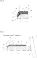
- an outer peripheral part of an outer part 11B of a substrate 11 serves as a chamfered part 11C which is chamfered to 45 degrees or chamfered in an arc shape.
- a resin film layer 12 is formed to cover most of the area of an outer part 11B including an outer peripheral edge 11B' of the outer part 11B and the chamfered part 11C.
- the conventional swash plate 2 as is shown enlarged in Fig.
- the chamfered part 11C and outer peripheral edge 11B' and the resin film layer 12 of adjacent inner sections of both are formed to be thinner than other sections along a cross-sectional shape of the chamfered part 11C and outer peripheral edge 11B'.
- a surface 2A of the swash plate 2 that is, a flat surface in the resin film layer 12, serves as a sliding surface which slides with an end surface 4B of a shoe 4.
- the outer peripheral edge of the sliding surface that is, and outer diameter of the outer peripheral edge 2A' of the flat sections of the surface of the resin film layer 12 is given as D
- the outer diameter of the outer peripheral edge 11B' of the outer part 11B of the substrate 11 is given as d, D ⁇ d in the swash plate 2. That is, in conventional products, the outer peripheral edge of a sliding surface was formerly located slightly radially inwardly, now is the outer peripheral edge 11B' of the outer part 11B.
- the swash plate 2 is mounted tilted with respect to an axis of a rotary shaft 1, rotates together with the rotary shaft 1 in this state, and the surface 2A which is a surface of the swash plate 2 (surface of the resin film layer 12) slides with the shoe 4.
- the shoe 4 which slides above the swash plate 2 slides depicting an oval shaped movement located above the surface 2A (surface of the resin film layer 12) of the swash plate 2.
- the present invention discloses a swash plate provided with a substrate formed in a disc shape and with a chamfered part on an outer peripheral edge of an outer part, and a resin film layer arranged to cover an outer part of the substrate and formed beyond an outer peripheral edge of an outer part serving as the chamfered part to cover up to the chamfered part, a flat surface of the resin film layer serving as a sliding surface sliding with a shoe, wherein the resin film layer at the chamfered part is thicker than the chamfered part and thicker than the resin film layer at a surface in an radial inner direction, the outer peripheral edge of the flat surface of the resin film layer serving as a sliding surface is located above the chamfered part serving as an outer peripheral edge of the outer part of the substrate, and a thickness of the resin film layer at the outer peripheral edge of the flat surface of the resin film layer is given as T2 and a thickness of the resin film layer at the outer peripheral edge on the outer part of the substrate is given as T1,
- the resin film layer at the chamfered part described above becomes thicker than the resin film layer on the inner side in a radial direction than the chamfered part, and the thickness T2 described above is set larger than the thickness T1.
- Fig. 1 shows the main parts of a swash plate type compressor.
- the swash plate type compressor is arranged with a disc-shaped swash plate 2 attached to be tilted to an outer peripheral part of a rotary shaft 1, a plurality of pistons 3 arranged along the rotary shaft 1 and wrap the outer peripheral part of the swash plate 2 by a notch part 3A of one end, and a plurality of hemispherical shoes 4 arranged between a pair of recess parts 3B, 3B formed within the notch 3A of each piston 3 and a front surface 2A and rear surface 2B of the swash plate 2.
- the shoe 4 is arranged with a hemispherical surface 4A which latches to the recess part 3B of the piston 3, and a flat end surface 4B which slides with the front surface 2A or rear surface 2B which are sliding surfaces of the swash plate 2.
- the shoe 4 comprises SUJ2, tempered to the hemispherical surface 4A and end surface 4B and subsequently finish processed.
- each piston 3 is adapted for reciprocated motion along the axial direction of the rotary shaft 1.
- the swash plate 2 is formed from a disc-shaped substrate 11 drilled with a through-hole 11A at the center the rotary shaft 1 passes through, and a resin film layer 12 which covers both outer parts 11B of the substrate 11. Furthermore, Fig. 2 and Fig. 3 show the outer part 11B which serves as the front surface 2A side of the swash plate 2, and the resin film layer 12 which is applied thereto and the back surface 2B is omitted.
- the substrate 11 is comprised from an iron-based material and is set to the same thickness throughout.
- the through-hole 11A of the substrate 11 serves as an inner peripheral part of the swash plate 2.
- the outer peripheral part of the outer part 11B of the substrate 11 serves as the chamfered part 11C which is chamfered at 45°.
- the resin film layer 12 is arranged in an area excluding a part of the inner peripheral part side of the outer part 11B of the substrate 11, and is arranged beyond the outer peripheral edge 11B' which serves as a boundary with the chamfered part 11C to also cover the chamfered part 11C.
- the area of the outer peripheral surface 11D (outer peripheral part of the swash plate 2) of the substrate 11 and the inner peripheral part side of the outer part 11B are in an exposed state.
- the thickness of the resin film layer 12 at the chamfered part 11C is set thicker than the thickness of the resin film layer 12 at other areas, thereby, wear of the outer peripheral edge 11B' of the outer part 11B and the resin film layer 12 in that vicinity is suppressed. More particularly, as is shown in Fig. 2 and Fig. 3 , given the outer diameter of the outer peripheral edge 2A' of the flat surface of the resin film layer 12 which serves as a sliding surface (surface 2A) which slides with the shoe 4 is given as D, and the outer diameter of the outer peripheral edge 11B' of the outer part 11B of the substrate 11 is given as d, then D> d.
- the thickness T2 of the resin film layer 12 of the chamfered part 11C which serves as the outer peripheral edge 2A' is formed to a thickness of the outer peripheral edge 11B' of the outer part 11B of about 1.5 to 2 times compared to the thickness T1 of the resin film layer 12 in an inner radial direction area.
- the thickness T2 of the resin film layer 12 in the outer peripheral edge 2A' described above is set to in the 4 ⁇ 100 ⁇ m, while the thickness of the outer peripheral edge 11B' of the outer part 11B and the thickness T1 of the resin film layer 12 in sections more to the inner side are set to 2 ⁇ 50 ⁇ m.
- the resin film layer 12 As a method for covering the outer part 11B of the substrate 11 described above using the resin film layer 12, it is possible to use the following method. That is, it is possible to employ spray coating, roll coating and stamp coating. Furthermore, more preferably, it is preferable to form the resin film layer 12 by spin coating. In the case of spin coating, first a resin coating is coated on both outer parts 11B of the substrate 11 by roll coating, following this, the substrate 11 is held in a rotation machine and rotated at an appropriate rotation speed for a desired period of time. In this way, the resin coating flows to the outer peripheral side from the inner peripheral side of the outer part 11B of the substrate 11 by centrifugal force, and it is possible to form the resin film layer 12 including the structure described above.
- spin coating first a resin coating is coated on both outer parts 11B of the substrate 11 by roll coating, following this, the substrate 11 is held in a rotation machine and rotated at an appropriate rotation speed for a desired period of time. In this way, the resin coating flows to the outer peripheral side from the inner
- the swash plate 2 of the present embodiment is structured as described above.
- the rotay shaft 1 and the swash plate 2 rotate, and the shoe 4 is located above the resin film layer 12 at the position of the outer peripheral edge 11B' of the swash plate 2 side when the piston 3 is at the top dead center or bottom dead center.
- the outer peripheral edge 2A' which is an outer peripheral edge of a sliding surface, of the flat surface of the resin film layer 12 is located in a more radially outward direction than the outer peripheral edge 11B' of the outer part 11B.
- the thickness T2 of the resin film layer 12 on the outer peripheral edge 2A' is thicker than the thickness T1 of the resin film layer 12 in the outer peripheral edge 11B' of the outer part 11B.
- the present invention is a swash plate of a swash plate type compressor and can be used as a swash plate arranged with a resin film layer serving as a sliding surface.
Landscapes
- Engineering & Computer Science (AREA)
- Mechanical Engineering (AREA)
- General Engineering & Computer Science (AREA)
- Manufacturing & Machinery (AREA)
- Compressors, Vaccum Pumps And Other Relevant Systems (AREA)
Claims (3)
- Taumelscheibe (2), die umfasst: ein Substrat (11), das in einer Scheibenform und mit einem abgefasten Teil (11C) an einem Außenumfangsrand des Außenteils gebildet ist; und eine Harzfilmschicht (12), die so angeordnet ist, dass sie das Außenteil des Substrats (11B) bedeckt, und die über einen Außenumfangsrand des Außenteils, der als das abgefaste Teil (11C) dient, hinaus gebildet ist, um bis zu dem abgefasten Teil (11C) zu bedecken, wobei eine ebene Oberfläche der Harzfilmschicht als eine Gleitfläche, die mit einem Gleitstück (4) gleitet, dient;
dadurch gekennzeichnet, dass
die Harzfilmschicht (12) bei dem abgefasten Teil (11C) dicker als die Harzfilmschicht (12) bei einer Oberfläche in einer Richtung radial nach innen ist, wobei sich der Außenumfangsrand der ebenen Oberfläche der Harzfilmschicht (2A'), die als eine Gleitfläche dient, über dem abgefasten Teil (11C) befindet, das als ein Außenumfangsrand des Außenteils des Substrats (11B) dient, und wobei eine Dicke der Harzfilmschicht (12) bei dem Außenumfangsrand der ebenen Oberfläche der Harzfilmschicht (2A') als T2 gegeben ist und wobei eine Dicke der Harzfilmschicht bei dem Außenumfangsrand auf dem Außenteil des Substrats (11B) als T1 gegeben ist, wobei die Dicke T2 größer als die Dicke T1 eingestellt ist und wobei die Oberfläche des Außenumfangsrands der ebenen Oberfläche der Harzfilmschicht (2A') gekrümmt wird. - Taumelscheibe nach Anspruch 1, wobei eine Oberfläche der Harzfilmschicht (12) bei dem abgefasten Teil (11C) und eine Oberfläche der Harzfilmschicht (12) bei dem Außenumfangsrand des Außenteils koplanar werden und wobei eine Oberfläche der Harzfilmschicht bei dem abgefasten Teil (11C) zu der Gleitfläche wird.
- Taumelscheibe nach Anspruch 1 oder Anspruch 2, wobei die Dicke T2 auf 4-100 µm eingestellt ist und die Dicke T1 auf 2-50 µm eingestellt ist.
Applications Claiming Priority (2)
| Application Number | Priority Date | Filing Date | Title |
|---|---|---|---|
| JP2012069610A JP5841471B2 (ja) | 2012-03-26 | 2012-03-26 | 斜板 |
| PCT/JP2013/058567 WO2013146677A1 (ja) | 2012-03-26 | 2013-03-25 | 斜板 |
Publications (3)
| Publication Number | Publication Date |
|---|---|
| EP2832995A1 EP2832995A1 (de) | 2015-02-04 |
| EP2832995A4 EP2832995A4 (de) | 2016-03-30 |
| EP2832995B1 true EP2832995B1 (de) | 2017-10-25 |
Family
ID=49259928
Family Applications (1)
| Application Number | Title | Priority Date | Filing Date |
|---|---|---|---|
| EP13768133.4A Active EP2832995B1 (de) | 2012-03-26 | 2013-03-25 | Taumelscheibe |
Country Status (6)
| Country | Link |
|---|---|
| US (1) | US9528504B2 (de) |
| EP (1) | EP2832995B1 (de) |
| JP (1) | JP5841471B2 (de) |
| KR (1) | KR20140126425A (de) |
| CN (1) | CN104246221A (de) |
| WO (1) | WO2013146677A1 (de) |
Families Citing this family (2)
| Publication number | Priority date | Publication date | Assignee | Title |
|---|---|---|---|---|
| JP5810020B2 (ja) * | 2012-03-29 | 2015-11-11 | 大豊工業株式会社 | 斜板 |
| JP6379381B2 (ja) * | 2014-03-18 | 2018-08-29 | 大豊工業株式会社 | 斜板式コンプレッサ |
Family Cites Families (11)
| Publication number | Priority date | Publication date | Assignee | Title |
|---|---|---|---|---|
| JP3039762B2 (ja) * | 1995-03-07 | 2000-05-08 | 株式会社豊田自動織機製作所 | 往復動型圧縮機 |
| JPH11193780A (ja) | 1997-12-26 | 1999-07-21 | Toyota Autom Loom Works Ltd | 片頭ピストン型斜板式圧縮機および斜板の製造方法 |
| JP2001349276A (ja) * | 2000-06-06 | 2001-12-21 | Zexel Valeo Climate Control Corp | 斜板式圧縮機 |
| JP2002021719A (ja) * | 2000-07-12 | 2002-01-23 | Toyota Industries Corp | 圧縮機用の斜板 |
| JP2002039062A (ja) | 2000-07-26 | 2002-02-06 | Toyota Industries Corp | 圧縮機 |
| JP4232506B2 (ja) | 2002-06-24 | 2009-03-04 | 株式会社豊田自動織機 | 摺動部品 |
| JP4025832B2 (ja) | 2003-04-14 | 2007-12-26 | 株式会社豊田自動織機 | 圧縮機 |
| JP4049082B2 (ja) * | 2003-06-19 | 2008-02-20 | 株式会社豊田自動織機 | 圧縮機 |
| JP2006266102A (ja) * | 2005-03-22 | 2006-10-05 | Ntn Corp | 斜板式コンプレッサの斜板および斜板式コンプレッサ |
| JP2009097492A (ja) * | 2007-09-27 | 2009-05-07 | Toyota Industries Corp | 斜板式圧縮機 |
| US20090097990A1 (en) * | 2007-09-27 | 2009-04-16 | Hiroshi Kubo | Swash plate type compressor |
-
2012
- 2012-03-26 JP JP2012069610A patent/JP5841471B2/ja active Active
-
2013
- 2013-03-25 EP EP13768133.4A patent/EP2832995B1/de active Active
- 2013-03-25 US US14/387,867 patent/US9528504B2/en active Active
- 2013-03-25 WO PCT/JP2013/058567 patent/WO2013146677A1/ja not_active Ceased
- 2013-03-25 CN CN201380016993.5A patent/CN104246221A/zh active Pending
- 2013-03-25 KR KR1020147028859A patent/KR20140126425A/ko not_active Ceased
Non-Patent Citations (1)
| Title |
|---|
| None * |
Also Published As
| Publication number | Publication date |
|---|---|
| JP5841471B2 (ja) | 2016-01-13 |
| US20150033940A1 (en) | 2015-02-05 |
| EP2832995A1 (de) | 2015-02-04 |
| EP2832995A4 (de) | 2016-03-30 |
| US9528504B2 (en) | 2016-12-27 |
| WO2013146677A1 (ja) | 2013-10-03 |
| JP2013199910A (ja) | 2013-10-03 |
| KR20140126425A (ko) | 2014-10-30 |
| CN104246221A (zh) | 2014-12-24 |
Similar Documents
| Publication | Publication Date | Title |
|---|---|---|
| EP0926340A3 (de) | Beschichtung einer Schrägscheibenlagerung | |
| EP2832997B1 (de) | Taumelscheibe | |
| EP2832995A1 (de) | Taumelscheibe | |
| JP2017096396A (ja) | 半割軸受 | |
| EP2796738B1 (de) | Gleitkomponente | |
| JP2014126096A (ja) | 半割スラスト軸受 | |
| JP2016191410A (ja) | トラックローラベアリング | |
| JPH09209926A (ja) | 斜板式コンプレッサ | |
| JP2011089494A (ja) | 斜板 | |
| JP2011089495A (ja) | 斜板 | |
| JP6706184B2 (ja) | コンプレッサ用斜板 | |
| EP3438452B1 (de) | Schuh und taumelscheibenverdichter mit diesem schuh | |
| JP2009257202A (ja) | シュー | |
| WO2019088163A1 (ja) | 斜板 | |
| JP2019124234A (ja) | 内燃機関のクランク軸用主軸受 | |
| JP6706185B2 (ja) | コンプレッサ用斜板 | |
| JP6937100B2 (ja) | コンプレッサ用シュー | |
| JP5339043B2 (ja) | シュー | |
| JPH11336658A (ja) | 斜板式圧縮機 | |
| JPS61149588A (ja) | 斜板式コンプレツサ | |
| JP2010071115A (ja) | シュー | |
| JP2019082147A (ja) | 斜板 | |
| JP2016180382A (ja) | 斜板式コンプレッサの半球シューおよび斜板式コンプレッサ | |
| JP2016180384A (ja) | 斜板式コンプレッサの半球シューおよび斜板式コンプレッサ | |
| JP2019082149A (ja) | 斜板 |
Legal Events
| Date | Code | Title | Description |
|---|---|---|---|
| PUAI | Public reference made under article 153(3) epc to a published international application that has entered the european phase |
Free format text: ORIGINAL CODE: 0009012 |
|
| 17P | Request for examination filed |
Effective date: 20141027 |
|
| AK | Designated contracting states |
Kind code of ref document: A1 Designated state(s): AL AT BE BG CH CY CZ DE DK EE ES FI FR GB GR HR HU IE IS IT LI LT LU LV MC MK MT NL NO PL PT RO RS SE SI SK SM TR |
|
| AX | Request for extension of the european patent |
Extension state: BA ME |
|
| DAX | Request for extension of the european patent (deleted) | ||
| RA4 | Supplementary search report drawn up and despatched (corrected) |
Effective date: 20160301 |
|
| RIC1 | Information provided on ipc code assigned before grant |
Ipc: F04B 39/02 20060101ALI20160224BHEP Ipc: F04B 27/08 20060101AFI20160224BHEP Ipc: F16C 33/20 20060101ALI20160224BHEP Ipc: F16C 33/66 20060101ALI20160224BHEP Ipc: F16C 17/04 20060101ALI20160224BHEP Ipc: F16H 23/00 20060101ALI20160224BHEP Ipc: F04B 27/10 20060101ALI20160224BHEP Ipc: F16C 33/10 20060101ALI20160224BHEP |
|
| STAA | Information on the status of an ep patent application or granted ep patent |
Free format text: STATUS: EXAMINATION IS IN PROGRESS |
|
| 17Q | First examination report despatched |
Effective date: 20161206 |
|
| GRAP | Despatch of communication of intention to grant a patent |
Free format text: ORIGINAL CODE: EPIDOSNIGR1 |
|
| STAA | Information on the status of an ep patent application or granted ep patent |
Free format text: STATUS: GRANT OF PATENT IS INTENDED |
|
| INTG | Intention to grant announced |
Effective date: 20170519 |
|
| GRAS | Grant fee paid |
Free format text: ORIGINAL CODE: EPIDOSNIGR3 |
|
| GRAA | (expected) grant |
Free format text: ORIGINAL CODE: 0009210 |
|
| STAA | Information on the status of an ep patent application or granted ep patent |
Free format text: STATUS: THE PATENT HAS BEEN GRANTED |
|
| RIN1 | Information on inventor provided before grant (corrected) |
Inventor name: GOTO, SHINGO Inventor name: YAMANE, KYOHEI Inventor name: SHIBATA, MASATO |
|
| AK | Designated contracting states |
Kind code of ref document: B1 Designated state(s): AL AT BE BG CH CY CZ DE DK EE ES FI FR GB GR HR HU IE IS IT LI LT LU LV MC MK MT NL NO PL PT RO RS SE SI SK SM TR |
|
| RAP1 | Party data changed (applicant data changed or rights of an application transferred) |
Owner name: TAIHO KOGYO CO., LTD. |
|
| REG | Reference to a national code |
Ref country code: GB Ref legal event code: FG4D |
|
| REG | Reference to a national code |
Ref country code: CH Ref legal event code: EP |
|
| REG | Reference to a national code |
Ref country code: AT Ref legal event code: REF Ref document number: 940214 Country of ref document: AT Kind code of ref document: T Effective date: 20171115 |
|
| REG | Reference to a national code |
Ref country code: IE Ref legal event code: FG4D |
|
| REG | Reference to a national code |
Ref country code: DE Ref legal event code: R096 Ref document number: 602013028447 Country of ref document: DE |
|
| REG | Reference to a national code |
Ref country code: NL Ref legal event code: MP Effective date: 20171025 |
|
| REG | Reference to a national code |
Ref country code: LT Ref legal event code: MG4D |
|
| REG | Reference to a national code |
Ref country code: AT Ref legal event code: MK05 Ref document number: 940214 Country of ref document: AT Kind code of ref document: T Effective date: 20171025 |
|
| PG25 | Lapsed in a contracting state [announced via postgrant information from national office to epo] |
Ref country code: NL Free format text: LAPSE BECAUSE OF FAILURE TO SUBMIT A TRANSLATION OF THE DESCRIPTION OR TO PAY THE FEE WITHIN THE PRESCRIBED TIME-LIMIT Effective date: 20171025 |
|
| PG25 | Lapsed in a contracting state [announced via postgrant information from national office to epo] |
Ref country code: LT Free format text: LAPSE BECAUSE OF FAILURE TO SUBMIT A TRANSLATION OF THE DESCRIPTION OR TO PAY THE FEE WITHIN THE PRESCRIBED TIME-LIMIT Effective date: 20171025 Ref country code: FI Free format text: LAPSE BECAUSE OF FAILURE TO SUBMIT A TRANSLATION OF THE DESCRIPTION OR TO PAY THE FEE WITHIN THE PRESCRIBED TIME-LIMIT Effective date: 20171025 Ref country code: SE Free format text: LAPSE BECAUSE OF FAILURE TO SUBMIT A TRANSLATION OF THE DESCRIPTION OR TO PAY THE FEE WITHIN THE PRESCRIBED TIME-LIMIT Effective date: 20171025 Ref country code: ES Free format text: LAPSE BECAUSE OF FAILURE TO SUBMIT A TRANSLATION OF THE DESCRIPTION OR TO PAY THE FEE WITHIN THE PRESCRIBED TIME-LIMIT Effective date: 20171025 Ref country code: NO Free format text: LAPSE BECAUSE OF FAILURE TO SUBMIT A TRANSLATION OF THE DESCRIPTION OR TO PAY THE FEE WITHIN THE PRESCRIBED TIME-LIMIT Effective date: 20180125 |
|
| PG25 | Lapsed in a contracting state [announced via postgrant information from national office to epo] |
Ref country code: BG Free format text: LAPSE BECAUSE OF FAILURE TO SUBMIT A TRANSLATION OF THE DESCRIPTION OR TO PAY THE FEE WITHIN THE PRESCRIBED TIME-LIMIT Effective date: 20180125 Ref country code: RS Free format text: LAPSE BECAUSE OF FAILURE TO SUBMIT A TRANSLATION OF THE DESCRIPTION OR TO PAY THE FEE WITHIN THE PRESCRIBED TIME-LIMIT Effective date: 20171025 Ref country code: HR Free format text: LAPSE BECAUSE OF FAILURE TO SUBMIT A TRANSLATION OF THE DESCRIPTION OR TO PAY THE FEE WITHIN THE PRESCRIBED TIME-LIMIT Effective date: 20171025 Ref country code: GR Free format text: LAPSE BECAUSE OF FAILURE TO SUBMIT A TRANSLATION OF THE DESCRIPTION OR TO PAY THE FEE WITHIN THE PRESCRIBED TIME-LIMIT Effective date: 20180126 Ref country code: LV Free format text: LAPSE BECAUSE OF FAILURE TO SUBMIT A TRANSLATION OF THE DESCRIPTION OR TO PAY THE FEE WITHIN THE PRESCRIBED TIME-LIMIT Effective date: 20171025 Ref country code: AT Free format text: LAPSE BECAUSE OF FAILURE TO SUBMIT A TRANSLATION OF THE DESCRIPTION OR TO PAY THE FEE WITHIN THE PRESCRIBED TIME-LIMIT Effective date: 20171025 Ref country code: IS Free format text: LAPSE BECAUSE OF FAILURE TO SUBMIT A TRANSLATION OF THE DESCRIPTION OR TO PAY THE FEE WITHIN THE PRESCRIBED TIME-LIMIT Effective date: 20180225 |
|
| REG | Reference to a national code |
Ref country code: DE Ref legal event code: R097 Ref document number: 602013028447 Country of ref document: DE |
|
| PG25 | Lapsed in a contracting state [announced via postgrant information from national office to epo] |
Ref country code: SK Free format text: LAPSE BECAUSE OF FAILURE TO SUBMIT A TRANSLATION OF THE DESCRIPTION OR TO PAY THE FEE WITHIN THE PRESCRIBED TIME-LIMIT Effective date: 20171025 Ref country code: DK Free format text: LAPSE BECAUSE OF FAILURE TO SUBMIT A TRANSLATION OF THE DESCRIPTION OR TO PAY THE FEE WITHIN THE PRESCRIBED TIME-LIMIT Effective date: 20171025 Ref country code: CY Free format text: LAPSE BECAUSE OF FAILURE TO SUBMIT A TRANSLATION OF THE DESCRIPTION OR TO PAY THE FEE WITHIN THE PRESCRIBED TIME-LIMIT Effective date: 20171025 Ref country code: EE Free format text: LAPSE BECAUSE OF FAILURE TO SUBMIT A TRANSLATION OF THE DESCRIPTION OR TO PAY THE FEE WITHIN THE PRESCRIBED TIME-LIMIT Effective date: 20171025 Ref country code: CZ Free format text: LAPSE BECAUSE OF FAILURE TO SUBMIT A TRANSLATION OF THE DESCRIPTION OR TO PAY THE FEE WITHIN THE PRESCRIBED TIME-LIMIT Effective date: 20171025 |
|
| PG25 | Lapsed in a contracting state [announced via postgrant information from national office to epo] |
Ref country code: RO Free format text: LAPSE BECAUSE OF FAILURE TO SUBMIT A TRANSLATION OF THE DESCRIPTION OR TO PAY THE FEE WITHIN THE PRESCRIBED TIME-LIMIT Effective date: 20171025 Ref country code: SM Free format text: LAPSE BECAUSE OF FAILURE TO SUBMIT A TRANSLATION OF THE DESCRIPTION OR TO PAY THE FEE WITHIN THE PRESCRIBED TIME-LIMIT Effective date: 20171025 Ref country code: PL Free format text: LAPSE BECAUSE OF FAILURE TO SUBMIT A TRANSLATION OF THE DESCRIPTION OR TO PAY THE FEE WITHIN THE PRESCRIBED TIME-LIMIT Effective date: 20171025 |
|
| PLBE | No opposition filed within time limit |
Free format text: ORIGINAL CODE: 0009261 |
|
| STAA | Information on the status of an ep patent application or granted ep patent |
Free format text: STATUS: NO OPPOSITION FILED WITHIN TIME LIMIT |
|
| 26N | No opposition filed |
Effective date: 20180726 |
|
| REG | Reference to a national code |
Ref country code: CH Ref legal event code: PL |
|
| GBPC | Gb: european patent ceased through non-payment of renewal fee |
Effective date: 20180325 |
|
| PG25 | Lapsed in a contracting state [announced via postgrant information from national office to epo] |
Ref country code: MC Free format text: LAPSE BECAUSE OF FAILURE TO SUBMIT A TRANSLATION OF THE DESCRIPTION OR TO PAY THE FEE WITHIN THE PRESCRIBED TIME-LIMIT Effective date: 20171025 Ref country code: SI Free format text: LAPSE BECAUSE OF FAILURE TO SUBMIT A TRANSLATION OF THE DESCRIPTION OR TO PAY THE FEE WITHIN THE PRESCRIBED TIME-LIMIT Effective date: 20171025 |
|
| REG | Reference to a national code |
Ref country code: BE Ref legal event code: MM Effective date: 20180331 |
|
| REG | Reference to a national code |
Ref country code: IE Ref legal event code: MM4A |
|
| PG25 | Lapsed in a contracting state [announced via postgrant information from national office to epo] |
Ref country code: LU Free format text: LAPSE BECAUSE OF NON-PAYMENT OF DUE FEES Effective date: 20180325 |
|
| PG25 | Lapsed in a contracting state [announced via postgrant information from national office to epo] |
Ref country code: IE Free format text: LAPSE BECAUSE OF NON-PAYMENT OF DUE FEES Effective date: 20180325 |
|
| PG25 | Lapsed in a contracting state [announced via postgrant information from national office to epo] |
Ref country code: LI Free format text: LAPSE BECAUSE OF NON-PAYMENT OF DUE FEES Effective date: 20180331 Ref country code: IT Free format text: LAPSE BECAUSE OF NON-PAYMENT OF DUE FEES Effective date: 20180325 Ref country code: GB Free format text: LAPSE BECAUSE OF NON-PAYMENT OF DUE FEES Effective date: 20180325 Ref country code: BE Free format text: LAPSE BECAUSE OF NON-PAYMENT OF DUE FEES Effective date: 20180331 Ref country code: CH Free format text: LAPSE BECAUSE OF NON-PAYMENT OF DUE FEES Effective date: 20180331 |
|
| PG25 | Lapsed in a contracting state [announced via postgrant information from national office to epo] |
Ref country code: FR Free format text: LAPSE BECAUSE OF NON-PAYMENT OF DUE FEES Effective date: 20180331 |
|
| PG25 | Lapsed in a contracting state [announced via postgrant information from national office to epo] |
Ref country code: MT Free format text: LAPSE BECAUSE OF NON-PAYMENT OF DUE FEES Effective date: 20180325 |
|
| PG25 | Lapsed in a contracting state [announced via postgrant information from national office to epo] |
Ref country code: TR Free format text: LAPSE BECAUSE OF FAILURE TO SUBMIT A TRANSLATION OF THE DESCRIPTION OR TO PAY THE FEE WITHIN THE PRESCRIBED TIME-LIMIT Effective date: 20171025 |
|
| PG25 | Lapsed in a contracting state [announced via postgrant information from national office to epo] |
Ref country code: PT Free format text: LAPSE BECAUSE OF FAILURE TO SUBMIT A TRANSLATION OF THE DESCRIPTION OR TO PAY THE FEE WITHIN THE PRESCRIBED TIME-LIMIT Effective date: 20171025 |
|
| PG25 | Lapsed in a contracting state [announced via postgrant information from national office to epo] |
Ref country code: MK Free format text: LAPSE BECAUSE OF NON-PAYMENT OF DUE FEES Effective date: 20171025 Ref country code: HU Free format text: LAPSE BECAUSE OF FAILURE TO SUBMIT A TRANSLATION OF THE DESCRIPTION OR TO PAY THE FEE WITHIN THE PRESCRIBED TIME-LIMIT; INVALID AB INITIO Effective date: 20130325 |
|
| PG25 | Lapsed in a contracting state [announced via postgrant information from national office to epo] |
Ref country code: AL Free format text: LAPSE BECAUSE OF FAILURE TO SUBMIT A TRANSLATION OF THE DESCRIPTION OR TO PAY THE FEE WITHIN THE PRESCRIBED TIME-LIMIT Effective date: 20171025 |
|
| PGFP | Annual fee paid to national office [announced via postgrant information from national office to epo] |
Ref country code: DE Payment date: 20260128 Year of fee payment: 14 |