EP2833012A1 - Dispositif de roulement - Google Patents
Dispositif de roulement Download PDFInfo
- Publication number
- EP2833012A1 EP2833012A1 EP20120873336 EP12873336A EP2833012A1 EP 2833012 A1 EP2833012 A1 EP 2833012A1 EP 20120873336 EP20120873336 EP 20120873336 EP 12873336 A EP12873336 A EP 12873336A EP 2833012 A1 EP2833012 A1 EP 2833012A1
- Authority
- EP
- European Patent Office
- Prior art keywords
- key groove
- inner ring
- rolling bearing
- key
- peripheral face
- Prior art date
- Legal status (The legal status is an assumption and is not a legal conclusion. Google has not performed a legal analysis and makes no representation as to the accuracy of the status listed.)
- Withdrawn
Links
- 238000005096 rolling process Methods 0.000 title claims abstract description 65
- 230000002093 peripheral effect Effects 0.000 claims abstract description 39
- 238000007789 sealing Methods 0.000 description 4
- 230000004323 axial length Effects 0.000 description 2
- 229910000831 Steel Inorganic materials 0.000 description 1
- 230000004048 modification Effects 0.000 description 1
- 238000012986 modification Methods 0.000 description 1
- 239000010959 steel Substances 0.000 description 1
Images



Classifications
-
- F—MECHANICAL ENGINEERING; LIGHTING; HEATING; WEAPONS; BLASTING
- F16—ENGINEERING ELEMENTS AND UNITS; GENERAL MEASURES FOR PRODUCING AND MAINTAINING EFFECTIVE FUNCTIONING OF MACHINES OR INSTALLATIONS; THERMAL INSULATION IN GENERAL
- F16C—SHAFTS; FLEXIBLE SHAFTS; ELEMENTS OR CRANKSHAFT MECHANISMS; ROTARY BODIES OTHER THAN GEARING ELEMENTS; BEARINGS
- F16C19/00—Bearings with rolling contact, for exclusively rotary movement
- F16C19/22—Bearings with rolling contact, for exclusively rotary movement with bearing rollers essentially of the same size in one or more circular rows, e.g. needle bearings
- F16C19/34—Bearings with rolling contact, for exclusively rotary movement with bearing rollers essentially of the same size in one or more circular rows, e.g. needle bearings for both radial and axial load
- F16C19/38—Bearings with rolling contact, for exclusively rotary movement with bearing rollers essentially of the same size in one or more circular rows, e.g. needle bearings for both radial and axial load with two or more rows of rollers
-
- F—MECHANICAL ENGINEERING; LIGHTING; HEATING; WEAPONS; BLASTING
- F16—ENGINEERING ELEMENTS AND UNITS; GENERAL MEASURES FOR PRODUCING AND MAINTAINING EFFECTIVE FUNCTIONING OF MACHINES OR INSTALLATIONS; THERMAL INSULATION IN GENERAL
- F16C—SHAFTS; FLEXIBLE SHAFTS; ELEMENTS OR CRANKSHAFT MECHANISMS; ROTARY BODIES OTHER THAN GEARING ELEMENTS; BEARINGS
- F16C25/00—Bearings for exclusively rotary movement adjustable for wear or play
- F16C25/06—Ball or roller bearings
- F16C25/08—Ball or roller bearings self-adjusting
- F16C25/083—Ball or roller bearings self-adjusting with resilient means acting axially on a race ring to preload the bearing
-
- F—MECHANICAL ENGINEERING; LIGHTING; HEATING; WEAPONS; BLASTING
- F16—ENGINEERING ELEMENTS AND UNITS; GENERAL MEASURES FOR PRODUCING AND MAINTAINING EFFECTIVE FUNCTIONING OF MACHINES OR INSTALLATIONS; THERMAL INSULATION IN GENERAL
- F16C—SHAFTS; FLEXIBLE SHAFTS; ELEMENTS OR CRANKSHAFT MECHANISMS; ROTARY BODIES OTHER THAN GEARING ELEMENTS; BEARINGS
- F16C33/00—Parts of bearings; Special methods for making bearings or parts thereof
- F16C33/30—Parts of ball or roller bearings
- F16C33/58—Raceways; Race rings
-
- F—MECHANICAL ENGINEERING; LIGHTING; HEATING; WEAPONS; BLASTING
- F16—ENGINEERING ELEMENTS AND UNITS; GENERAL MEASURES FOR PRODUCING AND MAINTAINING EFFECTIVE FUNCTIONING OF MACHINES OR INSTALLATIONS; THERMAL INSULATION IN GENERAL
- F16C—SHAFTS; FLEXIBLE SHAFTS; ELEMENTS OR CRANKSHAFT MECHANISMS; ROTARY BODIES OTHER THAN GEARING ELEMENTS; BEARINGS
- F16C33/00—Parts of bearings; Special methods for making bearings or parts thereof
- F16C33/30—Parts of ball or roller bearings
- F16C33/58—Raceways; Race rings
- F16C33/583—Details of specific parts of races
- F16C33/586—Details of specific parts of races outside the space between the races, e.g. end faces or bore of inner ring
-
- F—MECHANICAL ENGINEERING; LIGHTING; HEATING; WEAPONS; BLASTING
- F16—ENGINEERING ELEMENTS AND UNITS; GENERAL MEASURES FOR PRODUCING AND MAINTAINING EFFECTIVE FUNCTIONING OF MACHINES OR INSTALLATIONS; THERMAL INSULATION IN GENERAL
- F16C—SHAFTS; FLEXIBLE SHAFTS; ELEMENTS OR CRANKSHAFT MECHANISMS; ROTARY BODIES OTHER THAN GEARING ELEMENTS; BEARINGS
- F16C35/00—Rigid support of bearing units; Housings, e.g. caps, covers
- F16C35/04—Rigid support of bearing units; Housings, e.g. caps, covers in the case of ball or roller bearings
- F16C35/06—Mounting or dismounting of ball or roller bearings; Fixing them onto shaft or in housing
- F16C35/063—Fixing them on the shaft
-
- F—MECHANICAL ENGINEERING; LIGHTING; HEATING; WEAPONS; BLASTING
- F16—ENGINEERING ELEMENTS AND UNITS; GENERAL MEASURES FOR PRODUCING AND MAINTAINING EFFECTIVE FUNCTIONING OF MACHINES OR INSTALLATIONS; THERMAL INSULATION IN GENERAL
- F16C—SHAFTS; FLEXIBLE SHAFTS; ELEMENTS OR CRANKSHAFT MECHANISMS; ROTARY BODIES OTHER THAN GEARING ELEMENTS; BEARINGS
- F16C35/00—Rigid support of bearing units; Housings, e.g. caps, covers
- F16C35/04—Rigid support of bearing units; Housings, e.g. caps, covers in the case of ball or roller bearings
- F16C35/06—Mounting or dismounting of ball or roller bearings; Fixing them onto shaft or in housing
- F16C35/07—Fixing them on the shaft or housing with interposition of an element
- F16C35/073—Fixing them on the shaft or housing with interposition of an element between shaft and inner race ring
-
- F—MECHANICAL ENGINEERING; LIGHTING; HEATING; WEAPONS; BLASTING
- F16—ENGINEERING ELEMENTS AND UNITS; GENERAL MEASURES FOR PRODUCING AND MAINTAINING EFFECTIVE FUNCTIONING OF MACHINES OR INSTALLATIONS; THERMAL INSULATION IN GENERAL
- F16C—SHAFTS; FLEXIBLE SHAFTS; ELEMENTS OR CRANKSHAFT MECHANISMS; ROTARY BODIES OTHER THAN GEARING ELEMENTS; BEARINGS
- F16C19/00—Bearings with rolling contact, for exclusively rotary movement
- F16C19/22—Bearings with rolling contact, for exclusively rotary movement with bearing rollers essentially of the same size in one or more circular rows, e.g. needle bearings
- F16C19/34—Bearings with rolling contact, for exclusively rotary movement with bearing rollers essentially of the same size in one or more circular rows, e.g. needle bearings for both radial and axial load
- F16C19/38—Bearings with rolling contact, for exclusively rotary movement with bearing rollers essentially of the same size in one or more circular rows, e.g. needle bearings for both radial and axial load with two or more rows of rollers
- F16C19/383—Bearings with rolling contact, for exclusively rotary movement with bearing rollers essentially of the same size in one or more circular rows, e.g. needle bearings for both radial and axial load with two or more rows of rollers with tapered rollers, i.e. rollers having essentially the shape of a truncated cone
- F16C19/388—Bearings with rolling contact, for exclusively rotary movement with bearing rollers essentially of the same size in one or more circular rows, e.g. needle bearings for both radial and axial load with two or more rows of rollers with tapered rollers, i.e. rollers having essentially the shape of a truncated cone with four rows, i.e. four row tapered roller bearings
-
- F—MECHANICAL ENGINEERING; LIGHTING; HEATING; WEAPONS; BLASTING
- F16—ENGINEERING ELEMENTS AND UNITS; GENERAL MEASURES FOR PRODUCING AND MAINTAINING EFFECTIVE FUNCTIONING OF MACHINES OR INSTALLATIONS; THERMAL INSULATION IN GENERAL
- F16C—SHAFTS; FLEXIBLE SHAFTS; ELEMENTS OR CRANKSHAFT MECHANISMS; ROTARY BODIES OTHER THAN GEARING ELEMENTS; BEARINGS
- F16C2226/00—Joining parts; Fastening; Assembling or mounting parts
- F16C2226/50—Positive connections
- F16C2226/70—Positive connections with complementary interlocking parts
- F16C2226/76—Positive connections with complementary interlocking parts with tongue and groove or key and slot
Definitions
- the present invention relates to a rolling bearing apparatus, and more particularly, to a rolling bearing apparatus for use at a roll neck of a rolling mill.
- bearing apparatuses are used for the purpose of supporting a roll neck part, which is a shaft portion of a mill roll.
- the mill roll is gradually worn while steel sheets are rolled, and therefore, it is necessary to frequently replace the mill roll.
- the bearing and the roll neck part are attached to each other with a predetermined fitting clearance between them, in a so-called loose fit manner.
- a slippage occurs between an inner ring of the bearing and the roll neck part during operation of the mill roll, resulting in wear of the roll neck part having a lower hardness.
- a first key groove 62 is formed on one end face of an inner ring 61
- a second key groove 64 is formed on an outer peripheral face of a roll neck part 63.
- One end of a first key 65 is inserted into and locked to the first key groove 62, and an L-shaped other end of the first key 65 is inserted into and engaged with the second key groove 64.
- a relative slippage (called as "a creep") between the inner ring 61 and the roll neck part 63 is prevented at one side of the inner ring 61, and wear of the roll neck part 63 having a lower hardness as compared with the inner ring 61 can be prevented (see, e.g., Patent Document 1).
- a conventional creep preventing rolling bearing apparatus 71 As shown in Fig. 6 , by providing a cutout groove in a part of an inner ring 72 in an axial direction of a rolling bearing 76, there is formed a key groove 73 opened at an inner peripheral face 72i and at an outer peripheral face 72o of the inner ring 72.
- a second key groove 73' is formed on an outer peripheral face 77o of a rotation shaft 77 along an axial direction f.
- the first key groove 83 is located axially inward of the inner ring 82 with respect to the seal 89, (hereinafter referred to as "a sealed rolling bearing").
- Patent Document 1 JP 02-148704 U
- the seal 89 is provided in the axial end portion of the rolling bearing 86. Accordingly, the axial length Ls of a rolling element 84 of the sealed rolling bearing needs to be made shorter as compared with the axial length Lo of a rolling element 74 of the open type rolling bearing not provided with a seal. Therefore, there is a problem that a basic dynamic load rating is remarkably lowered.
- the "basic dynamic load rating” means a load not varying in direction and amount and which makes the rated fatigue life one million rotations, with a condition that the inner ring 72, 82 is rotated and the outer ring 75, 85 is fixed.
- the inner ring 61 is extended so that an end face of the inner ring 61 protrudes in the axial direction than a seal unit 68, and the first key groove 62 is formed by cutting a portion of the one end face of the inner ring 61. Accordingly, stress concentration may occur at an edge part of the first key groove that is cut out. Moreover, for the purpose of ensuring the basic dynamic load rating, a portion for providing the first key groove 62 had to be provided in the inner ring 61, which hinders downsizing of the entire bearing.
- the present invention has been made in view of the problems above described, and it is an object thereof to provide a creep preventing rolling bearing apparatus in which stress concentration at a key groove can be relieved while ensuring the basic dynamic load rating.
- the invention is directed to a rolling bearing apparatus comprising:
- a first embodiment is an example in which a key and a key groove have a wedge shape
- a second embodiment is an example in which a key and a key groove have a prism shape
- a third embodiment is an example in which a key has a cylindrical shape and a key groove has a shape of a semicircular groove.
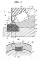
- Fig. 1(a) is a vertical sectional view illustrating a main portion of a sealed rolling bearing apparatus 11 according to the first embodiment of the present invention
- Fig. 1(b) is a cross sectional view illustrating a key structure of the sealed rolling bearing apparatus 11 of Fig. 1(a) .
- the sealed rolling bearing apparatus 11 includes a rolling bearing 16 having an inner ring 12 provided with a first key groove 13 in its axial end portion 12t, a plurality of rolling elements 14 held on an outer peripheral face 12o of the inner ring 12 in a rollable manner, and an outer ring 15 provided with a raceway face for the rolling elements 14 on its inner peripheral face 15i.
- the sealed rolling bearing apparatus 11 further includes a rotation shaft 17, and a key 18.
- the rotation shaft 17 on which the rolling bearing 16 is incorporated is provided with a second key groove 13' on its outer peripheral face 17o.
- the key 18 is inserted in a state in which the first key groove 13 and the second key groove 13' are aligned.
- the first key groove 13 is provided in the axial end portion 12t of the inner ring 12 and is opened at an inner peripheral face 12i.
- the first key groove 13 is formed so as to have a predetermined length L in the axial direction from the axial end portion 12t of the inner ring 12 at a position having a certain depth D from the outer peripheral face 12o in a radial direction.
- the first key groove 13 has a substantially quadrangular cross section. The end of the first key groove 13 is obliquely cut.
- a seal 19 for tight sealing is provided on an outer side of the rolling bearing 16 for the purpose of preventing intrusion of foreign matters.
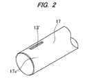
- Fig. 2 is a perspective view of the rotation shaft shown in Figs. 1(a) and 1(b) .
- the second groove 13' in a shape of an angular groove is provided on the outer peripheral face 17o of the rotation shaft 17 along the axial direction.
- a continuous key groove having a wedge shape is formed.
- the key 18 having a wedge shape is fixed at the same time.
- the first key groove 13 opened at the inner peripheral face 12i is provided in the axial end portion 12t of the inner ring 12 of the rolling bearing 16, and the second key groove 13' contiguous with the first key groove 13 is provided on the outer peripheral face 17o of the rotation shaft 17 along the axial direction.
- the key 18 having the shape of a wedge is inserted into and engaged with the key groove formed by aligning the positions of the first key groove 13 and the second key groove 13'.
- the first key groove 13 formed in the inner ring 12 and the second key groove 13' formed in the rotation shaft 17 are fixed at the same time, and thus, a creep between the inner ring 12 and the rotation shaft 17 can be prevented.
- the first key groove 13 having a shape of a substantially angular groove is formed so as to have the predetermined length L in the axial direction from the axial end portion 12t of the inner ring 12 at the position having the certain depth D from the outer peripheral face 12o of the inner ring 12 in the radial direction.
- Fig. 3(a) is a vertical sectional view illustrating a main portion of a sealed rolling bearing apparatus 21 according to the second embodiment of the present invention
- Fig. 3(b) is a cross sectional view illustrating a key structure of the sealed rolling bearing apparatus 21 of Fig. 3(a) .
- Those parts corresponding to the preceding drawings are denoted with the same reference numerals, and descriptions thereof will be omitted.
- a first key groove 23 is provided in an axial end portion 22t of an inner ring 22 and is opened at an inner peripheral face 22i.
- the first key groove 23 is formed so as to have a predetermined length L in the axial direction from the axial end portion 22t of the inner ring 22 at a position having a certain depth D from an outer peripheral face 22o in a radial direction.
- the first key groove 23 has a substantially quadrangular cross section.
- a seal 19 for tight sealing is provided on an outer side of a rolling bearing 26 for the purpose of preventing intrusion of foreign matters.
- the second groove 13' in a shape of an angular groove is provided on the outer peripheral face 17o of the rotation shaft 17 along the axial direction.
- a continuous key groove in a shape of an angular groove is formed, by aligning the first key groove 23 provided in the inner ring 22 and the second key groove 13' provided in the rotation shaft 17.
- a key 18 having a quadrangular prism shape is inserting into this key groove, the first key groove 23 and the second key groove 13' are fixed at the same time.
- the first key groove 23 opened at the inner peripheral face 22i is provided in the axial end portion 22t of the inner ring 22 of the rolling bearing 26, and the second key groove 13' contiguous with the first key groove 13 is provided on the outer peripheral face 17o of the rotation shaft 17 along the axial direction.
- the key 28 having the quadrangular prism shape is inserted into and engaged with the key groove formed by aligning positions of the first key groove 23 and the second key groove 13'.
- the first key groove 23 formed in the inner ring 22 and the second key groove 13' formed in the rotation shaft 17 are fixed at the same time, and thus, a creep between the inner ring 22 and the rotation shaft 17 can be prevented.
- the first key groove 23 having a shape of a substantially angular groove is formed so as to have the predetermined length L in the axial direction from the axial end portion 22t of the inner ring 22 at the position having the certain depth D from the outer peripheral face 22o of the inner ring 22 in the radial direction.
- a force exerted on an edge part of the first key groove 23 is dispersed, and therefore, it is possible to enhance the basic dynamic load rating, as compared with the conventional creep preventing rolling bearing apparatus in which the key groove is formed by cutting a part of an end portion of the inner ring extended in an axial direction of the bearing.
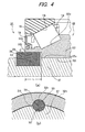
- Fig. 4(a) is a vertical sectional view illustrating a main portion of a sealed rolling bearing apparatus 31 according to a third embodiment of the present invention
- Fig. 4(b) is a cross sectional view illustrating a key structure of the sealed rolling bearing apparatus of Fig. 3(a) .
- Those parts corresponding to the preceding drawings are denoted with the same reference numerals and descriptions thereof will be omitted.
- a first key groove 33 is provided in an axial end portion 32t of an inner ring 32 and is opened at an inner peripheral face 32i.
- the first key groove 33 is formed so as to have a predetermined length L in the axial direction from the axial end portion 32t of the inner ring 32 at a position having a certain depth D from an outer peripheral face 32o in a radial direction.
- the first key groove 33 has a substantially semicircular cross section.
- a seal 19 for tight sealing is provided on an outer side of a rolling bearing 36 for the purpose of preventing intrusion of foreign matters.
- a rotation shaft 7 is provided with a second key groove 33' on its outer peripheral face 37o along an axial direction thereof.
- the second key groove 33' has a substantially semicircular shape in section.
- a continuous key groove having a circular section is formed, by aligning the first key groove 33 provided in the inner ring 32 and the second key groove 33' provided in the rotation shaft 37.
- a key 38 having a cylindrical shape is inserting into this key groove, the first key groove 33 and the second key groove 33' are fixed at the same time.
- the first key groove 33 opened at the inner peripheral face 32i is provided in the axial end portion 32t of the inner ring 32 of the rolling bearing 36, and the second key groove 33' contiguous with the first key groove 33 is provided on the outer peripheral face 37o of the rotation shaft 37 along the axial direction.
- the key 38 having the cylindrical shape is inserted into and engaged with the key groove formed by aligning positions of the first key groove 33 and the second key groove 33'.
- the first key groove 33 formed in the inner ring 32 and the second key groove 33' formed in the rotation shaft 37 are fixed at the same time, and thus, a creep between the inner ring 32 and the rotation shaft 37 can be prevented.
- the first key groove 33 is formed so as to have the predetermined length L in the axial direction from the axial end portion 32t of the inner ring 32 at the position having the certain depth D from the outer peripheral face 32o of the inner ring 22 in the radial direction.
Landscapes
- Engineering & Computer Science (AREA)
- General Engineering & Computer Science (AREA)
- Mechanical Engineering (AREA)
- Rolling Contact Bearings (AREA)
- Mounting Of Bearings Or Others (AREA)
Applications Claiming Priority (2)
| Application Number | Priority Date | Filing Date | Title |
|---|---|---|---|
| JP2012078686 | 2012-03-30 | ||
| PCT/JP2012/069048 WO2013145355A1 (fr) | 2012-03-30 | 2012-07-26 | Dispositif de roulement |
Publications (2)
| Publication Number | Publication Date |
|---|---|
| EP2833012A1 true EP2833012A1 (fr) | 2015-02-04 |
| EP2833012A4 EP2833012A4 (fr) | 2015-06-17 |
Family
ID=49258704
Family Applications (1)
| Application Number | Title | Priority Date | Filing Date |
|---|---|---|---|
| EP12873336.7A Withdrawn EP2833012A4 (fr) | 2012-03-30 | 2012-07-26 | Dispositif de roulement |
Country Status (6)
| Country | Link |
|---|---|
| US (1) | US9222506B2 (fr) |
| EP (1) | EP2833012A4 (fr) |
| JP (1) | JPWO2013145355A1 (fr) |
| CN (1) | CN203926448U (fr) |
| DE (1) | DE212012000267U1 (fr) |
| WO (1) | WO2013145355A1 (fr) |
Cited By (1)
| Publication number | Priority date | Publication date | Assignee | Title |
|---|---|---|---|---|
| WO2021156059A1 (fr) * | 2020-02-04 | 2021-08-12 | Volvo Truck Corporation | Ensemble d'extrémité de roue de véhicule et véhicule |
Families Citing this family (9)
| Publication number | Priority date | Publication date | Assignee | Title |
|---|---|---|---|---|
| US9273728B2 (en) * | 2013-09-09 | 2016-03-01 | Schaeffler Technologies AG & Co. KG | Rolling bearing having rings with stepped surfaces opposite to the raceways |
| CN105090197B (zh) * | 2015-09-02 | 2017-10-17 | 山东华芯富创电子科技有限公司 | 轴上零件定位结构 |
| CN111594543A (zh) * | 2019-09-27 | 2020-08-28 | 南京荧河谷科技有限公司 | 一种可变内径轴承的安装应用方法 |
| CN110594302A (zh) * | 2019-10-15 | 2019-12-20 | 彭绍文 | 一种轮毂轴承内圈止动机构 |
| US12291302B2 (en) * | 2020-06-16 | 2025-05-06 | Jacques Lagarrigue | Internal device having an excentric bearing for a steering column |
| JP2022067509A (ja) * | 2020-10-20 | 2022-05-06 | 株式会社デンソー | 燃料供給ポンプ |
| WO2023062145A1 (fr) * | 2021-10-15 | 2023-04-20 | thyssenkrupp rothe erde Germany GmbH | Ensemble palier principal pour éolienne |
| BE1029857B1 (de) * | 2021-10-15 | 2023-05-15 | thyssenkrupp rothe erde Germany GmbH | Hauptlageranordnung für eine Windenergieanlage |
| EP4497959A1 (fr) * | 2023-07-27 | 2025-01-29 | Flender GmbH | Agencement de palier, en particulier pour éoliennes |
Family Cites Families (14)
| Publication number | Priority date | Publication date | Assignee | Title |
|---|---|---|---|---|
| US1761490A (en) * | 1927-06-03 | 1930-06-03 | Otto H Penner | Adjustable double roller bearing |
| US1812784A (en) * | 1929-03-20 | 1931-06-30 | Jr John B Hawley | Bearing locking device |
| US3920343A (en) * | 1974-11-13 | 1975-11-18 | Us Energy | Key-and-keyway coupling for transmitting torque |
| DE2603685A1 (de) * | 1976-01-31 | 1977-08-04 | Kugelfischer G Schaefer & Co | Befestigung zweier schraeglager |
| JPH02203020A (ja) * | 1989-01-31 | 1990-08-13 | Oki Electric Ind Co Ltd | 軸受機構 |
| JPH02148704U (fr) | 1989-05-23 | 1990-12-18 | ||
| WO1993003287A1 (fr) * | 1991-08-09 | 1993-02-18 | Nobuo Takada | Roulement a billes et a rouleaux |
| JPH1034876A (ja) * | 1996-07-24 | 1998-02-10 | Toshiba Mach Co Ltd | 印刷機の回転胴軸受け部のクランプ装置 |
| US6485188B1 (en) * | 2000-04-21 | 2002-11-26 | The Timken Company | Wheel mounting with a bearing race embedded in a cast component |
| JP2009236287A (ja) * | 2008-03-28 | 2009-10-15 | Jtekt Corp | 車輪用転がり軸受装置 |
| JP2010048301A (ja) | 2008-08-20 | 2010-03-04 | Nsk Ltd | 軸受装置 |
| JP2011174571A (ja) | 2010-02-25 | 2011-09-08 | Nsk Ltd | 回転速度検出装置付き車輪支持用軸受ユニット |
| JP2012078686A (ja) | 2010-10-05 | 2012-04-19 | Japan Carlit Co Ltd:The | 液晶配向剤とそれを用いた液晶配向膜及び液晶表示素子 |
| JP2013141861A (ja) * | 2012-01-10 | 2013-07-22 | Ntn Corp | 車輪用軸受装置 |
-
2012
- 2012-07-26 CN CN201290000076.9U patent/CN203926448U/zh not_active Expired - Fee Related
- 2012-07-26 US US14/388,872 patent/US9222506B2/en active Active
- 2012-07-26 EP EP12873336.7A patent/EP2833012A4/fr not_active Withdrawn
- 2012-07-26 JP JP2014507309A patent/JPWO2013145355A1/ja active Pending
- 2012-07-26 WO PCT/JP2012/069048 patent/WO2013145355A1/fr not_active Ceased
- 2012-07-26 DE DE201221000267 patent/DE212012000267U1/de not_active Expired - Lifetime
Cited By (2)
| Publication number | Priority date | Publication date | Assignee | Title |
|---|---|---|---|---|
| WO2021156059A1 (fr) * | 2020-02-04 | 2021-08-12 | Volvo Truck Corporation | Ensemble d'extrémité de roue de véhicule et véhicule |
| US12344034B2 (en) | 2020-02-04 | 2025-07-01 | Volvo Truck Corporation | Vehicle wheel end assembly and a vehicle |
Also Published As
| Publication number | Publication date |
|---|---|
| US9222506B2 (en) | 2015-12-29 |
| JPWO2013145355A1 (ja) | 2015-12-10 |
| DE212012000267U1 (de) | 2014-11-25 |
| US20150043850A1 (en) | 2015-02-12 |
| WO2013145355A1 (fr) | 2013-10-03 |
| CN203926448U (zh) | 2014-11-05 |
| EP2833012A4 (fr) | 2015-06-17 |
Similar Documents
| Publication | Publication Date | Title |
|---|---|---|
| EP2833012A1 (fr) | Dispositif de roulement | |
| CN110785572B (zh) | 用于滚柱轴承密封件的挡油环、相关组件及方法 | |
| EP2239473B1 (fr) | Cage de roulement | |
| JP4466473B2 (ja) | 転がり軸受 | |
| US10247234B2 (en) | Bearing | |
| EP2975279A1 (fr) | Dispositif de palier à dispositif d'étanchéité | |
| EP2282072A1 (fr) | Anneau interne, anneau externe et rouleau à bille en tôle | |
| CN106050913B (zh) | 轴承及轴承装置 | |
| US20100098364A1 (en) | Roller with cage assembly | |
| US10190624B2 (en) | Spacer device, toroidal roller bearing and method | |
| EP3396184B1 (fr) | Roulement à rouleaux croisés | |
| EP1961982B1 (fr) | Roulement a rouleaux | |
| JP2017003109A (ja) | 円すいころ軸受 | |
| KR20230115985A (ko) | 베어링 장치 | |
| EP3633216A1 (fr) | Roulement à billes à double rangée et de contact sur quatre points | |
| WO2016194981A1 (fr) | Palier à rouleaux coniques | |
| JP6024291B2 (ja) | 転がり軸受 | |
| EP1373745B1 (fr) | Ensemble roulement a rouleaux | |
| JP2006300130A (ja) | 軸受構造 | |
| US9856915B2 (en) | Radial cage for bearings having high rotational speeds | |
| US9732793B2 (en) | Bearing and bearing arrangement | |
| US9328767B2 (en) | Bearing assembly | |
| US8845204B2 (en) | Spacer for rolling bearing with low friction contribution | |
| JP2011021715A (ja) | カムフォロア |
Legal Events
| Date | Code | Title | Description |
|---|---|---|---|
| PUAI | Public reference made under article 153(3) epc to a published international application that has entered the european phase |
Free format text: ORIGINAL CODE: 0009012 |
|
| 17P | Request for examination filed |
Effective date: 20140930 |
|
| AK | Designated contracting states |
Kind code of ref document: A1 Designated state(s): AL AT BE BG CH CY CZ DE DK EE ES FI FR GB GR HR HU IE IS IT LI LT LU LV MC MK MT NL NO PL PT RO RS SE SI SK SM TR |
|
| AX | Request for extension of the european patent |
Extension state: BA ME |
|
| RA4 | Supplementary search report drawn up and despatched (corrected) |
Effective date: 20150515 |
|
| RIC1 | Information provided on ipc code assigned before grant |
Ipc: F16C 33/58 20060101ALI20150508BHEP Ipc: F16C 35/073 20060101AFI20150508BHEP Ipc: F16C 19/38 20060101ALI20150508BHEP Ipc: F16C 19/36 20060101ALN20150508BHEP |
|
| DAX | Request for extension of the european patent (deleted) | ||
| RIC1 | Information provided on ipc code assigned before grant |
Ipc: F16C 35/073 20060101AFI20171115BHEP Ipc: F16C 19/36 20060101ALN20171115BHEP Ipc: F16C 19/38 20060101ALI20171115BHEP Ipc: F16C 33/58 20060101ALI20171115BHEP |
|
| 17Q | First examination report despatched |
Effective date: 20180103 |
|
| STAA | Information on the status of an ep patent application or granted ep patent |
Free format text: STATUS: THE APPLICATION IS DEEMED TO BE WITHDRAWN |
|
| 18D | Application deemed to be withdrawn |
Effective date: 20190827 |