EP2833036B1 - Valve pour pneumatique compartimenté et pneumatique compartimenté - Google Patents
Valve pour pneumatique compartimenté et pneumatique compartimenté Download PDFInfo
- Publication number
- EP2833036B1 EP2833036B1 EP13768568.1A EP13768568A EP2833036B1 EP 2833036 B1 EP2833036 B1 EP 2833036B1 EP 13768568 A EP13768568 A EP 13768568A EP 2833036 B1 EP2833036 B1 EP 2833036B1
- Authority
- EP
- European Patent Office
- Prior art keywords
- valve
- tyre
- cavity
- duct
- coupling
- Prior art date
- Legal status (The legal status is an assumption and is not a legal conclusion. Google has not performed a legal analysis and makes no representation as to the accuracy of the status listed.)
- Not-in-force
Links
- 238000004891 communication Methods 0.000 claims description 24
- 230000008878 coupling Effects 0.000 claims description 20
- 238000010168 coupling process Methods 0.000 claims description 20
- 238000005859 coupling reaction Methods 0.000 claims description 20
- 230000007246 mechanism Effects 0.000 claims description 7
- 210000002105 tongue Anatomy 0.000 claims description 5
- 238000003825 pressing Methods 0.000 claims description 2
- 238000000605 extraction Methods 0.000 description 10
- 238000005192 partition Methods 0.000 description 7
- 238000000926 separation method Methods 0.000 description 7
- 238000010586 diagram Methods 0.000 description 4
- 238000006073 displacement reaction Methods 0.000 description 4
- 238000007789 sealing Methods 0.000 description 3
- 230000008901 benefit Effects 0.000 description 2
- 238000013461 design Methods 0.000 description 2
- 230000000694 effects Effects 0.000 description 2
- 238000012423 maintenance Methods 0.000 description 2
- 238000004519 manufacturing process Methods 0.000 description 2
- 239000002184 metal Substances 0.000 description 2
- 230000001681 protective effect Effects 0.000 description 2
- 230000008859 change Effects 0.000 description 1
- 238000005516 engineering process Methods 0.000 description 1
- 230000002650 habitual effect Effects 0.000 description 1
- 238000010348 incorporation Methods 0.000 description 1
- 230000004048 modification Effects 0.000 description 1
- 238000012986 modification Methods 0.000 description 1
- 230000001012 protector Effects 0.000 description 1
- 230000002787 reinforcement Effects 0.000 description 1
Images







Classifications
-
- B—PERFORMING OPERATIONS; TRANSPORTING
- B60—VEHICLES IN GENERAL
- B60C—VEHICLE TYRES; TYRE INFLATION; TYRE CHANGING; CONNECTING VALVES TO INFLATABLE ELASTIC BODIES IN GENERAL; DEVICES OR ARRANGEMENTS RELATED TO TYRES
- B60C29/00—Arrangements of tyre-inflating valves to tyres or rims; Accessories for tyre-inflating valves, not otherwise provided for
- B60C29/007—Arrangements of tyre-inflating valves to tyres or rims; Accessories for tyre-inflating valves, not otherwise provided for for tyres with segmental sections or for multi-chamber tyres
-
- B—PERFORMING OPERATIONS; TRANSPORTING
- B60—VEHICLES IN GENERAL
- B60C—VEHICLE TYRES; TYRE INFLATION; TYRE CHANGING; CONNECTING VALVES TO INFLATABLE ELASTIC BODIES IN GENERAL; DEVICES OR ARRANGEMENTS RELATED TO TYRES
- B60C29/00—Arrangements of tyre-inflating valves to tyres or rims; Accessories for tyre-inflating valves, not otherwise provided for
- B60C29/002—Arrangements of tyre-inflating valves to tyres or rims; Accessories for tyre-inflating valves, not otherwise provided for characterised by particular features of the valve core
-
- B—PERFORMING OPERATIONS; TRANSPORTING
- B60—VEHICLES IN GENERAL
- B60C—VEHICLE TYRES; TYRE INFLATION; TYRE CHANGING; CONNECTING VALVES TO INFLATABLE ELASTIC BODIES IN GENERAL; DEVICES OR ARRANGEMENTS RELATED TO TYRES
- B60C29/00—Arrangements of tyre-inflating valves to tyres or rims; Accessories for tyre-inflating valves, not otherwise provided for
- B60C29/04—Connection to tyres or inner tubes
-
- B—PERFORMING OPERATIONS; TRANSPORTING
- B60—VEHICLES IN GENERAL
- B60C—VEHICLE TYRES; TYRE INFLATION; TYRE CHANGING; CONNECTING VALVES TO INFLATABLE ELASTIC BODIES IN GENERAL; DEVICES OR ARRANGEMENTS RELATED TO TYRES
- B60C5/00—Inflatable pneumatic tyres or inner tubes
- B60C5/02—Inflatable pneumatic tyres or inner tubes having separate inflatable inserts, e.g. with inner tubes; Means for lubricating, venting, preventing relative movement between tyre and inner tube
-
- B—PERFORMING OPERATIONS; TRANSPORTING
- B60—VEHICLES IN GENERAL
- B60C—VEHICLE TYRES; TYRE INFLATION; TYRE CHANGING; CONNECTING VALVES TO INFLATABLE ELASTIC BODIES IN GENERAL; DEVICES OR ARRANGEMENTS RELATED TO TYRES
- B60C5/00—Inflatable pneumatic tyres or inner tubes
- B60C5/12—Inflatable pneumatic tyres or inner tubes without separate inflatable inserts, e.g. tubeless tyres with transverse section open to the rim
-
- B—PERFORMING OPERATIONS; TRANSPORTING
- B60—VEHICLES IN GENERAL
- B60C—VEHICLE TYRES; TYRE INFLATION; TYRE CHANGING; CONNECTING VALVES TO INFLATABLE ELASTIC BODIES IN GENERAL; DEVICES OR ARRANGEMENTS RELATED TO TYRES
- B60C5/00—Inflatable pneumatic tyres or inner tubes
- B60C5/20—Inflatable pneumatic tyres or inner tubes having multiple separate inflatable chambers
-
- F—MECHANICAL ENGINEERING; LIGHTING; HEATING; WEAPONS; BLASTING
- F16—ENGINEERING ELEMENTS AND UNITS; GENERAL MEASURES FOR PRODUCING AND MAINTAINING EFFECTIVE FUNCTIONING OF MACHINES OR INSTALLATIONS; THERMAL INSULATION IN GENERAL
- F16K—VALVES; TAPS; COCKS; ACTUATING-FLOATS; DEVICES FOR VENTING OR AERATING
- F16K15/00—Check valves
- F16K15/20—Check valves specially designed for inflatable bodies, e.g. tyres
Definitions
- the invention is included within the sector of products, systems, devices and accessories related to tyres, wheels and inner tubes for all type of vehicles. In particular, it is integrated among the devices that allow the sealing or communication of air between the interior and the exterior of a tyre or inner tube.
- valves which allow the introduction or extraction of air at will by the use of an opening and closing mechanism.
- This type of valves have standard approved dimensions and have, in general, a flexible mechanism or a longitudinal spring which presses on a cover and which, by the use of a part external to the valve (normally located in the end of the air filling/emptying duct) produces a pressure on said flexible mechanism, leading to the opening of the valve duct.
- the typical tyres on the market have a single airtight air compartment, which means that the pressure inside the tyre or inner tube is homogeneous throughout its volume, so that the introduction or extraction of air through a single point is sufficient.
- This system has the problem that, should the breakage or puncture of the surface of the outer tread occur, an immediate loss usually occurs of the pressure inside the wheel.
- a compartmentalization system has been developed of the air in several volumes. For the introduction and extraction of air from the different volumes, maintaining it at a constant pressure, it is necessary to use a new type of valve which allows the introduction or extraction of air in several ducts simultaneously inside the wheel.
- the device object of the present patent of invention application enables the introduction or extraction of air simultaneously in several volumes, and at a homogeneous pressure, in the interior of a tyre or inner tube using the current pressurized inflation devices typical in service stations.
- known valves for simultaneous filling of multiple chambers include those described in US 2 501 937 A and CN 201 093 111 Y . However, a simplified valve design enabling separation of the chambers after filling, is needed.
- the present invention relates to a valve which allows the introduction or extraction of air in several volumes simultaneously, at the same pressure, using for this a standard tyre inflation device, without the need to perform any modification thereto and it is compatible with the habitual ducts in adapters of these devices.
- the present valve uses, as with most of the existing valves for tyres, an elastic device connected to a longitudinal part, which is in turn solidly joined to the valve cover.
- an elastic device connected to a longitudinal part, which is in turn solidly joined to the valve cover.
- the inner protuberance of the inflation device adapter enters in contact with the protector of the longitudinal part forcing its displacement.
- the valve cover opens, allowing the inlet or outlet of air therethrough.
- the elastic device pushes the cover to its original position, causing, again, the sealing of the valve.
- the special characteristic of the valve object of the present invention consists of the inner part of the valve being divided into several ducts. Each one of these ducts communicates with each one of the airtight volumes of pressurized air wherein the interior of the tyre or inner tube has been divided.
- the preferred embodiment includes all these ducts in the interior of an elastic duct of standard diameter, similar to those typically used to communicate the valve with the interior of the wheel. Many other embodiments can be chosen, depending whether it is decided, or not, to modify the orifice existing in the metal rim to allow the incorporation of communication ducts of another type.
- Compartmentalized tyre is understood in the invention to be that tyre, both with or without inner tube, comprising a plurality of airtight volumes inside. These compartments can be several volumes within the tyre without inner tube or several chambers within a tyre tread. In the closed position of the valve, the airtight volumes are isolated from one another.
- the valve has a body (1) which has a first end (1A) configured for coupling to inflation/deflation means (50) of the compartmentalized tyre; a second end (1B), opposite the first end, configured for coupling to an inflation/deflation duct (3) of the compartmentalized tyre; a flow channel (1C) between the first end (1A) and the second end (1 B).
- the valve comprises:
- the cavities (14, 15) in the interior of the valve body (1) make it possible to connect several ducts (65, 93, 96) from several volumes (61, 62, 94, 95) in the tyre through a single orifice in the rim, that incorporated in conventional rims, without the need to make an orifice in the rim to connect each tyre duct (65, 93, 96) with each valve cavity (14,15).
- the invention is valid both for tyres without inner tube, for example those common in motor vehicles, and for tyres with inner tube, for example those common in bicycles.
- the valve of the invention allows combining compartmentalized tyres with conventional rings, used with tyres which have a single volume or compartment. In other words, it is not necessary to manufacture a specific rim for the case that the tyre that is going to be mounted is compartmentalized.
- the fact that the valve allows that a universal rim can be used for all types of tyres brings substantial benefits, not only financial due to the saving in the manufacturing of a considerably more complex rim -several orifices instead of one- but also in the assembly and later maintenance works of the wheel.
- the simple pressure control operation of the tyre with the valve of the invention does not require any special actuation, it also being compatible with the inflation/deflation apparatus of service stations.
- the invention has the advantages of having a compartmentalized tyre in a conventional rim, which can be inflated/deflated with the apparatus commonly found in service stations.
- the combination of the valve and tyre of the invention avoids all the unresolved complications in the state of the art.
- using multiple cavities that form subdivisions inside a single cylinder makes it possible to maximize the air flow in relation to the diameter of the tube that passes through this cylinder, since the only restriction to the general airflow is given by the size of the partition walls that may be of small size.
- FIG. 1A1-2B3 A preferred embodiment of the invention is described below. This uses a valve which is compatible both with the current rim designs and the existing systems for the introduction or extraction of pressurized air in the wheels. As shown in figures 1A1-2B3 , the body has been separated from the actual valve (1) of the adapter (2) which connects it with the elastic air inlet and outlet duct of the wheel (3).
- a wheel has been chosen which has two independent volumes of air.
- the air enters and exits the wheel through an elastic duct divided longitudinally in two independent volumes, as shown in figures 8A-8B .
- the valve described in this section is divided, in its inner part, in two separate compartments which are communicated with each one of the two duct volumes.
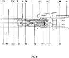
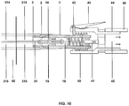
- figures 9 , 10 and 11 the operating diagram of the complete system in different inflation or deflation situations of the tyre can be observed.
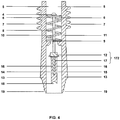
- FIG. 3 shows the components of this valve in detail.
- a longitudinal part (10) is fastened to the end of an elastic mechanism (8) by a set screw (9).
- This longitudinal part is solidly joined to a cover (12) and a panel (17) which is displaced in contact with the inner surface of the guide (13), dividing it into two symmetrical volumes (14 and 15).
- the panel is displaced through a cavity existing in the central wall of the lower part of the valve (16) and two small side grooves.
- the elastic mechanism (8) is fastened to the inlet duct of the valve (11), by the other end, by two fasteners (6).
- the valve has a thread (7) for coupling to a protective cap. This thread is similar to those currently used by this type of valves.
- Figure 4 shows how, on making a pressure on the contact head (4) of the longitudinal part (10), this moves towards the interior of the valve, moving the cover (12) and allowing the exterior (5) and interior (14 and 15) volumes to come into communication with one another.
- valve cover The effect of the opening of the valve cover can be explicitly observed in figures 5A-6B .
- a sectional drawing has been made to the same height in open and closed conditions.
- figures 5A-5B (closed valve) show how the inner volumes (14 and 15) are confined to the spaces defined by the lower wall of the valve (13) and by the panel (17), forming two compartments without communication.
- Figures 6A-6B show how the inner volumes (14 and 15) are in communication, since the longitudinal part (10) does not cover all the space inside the lower wall (13).
- the fixing of the valve (1) to the elastic duct (3) has a privileged position which is marked by the plane which contains the inner partition wall of volumes of the tube (31) and by the plane of displacement of the panel in the valve (17), which must coincide. For this reason, and due to the need to have a simple access to longitudinally fasten the inner wall of the elastic duct to the device, the use of an adapter (2) has been chosen.
- Figures 7A-7C show the adapter, comprising a first toothed surface (23) for its fixing to the valve and a second toothed surface (24) for its fixing to the elastic duct. Likewise, it has a longitudinal notch (22) where the partition wall of the elastic duct and a longitudinal protuberance (21) is fixed, parallel to the previous, which enables its correct fixing to the valve.
- FIG 9 shows the diagram of the complete system in the situation wherein the pressurized air is introduced in the wheel (inflated) by the use of an external inflation and deflation system (40).
- the air introduced by the pressurized air inflation system crosses the elastic duct of said system (50), until reaching the inside of the adapter (40).
- the cover of the valve is open due to the effect of the pressure of the protuberance (41) on the longitudinal part (10).
- the air pumped through the system as it is at a higher pressure than the air inside the wheel, circulates through each one of the two volumes (14 and 15), towards the inside thereof, traversing the valve (1), the adapter (2) and the elastic duct of the tyre (3).
- the current rims (60) have, a cylindrical orifice in their external part with pre-established dimensions to be able to introduce the elastic duct which communicates the tyre with the closure valve.
- Figure 10 shows a similar diagram to that of figure 9 , proceeding, in this case, to reduce the inner pressure of the tyre by extraction of the air to the outside (deflation).
- the air that is in the inflation or deflation system duct is initially at a lower pressure.
- Figure 11 shows a diagram similar to that of figures 9 and 10 , in the situation wherein the inflation or deflation system only fulfils the function of opening the valve cover allowing the free circulation of air between the two volumes (14 and 15) until the pressure is equalled between both.
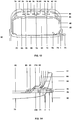
- a tyre is used formed by a reinforced outer tread, similar to that of the tyres existing at present, which has an airtight separation between the main volume and secondary volumes, fixing this wall by a series of semi-rigid surfaces perpendicular to the outer tread and parallel to one another, and which have orifices which interconnect the secondary volumes.
- a two-duct inlet valve has been used.
- air is introduced at the same pressure through two independent ducts, one of which directly connects to the main volume and the other to two tubes which reach the ends of the secondary volumes.
- the secondary volumes are intercommunicated, being completely isolated from the main volume so that, in the event an air leak occurs in the main volume or in any of the secondary volumes, this pressure decrease would solely affect one of the two systems.
- the inclusion of the semi-rigid elements contributes to the tyre undergoing a lesser degree of deformation in relation to its vertical symmetry when driving on curves, providing greater stability and adherence to the vehicle than a traditional tyre.
- figure 15 shows an application of the valve object of the invention to an inner tube of pressurized air or gas of a tyre with inner tube similar to those used in bicycles, mopeds and motorcycles.
- the inner tube has two airtight volumes or compartments (main or upper and secondary or lower) which connect with the valve through a tube divided longitudinally in two independent ducts. This also allows the simultaneous inflation and deflation at the same pressure and the maintenance of an effective diameter in the case of breakage of the tread of the inner tube in contact with the lower volume that avoids loss of control of the vehicle.
Landscapes
- Engineering & Computer Science (AREA)
- Mechanical Engineering (AREA)
- General Engineering & Computer Science (AREA)
- Check Valves (AREA)
- Tires In General (AREA)
Claims (13)
- Valve pour un pneu compartimenté, ladite valve présentant un corps (1) avec une première extrémité (1A) prévue pour être raccordée à un moyen de gonflage/dégonflage (50) du pneu compartimenté ; une deuxième extrémité (1B) opposée à la première extrémité, prévue pour être raccordée à un conduit de gonflage/dégonflage (3) du pneu-compartimenté ; un canal de circulation (1C) entre la première extrémité (1A) et la deuxième extrémité (1B), comprenant :a) au moins deux cavités présentées à l'intérieur du corps (1) de valve :a1) une première cavité (14) comprenant un premier moyen de connexion (141) à un premier compartiment (61, 94) du pneu;a2) une deuxième cavité (15) comprenant un deuxième moyen de connexion (151) à un deuxième compartiment (62, 95) du pneu;b) un canal de communication (1D) entre la première cavité (14) et la deuxième cavité (15) ;caractérisée en ce qu'elle comprend en outre :c) un élément d'ouverture/de fermeture (172) formé par :c1) un obturateur d'ouverture/de fermeture (12) du canal de circulation (1C) ;c2) un séparateur de connexion/de déconnexion (17) du canal de communication (1D).
- Valve selon la revendication 1, où l'élément d'ouverture/de fermeture (172) est mobile entre :une position d'ouverture où la première cavité (14) et la deuxième cavité (15) communiquent simultanément avec la même pression ;une position de fermeture où la première cavité (14) et la deuxième cavité (15) sont isolées l'une de l'autre.
- Valve selon la revendication 1, où l'obturateur d'ouverture/de fermeture (12) et le séparateur de connexion/de déconnexion (17) sont déplacés simultanément entre la position d'ouverture et la position de fermeture par mouvement axial longitudinal.
- Valve selon la revendication 1, comprenant des moyens de guidage (16) définissant une course d'ouverture/de fermeture du séparateur de connexion/de déconnexion (17) entre la position d'ouverture et la position de fermeture.
- Valve selon la revendication 4, où le séparateur de connexion/de déconnexion (17) présente un premier cran (17A) et une première saillie (17B) situés dans une zone de contact entre le séparateur de connexion/de déconnexion (17) et une paroi de la première cavité (14) et de la deuxième cavité (15).
- Valve selon la revendication 1, où une paroi intérieure de la valve (13) présente un deuxième cran (13A) et une deuxième saillie (13B) situés dans une zone de fermeture entre la paroi intérieure de la valve (13) et les moyens de guidage (16).
- Valve selon la revendication 1, comprenant un adaptateur (2) avec :a) une première embouchure (2A) à raccorder à la deuxième extrémité (1B) en formant un joint première embouchure (2A) - deuxième extrémité (1B) ;b) une deuxième embouchure (2B) opposée à la première embouchure à raccorder à un conduit de gonflage/dégonflage (3) du pneumatique ;c) un premier conduit (214) à raccorder à la première cavité (14) ;d) un deuxième conduit (215) à raccorder à la deuxième cavité (15) ;e) des moyens de positionnement (21) déterminant une position de raccordement entre le corps (1) et l'adaptateur (2), la connexion premier conduit (214) - première cavité (14) et la connexion deuxième conduit (215) - deuxième cavité (15) permettant un écoulement de gaz sans pertes dans le joint première embouchure (2A) - deuxième extrémité (1B).
- Valve selon la revendication 7, où l'adaptateur (2) présente une pluralité de languettes (22a, 22b) sur les côtés dé parois intérieures de l'adaptateur (2), lesdites languettes (22a, 22b) définissant des moyens de connexion avec une paroi intérieure (31) du conduit de gonflage/dégonflage (3) en fonction d'une position de connexion définie.
- Valve selon la revendication 1, comprenant un mécanisme élastique (8, 9) prévu pour permettre l'ouverture de la valve par application d'une pression sur une tête de contact (4).
- Pneu compartimenté, comprenant une valve selon l'une des revendications précédentes.
- Pneu compartimenté selon la revendication 10, comprenant une pluralité de conduits d'admission et d'évacuation de gaz (80, 83, 93, 96) :reliant le premier compartiment (61, 94) et le deuxième compartiment (62, 95) à l'extérieur via la valve ;disposés parallèlement entre eux dans une zone extérieure à un bord (60).
- Pneu compartimenté selon la revendication 11, comprenant un conduit de gonflage/dégonflage (3) comprenant les conduits d'admission et d'évacuation de gaz (80, 83, 93, 96) dans une zone extérieure au bord (60).
- Pneu compartimenté selon la revendication 10, où celui-ci est sélectionné entre un pneumatique sans un tuyau et un pneumatique avec un tuyau.
Applications Claiming Priority (3)
| Application Number | Priority Date | Filing Date | Title |
|---|---|---|---|
| ES201200335A ES2427547B1 (es) | 2012-03-28 | 2012-03-28 | Válvula de paso de aire con tránsito a través de más de un conducto |
| ES201200336A ES2427490B1 (es) | 2012-03-28 | 2012-03-28 | Neumático con distribución de gases a presión en varios volúmenes estancos y válvula única |
| PCT/ES2013/000083 WO2013144395A2 (fr) | 2012-03-28 | 2013-03-27 | Valve pour pneumatique compartimenté et pneumatique compartimenté |
Publications (3)
| Publication Number | Publication Date |
|---|---|
| EP2833036A2 EP2833036A2 (fr) | 2015-02-04 |
| EP2833036A4 EP2833036A4 (fr) | 2015-12-16 |
| EP2833036B1 true EP2833036B1 (fr) | 2017-05-03 |
Family
ID=49261340
Family Applications (1)
| Application Number | Title | Priority Date | Filing Date |
|---|---|---|---|
| EP13768568.1A Not-in-force EP2833036B1 (fr) | 2012-03-28 | 2013-03-27 | Valve pour pneumatique compartimenté et pneumatique compartimenté |
Country Status (11)
| Country | Link |
|---|---|
| US (1) | US20160257175A1 (fr) |
| EP (1) | EP2833036B1 (fr) |
| JP (1) | JP2015512826A (fr) |
| KR (1) | KR20140138636A (fr) |
| CN (1) | CN104204636B (fr) |
| AU (1) | AU2013241638B2 (fr) |
| BR (1) | BR112014018639A8 (fr) |
| CA (1) | CA2868642A1 (fr) |
| MX (1) | MX2014011662A (fr) |
| RU (1) | RU2596690C2 (fr) |
| WO (1) | WO2013144395A2 (fr) |
Families Citing this family (4)
| Publication number | Priority date | Publication date | Assignee | Title |
|---|---|---|---|---|
| TWI585296B (zh) * | 2015-08-12 | 2017-06-01 | 雙餘實業有限公司 | Double gas nozzle inflatable joints |
| US11085549B1 (en) | 2019-03-26 | 2021-08-10 | Pacific Industrial Co., Ltd. | Valve |
| CN111688411A (zh) * | 2020-06-26 | 2020-09-22 | 李开健 | 一种汽车内胎及轮胎 |
| TWI851253B (zh) * | 2023-06-01 | 2024-08-01 | 吳樹木 | 高壓氣瓶充氣裝置 |
Family Cites Families (17)
| Publication number | Priority date | Publication date | Assignee | Title |
|---|---|---|---|---|
| GB191102326A (en) * | 1911-01-30 | 1911-05-25 | Augustin Scherber | An Improved Valve for Pneumatic Tyres. |
| US2059045A (en) * | 1935-06-10 | 1936-10-27 | Edward A Seymour | Valve structure |
| US2501937A (en) * | 1945-10-08 | 1950-03-28 | Clarence U Gramelspacher | Inflation device for safety tubes |
| GB1503489A (en) * | 1974-03-28 | 1978-03-08 | Molehurst Ltd | Tyre interiors |
| JPS50152302U (fr) * | 1974-06-04 | 1975-12-18 | ||
| JPS5110502A (fr) * | 1974-07-15 | 1976-01-28 | Nissan Motor | |
| US3967670A (en) * | 1974-08-20 | 1976-07-06 | Molehurst Limited | Tires |
| SU638498A1 (ru) * | 1976-03-18 | 1978-12-25 | Solovev Valerij A | Автоматический вентиль соловьева в.а. дл многосекционной камеры пневматической шины |
| JPS5440407A (en) * | 1977-09-02 | 1979-03-29 | Patentesu Intern De Behikurosu | Inner tube |
| DE3105941A1 (de) * | 1981-02-18 | 1982-09-02 | Ernst Dipl.-Kfm. Dr. 7100 Heilbronn Haag | Mehrkammerfolie mit mehrkammerventil |
| FR2605269B1 (fr) * | 1986-10-15 | 1990-01-05 | Barek Abdoula | Pneumatique de securite a plusieurs compartiments |
| FR2761748A1 (fr) * | 1997-04-02 | 1998-10-09 | Michelin & Cie | Valve pour ensemble pneumatique et jante equipe d'une membrane de soutien pneumatique |
| CN201093111Y (zh) * | 2007-08-15 | 2008-07-30 | 梁伟 | 机动车轮胎防爆限压阀 |
| AR070747A1 (es) * | 2008-07-11 | 2010-05-05 | Col Ven Sa | Mejora en dispositivo valvular de tres vias controlable a presion |
| CN201407398Y (zh) * | 2009-04-22 | 2010-02-17 | 周建业 | 一种多气室压差阻断充气阀及其配合组成的气门咀 |
| CN201405689Y (zh) * | 2009-05-15 | 2010-02-17 | 周建业 | 一种多气室压差阻断充气阀 |
| DE202010000254U1 (de) * | 2010-02-24 | 2010-04-22 | Ptg Reifendruckregelsysteme Gmbh | Reifenventil |
-
2013
- 2013-03-27 JP JP2015502388A patent/JP2015512826A/ja active Pending
- 2013-03-27 BR BR112014018639A patent/BR112014018639A8/pt not_active IP Right Cessation
- 2013-03-27 EP EP13768568.1A patent/EP2833036B1/fr not_active Not-in-force
- 2013-03-27 KR KR1020147022932A patent/KR20140138636A/ko not_active Withdrawn
- 2013-03-27 MX MX2014011662A patent/MX2014011662A/es unknown
- 2013-03-27 RU RU2014143214/06A patent/RU2596690C2/ru not_active IP Right Cessation
- 2013-03-27 WO PCT/ES2013/000083 patent/WO2013144395A2/fr not_active Ceased
- 2013-03-27 US US14/351,104 patent/US20160257175A1/en not_active Abandoned
- 2013-03-27 CA CA2868642A patent/CA2868642A1/fr not_active Abandoned
- 2013-03-27 AU AU2013241638A patent/AU2013241638B2/en not_active Ceased
- 2013-03-27 CN CN201380016472.XA patent/CN104204636B/zh not_active Expired - Fee Related
Also Published As
| Publication number | Publication date |
|---|---|
| EP2833036A4 (fr) | 2015-12-16 |
| KR20140138636A (ko) | 2014-12-04 |
| EP2833036A2 (fr) | 2015-02-04 |
| US20160257175A1 (en) | 2016-09-08 |
| WO2013144395A2 (fr) | 2013-10-03 |
| RU2014143214A (ru) | 2016-05-20 |
| CN104204636A (zh) | 2014-12-10 |
| MX2014011662A (es) | 2015-02-13 |
| RU2596690C2 (ru) | 2016-09-10 |
| JP2015512826A (ja) | 2015-04-30 |
| CN104204636B (zh) | 2016-05-18 |
| AU2013241638A1 (en) | 2014-08-07 |
| BR112014018639A2 (fr) | 2017-06-20 |
| AU2013241638B2 (en) | 2016-09-01 |
| CA2868642A1 (fr) | 2013-10-03 |
| WO2013144395A3 (fr) | 2013-11-21 |
| BR112014018639A8 (pt) | 2017-07-11 |
Similar Documents
| Publication | Publication Date | Title |
|---|---|---|
| AU2013241638B2 (en) | Valve for a compartmentalized tyre and compartmentalized tyre | |
| CN103863030B (zh) | 空气维持充气轮胎 | |
| CN102452283B (zh) | 自充气轮胎组件 | |
| US5479976A (en) | Three-chamber tire | |
| CN102452278B (zh) | 轮胎和自充气装置组件 | |
| CN102089558B (zh) | 压力控制式三通阀设备 | |
| US9308784B2 (en) | Pneumatic tire comprising an air pressure regulator and pressure regulator kit | |
| CN104709005B (zh) | 带有压力调节器的双向自充气轮胎 | |
| ITTO20100264A1 (it) | Kit per la riparazione e il gonfiaggio di articoli gonfiabili | |
| CN104709017A (zh) | 带有压力调节器的自充气轮胎 | |
| EP3243674B1 (fr) | Valve à multiples conduits de passage et à étanchéité augmentée | |
| CN105793597A (zh) | 排空销与孔之间的空气的滑动卡钳盘式制动器 | |
| JP2015117017A (ja) | 蠕動空気ポンプチューブとタイヤとの組立体および方法 | |
| CN104417295A (zh) | 用于自充气轮胎的紧凑型阀系统 | |
| CN102452178B (zh) | 制造自充气轮胎的方法 | |
| ES2213239T3 (es) | Rueda de neumatico y sus componentes. | |
| JP2015117014A (ja) | 空気維持タイヤ用のスナップ式の入口および接続方法 | |
| KR101140526B1 (ko) | 에어 밸브가 구비된 자동차용 휠 | |
| EP3450224B1 (fr) | Soupape de commande pour un pneu de maintenance d'air | |
| CN208646834U (zh) | 一种用于汽车制动的气压控制阀 | |
| US20220097467A1 (en) | Valve assembly for tires | |
| KR100320258B1 (ko) | 자동차 타이어용 공기압 게이지 | |
| IT201900014574A1 (it) | Gruppo di sicurezza per pneumatici | |
| ES2427547B1 (es) | Válvula de paso de aire con tránsito a través de más de un conducto | |
| CN103241067A (zh) | 捆绑式防爆汽车内胎 |
Legal Events
| Date | Code | Title | Description |
|---|---|---|---|
| PUAI | Public reference made under article 153(3) epc to a published international application that has entered the european phase |
Free format text: ORIGINAL CODE: 0009012 |
|
| 17P | Request for examination filed |
Effective date: 20141016 |
|
| AK | Designated contracting states |
Kind code of ref document: A2 Designated state(s): AL AT BE BG CH CY CZ DE DK EE ES FI FR GB GR HR HU IE IS IT LI LT LU LV MC MK MT NL NO PL PT RO RS SE SI SK SM TR |
|
| AX | Request for extension of the european patent |
Extension state: BA ME |
|
| DAX | Request for extension of the european patent (deleted) | ||
| REG | Reference to a national code |
Ref country code: DE Ref legal event code: R079 Ref document number: 602013020687 Country of ref document: DE Free format text: PREVIOUS MAIN CLASS: F16K0011000000 Ipc: F16K0015200000 |
|
| A4 | Supplementary search report drawn up and despatched |
Effective date: 20151117 |
|
| RIC1 | Information provided on ipc code assigned before grant |
Ipc: F16K 15/20 20060101AFI20151111BHEP Ipc: B60C 5/20 20060101ALI20151111BHEP Ipc: B60C 29/00 20060101ALI20151111BHEP |
|
| GRAP | Despatch of communication of intention to grant a patent |
Free format text: ORIGINAL CODE: EPIDOSNIGR1 |
|
| INTG | Intention to grant announced |
Effective date: 20161025 |
|
| STAA | Information on the status of an ep patent application or granted ep patent |
Free format text: STATUS: GRANT OF PATENT IS INTENDED |
|
| GRAS | Grant fee paid |
Free format text: ORIGINAL CODE: EPIDOSNIGR3 |
|
| GRAA | (expected) grant |
Free format text: ORIGINAL CODE: 0009210 |
|
| STAA | Information on the status of an ep patent application or granted ep patent |
Free format text: STATUS: THE PATENT HAS BEEN GRANTED |
|
| AK | Designated contracting states |
Kind code of ref document: B1 Designated state(s): AL AT BE BG CH CY CZ DE DK EE ES FI FR GB GR HR HU IE IS IT LI LT LU LV MC MK MT NL NO PL PT RO RS SE SI SK SM TR |
|
| REG | Reference to a national code |
Ref country code: GB Ref legal event code: FG4D |
|
| REG | Reference to a national code |
Ref country code: AT Ref legal event code: REF Ref document number: 890370 Country of ref document: AT Kind code of ref document: T Effective date: 20170515 Ref country code: CH Ref legal event code: EP |
|
| REG | Reference to a national code |
Ref country code: IE Ref legal event code: FG4D |
|
| REG | Reference to a national code |
Ref country code: DE Ref legal event code: R096 Ref document number: 602013020687 Country of ref document: DE |
|
| REG | Reference to a national code |
Ref country code: CH Ref legal event code: NV Representative=s name: STOLMAR AND PARTNER INTELLECTUAL PROPERTY S.A., CH |
|
| REG | Reference to a national code |
Ref country code: NL Ref legal event code: MP Effective date: 20170503 |
|
| REG | Reference to a national code |
Ref country code: AT Ref legal event code: MK05 Ref document number: 890370 Country of ref document: AT Kind code of ref document: T Effective date: 20170503 |
|
| REG | Reference to a national code |
Ref country code: LT Ref legal event code: MG4D |
|
| REG | Reference to a national code |
Ref country code: CH Ref legal event code: PCAR Free format text: NEW ADDRESS: RUE DU CENDRIER 15 CP 1489, 1201 GENEVE (CH) |
|
| PG25 | Lapsed in a contracting state [announced via postgrant information from national office to epo] |
Ref country code: NO Free format text: LAPSE BECAUSE OF FAILURE TO SUBMIT A TRANSLATION OF THE DESCRIPTION OR TO PAY THE FEE WITHIN THE PRESCRIBED TIME-LIMIT Effective date: 20170803 Ref country code: FI Free format text: LAPSE BECAUSE OF FAILURE TO SUBMIT A TRANSLATION OF THE DESCRIPTION OR TO PAY THE FEE WITHIN THE PRESCRIBED TIME-LIMIT Effective date: 20170503 Ref country code: HR Free format text: LAPSE BECAUSE OF FAILURE TO SUBMIT A TRANSLATION OF THE DESCRIPTION OR TO PAY THE FEE WITHIN THE PRESCRIBED TIME-LIMIT Effective date: 20170503 Ref country code: AT Free format text: LAPSE BECAUSE OF FAILURE TO SUBMIT A TRANSLATION OF THE DESCRIPTION OR TO PAY THE FEE WITHIN THE PRESCRIBED TIME-LIMIT Effective date: 20170503 Ref country code: ES Free format text: LAPSE BECAUSE OF FAILURE TO SUBMIT A TRANSLATION OF THE DESCRIPTION OR TO PAY THE FEE WITHIN THE PRESCRIBED TIME-LIMIT Effective date: 20170503 Ref country code: LT Free format text: LAPSE BECAUSE OF FAILURE TO SUBMIT A TRANSLATION OF THE DESCRIPTION OR TO PAY THE FEE WITHIN THE PRESCRIBED TIME-LIMIT Effective date: 20170503 Ref country code: GR Free format text: LAPSE BECAUSE OF FAILURE TO SUBMIT A TRANSLATION OF THE DESCRIPTION OR TO PAY THE FEE WITHIN THE PRESCRIBED TIME-LIMIT Effective date: 20170804 |
|
| PG25 | Lapsed in a contracting state [announced via postgrant information from national office to epo] |
Ref country code: SE Free format text: LAPSE BECAUSE OF FAILURE TO SUBMIT A TRANSLATION OF THE DESCRIPTION OR TO PAY THE FEE WITHIN THE PRESCRIBED TIME-LIMIT Effective date: 20170503 Ref country code: IS Free format text: LAPSE BECAUSE OF FAILURE TO SUBMIT A TRANSLATION OF THE DESCRIPTION OR TO PAY THE FEE WITHIN THE PRESCRIBED TIME-LIMIT Effective date: 20170903 Ref country code: PL Free format text: LAPSE BECAUSE OF FAILURE TO SUBMIT A TRANSLATION OF THE DESCRIPTION OR TO PAY THE FEE WITHIN THE PRESCRIBED TIME-LIMIT Effective date: 20170503 Ref country code: NL Free format text: LAPSE BECAUSE OF FAILURE TO SUBMIT A TRANSLATION OF THE DESCRIPTION OR TO PAY THE FEE WITHIN THE PRESCRIBED TIME-LIMIT Effective date: 20170503 Ref country code: RS Free format text: LAPSE BECAUSE OF FAILURE TO SUBMIT A TRANSLATION OF THE DESCRIPTION OR TO PAY THE FEE WITHIN THE PRESCRIBED TIME-LIMIT Effective date: 20170503 Ref country code: BG Free format text: LAPSE BECAUSE OF FAILURE TO SUBMIT A TRANSLATION OF THE DESCRIPTION OR TO PAY THE FEE WITHIN THE PRESCRIBED TIME-LIMIT Effective date: 20170803 Ref country code: LV Free format text: LAPSE BECAUSE OF FAILURE TO SUBMIT A TRANSLATION OF THE DESCRIPTION OR TO PAY THE FEE WITHIN THE PRESCRIBED TIME-LIMIT Effective date: 20170503 |
|
| PG25 | Lapsed in a contracting state [announced via postgrant information from national office to epo] |
Ref country code: DK Free format text: LAPSE BECAUSE OF FAILURE TO SUBMIT A TRANSLATION OF THE DESCRIPTION OR TO PAY THE FEE WITHIN THE PRESCRIBED TIME-LIMIT Effective date: 20170503 Ref country code: RO Free format text: LAPSE BECAUSE OF FAILURE TO SUBMIT A TRANSLATION OF THE DESCRIPTION OR TO PAY THE FEE WITHIN THE PRESCRIBED TIME-LIMIT Effective date: 20170503 Ref country code: SK Free format text: LAPSE BECAUSE OF FAILURE TO SUBMIT A TRANSLATION OF THE DESCRIPTION OR TO PAY THE FEE WITHIN THE PRESCRIBED TIME-LIMIT Effective date: 20170503 Ref country code: EE Free format text: LAPSE BECAUSE OF FAILURE TO SUBMIT A TRANSLATION OF THE DESCRIPTION OR TO PAY THE FEE WITHIN THE PRESCRIBED TIME-LIMIT Effective date: 20170503 Ref country code: CZ Free format text: LAPSE BECAUSE OF FAILURE TO SUBMIT A TRANSLATION OF THE DESCRIPTION OR TO PAY THE FEE WITHIN THE PRESCRIBED TIME-LIMIT Effective date: 20170503 |
|
| REG | Reference to a national code |
Ref country code: DE Ref legal event code: R097 Ref document number: 602013020687 Country of ref document: DE |
|
| REG | Reference to a national code |
Ref country code: FR Ref legal event code: PLFP Year of fee payment: 6 |
|
| PG25 | Lapsed in a contracting state [announced via postgrant information from national office to epo] |
Ref country code: SM Free format text: LAPSE BECAUSE OF FAILURE TO SUBMIT A TRANSLATION OF THE DESCRIPTION OR TO PAY THE FEE WITHIN THE PRESCRIBED TIME-LIMIT Effective date: 20170503 Ref country code: IT Free format text: LAPSE BECAUSE OF FAILURE TO SUBMIT A TRANSLATION OF THE DESCRIPTION OR TO PAY THE FEE WITHIN THE PRESCRIBED TIME-LIMIT Effective date: 20170503 |
|
| PLBE | No opposition filed within time limit |
Free format text: ORIGINAL CODE: 0009261 |
|
| STAA | Information on the status of an ep patent application or granted ep patent |
Free format text: STATUS: NO OPPOSITION FILED WITHIN TIME LIMIT |
|
| 26N | No opposition filed |
Effective date: 20180206 |
|
| PGFP | Annual fee paid to national office [announced via postgrant information from national office to epo] |
Ref country code: DE Payment date: 20180321 Year of fee payment: 6 Ref country code: CH Payment date: 20180321 Year of fee payment: 6 Ref country code: GB Payment date: 20180303 Year of fee payment: 6 |
|
| PG25 | Lapsed in a contracting state [announced via postgrant information from national office to epo] |
Ref country code: SI Free format text: LAPSE BECAUSE OF FAILURE TO SUBMIT A TRANSLATION OF THE DESCRIPTION OR TO PAY THE FEE WITHIN THE PRESCRIBED TIME-LIMIT Effective date: 20170503 |
|
| PGFP | Annual fee paid to national office [announced via postgrant information from national office to epo] |
Ref country code: FR Payment date: 20180227 Year of fee payment: 6 |
|
| PG25 | Lapsed in a contracting state [announced via postgrant information from national office to epo] |
Ref country code: MC Free format text: LAPSE BECAUSE OF FAILURE TO SUBMIT A TRANSLATION OF THE DESCRIPTION OR TO PAY THE FEE WITHIN THE PRESCRIBED TIME-LIMIT Effective date: 20170503 |
|
| REG | Reference to a national code |
Ref country code: BE Ref legal event code: MM Effective date: 20180331 |
|
| REG | Reference to a national code |
Ref country code: IE Ref legal event code: MM4A |
|
| PG25 | Lapsed in a contracting state [announced via postgrant information from national office to epo] |
Ref country code: LU Free format text: LAPSE BECAUSE OF NON-PAYMENT OF DUE FEES Effective date: 20180327 |
|
| PG25 | Lapsed in a contracting state [announced via postgrant information from national office to epo] |
Ref country code: IE Free format text: LAPSE BECAUSE OF NON-PAYMENT OF DUE FEES Effective date: 20180327 |
|
| PG25 | Lapsed in a contracting state [announced via postgrant information from national office to epo] |
Ref country code: BE Free format text: LAPSE BECAUSE OF NON-PAYMENT OF DUE FEES Effective date: 20180331 |
|
| REG | Reference to a national code |
Ref country code: DE Ref legal event code: R119 Ref document number: 602013020687 Country of ref document: DE |
|
| REG | Reference to a national code |
Ref country code: CH Ref legal event code: PL |
|
| GBPC | Gb: european patent ceased through non-payment of renewal fee |
Effective date: 20190327 |
|
| PG25 | Lapsed in a contracting state [announced via postgrant information from national office to epo] |
Ref country code: CH Free format text: LAPSE BECAUSE OF NON-PAYMENT OF DUE FEES Effective date: 20190331 Ref country code: MT Free format text: LAPSE BECAUSE OF NON-PAYMENT OF DUE FEES Effective date: 20180327 Ref country code: LI Free format text: LAPSE BECAUSE OF NON-PAYMENT OF DUE FEES Effective date: 20190331 Ref country code: DE Free format text: LAPSE BECAUSE OF NON-PAYMENT OF DUE FEES Effective date: 20191001 Ref country code: GB Free format text: LAPSE BECAUSE OF NON-PAYMENT OF DUE FEES Effective date: 20190327 |
|
| PG25 | Lapsed in a contracting state [announced via postgrant information from national office to epo] |
Ref country code: FR Free format text: LAPSE BECAUSE OF NON-PAYMENT OF DUE FEES Effective date: 20190331 |
|
| PG25 | Lapsed in a contracting state [announced via postgrant information from national office to epo] |
Ref country code: TR Free format text: LAPSE BECAUSE OF FAILURE TO SUBMIT A TRANSLATION OF THE DESCRIPTION OR TO PAY THE FEE WITHIN THE PRESCRIBED TIME-LIMIT Effective date: 20170503 |
|
| PG25 | Lapsed in a contracting state [announced via postgrant information from national office to epo] |
Ref country code: PT Free format text: LAPSE BECAUSE OF FAILURE TO SUBMIT A TRANSLATION OF THE DESCRIPTION OR TO PAY THE FEE WITHIN THE PRESCRIBED TIME-LIMIT Effective date: 20170503 |
|
| PG25 | Lapsed in a contracting state [announced via postgrant information from national office to epo] |
Ref country code: CY Free format text: LAPSE BECAUSE OF FAILURE TO SUBMIT A TRANSLATION OF THE DESCRIPTION OR TO PAY THE FEE WITHIN THE PRESCRIBED TIME-LIMIT Effective date: 20170503 Ref country code: HU Free format text: LAPSE BECAUSE OF FAILURE TO SUBMIT A TRANSLATION OF THE DESCRIPTION OR TO PAY THE FEE WITHIN THE PRESCRIBED TIME-LIMIT; INVALID AB INITIO Effective date: 20130327 Ref country code: MK Free format text: LAPSE BECAUSE OF NON-PAYMENT OF DUE FEES Effective date: 20170503 |
|
| PG25 | Lapsed in a contracting state [announced via postgrant information from national office to epo] |
Ref country code: AL Free format text: LAPSE BECAUSE OF FAILURE TO SUBMIT A TRANSLATION OF THE DESCRIPTION OR TO PAY THE FEE WITHIN THE PRESCRIBED TIME-LIMIT Effective date: 20170503 |