EP2833096B1 - Procédé permettant de déterminer une distance actuelle et/ou une vitesse actuelle d'un objet cible basé sur un point de référence dans une image de caméra, système de caméra et véhicule à moteur - Google Patents
Procédé permettant de déterminer une distance actuelle et/ou une vitesse actuelle d'un objet cible basé sur un point de référence dans une image de caméra, système de caméra et véhicule à moteur Download PDFInfo
- Publication number
- EP2833096B1 EP2833096B1 EP14179315.8A EP14179315A EP2833096B1 EP 2833096 B1 EP2833096 B1 EP 2833096B1 EP 14179315 A EP14179315 A EP 14179315A EP 2833096 B1 EP2833096 B1 EP 2833096B1
- Authority
- EP
- European Patent Office
- Prior art keywords
- baseline
- target object
- image
- determined
- values
- Prior art date
- Legal status (The legal status is an assumption and is not a legal conclusion. Google has not performed a legal analysis and makes no representation as to the accuracy of the status listed.)
- Active
Links
Images



Classifications
-
- G—PHYSICS
- G01—MEASURING; TESTING
- G01C—MEASURING DISTANCES, LEVELS OR BEARINGS; SURVEYING; NAVIGATION; GYROSCOPIC INSTRUMENTS; PHOTOGRAMMETRY OR VIDEOGRAMMETRY
- G01C3/00—Measuring distances in line of sight; Optical rangefinders
- G01C3/02—Details
- G01C3/06—Use of electric means to obtain final indication
-
- G—PHYSICS
- G01—MEASURING; TESTING
- G01B—MEASURING LENGTH, THICKNESS OR SIMILAR LINEAR DIMENSIONS; MEASURING ANGLES; MEASURING AREAS; MEASURING IRREGULARITIES OF SURFACES OR CONTOURS
- G01B11/00—Measuring arrangements characterised by the use of optical techniques
- G01B11/14—Measuring arrangements characterised by the use of optical techniques for measuring distance or clearance between spaced objects or spaced apertures
-
- G—PHYSICS
- G01—MEASURING; TESTING
- G01S—RADIO DIRECTION-FINDING; RADIO NAVIGATION; DETERMINING DISTANCE OR VELOCITY BY USE OF RADIO WAVES; LOCATING OR PRESENCE-DETECTING BY USE OF THE REFLECTION OR RERADIATION OF RADIO WAVES; ANALOGOUS ARRANGEMENTS USING OTHER WAVES
- G01S11/00—Systems for determining distance or velocity not using reflection or reradiation
- G01S11/12—Systems for determining distance or velocity not using reflection or reradiation using electromagnetic waves other than radio waves
-
- G—PHYSICS
- G06—COMPUTING OR CALCULATING; COUNTING
- G06T—IMAGE DATA PROCESSING OR GENERATION, IN GENERAL
- G06T7/00—Image analysis
- G06T7/20—Analysis of motion
- G06T7/269—Analysis of motion using gradient-based methods
-
- G—PHYSICS
- G06—COMPUTING OR CALCULATING; COUNTING
- G06T—IMAGE DATA PROCESSING OR GENERATION, IN GENERAL
- G06T7/00—Image analysis
- G06T7/50—Depth or shape recovery
- G06T7/55—Depth or shape recovery from multiple images
- G06T7/593—Depth or shape recovery from multiple images from stereo images
-
- G—PHYSICS
- G06—COMPUTING OR CALCULATING; COUNTING
- G06T—IMAGE DATA PROCESSING OR GENERATION, IN GENERAL
- G06T2207/00—Indexing scheme for image analysis or image enhancement
- G06T2207/10—Image acquisition modality
- G06T2207/10016—Video; Image sequence
- G06T2207/10021—Stereoscopic video; Stereoscopic image sequence
-
- G—PHYSICS
- G06—COMPUTING OR CALCULATING; COUNTING
- G06T—IMAGE DATA PROCESSING OR GENERATION, IN GENERAL
- G06T2207/00—Indexing scheme for image analysis or image enhancement
- G06T2207/30—Subject of image; Context of image processing
- G06T2207/30244—Camera pose
-
- G—PHYSICS
- G06—COMPUTING OR CALCULATING; COUNTING
- G06T—IMAGE DATA PROCESSING OR GENERATION, IN GENERAL
- G06T2207/00—Indexing scheme for image analysis or image enhancement
- G06T2207/30—Subject of image; Context of image processing
- G06T2207/30248—Vehicle exterior or interior
- G06T2207/30252—Vehicle exterior; Vicinity of vehicle
- G06T2207/30261—Obstacle
Definitions
- the invention relates to a method for determining a current distance and/or a current speed of a target object relative to a motor vehicle based on an image of the target object, according to claim 1 which includes that the image is provided by means of a camera of the motor vehicle, characteristic features of the target object are extracted from the image and a reference point associated with the target object is determined based on the characteristic features for determining the distance and/or the speed, and that the distance and/or the speed are determined based on the reference point
- the invention relates to a camera system as stated in claim 9 for performing such a method as well as to a motor vehicle with such a camera system. Camera systems for motor vehicles are already known from the prior art.
- the images of the cameras can for example be displayed on a display.
- a so-called "bird eye view” i.e. a plan view presentation showing a plan view of the motor vehicle and the environment of the vehicle from a bird's eye view.
- Such a plan view presentation can then be displayed on the display and thus facilitates the estimation of the distances between the motor vehicle and obstacles located in the environment to the driver.
- ⁇ functionalities can for example include obstacle recognition, for example, in order to be able to warn the driver of a possible collision.
- obstacle recognition for example, in order to be able to warn the driver of a possible collision.
- the relative speed of this target object with respect to the motor vehicle can also be determined.
- characteristic features are extracted from the images, such as for example so-called Harris points and/or FAST features.
- Harris points and/or FAST features In order to be able to track the target object, for example, the Lukas Kanade method can be used.
- the characteristic features of an image are each associated with a corresponding feature of a subsequent image such that feature pairs are formed.
- a so-called optical flow vector can be determined to each feature pair, which describes a movement of the respective features over the images.
- the optical flow vector characterizes the direction of movement of the respective feature on the one hand; such a flow vector also indicates the speed, which depends on the length of the flow vector, on the other hand.
- the reference point is also referred to as a "ground point", which represents a pixel of the image, which is anchored to the depicted target object and thus moves with the target object, but is already associated with the ground or with the depicted roadway.
- a reference point is usually detected for each target object and then serves as a basis for determining the distance and/or the relative speed.
- the determination of the reference point is associated with relatively great effort.
- the known methods are based on the illuminant invariance, as it is for example described in the following document: Road Detection Based on Illuminant Invariance, J. Alvarez, A. Lopez, IEEE TRANSACTIONS ON INTELLIGENT TRANSPORTATION SYSTEMS 2010 .
- pixels can be detected, which uniquely are associated with the roadway. In other words, it is differentiated between pixels associated with the roadway on the one hand and pixels associated with target objects on the other hand. It is an object of the invention to demonstrate a solution, how in a method of the initially mentioned kind the reference point can be determined reliably and without much effort for determining the relative speed and/or the distance of the target object.
- this object is solved by a method, by a camera system having the features according to the respective independent claims, as well as by a motor vehicle.
- a method according to the invention serves for determining a current distance of a target object from a motor vehicle and/or a current relative speed between target object and motor vehicle based on an image of the target object, in particular based of a sequence of images of the target object.
- the image is provided by means of a camera of the motor vehicle and characteristic features of the target object are extracted from the image, such as for example Harris points and/or FAST points.
- characteristic features of the target object are extracted from the image, such as for example Harris points and/or FAST points.
- a reference point associated with the target object (the so-called "ground point") is determined based on the characteristic features, wherein the distance and/or the speed are determined based on the reference point.
- a baseline is first defined in the image based on the characteristic features, which is in a transition area from the depicted target object to a ground surface (for example roadway) depicted in the image, and a point located on the baseline is determined as the reference point.
- the reference point can be particularly precisely and fast found for determining the distance and/or the speed without having to implement computationally expensive and complex algorithms, which are based on the illuminant invariance.
- such a baseline can be determined in the transition between target object and ground surface without much effort, and the reference point can then be defined on this baseline.
- the camera is an optical image capturing device, which is able to detect light in the spectral range visible to the human and thus provide images.
- the camera can be a CCD camera or a CMOS camera.
- the camera can also be a video camera providing a temporal sequence of images per second.
- a camera can be disposed in the front area of the motor vehicle, for instance on the front bumper.
- a camera can also be disposed in the rear area, in particular on the rear bumper and/or on the tailgate.
- a camera can also be integrated in the left and/or in the right exterior mirror.
- the computational effort in determining the baseline is reduced, because the baseline is defined as a straight line.
- the baseline is defined with an orientation, which corresponds to a direction of movement of the target object over a sequence of images and/or to a main extension direction of a roadway detected in the image.
- the determination of the orientation of the baseline in the image can be performed as follows:
- the characteristic features of the target object can be tracked over a sequence of images.
- respective optical flow vectors can be determined to the characteristic features, the directional values of which characterize a direction of movement of the respective feature over the sequence.
- the orientation of the baseline can then be determined depending on the directional values of the optical flow vectors.
- a subset of the directional values can also be selected from the directional values of the optical flow vectors by means of filtering, and the orientation of the baseline can then be determined depending on the selected subset of the directional values.
- multiple directional values of the flow vectors can be filtered out such that exclusively the selected subset is used for determining the orientation of the baseline. This increases the accuracy in determining the current direction of movement of the target object over the sequence of images.
- this embodiment is based on the realization that the optical flow vectors of a target object moving in the environment of the motor vehicle also can have different directional values, for instance due to optical effects such as for example due to parallax. This then influences the accuracy of the determination of the actual direction of movement of the target object. In order to prevent this influence, only a subset of the directional values is selected and taken as a basis for determining the orientation of the baseline.
- the filtering is performed by means of a histogram.
- the filtering can be performed particularly reliably and precisely and without much computational effort.
- a plurality of intervals of values for the directional values can be defined, and the number of the directional values can be determined to each interval of values, which are within the respective interval of values.
- the filtering can include that a main interval is detected, which includes the greatest number of directional values.
- exclusively those directional values can be selected, which are in the main interval, in particular in the main interval and additionally in preset intervals of values around the main interval. In this manner, directional values can be found, which are in a tolerance range around the most frequent directional value, while the directional values outside of this tolerance range can be filtered out.
- an average value of the selected subset of the directional values is calculated.
- the directional values can be weighted with respective weighting factors in calculating the average value. These weighting factors can be determined depending on in which interval of values of the histogram the respective directional value is located. It can be provided that the weighting factor for the main interval of the histogram is greater than the weighting factors of the adjacent intervals of values. For example, the relation can apply that the farther the interval of values is from the main interval, the lower is the weighting factor.
- an orientation of the baseline and subsequently a position of the baseline in the image are determined.
- the determination of the position can include that that feature is detected as the ground feature from the characteristic features of the target object, which represents an exterior (outer) feature of the target object in the direction perpendicular to the already determined orientation of the baseline, i.e. in particular a feature closest to the depicted ground surface in the direction perpendicular to the orientation of the baseline.
- the position of the baseline is determined such that the baseline extends through the ground feature.
- This ground feature can for example be found such that an auxiliary line with the already determined orientation is defined and positioned in the image for example above the depicted target object.
- a feature is found, which is in the transition area from the target object to the ground surface and thus presents a reliable position for the baseline.
- the reference point can be determined as an intersection between the baseline and a lateral bounding line, which laterally bounds the target object in the image.
- a reference point or a "ground point” can be detected, which is anchored to the target object and already is associated with the ground or the roadway. Such a reference point presents a reliable basis for the determination of the distance and/or the speed of the target object.
- the bounding line can be a line vertically oriented in the image, i.e. a line extending parallel to the y axis of the image frame.
- the bounding line can be defined such that it extends through a characteristic feature, which represents an exterior (outer) feature of the target object in the direction perpendicular to the vertical bounding line (i.e. in the direction of the x axis of the image frame) and thus is closest to the camera of the motor vehicle in particular in the direction perpendicular to the bounding line.
- a camera system according to the invention for a motor vehicle includes a camera for providing an image of an environmental region of the motor vehicle as well as an electronic image processing device formed for performing a method according to the invention.
- a motor vehicle according to an aspect of the invention in particular a passenger car, includes a camera system according to the invention.
- the preferred embodiments presented with respect to the method according to the invention and the advantages thereof correspondingly apply to the camera system according to the invention as well as to the motor vehicle according to an aspect of the invention. Further features of the invention are apparent from the claims, the figures and the description of figures.
- a motor vehicle 1 illustrated in Fig. 1 is for example a passenger car.
- the motor vehicle 1 has a camera system 2 with for example four cameras 3, 4, 5, 6, which are disposed distributed on the motor vehicle 1.
- the cameras 3, 4, 5, 6 for example overall capture the environment around the motor vehicle 1. For example, the entire environment of the motor vehicle 1 and therefore a 360° image can be captured.
- the camera 3 is a front camera disposed in the front area of the motor vehicle 1, for example on a front bumper 7.
- the camera 3 is therefore disposed on a front of the motor vehicle 1.
- the second camera 4 is for example a rearview camera, which is disposed in the rear area, for example on a rear bumper 8 or a tailgate.
- the lateral cameras 5, 6 can be integrated in the respective exterior mirrors.
- the first camera 3 captures an environmental region 9 in front of the motor vehicle 1.
- the camera 4 captures an environmental region 10 behind the motor vehicle 1.
- the lateral cameras 5, 6 each capture an environmental region 11 and 12, respectively, laterally besides the motor vehicle 1.
- the cameras 3, 4, 5, 6 can for example be so-called fish-eye cameras having a relatively wide opening angle, which for example can be in a range of values from 160° to 200°.
- the cameras 3, 4, 5, 6 can be CCD cameras or CMOS cameras. They can also be video cameras, which each are able to provide a plurality of frames per second. These images are communicated to a central electronic image processing device 13, which processes the images of all of the cameras 3, 4, 5, 6.
- the image processing device 13 can be coupled to an optical display device 14, which is for example an LCD display. Then, very different views can be presented on the display 14, which can be selected according to driving situation.
- the image processing device 13 can generate an overall presentation from the images of all of the cameras 3, 4, 5, 6, which shows the motor vehicle 1 and its environment 9, 10, 11, 12 from a bird's eye view and thus from a point of view, which is located above the motor vehicle 1.
- Such a "bird eye view" is already prior art and can be generated by image processing.
- the image processing device 13 can also identify target objects, in particular other vehicles.
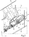
- an exemplary image 15 of one of the cameras 3, 4, 5, 6 is shown in Fig. 2 . As is apparent from Fig.
- a roadway 16 is depicted in the image 15, on which a target object 17 is located and for example moves relatively to the motor vehicle 1.
- the target object 17 is a motor vehicle.
- the methods already known from the prior art can be used, such as for example feature detection (for example FAST points or Harris points) in combination with clustering (for example DBSCAN or k-means), a so-called "blob" detection (for example LoG, DoG, DoH) or another algorithm, such as for example the AdaBoost.
- feature detection for example FAST points or Harris points
- clustering for example DBSCAN or k-means
- blob detection for example LoG, DoG, DoH
- AdaBoost AdaBoost
- the target object 17 can then also be tracked over the sequence of the images, for example by means of the Lukas Kanade method.
- an associated feature 18' can be detected in a subsequent image.
- feature pairs 18, 18' are formed.
- the features 18' are no longer in the same position in the image frame as the features 18.
- An optical flow vector 19 is respectively determined for each feature 18 of the target object 17 by means of the image processing device 13, which connects the feature 18 to the associated feature 18' from the subsequent image and is defined by its length on the one hand and by its direction on the other hand.
- the flow vector 19 characterizes the direction of movement and the speed of movement of the respective characteristic feature 18.
- a reference point 20 is found in the image 15, which is then taken as a basis for determining a distance of the target object 17 from the motor vehicle 1 and/or determining a relative speed between target object 17 and motor vehicle 1.
- this reference point 20 also known under the designation "ground point”
- a baseline 21 is defined, which is in a transition area 22 from the target object 17 to the roadway 16 and extends along this transition area 22, thus at the intersection between target object 17 and roadway 16.
- the exact determination of the baseline 21 and thus of the transition area 22 is configured as follows: First, an orientation of the baseline 21 in the image 15 is determined, i.e.
- a histogram 23 according to Fig. 5 is provided. To this, a plurality of intervals of values 24 is defined. Then, it is examined to each flow vector 19 of the target object 17, in which one of the intervals of values 24 the directional value of the respective flow vector 19 falls. Thus, the number N of the directional values D of the flow vectors 19 is counted to each interval of values 24, which are within the respective interval of values 24. Then, a main interval 25 is defined, which has the greatest number N of directional values D.
- a range 26 is defined around this main interval 25, which for example includes the three nearest intervals of values 24 on both sides of the main interval 25.
- the range 26 can be defined using a fitting function, such as Gaussian or parabolic function, for instance.
- an average value is calculated from the directional values D located in the range 26.
- weighting of the directional values D can optionally also be performed such that the directional values D of the flow vectors 19 are each multiplied by a weighting factor, which depends on in which one of the intervals of values 24 the respective directional value D is located.
- the greatest weighting factor can be selected for the main interval 25.
- the weighting factor can be proportional to the number N in the respective interval of values 24.
- the peak of the histogram could be used, which is also significantly less computationally expensive, albeit less accurate.
- the mentioned average value is used as the orientation ⁇ of the baseline 21 according to Fig. 2 .
- an auxiliary line 27 is defined according to Fig. 2 , which for example extends over the upper left corner of the image 15 and - generally speaking - is above the target object 17.
- distances 28 between this straight auxiliary line 27 on the one hand and the characteristic features 18 of the target object 17 on the other hand are determined.
- That characteristic feature 29, which is in the greatest distance to the auxiliary line 27, is designated as a ground feature, i.e. a feature of the target object 17, which is closest to the roadway 16 and thus represents an exterior feature in the direction perpendicular to the orientation ⁇ .
- the position of the baseline 21 is then defined by the ground feature 29 such that the baseline 21 extends through this ground feature 29.
- the auxiliary line 27 is displaced towards the ground feature 29.
- a straight and vertical bounding line 30 is defined, which extends parallel to the y axis of the image frame.
- this bounding line 30 extends through a feature 31 of the target object 17, which represents an exterior feature of the target object 17 in x direction and thus in the direction perpendicular to the bounding line 30 and therefore is located outermost.
- This feature 31 can also be referred to as "farther-most feature”. This feature 31 is closest to the camera of the motor vehicle 1 - viewed in x direction.
- the reference point 20 of the image 15 is then defined as the intersection of the baseline 21 with the bounding line 30.
- the orientation ⁇ of the baseline 21 can also be determined based on a main extension direction 32 of the roadway 16.
- the main extension direction 32 of the roadway 16 can first be detected based on the image 15.
- the direction 32 of the roadway 16 can be determined by a method such as Hough Transform, whenever visible and easily discernible.
- a flow diagram of the above described method is shown in Fig. 4 .
- the filtering of the directional values D of the flow vectors 19 is effected by means of the histogram 23, as already explained above.
- the average value of the selected directional values D is calculated.
- the image processing device 13 determines the orientation ⁇ of the baseline 21, wherein the orientation ⁇ is equal to the average value.
- the auxiliary line 27 is defined in the corner of the image 15, wherein the auxiliary line 27 has the orientation ⁇ . According to step S5, then, the maximum distance 28 and thus the ground feature 29 is found.
- step S6 The provision of the baseline 21 is then effected in a further step S6, namely such that the baseline 21 is a straight line, which has the orientation ⁇ and extends through the ground feature 29.
- step S7 the bounding line 30 is defined.
- the reference point 20 is then determined as the intersection of the baseline 21 with the bounding line 30 according to step S8.
- the distance of the target object 17 (of the reference point 20) from the motor vehicle 1 and/or the relative speed (based on multiple images 15) can be determined.
Landscapes
- Engineering & Computer Science (AREA)
- Physics & Mathematics (AREA)
- General Physics & Mathematics (AREA)
- Computer Vision & Pattern Recognition (AREA)
- Theoretical Computer Science (AREA)
- Electromagnetism (AREA)
- Radar, Positioning & Navigation (AREA)
- Remote Sensing (AREA)
- Multimedia (AREA)
- Image Analysis (AREA)
- Traffic Control Systems (AREA)
- Image Processing (AREA)
Claims (10)
- Procédé destiné à déterminer une distance actuelle et/ou une vitesse actuelle d'un objet cible (17) par rapport à un véhicule à moteur (1) sur la base d'au moins une image (15) de l'objet cible (17), dans lequel l'image (15) est obtenue au moyen d'une caméra (3, 4, 5, 6) du véhicule à moteur (1), dans lequel des éléments caractéristiques (18) de l'objet cible (17) sont extraits de l'image (15) et un point de référence (20) associé à l'objet cible (17) est déterminé sur la base des éléments caractéristiques (18) pour déterminer la distance et/ou la vitesse, et dans lequel la distance et/ou la vitesse sont déterminées sur la base du point de référence (20),
caractérisé en ce que
sur la base des éléments caractéristiques (18), une ligne de base (21) sous la forme d'une droite est déterminée dans l'image (15), laquelle se trouve dans une zone de transition (22) entre l'objet cible (17) représenté et une surface de sol (16) représentée dans l'image (15), et un point situé sur la ligne de base (21) est déterminé comme le point de référence (20), tandis que la ligne de base (21) est définie par une orientation (α), qui correspond à une direction de déplacement de l'objet cible (17) sur une séquence d'images (15) et/ou à une direction principale de prolongement (32) d'une chaussée (16) détectée dans l'image (15), et les éléments caractéristiques (18) de l'objet cible (17) sont suivis sur une séquence d'images (15) et des vecteurs de flux optique (19) respectifs y sont déterminés pour chacun des éléments caractéristiques (18), vecteurs dont les valeurs directionnelles (D) caractérisent une direction de déplacement de l'élément respectif (18) sur la séquence, l'orientation (α) de la ligne de base (21) étant déterminée en fonction des valeurs directionnelles (D) des vecteurs de flux optique (19). - Procédé selon la revendication 1,
caractérisé en ce que
un sous-ensemble des valeurs directionnelles (D) est sélectionné parmi les valeurs directionnelles (D) des vecteurs de flux optique (19) au moyen d'un filtrage et l'orientation (α) de la ligne de base (21) est déterminée en fonction du sous-ensemble sélectionné des valeurs directionnelles (D). - Procédé selon la revendication 2,
caractérisé en ce que
le filtrage est effectué au moyen d'un histogramme (23) . - Procédé selon la revendication 3,
caractérisé en ce que
pour obtenir l'histogramme (23), une pluralité d'intervalles de valeurs (24) est définie pour les valeurs directionnelles (D), et le nombre (N) des valeurs directionnelles (D) qui sont à l'intérieur de l'intervalle de valeurs (24) respectif est déterminé pour chaque intervalle de valeurs (24), dans lequel le filtrage comporte la détection d'un intervalle principal (25) qui comporte le plus grand nombre (N) des valeurs directionnelles (D), et pour le sous-ensemble destiné à déterminer l'orientation (α) de la ligne de base (21), seules sont sélectionnées les valeurs directionnelles (D) qui se trouvent dans l'intervalle principal (25), en particulier dans l'intervalle principal (25) et également dans des intervalles de valeurs (24) prédéfinis autour de l'intervalle principal (25). - Procédé selon l'une quelconque des revendications 2 à 4,
caractérisé en ce que
une valeur moyenne est calculée à partir du sous-ensemble sélectionné des valeurs directionnelles (D) comme l'orientation (α) de la ligne de base (21). - Procédé selon l'une quelconque des revendications précédentes,
caractérisé en ce que
dans la détermination de la ligne de base (21), d'abord une orientation (α) de la ligne de base (21) et ensuite une position de la ligne de base (21) dans l'image (15) sont déterminées, dans lequel la détermination de la position comporte la détection d'un élément (18) parmi les éléments caractéristiques (18) en tant qu'élément de sol (29), qui représente un élément extérieur (18) de l'objet cible (17) dans la direction perpendiculaire à l'orientation (α) déjà déterminée de la ligne de base (21), et la position de la ligne de base (21) est déterminée de telle sorte que la ligne de base (21) passe par l'élément de sol (29). - Procédé selon l'une quelconque des revendications précédentes,
caractérisé en ce que
le point de référence (20) est déterminé comme une intersection entre la ligne de base (21) et une ligne de délimitation latérale (30), qui délimite latéralement l'objet cible (17) dans l'image (15). - Procédé selon la revendication 7,
caractérisé en ce que
la ligne de délimitation (30) est une ligne orientée verticalement dans l'image (15), qui passe par un élément caractéristique (31) qui représente un élément extérieur (18) de l'objet cible (17) dans la direction perpendiculaire à la ligne de délimitation verticale (30). - Système de caméra (2) pour un véhicule à moteur (1) comportant une caméra (3, 4, 5, 6) destinée à obtenir une image (15) d'une région environnementale (9, 10, 11, 12) du véhicule à moteur (1) et comportant un dispositif de traitement d'images (13) qui est adapté pour effectuer un procédé selon l'une quelconque des revendications précédentes.
- Véhicule à moteur (1) comportant un système de caméra (2) selon la revendication 9.
Applications Claiming Priority (1)
| Application Number | Priority Date | Filing Date | Title |
|---|---|---|---|
| DE201310012930 DE102013012930A1 (de) | 2013-08-02 | 2013-08-02 | Verfahren zum Bestimmen eines aktuellen Abstands und/oder einer aktuellen Geschwindigkeit eines Zielobjekts anhand eines Referenzpunkts in einem Kamerabild, Kamerasystem und Kraftfahrzeug |
Publications (2)
| Publication Number | Publication Date |
|---|---|
| EP2833096A1 EP2833096A1 (fr) | 2015-02-04 |
| EP2833096B1 true EP2833096B1 (fr) | 2018-10-31 |
Family
ID=51260682
Family Applications (1)
| Application Number | Title | Priority Date | Filing Date |
|---|---|---|---|
| EP14179315.8A Active EP2833096B1 (fr) | 2013-08-02 | 2014-07-31 | Procédé permettant de déterminer une distance actuelle et/ou une vitesse actuelle d'un objet cible basé sur un point de référence dans une image de caméra, système de caméra et véhicule à moteur |
Country Status (3)
| Country | Link |
|---|---|
| US (1) | US11236991B2 (fr) |
| EP (1) | EP2833096B1 (fr) |
| DE (1) | DE102013012930A1 (fr) |
Families Citing this family (10)
| Publication number | Priority date | Publication date | Assignee | Title |
|---|---|---|---|---|
| MY183913A (en) * | 2016-10-13 | 2021-03-17 | Nissan Motor | Self position estimation method and self position estimation device |
| US10949996B2 (en) * | 2018-01-16 | 2021-03-16 | Aisin Seiki Kabushiki Kaisha | Self-position estimation apparatus |
| FR3080702A1 (fr) * | 2018-04-25 | 2019-11-01 | Valeo Schalter Und Sensoren Gmbh | Estimation de la distance separant un vehicule automobile d'objets detectes par traitement d'images capturees depuis le vehicule automobile |
| US10863112B1 (en) * | 2019-09-26 | 2020-12-08 | Plantronics, Inc. | Smoothing image transitions when changing views |
| CN110824188B (zh) * | 2019-10-17 | 2022-10-04 | 浙江大华技术股份有限公司 | 高速公路车辆的测速方法、装置、编解码器及存储装置 |
| DE102019129101A1 (de) * | 2019-10-29 | 2021-04-29 | Connaught Electronics Ltd. | Verfahren und System zum Schätzen eines Begrenzungsrahmens, der ein Zielfahrzeug einschließt |
| US11715277B2 (en) * | 2020-06-23 | 2023-08-01 | Tusimple, Inc. | Perception system for autonomous vehicles |
| US11210533B1 (en) | 2020-08-09 | 2021-12-28 | Phantom AI, Inc. | Method of predicting trajectory of vehicle |
| KR20220037531A (ko) * | 2020-09-17 | 2022-03-25 | 현대자동차주식회사 | 차량 및 그 제어방법 |
| DE102022112318B3 (de) | 2022-05-17 | 2023-08-03 | Audi Aktiengesellschaft | Verfahren zur Ermittlung einer Ausdehnungsinformation eines Zielobjekts, Kraftfahrzeug, Computerprogramm und elektronisch lesbarer Datenträger |
Family Cites Families (20)
| Publication number | Priority date | Publication date | Assignee | Title |
|---|---|---|---|---|
| JP3307335B2 (ja) * | 1998-07-22 | 2002-07-24 | 日本電気株式会社 | 車両領域検出装置及び車両領域検定方法 |
| JP3596314B2 (ja) * | 1998-11-02 | 2004-12-02 | 日産自動車株式会社 | 物体端の位置計測装置および移動体の通行判断装置 |
| JP4800455B2 (ja) * | 1999-02-19 | 2011-10-26 | 富士通株式会社 | 車速計測方法および装置 |
| US6535114B1 (en) * | 2000-03-22 | 2003-03-18 | Toyota Jidosha Kabushiki Kaisha | Method and apparatus for environment recognition |
| JP3833614B2 (ja) * | 2001-02-19 | 2006-10-18 | 本田技研工業株式会社 | 目標認識装置および目標認識方法 |
| JP3759429B2 (ja) * | 2001-05-23 | 2006-03-22 | 株式会社東芝 | 障害物検出装置及びその方法 |
| JP2002372417A (ja) * | 2001-06-15 | 2002-12-26 | Mitsubishi Electric Corp | 物体位置・速度計測処理装置 |
| JP3879740B2 (ja) * | 2004-02-13 | 2007-02-14 | 日産自動車株式会社 | 道路領域検出装置 |
| US7190282B2 (en) * | 2004-03-26 | 2007-03-13 | Mitsubishi Jidosha Kogyo Kabushiki Kaisha | Nose-view monitoring apparatus |
| JP4328692B2 (ja) * | 2004-08-11 | 2009-09-09 | 国立大学法人東京工業大学 | 物体検出装置 |
| JP4938351B2 (ja) * | 2006-05-16 | 2012-05-23 | トヨタ自動車株式会社 | 車両用測位情報更新装置 |
| JP2009129001A (ja) * | 2007-11-20 | 2009-06-11 | Sanyo Electric Co Ltd | 運転支援システム、車両、立体物領域推定方法 |
| US8812226B2 (en) * | 2009-01-26 | 2014-08-19 | GM Global Technology Operations LLC | Multiobject fusion module for collision preparation system |
| JP4788798B2 (ja) * | 2009-04-23 | 2011-10-05 | トヨタ自動車株式会社 | 物体検出装置 |
| US9547795B2 (en) * | 2011-04-25 | 2017-01-17 | Magna Electronics Inc. | Image processing method for detecting objects using relative motion |
| JP6058256B2 (ja) * | 2011-06-13 | 2017-01-11 | アルパイン株式会社 | 車載カメラ姿勢検出装置および方法 |
| JP5663411B2 (ja) * | 2011-06-14 | 2015-02-04 | 本田技研工業株式会社 | 測距装置 |
| US9341740B1 (en) * | 2012-02-13 | 2016-05-17 | See Scan, Inc. | Optical ground tracking apparatus, systems, and methods |
| JP5832341B2 (ja) * | 2012-03-09 | 2015-12-16 | 株式会社トプコン | 動画処理装置、動画処理方法および動画処理用のプログラム |
| US20130322697A1 (en) * | 2012-05-31 | 2013-12-05 | Hexagon Technology Center Gmbh | Speed Calculation of a Moving Object based on Image Data |
-
2013
- 2013-08-02 DE DE201310012930 patent/DE102013012930A1/de not_active Withdrawn
-
2014
- 2014-07-31 EP EP14179315.8A patent/EP2833096B1/fr active Active
- 2014-08-01 US US14/449,200 patent/US11236991B2/en active Active
Non-Patent Citations (1)
| Title |
|---|
| None * |
Also Published As
| Publication number | Publication date |
|---|---|
| DE102013012930A1 (de) | 2015-02-05 |
| US11236991B2 (en) | 2022-02-01 |
| US20150035973A1 (en) | 2015-02-05 |
| EP2833096A1 (fr) | 2015-02-04 |
Similar Documents
| Publication | Publication Date | Title |
|---|---|---|
| US11236991B2 (en) | Method for determining a current distance and/or a current speed of a target object based on a reference point in a camera image, camera system and motor vehicle | |
| US11679635B2 (en) | Vehicular trailer hitching assist system with coupler height and location estimation | |
| US11447070B2 (en) | Method for determining misalignment of a vehicular camera | |
| US20220189180A1 (en) | Vehicular vision system that determines distance to an object | |
| US11648877B2 (en) | Method for detecting an object via a vehicular vision system | |
| EP3007099B1 (fr) | Système de reconnaissance d'image pour véhicule et procédé correspondant | |
| CN101303735B (zh) | 探测车辆盲点区域内运动物体的方法及盲点探测装置 | |
| JP7025912B2 (ja) | 車載環境認識装置 | |
| CN107845104B (zh) | 一种检测超车车辆的方法、相关处理系统、超车车辆检测系统以及车辆 | |
| EP1671216B1 (fr) | Detection d'objets en mouvement faisant appel a une vision artificielle en conditions de faible d'eclairage | |
| KR101692628B1 (ko) | 관심영역을 이용하여 차량의 후방 좌우 옆 차선 영역을 감지하는 방법 및 이를 이용한 차량용 영상 모니터링 시스템 | |
| US10276040B2 (en) | Method for tracking a target vehicle approaching a motor vehicle by means of a camera system of the motor vehicle, camera system and motor vehicle | |
| US20170297488A1 (en) | Surround view camera system for object detection and tracking | |
| JP3596314B2 (ja) | 物体端の位置計測装置および移動体の通行判断装置 | |
| EP3545464B1 (fr) | Dispositif de traitement d'informations, dispositif d'imagerie, système de commande d'équipement, objet mobile, procédé de traitement d'informations et support d'enregistrement lisible par ordinateur | |
| EP2928178B1 (fr) | Dispositif de commande embarqué | |
| CN110203210A (zh) | 一种车道偏离预警方法、终端设备及存储介质 | |
| CN108162858B (zh) | 车载监控装置及其方法 | |
| US12400353B2 (en) | Vehicular vision system with object detection and identification with adaptive thresholding | |
| US9934428B2 (en) | Method and system for detecting pedestrians | |
| JP7379268B2 (ja) | 画像処理装置 | |
| KR20230127436A (ko) | 근거리 차량 검출 장치 및 그 방법 | |
| WO2014095779A1 (fr) | Procédé permettant de différencier les caractéristiques d'un objet cible et les caractéristiques de terrain dans une image d'une caméra, système de caméra pour véhicule à moteur, et véhicule à moteur | |
| KR20180040313A (ko) | 단안 카메라를 이용한 차로 경계면 검출장치 및 방법 |
Legal Events
| Date | Code | Title | Description |
|---|---|---|---|
| 17P | Request for examination filed |
Effective date: 20140731 |
|
| AK | Designated contracting states |
Kind code of ref document: A1 Designated state(s): AL AT BE BG CH CY CZ DE DK EE ES FI FR GB GR HR HU IE IS IT LI LT LU LV MC MK MT NL NO PL PT RO RS SE SI SK SM TR |
|
| AX | Request for extension of the european patent |
Extension state: BA ME |
|
| PUAI | Public reference made under article 153(3) epc to a published international application that has entered the european phase |
Free format text: ORIGINAL CODE: 0009012 |
|
| R17P | Request for examination filed (corrected) |
Effective date: 20150804 |
|
| RBV | Designated contracting states (corrected) |
Designated state(s): AL AT BE BG CH CY CZ DE DK EE ES FI FR GB GR HR HU IE IS IT LI LT LU LV MC MK MT NL NO PL PT RO RS SE SI SK SM TR |
|
| GRAP | Despatch of communication of intention to grant a patent |
Free format text: ORIGINAL CODE: EPIDOSNIGR1 |
|
| STAA | Information on the status of an ep patent application or granted ep patent |
Free format text: STATUS: GRANT OF PATENT IS INTENDED |
|
| INTG | Intention to grant announced |
Effective date: 20180528 |
|
| GRAS | Grant fee paid |
Free format text: ORIGINAL CODE: EPIDOSNIGR3 |
|
| GRAA | (expected) grant |
Free format text: ORIGINAL CODE: 0009210 |
|
| STAA | Information on the status of an ep patent application or granted ep patent |
Free format text: STATUS: THE PATENT HAS BEEN GRANTED |
|
| AK | Designated contracting states |
Kind code of ref document: B1 Designated state(s): AL AT BE BG CH CY CZ DE DK EE ES FI FR GB GR HR HU IE IS IT LI LT LU LV MC MK MT NL NO PL PT RO RS SE SI SK SM TR |
|
| REG | Reference to a national code |
Ref country code: CH Ref legal event code: EP Ref country code: GB Ref legal event code: FG4D |
|
| REG | Reference to a national code |
Ref country code: AT Ref legal event code: REF Ref document number: 1059921 Country of ref document: AT Kind code of ref document: T Effective date: 20181115 |
|
| REG | Reference to a national code |
Ref country code: DE Ref legal event code: R096 Ref document number: 602014034988 Country of ref document: DE |
|
| REG | Reference to a national code |
Ref country code: IE Ref legal event code: FG4D |
|
| REG | Reference to a national code |
Ref country code: NL Ref legal event code: MP Effective date: 20181031 |
|
| REG | Reference to a national code |
Ref country code: LT Ref legal event code: MG4D |
|
| REG | Reference to a national code |
Ref country code: AT Ref legal event code: MK05 Ref document number: 1059921 Country of ref document: AT Kind code of ref document: T Effective date: 20181031 |
|
| PG25 | Lapsed in a contracting state [announced via postgrant information from national office to epo] |
Ref country code: AT Free format text: LAPSE BECAUSE OF FAILURE TO SUBMIT A TRANSLATION OF THE DESCRIPTION OR TO PAY THE FEE WITHIN THE PRESCRIBED TIME-LIMIT Effective date: 20181031 Ref country code: LV Free format text: LAPSE BECAUSE OF FAILURE TO SUBMIT A TRANSLATION OF THE DESCRIPTION OR TO PAY THE FEE WITHIN THE PRESCRIBED TIME-LIMIT Effective date: 20181031 Ref country code: IS Free format text: LAPSE BECAUSE OF FAILURE TO SUBMIT A TRANSLATION OF THE DESCRIPTION OR TO PAY THE FEE WITHIN THE PRESCRIBED TIME-LIMIT Effective date: 20190228 Ref country code: HR Free format text: LAPSE BECAUSE OF FAILURE TO SUBMIT A TRANSLATION OF THE DESCRIPTION OR TO PAY THE FEE WITHIN THE PRESCRIBED TIME-LIMIT Effective date: 20181031 Ref country code: NO Free format text: LAPSE BECAUSE OF FAILURE TO SUBMIT A TRANSLATION OF THE DESCRIPTION OR TO PAY THE FEE WITHIN THE PRESCRIBED TIME-LIMIT Effective date: 20190131 Ref country code: FI Free format text: LAPSE BECAUSE OF FAILURE TO SUBMIT A TRANSLATION OF THE DESCRIPTION OR TO PAY THE FEE WITHIN THE PRESCRIBED TIME-LIMIT Effective date: 20181031 Ref country code: BG Free format text: LAPSE BECAUSE OF FAILURE TO SUBMIT A TRANSLATION OF THE DESCRIPTION OR TO PAY THE FEE WITHIN THE PRESCRIBED TIME-LIMIT Effective date: 20190131 Ref country code: PL Free format text: LAPSE BECAUSE OF FAILURE TO SUBMIT A TRANSLATION OF THE DESCRIPTION OR TO PAY THE FEE WITHIN THE PRESCRIBED TIME-LIMIT Effective date: 20181031 Ref country code: ES Free format text: LAPSE BECAUSE OF FAILURE TO SUBMIT A TRANSLATION OF THE DESCRIPTION OR TO PAY THE FEE WITHIN THE PRESCRIBED TIME-LIMIT Effective date: 20181031 Ref country code: LT Free format text: LAPSE BECAUSE OF FAILURE TO SUBMIT A TRANSLATION OF THE DESCRIPTION OR TO PAY THE FEE WITHIN THE PRESCRIBED TIME-LIMIT Effective date: 20181031 |
|
| PG25 | Lapsed in a contracting state [announced via postgrant information from national office to epo] |
Ref country code: PT Free format text: LAPSE BECAUSE OF FAILURE TO SUBMIT A TRANSLATION OF THE DESCRIPTION OR TO PAY THE FEE WITHIN THE PRESCRIBED TIME-LIMIT Effective date: 20190301 Ref country code: NL Free format text: LAPSE BECAUSE OF FAILURE TO SUBMIT A TRANSLATION OF THE DESCRIPTION OR TO PAY THE FEE WITHIN THE PRESCRIBED TIME-LIMIT Effective date: 20181031 Ref country code: AL Free format text: LAPSE BECAUSE OF FAILURE TO SUBMIT A TRANSLATION OF THE DESCRIPTION OR TO PAY THE FEE WITHIN THE PRESCRIBED TIME-LIMIT Effective date: 20181031 Ref country code: SE Free format text: LAPSE BECAUSE OF FAILURE TO SUBMIT A TRANSLATION OF THE DESCRIPTION OR TO PAY THE FEE WITHIN THE PRESCRIBED TIME-LIMIT Effective date: 20181031 Ref country code: GR Free format text: LAPSE BECAUSE OF FAILURE TO SUBMIT A TRANSLATION OF THE DESCRIPTION OR TO PAY THE FEE WITHIN THE PRESCRIBED TIME-LIMIT Effective date: 20190201 Ref country code: RS Free format text: LAPSE BECAUSE OF FAILURE TO SUBMIT A TRANSLATION OF THE DESCRIPTION OR TO PAY THE FEE WITHIN THE PRESCRIBED TIME-LIMIT Effective date: 20181031 |
|
| PG25 | Lapsed in a contracting state [announced via postgrant information from national office to epo] |
Ref country code: DK Free format text: LAPSE BECAUSE OF FAILURE TO SUBMIT A TRANSLATION OF THE DESCRIPTION OR TO PAY THE FEE WITHIN THE PRESCRIBED TIME-LIMIT Effective date: 20181031 Ref country code: IT Free format text: LAPSE BECAUSE OF FAILURE TO SUBMIT A TRANSLATION OF THE DESCRIPTION OR TO PAY THE FEE WITHIN THE PRESCRIBED TIME-LIMIT Effective date: 20181031 Ref country code: CZ Free format text: LAPSE BECAUSE OF FAILURE TO SUBMIT A TRANSLATION OF THE DESCRIPTION OR TO PAY THE FEE WITHIN THE PRESCRIBED TIME-LIMIT Effective date: 20181031 |
|
| REG | Reference to a national code |
Ref country code: DE Ref legal event code: R097 Ref document number: 602014034988 Country of ref document: DE |
|
| PG25 | Lapsed in a contracting state [announced via postgrant information from national office to epo] |
Ref country code: RO Free format text: LAPSE BECAUSE OF FAILURE TO SUBMIT A TRANSLATION OF THE DESCRIPTION OR TO PAY THE FEE WITHIN THE PRESCRIBED TIME-LIMIT Effective date: 20181031 Ref country code: SK Free format text: LAPSE BECAUSE OF FAILURE TO SUBMIT A TRANSLATION OF THE DESCRIPTION OR TO PAY THE FEE WITHIN THE PRESCRIBED TIME-LIMIT Effective date: 20181031 Ref country code: SM Free format text: LAPSE BECAUSE OF FAILURE TO SUBMIT A TRANSLATION OF THE DESCRIPTION OR TO PAY THE FEE WITHIN THE PRESCRIBED TIME-LIMIT Effective date: 20181031 Ref country code: EE Free format text: LAPSE BECAUSE OF FAILURE TO SUBMIT A TRANSLATION OF THE DESCRIPTION OR TO PAY THE FEE WITHIN THE PRESCRIBED TIME-LIMIT Effective date: 20181031 |
|
| PLBE | No opposition filed within time limit |
Free format text: ORIGINAL CODE: 0009261 |
|
| STAA | Information on the status of an ep patent application or granted ep patent |
Free format text: STATUS: NO OPPOSITION FILED WITHIN TIME LIMIT |
|
| 26N | No opposition filed |
Effective date: 20190801 |
|
| PG25 | Lapsed in a contracting state [announced via postgrant information from national office to epo] |
Ref country code: SI Free format text: LAPSE BECAUSE OF FAILURE TO SUBMIT A TRANSLATION OF THE DESCRIPTION OR TO PAY THE FEE WITHIN THE PRESCRIBED TIME-LIMIT Effective date: 20181031 |
|
| PG25 | Lapsed in a contracting state [announced via postgrant information from national office to epo] |
Ref country code: MC Free format text: LAPSE BECAUSE OF FAILURE TO SUBMIT A TRANSLATION OF THE DESCRIPTION OR TO PAY THE FEE WITHIN THE PRESCRIBED TIME-LIMIT Effective date: 20181031 |
|
| REG | Reference to a national code |
Ref country code: CH Ref legal event code: PL |
|
| PG25 | Lapsed in a contracting state [announced via postgrant information from national office to epo] |
Ref country code: TR Free format text: LAPSE BECAUSE OF FAILURE TO SUBMIT A TRANSLATION OF THE DESCRIPTION OR TO PAY THE FEE WITHIN THE PRESCRIBED TIME-LIMIT Effective date: 20181031 |
|
| REG | Reference to a national code |
Ref country code: BE Ref legal event code: MM Effective date: 20190731 |
|
| PG25 | Lapsed in a contracting state [announced via postgrant information from national office to epo] |
Ref country code: LI Free format text: LAPSE BECAUSE OF NON-PAYMENT OF DUE FEES Effective date: 20190731 Ref country code: BE Free format text: LAPSE BECAUSE OF NON-PAYMENT OF DUE FEES Effective date: 20190731 Ref country code: CH Free format text: LAPSE BECAUSE OF NON-PAYMENT OF DUE FEES Effective date: 20190731 Ref country code: LU Free format text: LAPSE BECAUSE OF NON-PAYMENT OF DUE FEES Effective date: 20190731 |
|
| PG25 | Lapsed in a contracting state [announced via postgrant information from national office to epo] |
Ref country code: IE Free format text: LAPSE BECAUSE OF NON-PAYMENT OF DUE FEES Effective date: 20190731 |
|
| PG25 | Lapsed in a contracting state [announced via postgrant information from national office to epo] |
Ref country code: CY Free format text: LAPSE BECAUSE OF FAILURE TO SUBMIT A TRANSLATION OF THE DESCRIPTION OR TO PAY THE FEE WITHIN THE PRESCRIBED TIME-LIMIT Effective date: 20181031 |
|
| PG25 | Lapsed in a contracting state [announced via postgrant information from national office to epo] |
Ref country code: MT Free format text: LAPSE BECAUSE OF FAILURE TO SUBMIT A TRANSLATION OF THE DESCRIPTION OR TO PAY THE FEE WITHIN THE PRESCRIBED TIME-LIMIT Effective date: 20181031 Ref country code: HU Free format text: LAPSE BECAUSE OF FAILURE TO SUBMIT A TRANSLATION OF THE DESCRIPTION OR TO PAY THE FEE WITHIN THE PRESCRIBED TIME-LIMIT; INVALID AB INITIO Effective date: 20140731 |
|
| PG25 | Lapsed in a contracting state [announced via postgrant information from national office to epo] |
Ref country code: MK Free format text: LAPSE BECAUSE OF FAILURE TO SUBMIT A TRANSLATION OF THE DESCRIPTION OR TO PAY THE FEE WITHIN THE PRESCRIBED TIME-LIMIT Effective date: 20181031 |
|
| P01 | Opt-out of the competence of the unified patent court (upc) registered |
Effective date: 20230528 |
|
| PGFP | Annual fee paid to national office [announced via postgrant information from national office to epo] |
Ref country code: DE Payment date: 20250711 Year of fee payment: 12 |
|
| PGFP | Annual fee paid to national office [announced via postgrant information from national office to epo] |
Ref country code: GB Payment date: 20250723 Year of fee payment: 12 |
|
| PGFP | Annual fee paid to national office [announced via postgrant information from national office to epo] |
Ref country code: FR Payment date: 20250730 Year of fee payment: 12 |