EP2833113B1 - Leckagenerkennungsverfahren, verfahren zur erkennung von wasserleckagen, leckagenerkennungsvorrichtung sowie vorrichtung zur erkennung von wasserleckagen - Google Patents
Leckagenerkennungsverfahren, verfahren zur erkennung von wasserleckagen, leckagenerkennungsvorrichtung sowie vorrichtung zur erkennung von wasserleckagen Download PDFInfo
- Publication number
- EP2833113B1 EP2833113B1 EP12873033.0A EP12873033A EP2833113B1 EP 2833113 B1 EP2833113 B1 EP 2833113B1 EP 12873033 A EP12873033 A EP 12873033A EP 2833113 B1 EP2833113 B1 EP 2833113B1
- Authority
- EP
- European Patent Office
- Prior art keywords
- leakage
- acoustic sensors
- acoustic
- water
- sensors
- Prior art date
- Legal status (The legal status is an assumption and is not a legal conclusion. Google has not performed a legal analysis and makes no representation as to the accuracy of the status listed.)
- Active
Links
Images




Classifications
-
- G—PHYSICS
- G01—MEASURING; TESTING
- G01M—TESTING STATIC OR DYNAMIC BALANCE OF MACHINES OR STRUCTURES; TESTING OF STRUCTURES OR APPARATUS, NOT OTHERWISE PROVIDED FOR
- G01M3/00—Investigating fluid-tightness of structures
- G01M3/02—Investigating fluid-tightness of structures by using fluid or vacuum
- G01M3/04—Investigating fluid-tightness of structures by using fluid or vacuum by detecting the presence of fluid at the leakage point
- G01M3/24—Investigating fluid-tightness of structures by using fluid or vacuum by detecting the presence of fluid at the leakage point using infrasonic, sonic or ultrasonic vibrations
- G01M3/243—Investigating fluid-tightness of structures by using fluid or vacuum by detecting the presence of fluid at the leakage point using infrasonic, sonic or ultrasonic vibrations for pipes
-
- F—MECHANICAL ENGINEERING; LIGHTING; HEATING; WEAPONS; BLASTING
- F17—STORING OR DISTRIBUTING GASES OR LIQUIDS
- F17D—PIPE-LINE SYSTEMS; PIPE-LINES
- F17D5/00—Protection or supervision of installations
- F17D5/02—Preventing, monitoring, or locating loss
- F17D5/06—Preventing, monitoring, or locating loss using electric or acoustic means
Definitions
- the present invention relates to a leakage detection method, a water-leakage detection method, a leakage detection device, and a water-leakage detection device, for a pipe.
- This method is a method in which two acoustic sensors are placed on a pipe so that an approximate spot of a suspected water-leakage is intervened between the two acoustic sensors, signals of water-leakage sounds received by the acoustic sensors are subjected to cross-correlation processing, and a water-leakage position is identified from a difference between arrival times of the water-leakage sounds.
- US 7, 739, 899 B1 relates to method for detection and location of air leaks in a pressure vessel, such as a spacecraft.
- EP 0 697 586 A2 relates to a system for mapping absolute acoustic noise intensity in a three-dimensional acoustic noise field and using three-dimensional absolute noise intensities to infer operational or performance characteristics of components or structures within the monitored field.
- WO 2004/090498 A1 relates to a device for detecting and approximately localizing a leakage in a drinking water supply network.
- EP 2 352 002 A1 relates to a system for remote leak detection and/or path tracking for underground fluid transportation pipelines.
- acoustic sensors are arranged along a pipeline as in a technique described in the above-described patent documents, it is desired to arrange the acoustic sensors at intervals of about 100 m to hundreds of meters, for example, from the relationship of water-leakage sound propagating distance. Since a water-supply pipe or the like is generally buried under the ground, it is realistic that acoustic sensors are placed on a pipeline utilizing existing facilities such as a manhole and the like, from the viewpoint of the labor of construction. However, a manhole and the like are not always present at locations which are convenient to arrange the acoustic sensors. Therefore, arranging sensors at ideal positions is not easy because an extensive construction is required and the like.
- the present invention is intended to provide a leakage detection method, a water-leakage detection method, a leakage detection device, and a water-leakage detection device, for a pipe, with ease of placing sensors, high detection accuracy, and high reliability.
- the leakage detection method of the present invention is a leakage detection method for detecting a leakage from a pipe in which a fluid flows, using a pair of acoustic sensors arranged at a certain distance from each other and a certain distance from a location of the pipe, the method including: an acoustic data acquisition step of performing time synchronization between acoustic sensors configuring the pair of acoustic sensors to acquire acoustic data by the acoustic sensors; a time difference calculation step of determining a difference between arrival times of sounds received by the respective acoustic sensors; a distance difference calculation step of calculating, from the difference between arrival times, a difference between distances from a source of the sounds to the respective acoustic sensors; a hyperbola acquisition step of determining a hyperbola which is a collection of points at each of which a difference in distance from each of the acoustic sensors is constant, with positions of the respective acoustic sensors
- the water-leakage detection method of the present invention is a water-leakage detection method for detecting a water-leakage, the water-leakage detection method including detecting a water-leakage from a conduit using the leakage detection method of the present invention.
- the leakage detection device of the present invention is a leakage detection device for detecting a leakage from a pipe in which a fluid flows, the leakage detection device including: an acoustic data acquisition unit that is a pair of acoustic sensors capable of acquiring acoustic data and being subjected to time synchronization, arranged at a certain distance from each other and a certain distance from a location of the pipe; a time difference calculation unit that determines a difference between arrival times of sounds received by the respective acoustic sensors; a distance difference calculation unit that calculates, from the difference between arrival times, a difference between distances from a source of the sounds to the respective acoustic sensors; a hyperbola acquisition unit that determines a hyperbola which is a collection of points at each of which a difference in distance from each of the acoustic sensors is constant, with positions of the respective acoustic sensors as foci; and a position identification unit that identifies a position of the leakage from an intersection between
- the water-leakage detection device of the present invention is a water-leakage detection device for detecting a water-leakage from a conduit, the water-leakage detection device including: the leakage detection device of the present invention.
- a leakage detection method, a water-leakage detection method, a leakage detection device, and a water-leakage detection device, for a pipe with ease of placing sensors, high detection accuracy, and high reliability is provided according to claims 1 and 7.
- the leakage detection method of the present invention it is preferred that a plurality of the pairs of acoustic sensors are used, in the hyperbola acquisition step, hyperbolas for the respective pairs are determined, and in the position identification step, intersections of the hyperbolas determined for the respective pairs are subjected to weighted averaging to identify a position of the source of the sounds.
- a plurality of the pairs of acoustic sensors are used, in the hyperbola acquisition step, hyperbolas for the respective pairs are determined, and in the position identification step, a position of an intersection on the pipe among intersections of the hyperbolas determined for the respective pairs is determined as a position of the leakage.
- relative time synchronization is performed between the acoustic sensors configuring each of the pairs of acoustic sensors, and absolute time synchronization is performed among the plurality of the pairs of acoustic sensors.
- At least three acoustic sensors are used as a set as substitute for the two acoustic sensors, and in the hyperbola acquisition step, at least three kinds of hyperbolas are determined using, as foci, combinations of two acoustic sensors among the at least three acoustic sensors.
- the leakage detection method of the present invention it is preferred that at least three pairs of acoustic sensors are used, and in the position identification step, the intersections are determined using, as a variable parameter, a sound velocity in a medium in which the sound propagates.
- the leakage detection method of the present invention includes, prior to the time difference calculation step, a determination step of deriving a power spectrum of acoustic data received by the acoustic sensor and comparing the power spectrum with a power spectrum of past acoustic data with no detection of leakage, to determine the presence or absence of a leakage.
- a position of the leakage is identified using intensity ratio data of leakage sounds on the power spectrum of the acoustic data received by the acoustic sensors.
- the acoustic data received by the acoustic sensors are collected for each of combinations of plural sampling rates and plural recording times.
- the leakage detection method of the present invention includes a determination step of determining the presence or absence of a leakage using another acoustic analysis method prior to the time difference calculation step.
- the hyperbola acquisition unit determines hyperbolas for the respective pairs
- the position identification unit subjects intersections of the hyperbolas determined for the respective pairs to weighted averaging to identify a position of the source of the sounds.
- the hyperbola acquisition unit determines hyperbolas for the respective pairs
- the position identification unit determines a position of an intersection on the pipe among intersections of hyperbolas determined for the respective pairs as a position of the leakage.
- relative time synchronization is performed between the acoustic sensors configuring each of the pairs of acoustic sensors, and absolute time synchronization is performed among the plurality of the pairs of acoustic sensors.
- the hyperbola acquisition unit determines at least three kinds of hyperbolas using, as foci, combinations of two acoustic sensors among the at least three acoustic sensors.
- the position identification unit determines the intersections using, as a variable parameter, a sound velocity in a medium in which the sound propagates.
- the leakage detection device of the present invention further includes a determination unit that derives and compares a power spectrum of acoustic data received by the acoustic sensors with a power spectrum of past acoustic data with no detection of leakage to determine the presence or absence of a leakage.
- the position identification unit identifies a position of the leakage using intensity ratio data of leakage sounds on the power spectrum of the acoustic data received by the acoustic sensors.
- the acoustic data acquisition unit collects the acoustic data received by the acoustic sensors for each of combinations of plural sampling rates and plural recording times.
- the leakage detection device of the present invention further includes a determination unit that determines the presence or absence of a leakage using another acoustic analysis unit.
- the detection of a water-leakage spot can be efficiently performed by fixedly arranging acoustic sensors along a pipeline in a net-like fashion, accumulating data regularly collected by these sensors in a server of a processing center to perform automatic detection processing of a water-leakage sound, performing cross-correlation processing between neighborhood sensor data when a water-leakage sound is detected, and placing a system of localization of a water-leakage position.
- the challenge can be found in automatic identification of a water-leakage sound.
- a method in which signals of acoustic sensors are subjected to frequency analysis processing or the like, and the presence or absence of a water-leakage is determined by energy intensity in a water-leakage sound-specific frequency band is considered.
- data are acquired in the quiet of the midnight, there is no guarantee that there are no components of other sound sources other than the water-leakage in the band, and there is a challenge of possibility of raising a false alarm.
- the challenge can be found in time synchronization among different sensors.
- the velocity of acoustic wave that propagates through a solid such as a pipe line is about 3,000 to 6,000 m/s although it depends on a material thereof.
- the time required for an acoustic wave to propagate 1 m is the inverse of this velocity and is thus about 167 to 333 ⁇ s. That is, in order to localize a water-leakage spot by cross-correlation processing with accuracy of about 1 m, it is required to perform the measurement with accuracy of a different between arrival times of water-leakage sounds of around 200 ⁇ s.
- the size of the acoustic data desirably has a length satisfying the time required to listen significantly and is, for example, for 1 minute.
- the data length in the high-speed sampling is long, i.e., the size of the data is really big, and there is a challenge of putting a pressure on the wireless network.
- the leakage detection method, the water-leakage detection method, the leakage detection device, and the water-leakage detection device, of the present invention are described in detail below with reference to examples.
- the present invention is not limited by the following embodiments.
- the identical parts are denoted by the identical reference numerals.
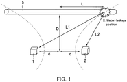
- FIG. 1 is a conceptual diagram describing a leakage detection method of the first embodiment according to the present invention.
- two acoustic sensors 1 and 2 are arranged at a certain distance from each other and at a certain distance from a location of a pipe 5.
- a fluid flows in the pipe 5.
- a leakage from the pipe 5 is detected as mentioned below using the two acoustic sensors as a pair.
- the pipe 5 is a conduit laid under the ground, and the fluid is water is described.
- the present invention is not limited thereby.
- the following steps are performed.
- the acoustic sensors 1 and 2 configuring the pair of acoustic sensors are subjected to time synchronization, and acoustic data are acquired (acoustic data acquisition step).
- a difference between arrival time of sound acquired by the acoustic sensor 1 and arrival time of sound acquired by the acoustic sensor 2 is determined (time difference calculation step). From the obtained difference between arrival times, a difference between a distance from the source of the sounds to the acoustic sensor 1 and a distance from the source of the sounds to the acoustic sensor 2 is calculated (distance difference calculation step).
- a hyperbola which is a collection of points at each of which a difference in distance from each of the acoustic sensors 1 and 2 is constant, with positions of the respective acoustic sensors 1 and 2 as foci, is determined (hyperbola acquisition step). Subsequently, a position of the leakage is determined from an intersection between the pipe 5 and the hyperbola (position identification step).
- acoustic sensors are arranged at a certain distance from a location of the pipe.
- the acoustic sensors can be placed on the side walk of the surface of the ground without being directly in contact with a conduit that is under the ground, for example.
- a water-leakage sound propagates through a conduit and of course propagates under the ground.
- the water-leakage sound can be listened on the surface of the ground.
- sensors can be placed at ideal locations without a limitation to a manhole position and the like.
- by placing sensors not under the ground but on the ground it becomes easier to place a wireless antenna for collecting data, radiation characteristics of an electric wave are improved, and a communicable area in data collection described below is expanded.
- a leakage position between the sensors can be only localized.
- the leakage sound is subjected to cross-correlation processing, and a leakage position can be localized in a wide range. Specifically, FIG.
- the water-leakage position can be localized.
- the position can be localized.
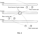
- FIG. 2 is a conceptual diagram describing a leakage detection method of the second embodiment according to the present invention.
- plural pairs of acoustic sensors are used.
- FIG. 2 shows the case of using three pairs of acoustic sensors (in FIG. 2 , each pair of acoustic sensors is referred to as a "wave receiver pair").
- Hyperbolas for the respective pairs can be obtained as in the first embodiment.
- a water- leakage position can be identified by determining intersections of the obtained plural hyperbolas and the pipeline.
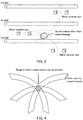
- the sounds received by the acoustic sensors are water-leakage sounds or sounds from sound sources other than the water-leakage sounds. This is because, for example, as shown in FIG. 3 , when intersections of hyperbolas are not present on the pipelines in the course of determining intersections of the plural hyperbolas and the pipelines, it can be reasonably determined that the sources of the sounds are not derived from a water-leakage, and the sounds can be excluded from objects to be processed.
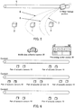
- a range in which a sound source can be present is a band-like region in which a hyperbola has a width.
- a source of the sounds is present in a part in which band-like regions intersect with each other as shown in FIG. 4 .
- the intersection can be searched for by obtaining a solution using a sound velocity in a medium in which the sound propagates as a variable parameter.
- FIG. 5 is a conceptual diagram describing a leakage detection method of the third embodiment according to the present invention.
- three acoustic sensors 1, 2, and 3 are used as a set and are arranged at a certain distance from one another and a certain distance from a location of a pipe 5.
- three combinations including a combination of acoustic sensors 1 and 2, a combination of acoustic sensors 1 and 3, and a combination of acoustic sensors 2 and 3 can be selected.
- three hyperbolas including a hyperbola 6 having the acoustic sensors 1 and 2 as foci, a hyperbola 7 having the acoustic sensors 1 and 3 as foci, and a hyperbola 8 having the acoustic sensors 2 and 3 as foci can be drawn.
- a spot at which three intersections formed by the three hyperbolas converge it becomes possible to localize the position of a water-leakage spot and prevent an error alarm without using plural pairs of acoustic sensors.
- three acoustic sensors are used as a set in the present embodiment, three or more acoustic sensors may be used as a set.
- the fourth embodiment is an example of a water-leakage detection system using a water-leakage detection method and a water-leakage detection device of the present invention.
- FIG. 6 is a conceptual diagram of the water-leakage detection system of the present embodiment.
- FIG. 7 shows a configuration example of the system.
- the system is composed of acoustic sensors 10 that is placed on the road and collects water-leakage sounds, a mobile data collection section 20 that is mounted on a vehicle or the like and collects acoustic data by patrolling around the acoustic sensors 10 at the respective places, and a processing center section 30 that performs detection of water-leakage sounds and position localization processing.
- the acoustic sensors 10 are arranged in a net-like fashion along a conduit line by a pair to be subjected to correlation processing used in position localization, for example, at intervals of about several hundreds of meters, so that a water-leakage spot can be planarly detected in a wide range.
- Each acoustic sensor 10 is composed of a wave receiving element section 11 that converts a water-leakage sound that propagates as an oscillatory wave in a pipeline or under the ground into an electrical signal, a signal pre-processing section 12 that digitalizes the electrical signal from the wave receiving element section 11 and compresses and the like data, a signal temporary storage section 13 that temporarily stores acoustic data processed by the signal pre-processing section 12, a ground-side wireless communication section 14 that sends the acoustic data stored in the signal temporary storage section 13 to a mobile data collection section 20, and a time synchronization section 15 that performs internal time synchronization utilizing communication with other acoustic sensors 10 and communication with the mobile data collection section 20.
- acoustic sensors 10 are composed by a pair to be subjected to correlation processing. However, it is required to perform time synchronization by a pair before measurement. Thus, even though the acoustic sensors 10 have the same functional configuration, there are two functions of master and slave.
- the mobile data collection section 20 is composed of a navigation section 21 that guides a direction to each acoustic sensor 10 using a GPS and the like, an on-vehicle side wireless communication section 22 that receives the acoustic data sent from the acoustic sensors 10, and a signal collection section 23 that temporarily stores the received acoustic data.
- the processing center section 30 is composed of a signal post-processing section 31 that subjects the acoustic data transferred from the mobile data collection section 20 via a memory card or the like to processing such as decompressing and filtering, a signal accumulation section 32 that accumulates the processed acoustic data, a water-leakage detection processing section 33 that performs detection processing of a water-leakage sound using the acoustic data processed by the signal post-processing section 31, a sensor position database (DB) section 34 that stores information on position of each acoustic sensor 10 and information on arrangement of conduit, a position localization processing section 35 that determines a position of a water-leakage using the acoustic data of a water-leakage sound detected by the water-leakage detection processing section 33 in combination with the information on position stored in the sensor position DB section 34, and a water-leakage spot display section 36 that displays a spot of the detected water-leakage to an investigator.
- DB sensor position database
- the transfer of the acoustic data between the acoustic sensor 10 and the mobile data collection section 20 is performed not only by wireless communication, but also by a method involving insertion and removal of a memory card or wire communication by connector connection.
- the transfer of the acoustic data between the mobile data collection section 20 and the processing center section 30 may be performed not only by a method involving insertion and removal of a memory card, but also by wireless communication or wire communication by connector connection.
- FIGs. 8 to 12 each shows an operation flow of the system of the present embodiment, and each step is described step by step below.
- a master-side acoustic sensor 10 The operation of a master-side acoustic sensor 10 is described below using FIG. 8 .
- the operation starts in a step 100.
- a time synchronization section 15 refers to an internal clock and check whether or not the time is the time to collect data, such as the quiet of the midnight or the like.
- a signal is sent to a slave-side acoustic sensor 10 via a ground-side wireless communication section 14 to activate, and the master-side acoustic sensor 10 and the slave-side acoustic sensor 10 are subjected to relative time synchronization.
- the signal pre-processing section 12 converts the analog electrical signal into digital data, and the digital data is subjected to compression processing in order to reduce the size of the data in a step 104.
- the signal temporary storage section 13 stores the processed digital data, and the operation returns to waiting processing in the step 101.
- the step 104 by collecting acoustic data by each combination of an optimal sampling rate and an optimal recording time in accordance with the purpose of the correlation processing and the listening by an investigator, the size of the data are minimized.
- a load on a utilizing wireless circuit can be minimized. That is, although the acoustic data are used for the correlation processing and the listening by an investigator in the processing center, the size of the data can be minimized by collecting these data by a sampling rate in accordance with the purpose.
- a ground-side wireless communication section 14 checks the presence or absence of a data send requested signal from the mobile data collection section 20 in a step 106.
- acoustic data stored in the signal temporary storage section 13 are sent to the mobile data collection section 20 via the ground-side wireless communication section 14 in a step 107, and the time synchronization section 15 synchronizes absolute time of an internal clock utilizing information on time based on a GPS or the like, sent from the mobile data collection section 20 in a step 108, and thereafter, the operation returns to waiting processing in the step 101.
- This synchronization of absolute time is performed in order to prevent a deviation in time to acquire data at midnight and may be calibration in the order of about second.
- a ground-side wireless communication section 14 checks the presence or absence of a time synchronization requested signal from a master-side acoustic sensor 10 in the step 201.
- a time synchronization section 15 communicates with the master-side acoustic sensor 10 via the ground-side wireless communication section 14 and performs relative time synchronization between them.
- a description of the subsequent operation is omitted because the subsequent operation is the same as that of the master-side acoustic sensor 10.
- the relative time synchronization is performed immediately before the acquisition of the acoustic data in this embodiment. This is because it is required to agree the timing of acquiring both of the acoustic data with high accuracy of about micro second in order to accurately perform cross-correlation processing between two acoustic data. In a watch using a general crystal oscillator, an about one second deviation in time is generated per a day. Therefore, even if a calibration of relative time is performed, the high accuracy is maintained for only a short period of time. Thus, it is preferred that the calibration of relative time is performed every time before the measurement.
- the mobile data collection section 20 is mounted on a vehicle or the like, patrols each acoustic sensor 10 based on the information in the navigation section 21, acquires acoustic data of each acoustic sensor 10 via the on-vehicle side wireless communication section 22 as described above, stores the acoustic data in the signal collection section 23, and thereafter goes to a location of the processing center section 30.
- FIG. 10 An operation of the processing center section 30 is described using FIG. 10 .
- a step 301 data of each acoustic sensor 10 is transferred from a signal collection section 23 to a signal post-processing section 31 via a memory card or the like, and the contents of the data are stored in a signal accumulation section 32.
- a signal post-processing section 31 decompress the compressed acoustic data and remove an unnecessary frequency component by filtering or the like.
- a water-leakage detection processing section 33 performs water-leakage detection processing.
- a position localization processing section 35 performs localization processing of a water-leakage position utilizing acoustic data with detection of water-leakage sound and information on position of each sensor, stored in a sensor position DB section 34.
- a result of the position localization is recorded on a signal accumulation section 32, and in a step 307, the position is displayed using the water-leakage spot display section 36, and the processing is ended.
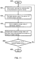
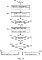
- the water-leakage detection processing in the step 303 performed by the water-leakage detection processing section 33 and the position localization processing in the step 305 performed by the position localization processing section 35 in the operation of the processing center section 30 are described in detail using FIGs. 11 and 12 .
- step 400 data to be processed of each acoustic sensor 10 is selected in order, and a power spectrum is derived in a step 401.
- step 402 plural points of past acoustic data of the acoustic sensor, with no detection of water-leakage, are read out from the signal accumulation section 32, and power spectra of them are derived.
- the power spectra are derived in the steps 401 and 402, calculation of Fourier transform is performed.
- each acoustic data may be subjected to Fourier transform not only one time but plural times, and the results may be integrated or averaged by frequency bin to absorb a fluctuation component in a short time.
- the derived past power spectra are subjected to time-series weighting, and an average value thereof is derived.
- the time-series weighting is, for example, a method in which an average is determined by setting a weighting coefficient for the latest data in terms of time to be high and setting a weighting coefficient for the data far away in terms of time to be low.
- an average value responding to a change in physical environmental condition in an area surrounding each acoustic sensor 10 can be derived.
- the past weighted average value and the latest value are compared, and the presence or absence of a water-leakage is determined from the presence or absence of a characteristic difference in spectrum between both of the values and the like.
- the determination by listening may be performed by an intervention of an investigator who performs the operation in the processing center section 30 as required.
- the presence or absence of a water-leakage may be determined using other acoustic analysis methods.
- the processing is ended (step 406), and when not finished (No), the operation returns to the step 401, and determinations of the other acoustic sensors are continued.
- step 501 time waveform data of acoustic sensors 10 as a pair are selected, the data are subjected to cross-correlation processing, and a difference between arrival times of water-leakage sounds is determined. Subsequently, a hyperbola with the acoustic sensors 10 as foci is derived from the product of the determined difference between arrival times and the sound velocity under the ground. In fact, it is difficult to accurately assume the sound velocity.
- a hyperbola in the case of the lower limit of the assumed sound velocity and a hyperbola in the case of the upper limit of the assumed sound velocity are determined, and a hyperbola-like region that is present between the hyperbolas is used as an area in which a water-leakage spot can be present.
- a step 502 an arrival direction of water-leakage sounds is found from a phase difference between waveforms of the water-leakage sounds subjected to cross-correlation processing in the step 501.
- either one of hyperbola-like regions which are drawn symmetrically on the midpoint between the two acoustic sensors 10 is specified.
- a step 503 whether or not all of pairs of acoustic sensors 10 detecting water-leakage sounds are subjected to cross-correlation processing is checked, and when finished (Yes), the operation goes to a step 504, and when not finished (No), the operation returns to the step 501 to continue the processing.
- plural hyperbola-like areas in which a water-leakage spot can be present are determined as described above, an actual water-leakage spot is, as shown in FIG. 4 , present in a part in which all of the plural hyperbola-like regions are overlapped with one another.
- a solution in which areas in which the plural hyperbolas-like regions intersect with one another converge into one is determined using the sound velocity as a variable. Specifically, for example, in the case where three regions intersect with one another as shown in FIG. 4 , when a value is determined as a sound velocity, three hyperbola-like regions converge into three hyperbolas, and the three hyperbolas intersect with one another at a total of three intersections.
- the sound velocity is changed in order at an appropriate step width, between the lower limit of the assumed sound velocity and the upper limit of the assumed sound velocity, the sum of geometric distances among three intersections at each sound velocity is determined, and a solution in which the sum is minimum, i.e., a solution in which the three intersections converge into one may be searched for.
- the method for determining a convergent solution is not limited to the above-described method, and any of the other methods may be used.
- a solution is searched for in the step 504, and in the step 505, when the result of the search shows that there is no convergent point (No), the processing is ended as a false detection such as a noise or the like (step 508).
- the operation goes to a step 506, and whether or not the convergent point is present on a conduit is determined on the basis of information in a sensor position DB section 34.
- the processing is ended as a water-leakage position is localized (step 507), and when the convergent point is not present on a conduit (No), the processing is ended as a false detection caused by a sound source other than a water-leakage (step 508).
- an intensity ratio of water-leakage sounds on both of power spectra is a function of a distance from a water-leakage spot.
- a convergent solution can be determined utilizing the function as a convergent condition.
- a mechanism of time synchronization between different acoustic sensors can be minimized. This is because a water-leakage position that is outside of an area of acoustic sensors can be localized by placing the acoustic sensors apart from a pipeline, so that a range in which a water-leakage can be searched for can be set in a wide range. In this case, it is only required that two acoustic sensors that are close to each other as a pair are subjected to time synchronization, and it is not necessary to subject all of acoustic sensors to time synchronization.
- the fifth embodiment of the present invention is described in detail below with reference to a figure.
- two acoustic sensors 10 as a pair are subjected to time synchronization immediately before the acquisition of acoustic data, and an accurate measurement of a difference between arrival times of water-leakage sounds is performed by cross-correlation processing. Therefore, the characteristics are that, by planarly arranging the pairs, a water-leakage position can be localized from the processing results of a plurality of the pairs even when the sound velocity under the ground is indefinite.
- a water-leakage position can be localized without another set of acoustic sensors even when the sound velocity under the ground is indefinite.
- three hyperbolas with the respective combinations of acoustic sensors as foci can be drawn.
- the spot becomes a water-leakage spot.
- the configuration of the fifth embodiment is the same as that of the fourth embodiment except that three acoustic sensors are used as a set as substitute for two acoustic sensors as a pair.
- the operation of the fifth embodiment is different from that of the fourth embodiment in a flow of a master-side acoustic sensor 1 and a flow in a position localization processing section 35.
- a time synchronization section 15 refers to an internal clock and check whether or not the time is the time to collect data, such as the quiet of the midnight or the like.
- a signal is sent to a first slave- (slave #1) side acoustic sensor via a ground-side wireless communication section 14 to activate, and a master-side acoustic sensor and the first slave-side acoustic sensor are subjected to relative time synchronization.
- a signal is sent to a second slave- (slave #2) side acoustic sensor to activate, and the master-side acoustic sensor and the second slave-side acoustic sensor are subjected to relative time synchronization.
- the time synchronization of the three acoustic sensors is finished as described above.
- the descriptions of a subsequent operation and an operation of each slave-side acoustic sensor are omitted because the operations are the same as those in the fourth embodiment.
- step 700 time waveform data of three combinations of the acoustic sensors as sets are selected, the three combinations of the data are subjected to cross-correlation processing, and each difference between arrival times of water-leakage sounds is determined. Subsequently, three hyperbola-like regions with the respective three combinations of the acoustic sensors as foci are derived from the products of the respective determined three differences between arrival times and the lower limit and the upper limit of the assumed sound velocity under the ground.
- a step 702 an arrival direction of water-leakage sounds is found from phase differences between three waveforms of the water-leakage sounds subjected to cross-correlation processing in the step 701.
- a solution in which areas in which the three hyperbola-like regions intersect with one another converge into one is determined using the sound velocity as a variable. The description of a subsequent operation is omitted because the operation is the same as that in the fourth embodiment.
- a water leakage position can be localized without planarly arranging acoustic sensors using and subjecting three acoustic sensors as a set to time synchronization and cross-correlation processing even when the sound velocity under the ground is indefinite.
- a leakage detection method, a water-leakage detection method, a leakage detection device, and a water-leakage detection device, for a pipe with an ease of placing sensors, high accuracy of detection, and high reliability can be provided.
- detection of water-leakage can be efficiently performed in a wide range of location.
- efficiency of searching for water-leakage is dramatically improved, and a problem of securing investigators with skilled technique is solved.
- a water-leakage from a conduit is specifically described.
- the object to which the present invention is applied is not limited to the conduit and can be leakages of various fluid from a gas pipe and a plant pipe.
Landscapes
- Physics & Mathematics (AREA)
- Engineering & Computer Science (AREA)
- Acoustics & Sound (AREA)
- Mechanical Engineering (AREA)
- General Engineering & Computer Science (AREA)
- General Physics & Mathematics (AREA)
- Examining Or Testing Airtightness (AREA)
Claims (12)
- Leckortungsverfahren zum Orten eines Lecks in einem Rohr (5), in dem ein Fluid fließt, unter Verwendung eines Paars akustischer Sensoren (1, 2, 3, 10), die in einem bestimmten Abstand voneinander und in einem bestimmten Abstand von einem Ort des Rohrs (5) angeordnet sind, wobei das Verfahren aufweist:einen Schritt zur Erfassung akustischer Daten zum Durchführen einer Zeitsynchronisation zwischen dem Paar akustischer Sensoren (1, 2, 3, 10) und zum Erfassen von akustischen Daten durch das Paar akustischer Sensoren (1, 2, 3, 10);ein Zeitdifferenz-Berechnungsschritt zum Bestimmen einer Differenz zwischen Ankunftszeiten von Tönen, die durch die jeweiligen akustischen Sensoren (1, 2, 3, 10) empfangen werden;ein Abstandsdifferenz-Berechnungsschritt zum Berechnen aus der Differenz zwischen Ankunftszeiten einer Differenz zwischen Abständen von einer Quelle der Töne zu den jeweiligen akustischen Sensoren (1, 2, 3, 10);einen Schritt zur Erfassung einer Hyperbel (6, 7, 8) zum Bestimmen einer Hyperbel (6, 7, 8), die die Positionen der jeweiligen akustischen Sensoren (1, 2, 3, 10) als Brennpunkte aufweist, wobei eine Abstandsdifferenz von jedem der akustischen Sensoren (1, 2, 3, 10) konstant ist; undein Positionsermittlungsschritt zum Ermitteln einer Position (x) des Lecks aus einem Schnittpunkt zwischen dem Rohr (5) und der Hyperbel (6, 7, 8).
- Leckortungsverfahren nach Anspruch 1, wobei
eine Vielzahl der Paare akustischer Sensoren (1, 2, 3, 10) verwendet wird,
im Hyperbelerfassungsschritt Hyperbeln (6, 7, 8) für die jeweiligen Paare bestimmt werden, und
im Positionsermittlungsschritt Schnittpunkte der für die jeweiligen Paare bestimmten Hyperbeln (6, 7, 8) einer gewichteten Mittelwertbildung unterzogen werden, um eine Position der Quelle der Töne zu ermitteln. - Leckortungsverfahren nach Anspruch 1 oder 2, wobei
mindestens drei akustische Sensoren (1, 2, 3, 10) als ein Satz als Ersatz für die beiden akustischen Sensoren (1, 2, 3, 10) verwendet werden, und
im Hyperbelerfassungsschritt mindestens drei Arten von Hyperbeln (6, 7, 8) bestimmt werden, wobei als Brennpunkte Kombinationen von zwei akustischen Sensoren (1, 2, 3, 10) aus den mindestens drei akustischen Sensoren (1, 2, 3, 10) verwendet werden. - Leckortungsverfahren nach einem der Ansprüche 1 bis 3, wobei
mindestens drei Paare akustischer Sensoren (1, 2, 3, 10) verwendet werden, und
im Positionsermittlungsschritt die Schnittpunkte unter Verwendung einer Schallgeschwindigkeit in einem Medium als einen variablen Parameter bestimmt werden, in dem sich der Schall ausbreitet. - Leckortungsverfahren nach einem der Ansprüche 1 bis 4, das vor dem Zeitdifferenz-Berechnungsschritt aufweist:einen Bestimmungsschritt zum Ableiten eines Leistungsspektrums von akustischen Daten, die durch den akustischen Sensor (1, 2, 3, 10) empfangen werden, und zum Vergleichen des Leistungsspektrums mit einem Leistungsspektrum von vergangenen akustischen Daten ohne eine Erkennung eines Lecks, um das Vorhandensein oder Fehlen eines Lecks zu bestimmen.
- Leckortungsverfahren nach Anspruch 5, wobei wenn mehrere Schnittpunkte der Hyperbeln (6, 7, 8) vorhanden sind, im Positionsermittlungsschritt eine Position des Lecks unter Verwendung von Intensitätsverhältnisdaten von Lecktönen auf dem Leistungsspektrum der akustischen Daten ermittelt wird, die durch die akustischen Sensoren (1, 2, 3, 10) empfangen werden.
- Leckortungsvorrichtung zum Orten eines Lecks in einem Rohr (5), in dem ein Fluid fließt, wobei die Leckortungsvorrichtung aufweist:eine Einheit zur Erfassung akustischer Daten, die aus einem Paar akustischer Sensoren (1, 2, 3, 10) besteht, die zum Erfassen akustischer Daten imstande sind und einer Zeitsynchronisation unterzogen werden, die in einem bestimmten Abstand voneinander und in einem bestimmten Abstand von einem Ort des Rohrs (5) angeordnet sind;eine Zeitdifferenz-Berechnungseinheit, die konfiguriert ist, eine Differenz zwischen Ankunftszeiten von Tönen zu bestimmen, die durch die jeweiligen akustischen Sensoren (1, 2, 3, 10) empfangen werden;eine Abstandsdifferenz-Berechnungseinheit, die konfiguriert ist, aus der Differenz zwischen Ankunftszeiten eine Differenz zwischen Abständen von einer Quelle der Töne zu den jeweiligen akustischen Sensoren (1, 2, 3, 10) zu berechnen;eine Hyperbelerfassungseinheit, die konfiguriert ist, eine Hyperbel (6, 7, 8) zu bestimmen, die die Positionen der jeweiligen akustischen Sensoren (1, 2, 3, 10) als Brennpunkte aufweist, wobei eine Abstandsdifferenz von jedem der akustischen Sensoren (1, 2, 3, 10) konstant ist; undeine Positionsermittlungseinheit, die konfiguriert ist, eine Position (x) des Lecks aus einem Schnittpunkt zwischen dem Rohr (5) und der Hyperbel (6, 7, 8) zu ermitteln.
- Leckortungsvorrichtung nach Anspruch 7, wobei eine Vielzahl der Paare der akustischer Sensoren (1, 2, 3, 10) verwendet wird,
die Hyperbelerfassungseinheit konfiguriert ist, Hyperbeln (6, 7, 8) für die jeweiligen Paare zu bestimmen, und
die Positionsermittlungseinheit konfiguriert ist, Schnittpunkte der für die jeweiligen Paare bestimmten Hyperbeln (6, 7, 8) einer gewichteten Mittelwertbildung zu unterziehen, um eine Position der Quelle der Töne zu ermitteln. - Leckortungsvorrichtung nach Anspruch 7 oder 8, wobei
mindestens drei akustische Sensoren (1, 2, 3, 10) als ein Satz als Ersatz für die beiden akustischen Sensoren (1, 2, 3, 10) verwendet werden, und
die Hyperbelerfassungseinheit konfiguriert ist, mindestens drei Arten von Hyperbeln (6, 7, 8) zu bestimmen, wobei als Brennpunkte Kombinationen von zwei akustischen Sensoren (1, 2, 3, 10) aus den mindestens drei akustischen Sensoren (1, 2, 3, 10) verwendet werden. - Leckortungsvorrichtung nach einem der Ansprüche 7 bis 9, wobei
mindestens drei Paare akustischer Sensoren (1, 2, 3, 10) verwendet werden, und
die Positionsermittlungseinheit konfiguriert ist, die Schnittpunkte unter Verwendung einer Schallgeschwindigkeit als einen variablen Parameter in einem Medium zu bestimmen, in dem sich der Schall ausbreitet. - Leckortungsvorrichtung nach einem der Ansprüche 7 bis 10, die ferner aufweist:eine Bestimmungseinheit, die konfiguriert ist, ein Leistungsspektrum von akustischen Daten abzuleiten, die durch die akustischen Sensoren (1, 2, 3, 10) empfangen werden, und es mit einem Leistungsspektrum von vergangenen akustischen Daten ohne eine Erkennung eines Lecks zu vergleichen, um das Vorhandensein oder Fehlen eines Lecks zu bestimmen.
- Leckortungsvorrichtung nach Anspruch 11, wobei wenn mehrere Schnittpunkte der Hyperbeln (6, 7, 8) vorhanden sind, die Positionsermittlungseinheit eine Position des Lecks unter Verwendung von Intensitätsverhältnisdaten von Lecktönen auf dem Leistungsspektrum der akustischen Daten ermittelt, die durch die akustischen Sensoren (1, 2, 3, 10) empfangen werden.
Applications Claiming Priority (2)
| Application Number | Priority Date | Filing Date | Title |
|---|---|---|---|
| JP2012082165A JP5846015B2 (ja) | 2012-03-30 | 2012-03-30 | 漏洩検知方法、漏水検知方法、漏洩検知装置および漏水検知装置 |
| PCT/JP2012/084046 WO2013145492A1 (ja) | 2012-03-30 | 2012-12-28 | 漏洩検知方法、漏水検知方法、漏洩検知装置および漏水検知装置 |
Publications (3)
| Publication Number | Publication Date |
|---|---|
| EP2833113A1 EP2833113A1 (de) | 2015-02-04 |
| EP2833113A4 EP2833113A4 (de) | 2015-11-11 |
| EP2833113B1 true EP2833113B1 (de) | 2017-05-03 |
Family
ID=49258821
Family Applications (1)
| Application Number | Title | Priority Date | Filing Date |
|---|---|---|---|
| EP12873033.0A Active EP2833113B1 (de) | 2012-03-30 | 2012-12-28 | Leckagenerkennungsverfahren, verfahren zur erkennung von wasserleckagen, leckagenerkennungsvorrichtung sowie vorrichtung zur erkennung von wasserleckagen |
Country Status (3)
| Country | Link |
|---|---|
| EP (1) | EP2833113B1 (de) |
| JP (1) | JP5846015B2 (de) |
| WO (1) | WO2013145492A1 (de) |
Families Citing this family (35)
| Publication number | Priority date | Publication date | Assignee | Title |
|---|---|---|---|---|
| DE102011122547A1 (de) * | 2011-12-28 | 2013-07-04 | Seba-Dynatronic Mess- Und Ortungstechnik Gmbh | Verfahren und Vorrichtung zur Lokalisation von Datenloggern an Versorgungsleitungen mit einem Auslesegerät |
| JP6436164B2 (ja) * | 2014-03-28 | 2018-12-12 | 日本電気株式会社 | 時刻参照端末、計測端末、時刻同期システムおよび時刻同期方法 |
| JP6370596B2 (ja) * | 2014-04-28 | 2018-08-08 | 株式会社東芝 | 漏水監視システム、漏水監視方法、漏水監視装置、および漏水監視プログラム |
| KR101454288B1 (ko) * | 2014-05-02 | 2014-10-27 | 에스케이건설 주식회사 | 누수 탐지 시스템 |
| CN104132248B (zh) * | 2014-07-31 | 2016-10-19 | 重庆大学 | 流体管道泄漏检测定位方法 |
| CN104359008B (zh) * | 2014-11-25 | 2017-04-05 | 天津市林海建设工程集团有限公司 | 管网音频采集器及实现方法 |
| CN105042341B (zh) * | 2015-07-31 | 2017-06-30 | 中国石油大学(华东) | 基于声发射检测的埋地管道泄漏源多层次定位装置及方法 |
| CN106090630B (zh) * | 2016-06-16 | 2018-07-31 | 厦门数析信息科技有限公司 | 基于集成分类器的液体管道检漏方法及其系统 |
| CN106595983A (zh) * | 2016-12-07 | 2017-04-26 | 怀宁县鑫泰钢结构有限公司 | 铸铁管生产标记检测系统 |
| CN107061998A (zh) * | 2017-03-28 | 2017-08-18 | 上海工程技术大学 | 墙体内水管漏水检测装置及检测处理系统 |
| JP6840066B2 (ja) * | 2017-11-22 | 2021-03-10 | 株式会社日立製作所 | 漏水検知システムおよび漏水検知方法 |
| JP6903022B2 (ja) * | 2018-02-06 | 2021-07-14 | 三菱電機株式会社 | 水運用保守統合システム |
| CN109340585B (zh) * | 2018-10-26 | 2020-10-27 | 北京化工大学 | 一种管道泄漏检测及定位方法 |
| TWI683104B (zh) * | 2018-12-28 | 2020-01-21 | 財團法人工業技術研究院 | 偵測系統及偵測方法 |
| US11525811B2 (en) | 2018-12-28 | 2022-12-13 | Industrial Technology Research Institute | Detection system and detection method |
| CN109915739B (zh) * | 2019-04-11 | 2021-01-05 | 中国石油化工股份有限公司 | 一种基于喷注噪声的海底管道泄漏检测系统 |
| CN114026620B (zh) * | 2019-05-09 | 2024-06-25 | 日本富士(地探)株式会社 | 数据收集装置、信号产生位置确定系统、数据收集方法、信号产生位置确定方法以及程序 |
| CN112432061A (zh) * | 2019-08-26 | 2021-03-02 | 苏州安能通智能科技有限公司 | 一种管道泄漏监测方法及系统 |
| JP7250281B2 (ja) * | 2019-12-12 | 2023-04-03 | 本田技研工業株式会社 | 三次元構造復元装置、三次元構造復元方法、およびプログラム |
| CN111720753A (zh) * | 2020-04-09 | 2020-09-29 | 苏州市自来水有限公司 | 一种基于噪声监测技术的小区dma探漏管控方法 |
| CN112857699B (zh) * | 2021-01-03 | 2023-09-29 | 西安金时利和自动化工程有限公司 | 一种声矢量传感器的长输油气管道泄漏检测和定位方法 |
| CN112923245B (zh) * | 2021-02-03 | 2024-02-13 | 宁波水表(集团)股份有限公司 | 一种供水管网漏损探查的方法 |
| CN113324645B (zh) * | 2021-04-14 | 2024-08-02 | 华翔翔能科技股份有限公司 | 一种智慧楼宇供水管理方法及系统 |
| CN113719761B (zh) * | 2021-08-16 | 2022-06-10 | 杭州斯塔克智慧水务有限公司 | 一种实现城市水管网漏损的检测分析装置 |
| CN113653952A (zh) * | 2021-08-17 | 2021-11-16 | 北京首创生态环保集团股份有限公司 | 一种基于物联网的供水管网泄露监测装置及系统 |
| KR102407676B1 (ko) * | 2022-02-17 | 2022-06-10 | 주식회사 위플랫 | 동수두 분석에 근거한 누수 탐지 시스템 및 방법 |
| CN114894393B (zh) * | 2022-03-28 | 2024-05-03 | 上海化工研究院有限公司 | 一种便携式高压氢气泄漏超声波检测仪 |
| CN115793035B (zh) * | 2022-11-11 | 2023-06-30 | 北京信息科技大学 | 一种基于声波主动激励的地下非金属管线探测系统及方法 |
| CN116660826B (zh) * | 2023-05-17 | 2023-12-19 | 中天射频电缆有限公司 | 泄漏装置、定位方法及电子设备 |
| CN116857572B (zh) * | 2023-07-14 | 2024-01-02 | 湖南理工学院 | 一种基于大数据的智慧水务管理方法及系统 |
| KR102691546B1 (ko) * | 2024-01-12 | 2024-08-05 | 주식회사 유솔 | 도로표시못을 이용한 배관 데이터 통신 시스템 |
| KR102710781B1 (ko) * | 2024-01-12 | 2024-09-27 | 주식회사 유솔 | 지하매설물의 배관 데이터 통신 시스템 |
| CN117927883A (zh) * | 2024-03-21 | 2024-04-26 | 成都天传科技有限公司 | 一种水利工程管道的漏点无源无线定位方法及系统 |
| CN119123221B (zh) * | 2024-09-25 | 2025-12-05 | 中国长江电力股份有限公司 | 一种防止泄漏液体蔓延的快速封堵装置及方法 |
| CN119845504A (zh) * | 2025-01-08 | 2025-04-18 | 青岛哈尔滨工程大学创新发展中心 | 一种基于深度学习的水下渗漏声音识别方法和系统 |
Family Cites Families (13)
| Publication number | Priority date | Publication date | Assignee | Title |
|---|---|---|---|---|
| JPH0238937A (ja) * | 1988-07-29 | 1990-02-08 | Toshiba Corp | 圧力容器リーク検出装置 |
| JPH03279833A (ja) * | 1990-03-28 | 1991-12-11 | Toshiba Corp | チューブリーク検知装置 |
| JP2804687B2 (ja) * | 1992-10-13 | 1998-09-30 | 鹿島建設株式会社 | 池の漏水位置検知方法 |
| JPH07248274A (ja) * | 1994-03-09 | 1995-09-26 | Babcock Hitachi Kk | チューブリーク位置検出装置 |
| US5533383A (en) * | 1994-08-18 | 1996-07-09 | General Electric Company | Integrated acoustic leak detection processing system |
| JPH10176970A (ja) * | 1996-12-16 | 1998-06-30 | Res:Kk | 漏洩箇所検出装置 |
| JPH1172409A (ja) | 1997-06-23 | 1999-03-16 | Mitsui Eng & Shipbuild Co Ltd | 配管の漏洩検知方法 |
| JP3718740B2 (ja) | 1997-10-13 | 2005-11-24 | 作治 藏田 | 配水管の漏水検知方法及び漏水検知システム |
| JP3488623B2 (ja) | 1998-03-04 | 2004-01-19 | 東京都 | 漏水位置検出方法および漏水位置検出装置 |
| DE10315987A1 (de) * | 2003-04-07 | 2004-10-28 | Riehle, Rainer, Dipl.-Ing. | Einrichtung zur Erkennung und näherungsweisen Ortung eines Lecks in einem Trinkwasserversorgungsnetz |
| US7739899B1 (en) * | 2005-04-29 | 2010-06-22 | Iowa State University Research Foundation, Inc. | Leak detection using structure-borne noise |
| JP4745170B2 (ja) | 2006-08-28 | 2011-08-10 | 株式会社東芝 | 漏水検出装置および漏水検出方法 |
| EP2352002B1 (de) * | 2010-01-29 | 2013-10-30 | Politecnico Di Torino | System zur entfernten Leckdetektion und/oder Pfadverfolgung für unterirdische Rohrleitungen zum Flüssigkeitstransport |
-
2012
- 2012-03-30 JP JP2012082165A patent/JP5846015B2/ja active Active
- 2012-12-28 WO PCT/JP2012/084046 patent/WO2013145492A1/ja not_active Ceased
- 2012-12-28 EP EP12873033.0A patent/EP2833113B1/de active Active
Also Published As
| Publication number | Publication date |
|---|---|
| WO2013145492A1 (ja) | 2013-10-03 |
| EP2833113A1 (de) | 2015-02-04 |
| JP2013210347A (ja) | 2013-10-10 |
| JP5846015B2 (ja) | 2016-01-20 |
| EP2833113A4 (de) | 2015-11-11 |
Similar Documents
| Publication | Publication Date | Title |
|---|---|---|
| EP2833113B1 (de) | Leckagenerkennungsverfahren, verfahren zur erkennung von wasserleckagen, leckagenerkennungsvorrichtung sowie vorrichtung zur erkennung von wasserleckagen | |
| KR101876730B1 (ko) | 상수도 누수탐지 감시 시스템 | |
| US9939344B2 (en) | Detecting leaks in a fluid distribution system | |
| US9766151B2 (en) | Leakage analysis system and leakage detection method using at least two measurement terminals | |
| US9909949B2 (en) | Leakage determination method, leakage determination system, and program | |
| US10132823B2 (en) | Method and system for the continuous remote tracking of a pig device and detection of anomalies inside a pressurized pipeline | |
| KR101555461B1 (ko) | 상수관망 누수탐지 방법 | |
| KR101454288B1 (ko) | 누수 탐지 시스템 | |
| CN101832472A (zh) | 利用次声波实现管道泄漏检测的系统 | |
| JP7646885B2 (ja) | 分散型光ファイバセンシングを用いた、配備されたファイバケーブルの位置決定 | |
| Van Hieu et al. | Wireless transmission of acoustic emission signals for real-time monitoring of leakage in underground pipes | |
| US10078069B2 (en) | Device for detecting change in underground medium | |
| KR101956160B1 (ko) | 누수 탐지 장치 | |
| US20240035630A1 (en) | Method And System Of Leak Detection | |
| JP2017187337A (ja) | 漏水調査方法 | |
| US10119880B2 (en) | Leakage position calculation device, leakage position calculation method, computer-readable recording medium, vibration calculation device, and computation device | |
| JP6789042B2 (ja) | 漏水場所の特定方法 | |
| CN120820809A (zh) | 一种基于水下信标的海底电缆故障定位系统 | |
| CN210141480U (zh) | 一种天然气管网泄漏监测系统 | |
| CN112432061A (zh) | 一种管道泄漏监测方法及系统 | |
| CN116624790A (zh) | 基于融合广义互相关的供水管网泄漏精确定位方法 | |
| EP4071454B1 (de) | Verfahren zur ortung eines lecks in einem wasserversorgungsnetz | |
| JP2005265701A (ja) | 異常箇所検出装置 | |
| CN120947489A (zh) | 一种面向三维复杂结构的分布式光纤振动定位系统及方法 | |
| AU2023302871A1 (en) | Sensor synchronisation suited for a leak detection system |
Legal Events
| Date | Code | Title | Description |
|---|---|---|---|
| PUAI | Public reference made under article 153(3) epc to a published international application that has entered the european phase |
Free format text: ORIGINAL CODE: 0009012 |
|
| 17P | Request for examination filed |
Effective date: 20140903 |
|
| AK | Designated contracting states |
Kind code of ref document: A1 Designated state(s): AL AT BE BG CH CY CZ DE DK EE ES FI FR GB GR HR HU IE IS IT LI LT LU LV MC MK MT NL NO PL PT RO RS SE SI SK SM TR |
|
| AX | Request for extension of the european patent |
Extension state: BA ME |
|
| DAX | Request for extension of the european patent (deleted) | ||
| RA4 | Supplementary search report drawn up and despatched (corrected) |
Effective date: 20151012 |
|
| RIC1 | Information provided on ipc code assigned before grant |
Ipc: F17D 5/06 20060101ALI20151006BHEP Ipc: G01M 3/24 20060101AFI20151006BHEP |
|
| GRAP | Despatch of communication of intention to grant a patent |
Free format text: ORIGINAL CODE: EPIDOSNIGR1 |
|
| INTG | Intention to grant announced |
Effective date: 20161115 |
|
| GRAS | Grant fee paid |
Free format text: ORIGINAL CODE: EPIDOSNIGR3 |
|
| GRAA | (expected) grant |
Free format text: ORIGINAL CODE: 0009210 |
|
| RIN1 | Information on inventor provided before grant (corrected) |
Inventor name: TANAKA, TOSHIAKI |
|
| AK | Designated contracting states |
Kind code of ref document: B1 Designated state(s): AL AT BE BG CH CY CZ DE DK EE ES FI FR GB GR HR HU IE IS IT LI LT LU LV MC MK MT NL NO PL PT RO RS SE SI SK SM TR |
|
| REG | Reference to a national code |
Ref country code: GB Ref legal event code: FG4D |
|
| REG | Reference to a national code |
Ref country code: AT Ref legal event code: REF Ref document number: 890507 Country of ref document: AT Kind code of ref document: T Effective date: 20170515 Ref country code: CH Ref legal event code: EP |
|
| REG | Reference to a national code |
Ref country code: IE Ref legal event code: FG4D |
|
| REG | Reference to a national code |
Ref country code: DE Ref legal event code: R096 Ref document number: 602012032117 Country of ref document: DE |
|
| REG | Reference to a national code |
Ref country code: NL Ref legal event code: MP Effective date: 20170503 |
|
| REG | Reference to a national code |
Ref country code: AT Ref legal event code: MK05 Ref document number: 890507 Country of ref document: AT Kind code of ref document: T Effective date: 20170503 |
|
| REG | Reference to a national code |
Ref country code: LT Ref legal event code: MG4D |
|
| PG25 | Lapsed in a contracting state [announced via postgrant information from national office to epo] |
Ref country code: NO Free format text: LAPSE BECAUSE OF FAILURE TO SUBMIT A TRANSLATION OF THE DESCRIPTION OR TO PAY THE FEE WITHIN THE PRESCRIBED TIME-LIMIT Effective date: 20170803 Ref country code: FI Free format text: LAPSE BECAUSE OF FAILURE TO SUBMIT A TRANSLATION OF THE DESCRIPTION OR TO PAY THE FEE WITHIN THE PRESCRIBED TIME-LIMIT Effective date: 20170503 Ref country code: ES Free format text: LAPSE BECAUSE OF FAILURE TO SUBMIT A TRANSLATION OF THE DESCRIPTION OR TO PAY THE FEE WITHIN THE PRESCRIBED TIME-LIMIT Effective date: 20170503 Ref country code: LT Free format text: LAPSE BECAUSE OF FAILURE TO SUBMIT A TRANSLATION OF THE DESCRIPTION OR TO PAY THE FEE WITHIN THE PRESCRIBED TIME-LIMIT Effective date: 20170503 Ref country code: AT Free format text: LAPSE BECAUSE OF FAILURE TO SUBMIT A TRANSLATION OF THE DESCRIPTION OR TO PAY THE FEE WITHIN THE PRESCRIBED TIME-LIMIT Effective date: 20170503 Ref country code: HR Free format text: LAPSE BECAUSE OF FAILURE TO SUBMIT A TRANSLATION OF THE DESCRIPTION OR TO PAY THE FEE WITHIN THE PRESCRIBED TIME-LIMIT Effective date: 20170503 Ref country code: GR Free format text: LAPSE BECAUSE OF FAILURE TO SUBMIT A TRANSLATION OF THE DESCRIPTION OR TO PAY THE FEE WITHIN THE PRESCRIBED TIME-LIMIT Effective date: 20170804 |
|
| PG25 | Lapsed in a contracting state [announced via postgrant information from national office to epo] |
Ref country code: PL Free format text: LAPSE BECAUSE OF FAILURE TO SUBMIT A TRANSLATION OF THE DESCRIPTION OR TO PAY THE FEE WITHIN THE PRESCRIBED TIME-LIMIT Effective date: 20170503 Ref country code: RS Free format text: LAPSE BECAUSE OF FAILURE TO SUBMIT A TRANSLATION OF THE DESCRIPTION OR TO PAY THE FEE WITHIN THE PRESCRIBED TIME-LIMIT Effective date: 20170503 Ref country code: BG Free format text: LAPSE BECAUSE OF FAILURE TO SUBMIT A TRANSLATION OF THE DESCRIPTION OR TO PAY THE FEE WITHIN THE PRESCRIBED TIME-LIMIT Effective date: 20170803 Ref country code: SE Free format text: LAPSE BECAUSE OF FAILURE TO SUBMIT A TRANSLATION OF THE DESCRIPTION OR TO PAY THE FEE WITHIN THE PRESCRIBED TIME-LIMIT Effective date: 20170503 Ref country code: IS Free format text: LAPSE BECAUSE OF FAILURE TO SUBMIT A TRANSLATION OF THE DESCRIPTION OR TO PAY THE FEE WITHIN THE PRESCRIBED TIME-LIMIT Effective date: 20170903 Ref country code: NL Free format text: LAPSE BECAUSE OF FAILURE TO SUBMIT A TRANSLATION OF THE DESCRIPTION OR TO PAY THE FEE WITHIN THE PRESCRIBED TIME-LIMIT Effective date: 20170503 Ref country code: LV Free format text: LAPSE BECAUSE OF FAILURE TO SUBMIT A TRANSLATION OF THE DESCRIPTION OR TO PAY THE FEE WITHIN THE PRESCRIBED TIME-LIMIT Effective date: 20170503 |
|
| PG25 | Lapsed in a contracting state [announced via postgrant information from national office to epo] |
Ref country code: SK Free format text: LAPSE BECAUSE OF FAILURE TO SUBMIT A TRANSLATION OF THE DESCRIPTION OR TO PAY THE FEE WITHIN THE PRESCRIBED TIME-LIMIT Effective date: 20170503 Ref country code: RO Free format text: LAPSE BECAUSE OF FAILURE TO SUBMIT A TRANSLATION OF THE DESCRIPTION OR TO PAY THE FEE WITHIN THE PRESCRIBED TIME-LIMIT Effective date: 20170503 Ref country code: CZ Free format text: LAPSE BECAUSE OF FAILURE TO SUBMIT A TRANSLATION OF THE DESCRIPTION OR TO PAY THE FEE WITHIN THE PRESCRIBED TIME-LIMIT Effective date: 20170503 Ref country code: DK Free format text: LAPSE BECAUSE OF FAILURE TO SUBMIT A TRANSLATION OF THE DESCRIPTION OR TO PAY THE FEE WITHIN THE PRESCRIBED TIME-LIMIT Effective date: 20170503 Ref country code: EE Free format text: LAPSE BECAUSE OF FAILURE TO SUBMIT A TRANSLATION OF THE DESCRIPTION OR TO PAY THE FEE WITHIN THE PRESCRIBED TIME-LIMIT Effective date: 20170503 |
|
| REG | Reference to a national code |
Ref country code: DE Ref legal event code: R097 Ref document number: 602012032117 Country of ref document: DE |
|
| PG25 | Lapsed in a contracting state [announced via postgrant information from national office to epo] |
Ref country code: IT Free format text: LAPSE BECAUSE OF FAILURE TO SUBMIT A TRANSLATION OF THE DESCRIPTION OR TO PAY THE FEE WITHIN THE PRESCRIBED TIME-LIMIT Effective date: 20170503 Ref country code: SM Free format text: LAPSE BECAUSE OF FAILURE TO SUBMIT A TRANSLATION OF THE DESCRIPTION OR TO PAY THE FEE WITHIN THE PRESCRIBED TIME-LIMIT Effective date: 20170503 |
|
| PLBE | No opposition filed within time limit |
Free format text: ORIGINAL CODE: 0009261 |
|
| STAA | Information on the status of an ep patent application or granted ep patent |
Free format text: STATUS: NO OPPOSITION FILED WITHIN TIME LIMIT |
|
| 26N | No opposition filed |
Effective date: 20180206 |
|
| PG25 | Lapsed in a contracting state [announced via postgrant information from national office to epo] |
Ref country code: SI Free format text: LAPSE BECAUSE OF FAILURE TO SUBMIT A TRANSLATION OF THE DESCRIPTION OR TO PAY THE FEE WITHIN THE PRESCRIBED TIME-LIMIT Effective date: 20170503 |
|
| REG | Reference to a national code |
Ref country code: DE Ref legal event code: R119 Ref document number: 602012032117 Country of ref document: DE |
|
| REG | Reference to a national code |
Ref country code: CH Ref legal event code: PL |
|
| REG | Reference to a national code |
Ref country code: IE Ref legal event code: MM4A |
|
| PG25 | Lapsed in a contracting state [announced via postgrant information from national office to epo] |
Ref country code: MT Free format text: LAPSE BECAUSE OF NON-PAYMENT OF DUE FEES Effective date: 20171228 Ref country code: LU Free format text: LAPSE BECAUSE OF NON-PAYMENT OF DUE FEES Effective date: 20171228 |
|
| REG | Reference to a national code |
Ref country code: FR Ref legal event code: ST Effective date: 20180831 |
|
| REG | Reference to a national code |
Ref country code: BE Ref legal event code: MM Effective date: 20171231 |
|
| PG25 | Lapsed in a contracting state [announced via postgrant information from national office to epo] |
Ref country code: DE Free format text: LAPSE BECAUSE OF NON-PAYMENT OF DUE FEES Effective date: 20180703 Ref country code: FR Free format text: LAPSE BECAUSE OF NON-PAYMENT OF DUE FEES Effective date: 20180102 Ref country code: IE Free format text: LAPSE BECAUSE OF NON-PAYMENT OF DUE FEES Effective date: 20171228 |
|
| PG25 | Lapsed in a contracting state [announced via postgrant information from national office to epo] |
Ref country code: BE Free format text: LAPSE BECAUSE OF NON-PAYMENT OF DUE FEES Effective date: 20171231 Ref country code: LI Free format text: LAPSE BECAUSE OF NON-PAYMENT OF DUE FEES Effective date: 20171231 Ref country code: CH Free format text: LAPSE BECAUSE OF NON-PAYMENT OF DUE FEES Effective date: 20171231 |
|
| PG25 | Lapsed in a contracting state [announced via postgrant information from national office to epo] |
Ref country code: MC Free format text: LAPSE BECAUSE OF FAILURE TO SUBMIT A TRANSLATION OF THE DESCRIPTION OR TO PAY THE FEE WITHIN THE PRESCRIBED TIME-LIMIT Effective date: 20170503 Ref country code: HU Free format text: LAPSE BECAUSE OF FAILURE TO SUBMIT A TRANSLATION OF THE DESCRIPTION OR TO PAY THE FEE WITHIN THE PRESCRIBED TIME-LIMIT; INVALID AB INITIO Effective date: 20121228 |
|
| PG25 | Lapsed in a contracting state [announced via postgrant information from national office to epo] |
Ref country code: CY Free format text: LAPSE BECAUSE OF FAILURE TO SUBMIT A TRANSLATION OF THE DESCRIPTION OR TO PAY THE FEE WITHIN THE PRESCRIBED TIME-LIMIT Effective date: 20170503 |
|
| PG25 | Lapsed in a contracting state [announced via postgrant information from national office to epo] |
Ref country code: MK Free format text: LAPSE BECAUSE OF FAILURE TO SUBMIT A TRANSLATION OF THE DESCRIPTION OR TO PAY THE FEE WITHIN THE PRESCRIBED TIME-LIMIT Effective date: 20170503 |
|
| PG25 | Lapsed in a contracting state [announced via postgrant information from national office to epo] |
Ref country code: TR Free format text: LAPSE BECAUSE OF FAILURE TO SUBMIT A TRANSLATION OF THE DESCRIPTION OR TO PAY THE FEE WITHIN THE PRESCRIBED TIME-LIMIT Effective date: 20170503 |
|
| PG25 | Lapsed in a contracting state [announced via postgrant information from national office to epo] |
Ref country code: PT Free format text: LAPSE BECAUSE OF FAILURE TO SUBMIT A TRANSLATION OF THE DESCRIPTION OR TO PAY THE FEE WITHIN THE PRESCRIBED TIME-LIMIT Effective date: 20170503 |
|
| PG25 | Lapsed in a contracting state [announced via postgrant information from national office to epo] |
Ref country code: AL Free format text: LAPSE BECAUSE OF FAILURE TO SUBMIT A TRANSLATION OF THE DESCRIPTION OR TO PAY THE FEE WITHIN THE PRESCRIBED TIME-LIMIT Effective date: 20170503 |
|
| PGFP | Annual fee paid to national office [announced via postgrant information from national office to epo] |
Ref country code: GB Payment date: 20251219 Year of fee payment: 14 |