EP2833154B1 - Spannungssensorvorrichtung - Google Patents
Spannungssensorvorrichtung Download PDFInfo
- Publication number
- EP2833154B1 EP2833154B1 EP13003868.0A EP13003868A EP2833154B1 EP 2833154 B1 EP2833154 B1 EP 2833154B1 EP 13003868 A EP13003868 A EP 13003868A EP 2833154 B1 EP2833154 B1 EP 2833154B1
- Authority
- EP
- European Patent Office
- Prior art keywords
- segment
- impedance
- elements
- segments
- connection system
- Prior art date
- Legal status (The legal status is an assumption and is not a legal conclusion. Google has not performed a legal analysis and makes no representation as to the accuracy of the status listed.)
- Active
Links
Images


Classifications
-
- G—PHYSICS
- G01—MEASURING; TESTING
- G01R—MEASURING ELECTRIC VARIABLES; MEASURING MAGNETIC VARIABLES
- G01R15/00—Details of measuring arrangements of the types provided for in groups G01R17/00 - G01R29/00, G01R33/00 - G01R33/26 or G01R35/00
- G01R15/04—Voltage dividers
- G01R15/06—Voltage dividers having reactive components, e.g. capacitive transformer
-
- G—PHYSICS
- G01—MEASURING; TESTING
- G01R—MEASURING ELECTRIC VARIABLES; MEASURING MAGNETIC VARIABLES
- G01R15/00—Details of measuring arrangements of the types provided for in groups G01R17/00 - G01R29/00, G01R33/00 - G01R33/26 or G01R35/00
- G01R15/04—Voltage dividers
-
- G—PHYSICS
- G01—MEASURING; TESTING
- G01R—MEASURING ELECTRIC VARIABLES; MEASURING MAGNETIC VARIABLES
- G01R27/00—Arrangements for measuring resistance, reactance, impedance, or electric characteristics derived therefrom
- G01R27/02—Measuring real or complex resistance, reactance, impedance, or other two-pole characteristics derived therefrom, e.g. time constant
Definitions
- the invention relates to a voltage sensor device, with at least one high voltage segment, and at least one low voltage impedance element.
- Known voltage divider for voltage sensor devices have sensing elements based on voltage divider, which generally consist of the high voltage impedance, e.g. a resistor part and a low voltage impedance part. According to the required application parameters, that means voltage and ratio, the sensing element can be bulky and thus not fitting the insulating sensor body available.
- the group of elements is supported by a dielectric the shape of which is such that it allows the creepage distance of the divider to be equal to or longer than the sum of creepage distances of the individual resistances. This arrangement allows a correct insulation of the device because it maintains the outer insulation since in the event of short-circuit the current will flow through the resistances and not through the support.
- the sensing element is adaptive and/or extendable in that way, that at least one high voltage segment, and at least one low voltage impedance element are arranged on an elongated insulating support (30) with adaptive complementary mechanical and electrical interconnection elements (71-79) at least one end of the support element, in order to interconnect at least two such support elements together in a pivotable way.
- the sensor device can be dimensionally adapted by the aforesaid adaptive mechanical and electrical interconnection system and/or pivoted by an angle among the segments or supports.
- the resulting value of impedance of the impedance elements can be built up together from standard impedance elements values.
- the impedance elements are either capacitive elements or a combination of resistive elements and capacitive elements.
- the impedance elements are connected within given segment in parallel and/or in series, providing required impedance value.
- the elements are assembled into at least partly fixed configuration with at least partly given dimensions and at least partly fixed angle between elements, having main fixed insulating support consisting of several elements and/or further possible connection to other separate elements.
- a last advantageous embodiment is, that the fixed insulating support has a possibility to mechanically reduce the number of elements by breaking or cutting off the unused part of said support.
- the said voltage sensing element generally consists of high voltage part and low voltage part, corresponding to Fig. 1 .
- the high voltage part consists of at least one segment 10. Such segment is further called high voltage segment.
- the low voltage part can be placed on a separate segment (further called low voltage segment) or it can be located on one of the high voltage segments.
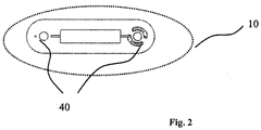
- the segment 10 itself consists of at least one impedance element 20, an insulated support 30 and connection system 40. Said connection system serves for mechanical purpose and for conductive segments interconnection.
- connection system allows to:
- the impedance 20 can be placed on one side, both sides or alternately on one and the other side of the insulation support 30. Except of space benefit the said device has following advantages:
- connection system 40 consists of special connection features provided on insulating support 30.
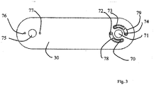
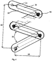
- Such connection system 40 has basically two ends. At both ends of insulating support 30, the connection system has a hole 75 and 71, through which the segments are fixed to each other. Fixation could be made by rivet or screw, which passes through the hole 75 of one segment and hole 71 of another segment, or by other connection means. By tightening two segments e.g. by the screw, one can fix the angle 50 between mentioned segments 10 and thus set required height and width 60 of the final assembly.
- impedance elements 20 are located under set angle 50 which is smaller then 180°. This arrangement will also result in longer creepage distance of the functional parts comparing to the standard solution used in Fig. 1 , which can give bigger dielectric behavior.
- Insulating support 30 has in addition two small holes 76 and 77.
- the output wire 21 from impedance element 20 passes through one of these holes, depending on size and configuration of selected impedance element 20.
- Oval opening 70 allows soldering of resistive element 20 in a place that is the most suitable for set angle 50.
- conductive element 79 could be used instead of conductive element 78 and/or hole 76 could be used instead of hole 77 on the other side of insulating support 30.
- connection system 40 allows to place impedance
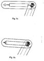
- connection with gap can be used in case the impedance elements are not too long. In such a case all impedances could be placed on the same side of all segments as there is no space constraint. Alternating sides placement could be applied as well, in order to get e.g. better power dissipation from impedance elements used.
- crossed connection according to Fig. 5b can be preferably used.
- alternating side placement might be the only possible placement of impedance elements 20 in order to have the smallest width of final assembly.
- Fig. 6 shows only example of two segments forming fixed configuration, but there could be also 3 segments in "Z" configuration, etc., with possibility to have more and more branches of the final configuration) forming a single body/support which does not need and does not have the possibility to be adjusted.
- Such fixed support if produced as standard part, can be further height reduced by breaking or cutting off the unused part of said support.
- impedance elements In order to reach required value if impedances required for voltage divider, impedance elements could be assembled to the segments 10 and these segments connected in series, thus increasing total impedance of the divider. In order to decrease production costs or to improve power withstand, it can be advantageous to use standard, and thus cheaper, impedance elements which are connected within given segment in parallel and/or in series, providing required impedance value.
Landscapes
- Physics & Mathematics (AREA)
- General Physics & Mathematics (AREA)
- Engineering & Computer Science (AREA)
- Power Engineering (AREA)
- Measuring Instrument Details And Bridges, And Automatic Balancing Devices (AREA)
- Measurement Of Current Or Voltage (AREA)
Claims (1)
- Spannungssensoreinrichtung mit einem Hochspannungsteil (1) und einem Niederspannungsteil (2), wobei die Spannungssensoreinrichtung umfasst:- mehrere Segmente (10); und- mehrere Impedanzelemente (20);wobei der Hochspannungsteil aus mindestens einem Segment gebildet wird und der Niederspannungsteil aus mindestens einem Segment gebildet wird;wobei jedes Segment mindestens ein Impedanzelement, einen isolierten Träger (30) und ein Verbindungssystem (40) umfasst;wobei das Verbindungssystem für jedes Segment einen ersten Teil an einem ersten Ende jedes Segments und einen zweiten Teil an einem zweiten Ende jedes Segments aufweist;wobei das Verbindungssystem ausgelegt ist zum mechanischem Verbinden benachbarter Paare von Segmenten miteinander und das Verbindungssystem ausgelegt ist zum elektrischen Verbinden des mindestens einen Impedanzelements von benachbarten Paaren von Segmenten miteinander, wobei ein erster Teil des Verbindungssystems eines Segments von benachbarten Paaren von Segmenten ausgelegt ist zum Verbinden mit einem zweiten Teil des Verbindungssystems eines zweiten Segments von benachbarten Paaren von Segmenten;wobei das Verbindungssystem ausgelegt ist, um zu ermöglichen, dass der Winkel zwischen benachbarten Paaren von Segmenten verändert wird;dadurch gekennzeichnet, dassdie Impedanzelemente entweder kapazitive Elemente oder eine Kombination aus resistiven Elementen und kapazitiven Elementen sind; unddie Impedanzelemente innerhalb mindestens eines Segments parallel geschaltet sind und die Impedanzelemente innerhalb mindestens eines anderen Segments in Reihe geschaltet sind.
Priority Applications (5)
| Application Number | Priority Date | Filing Date | Title |
|---|---|---|---|
| EP13003868.0A EP2833154B1 (de) | 2013-08-02 | 2013-08-02 | Spannungssensorvorrichtung |
| ARP140102787A AR097077A1 (es) | 2013-08-02 | 2014-07-25 | Dispositivo sensor de tensión |
| BR102014018821A BR102014018821A8 (pt) | 2013-08-02 | 2014-07-30 | Dispositivo de detecção de tensão |
| CN201410470258.8A CN104345205B (zh) | 2013-08-02 | 2014-08-01 | 电压传感器设备 |
| US14/450,351 US9797930B2 (en) | 2013-08-02 | 2014-08-04 | Voltage sensor device |
Applications Claiming Priority (1)
| Application Number | Priority Date | Filing Date | Title |
|---|---|---|---|
| EP13003868.0A EP2833154B1 (de) | 2013-08-02 | 2013-08-02 | Spannungssensorvorrichtung |
Publications (2)
| Publication Number | Publication Date |
|---|---|
| EP2833154A1 EP2833154A1 (de) | 2015-02-04 |
| EP2833154B1 true EP2833154B1 (de) | 2022-04-06 |
Family
ID=48915818
Family Applications (1)
| Application Number | Title | Priority Date | Filing Date |
|---|---|---|---|
| EP13003868.0A Active EP2833154B1 (de) | 2013-08-02 | 2013-08-02 | Spannungssensorvorrichtung |
Country Status (5)
| Country | Link |
|---|---|
| US (1) | US9797930B2 (de) |
| EP (1) | EP2833154B1 (de) |
| CN (1) | CN104345205B (de) |
| AR (1) | AR097077A1 (de) |
| BR (1) | BR102014018821A8 (de) |
Families Citing this family (1)
| Publication number | Priority date | Publication date | Assignee | Title |
|---|---|---|---|---|
| EP3570047A1 (de) * | 2018-05-15 | 2019-11-20 | 3M Innovative Properties Company | Modul und system zum aufbau eines spannungsteilers zur messung einer spannung |
Citations (1)
| Publication number | Priority date | Publication date | Assignee | Title |
|---|---|---|---|---|
| EP2605023A1 (de) * | 2011-12-16 | 2013-06-19 | Arteche Lantegi Elkartea, S.A. | Hochspannungsteiler und Stecker mit besagtem Teiler |
Family Cites Families (8)
| Publication number | Priority date | Publication date | Assignee | Title |
|---|---|---|---|---|
| DE606438C (de) * | 1934-12-05 | Metallgesellschaft Ag | Hochspannungsmessinstrument fuer Wechsel- oder Gleichspannungen | |
| US1047742A (en) * | 1912-03-18 | 1912-12-17 | Frank Buchanan | Electrical resistance. |
| EP1015895B1 (de) * | 1997-09-16 | 2001-07-11 | Trench Switzerland AG | Spannungsteiler |
| FI106226B (fi) * | 1999-05-17 | 2000-12-15 | Abb Corporate Res Oy | Resistiivinen jänniteanturi |
| US7397233B2 (en) * | 2004-01-07 | 2008-07-08 | Suparules Limited | Voltage measuring device |
| US7129693B2 (en) * | 2004-07-19 | 2006-10-31 | Fieldmetrics, Inc. | Modular voltage sensor |
| CN201163287Y (zh) * | 2007-08-01 | 2008-12-10 | 大连新大路电气传动技术有限责任公司 | 具有支撑绝缘子功能的高压型电压传感器 |
| FR3003354B1 (fr) * | 2013-03-12 | 2015-04-17 | Alstom Technology Ltd | Element resistif, module rc et diviseur en tension rc pour poste electrique haute tension isole par un fluide dielectrique |
-
2013
- 2013-08-02 EP EP13003868.0A patent/EP2833154B1/de active Active
-
2014
- 2014-07-25 AR ARP140102787A patent/AR097077A1/es unknown
- 2014-07-30 BR BR102014018821A patent/BR102014018821A8/pt not_active Application Discontinuation
- 2014-08-01 CN CN201410470258.8A patent/CN104345205B/zh active Active
- 2014-08-04 US US14/450,351 patent/US9797930B2/en active Active
Patent Citations (1)
| Publication number | Priority date | Publication date | Assignee | Title |
|---|---|---|---|---|
| EP2605023A1 (de) * | 2011-12-16 | 2013-06-19 | Arteche Lantegi Elkartea, S.A. | Hochspannungsteiler und Stecker mit besagtem Teiler |
Also Published As
| Publication number | Publication date |
|---|---|
| US20150035553A1 (en) | 2015-02-05 |
| CN104345205B (zh) | 2018-11-20 |
| EP2833154A1 (de) | 2015-02-04 |
| BR102014018821A2 (pt) | 2015-09-29 |
| US9797930B2 (en) | 2017-10-24 |
| CN104345205A (zh) | 2015-02-11 |
| BR102014018821A8 (pt) | 2017-12-19 |
| AR097077A1 (es) | 2016-02-17 |
Similar Documents
| Publication | Publication Date | Title |
|---|---|---|
| US7666033B1 (en) | Power plug with over temperature and over current protection | |
| RU2016107879A (ru) | Охлаждающее устройство для электрического или электронного устройства и электрическое или электронное устройство, в частности автоматический выключатель, содержащий такое охлаждающее устройство | |
| JP2014203893A (ja) | コンデンサモジュール | |
| RU2009147822A (ru) | Устройство с крупным электронагреваемым сотовым элементом | |
| US8314677B1 (en) | Overcurrent protective wire wound resistor | |
| CN106463293A (zh) | 电气开关装置及用于其的跳线和相关方法 | |
| JP2019140310A5 (de) | ||
| BR102014032286B1 (pt) | Adaptador de barramento e sistema com barramentos e um adaptador de barramento | |
| KR20150143461A (ko) | 다극형 퓨저블 링크 | |
| CN109314470A (zh) | 将至少一个电构件与第一和第二汇流排电连接的装置 | |
| DE502007004867D1 (de) | Einschaltwiderstand für Hochspannungsleistungsschalter | |
| US9797930B2 (en) | Voltage sensor device | |
| KR20160022182A (ko) | 퓨즈가 일체화된 저항기 | |
| EP3470367B1 (de) | Ozongenerator | |
| JP4550114B2 (ja) | 高性能負荷抵抗体 | |
| EP2991110B1 (de) | Vorrichtung zum schutz von schaltkreisen | |
| CN105762028B (zh) | 一种断路器的触臂和制造该触臂的方法 | |
| CN102723245B (zh) | 一种高压断路器用电阻装置及高压断路器 | |
| US9799423B2 (en) | Cable and method of manufacturing the same | |
| CN110648782B (zh) | 铜导体 | |
| US10002693B2 (en) | High-power compact electrical resistor | |
| KR20130004167A (ko) | 스크린-브레이크 접합부를 갖는 전선 | |
| CN206076520U (zh) | 一种防雷器连接装置 | |
| US813538A (en) | Connector for electrical conductors. | |
| JP6474277B2 (ja) | 3極式配電機器の分岐バーセット |
Legal Events
| Date | Code | Title | Description |
|---|---|---|---|
| 17P | Request for examination filed |
Effective date: 20130802 |
|
| AK | Designated contracting states |
Kind code of ref document: A1 Designated state(s): AL AT BE BG CH CY CZ DE DK EE ES FI FR GB GR HR HU IE IS IT LI LT LU LV MC MK MT NL NO PL PT RO RS SE SI SK SM TR |
|
| AX | Request for extension of the european patent |
Extension state: BA ME |
|
| PUAI | Public reference made under article 153(3) epc to a published international application that has entered the european phase |
Free format text: ORIGINAL CODE: 0009012 |
|
| R17P | Request for examination filed (corrected) |
Effective date: 20150803 |
|
| RBV | Designated contracting states (corrected) |
Designated state(s): AL AT BE BG CH CY CZ DE DK EE ES FI FR GB GR HR HU IE IS IT LI LT LU LV MC MK MT NL NO PL PT RO RS SE SI SK SM TR |
|
| 17Q | First examination report despatched |
Effective date: 20150909 |
|
| RAP1 | Party data changed (applicant data changed or rights of an application transferred) |
Owner name: ABB SCHWEIZ AG |
|
| STAA | Information on the status of an ep patent application or granted ep patent |
Free format text: STATUS: EXAMINATION IS IN PROGRESS |
|
| GRAP | Despatch of communication of intention to grant a patent |
Free format text: ORIGINAL CODE: EPIDOSNIGR1 |
|
| STAA | Information on the status of an ep patent application or granted ep patent |
Free format text: STATUS: GRANT OF PATENT IS INTENDED |
|
| INTG | Intention to grant announced |
Effective date: 20211119 |
|
| GRAS | Grant fee paid |
Free format text: ORIGINAL CODE: EPIDOSNIGR3 |
|
| GRAA | (expected) grant |
Free format text: ORIGINAL CODE: 0009210 |
|
| STAA | Information on the status of an ep patent application or granted ep patent |
Free format text: STATUS: THE PATENT HAS BEEN GRANTED |
|
| RIN1 | Information on inventor provided before grant (corrected) |
Inventor name: PAVLAS, MAREK Inventor name: PODZEMNY, JAROMIR Inventor name: JAVORA, RADEK Inventor name: HRABCIK, MIROSLAV |
|
| AK | Designated contracting states |
Kind code of ref document: B1 Designated state(s): AL AT BE BG CH CY CZ DE DK EE ES FI FR GB GR HR HU IE IS IT LI LT LU LV MC MK MT NL NO PL PT RO RS SE SI SK SM TR |
|
| RAP3 | Party data changed (applicant data changed or rights of an application transferred) |
Owner name: ABB SCHWEIZ AG |
|
| REG | Reference to a national code |
Ref country code: GB Ref legal event code: FG4D |
|
| REG | Reference to a national code |
Ref country code: CH Ref legal event code: EP |
|
| REG | Reference to a national code |
Ref country code: AT Ref legal event code: REF Ref document number: 1481829 Country of ref document: AT Kind code of ref document: T Effective date: 20220415 |
|
| REG | Reference to a national code |
Ref country code: DE Ref legal event code: R096 Ref document number: 602013081303 Country of ref document: DE |
|
| REG | Reference to a national code |
Ref country code: IE Ref legal event code: FG4D |
|
| REG | Reference to a national code |
Ref country code: LT Ref legal event code: MG9D |
|
| REG | Reference to a national code |
Ref country code: NL Ref legal event code: MP Effective date: 20220406 |
|
| PG25 | Lapsed in a contracting state [announced via postgrant information from national office to epo] |
Ref country code: NL Free format text: LAPSE BECAUSE OF FAILURE TO SUBMIT A TRANSLATION OF THE DESCRIPTION OR TO PAY THE FEE WITHIN THE PRESCRIBED TIME-LIMIT Effective date: 20220406 |
|
| PG25 | Lapsed in a contracting state [announced via postgrant information from national office to epo] |
Ref country code: SE Free format text: LAPSE BECAUSE OF FAILURE TO SUBMIT A TRANSLATION OF THE DESCRIPTION OR TO PAY THE FEE WITHIN THE PRESCRIBED TIME-LIMIT Effective date: 20220406 Ref country code: PT Free format text: LAPSE BECAUSE OF FAILURE TO SUBMIT A TRANSLATION OF THE DESCRIPTION OR TO PAY THE FEE WITHIN THE PRESCRIBED TIME-LIMIT Effective date: 20220808 Ref country code: NO Free format text: LAPSE BECAUSE OF FAILURE TO SUBMIT A TRANSLATION OF THE DESCRIPTION OR TO PAY THE FEE WITHIN THE PRESCRIBED TIME-LIMIT Effective date: 20220706 Ref country code: LT Free format text: LAPSE BECAUSE OF FAILURE TO SUBMIT A TRANSLATION OF THE DESCRIPTION OR TO PAY THE FEE WITHIN THE PRESCRIBED TIME-LIMIT Effective date: 20220406 Ref country code: HR Free format text: LAPSE BECAUSE OF FAILURE TO SUBMIT A TRANSLATION OF THE DESCRIPTION OR TO PAY THE FEE WITHIN THE PRESCRIBED TIME-LIMIT Effective date: 20220406 Ref country code: GR Free format text: LAPSE BECAUSE OF FAILURE TO SUBMIT A TRANSLATION OF THE DESCRIPTION OR TO PAY THE FEE WITHIN THE PRESCRIBED TIME-LIMIT Effective date: 20220707 Ref country code: FI Free format text: LAPSE BECAUSE OF FAILURE TO SUBMIT A TRANSLATION OF THE DESCRIPTION OR TO PAY THE FEE WITHIN THE PRESCRIBED TIME-LIMIT Effective date: 20220406 Ref country code: ES Free format text: LAPSE BECAUSE OF FAILURE TO SUBMIT A TRANSLATION OF THE DESCRIPTION OR TO PAY THE FEE WITHIN THE PRESCRIBED TIME-LIMIT Effective date: 20220406 Ref country code: BG Free format text: LAPSE BECAUSE OF FAILURE TO SUBMIT A TRANSLATION OF THE DESCRIPTION OR TO PAY THE FEE WITHIN THE PRESCRIBED TIME-LIMIT Effective date: 20220706 |
|
| PG25 | Lapsed in a contracting state [announced via postgrant information from national office to epo] |
Ref country code: RS Free format text: LAPSE BECAUSE OF FAILURE TO SUBMIT A TRANSLATION OF THE DESCRIPTION OR TO PAY THE FEE WITHIN THE PRESCRIBED TIME-LIMIT Effective date: 20220406 Ref country code: PL Free format text: LAPSE BECAUSE OF FAILURE TO SUBMIT A TRANSLATION OF THE DESCRIPTION OR TO PAY THE FEE WITHIN THE PRESCRIBED TIME-LIMIT Effective date: 20220406 Ref country code: LV Free format text: LAPSE BECAUSE OF FAILURE TO SUBMIT A TRANSLATION OF THE DESCRIPTION OR TO PAY THE FEE WITHIN THE PRESCRIBED TIME-LIMIT Effective date: 20220406 Ref country code: IS Free format text: LAPSE BECAUSE OF FAILURE TO SUBMIT A TRANSLATION OF THE DESCRIPTION OR TO PAY THE FEE WITHIN THE PRESCRIBED TIME-LIMIT Effective date: 20220806 |
|
| REG | Reference to a national code |
Ref country code: DE Ref legal event code: R097 Ref document number: 602013081303 Country of ref document: DE |
|
| PG25 | Lapsed in a contracting state [announced via postgrant information from national office to epo] |
Ref country code: SM Free format text: LAPSE BECAUSE OF FAILURE TO SUBMIT A TRANSLATION OF THE DESCRIPTION OR TO PAY THE FEE WITHIN THE PRESCRIBED TIME-LIMIT Effective date: 20220406 Ref country code: SK Free format text: LAPSE BECAUSE OF FAILURE TO SUBMIT A TRANSLATION OF THE DESCRIPTION OR TO PAY THE FEE WITHIN THE PRESCRIBED TIME-LIMIT Effective date: 20220406 Ref country code: RO Free format text: LAPSE BECAUSE OF FAILURE TO SUBMIT A TRANSLATION OF THE DESCRIPTION OR TO PAY THE FEE WITHIN THE PRESCRIBED TIME-LIMIT Effective date: 20220406 Ref country code: EE Free format text: LAPSE BECAUSE OF FAILURE TO SUBMIT A TRANSLATION OF THE DESCRIPTION OR TO PAY THE FEE WITHIN THE PRESCRIBED TIME-LIMIT Effective date: 20220406 Ref country code: DK Free format text: LAPSE BECAUSE OF FAILURE TO SUBMIT A TRANSLATION OF THE DESCRIPTION OR TO PAY THE FEE WITHIN THE PRESCRIBED TIME-LIMIT Effective date: 20220406 Ref country code: CZ Free format text: LAPSE BECAUSE OF FAILURE TO SUBMIT A TRANSLATION OF THE DESCRIPTION OR TO PAY THE FEE WITHIN THE PRESCRIBED TIME-LIMIT Effective date: 20220406 |
|
| PLBE | No opposition filed within time limit |
Free format text: ORIGINAL CODE: 0009261 |
|
| STAA | Information on the status of an ep patent application or granted ep patent |
Free format text: STATUS: NO OPPOSITION FILED WITHIN TIME LIMIT |
|
| 26N | No opposition filed |
Effective date: 20230110 |
|
| PG25 | Lapsed in a contracting state [announced via postgrant information from national office to epo] |
Ref country code: MC Free format text: LAPSE BECAUSE OF FAILURE TO SUBMIT A TRANSLATION OF THE DESCRIPTION OR TO PAY THE FEE WITHIN THE PRESCRIBED TIME-LIMIT Effective date: 20220406 Ref country code: AL Free format text: LAPSE BECAUSE OF FAILURE TO SUBMIT A TRANSLATION OF THE DESCRIPTION OR TO PAY THE FEE WITHIN THE PRESCRIBED TIME-LIMIT Effective date: 20220406 |
|
| REG | Reference to a national code |
Ref country code: CH Ref legal event code: PL |
|
| GBPC | Gb: european patent ceased through non-payment of renewal fee |
Effective date: 20220802 |
|
| PG25 | Lapsed in a contracting state [announced via postgrant information from national office to epo] |
Ref country code: LU Free format text: LAPSE BECAUSE OF NON-PAYMENT OF DUE FEES Effective date: 20220802 Ref country code: LI Free format text: LAPSE BECAUSE OF NON-PAYMENT OF DUE FEES Effective date: 20220831 Ref country code: CH Free format text: LAPSE BECAUSE OF NON-PAYMENT OF DUE FEES Effective date: 20220831 |
|
| REG | Reference to a national code |
Ref country code: BE Ref legal event code: MM Effective date: 20220831 |
|
| PG25 | Lapsed in a contracting state [announced via postgrant information from national office to epo] |
Ref country code: SI Free format text: LAPSE BECAUSE OF FAILURE TO SUBMIT A TRANSLATION OF THE DESCRIPTION OR TO PAY THE FEE WITHIN THE PRESCRIBED TIME-LIMIT Effective date: 20220406 |
|
| REG | Reference to a national code |
Ref country code: AT Ref legal event code: UEP Ref document number: 1481829 Country of ref document: AT Kind code of ref document: T Effective date: 20220406 |
|
| PG25 | Lapsed in a contracting state [announced via postgrant information from national office to epo] |
Ref country code: IE Free format text: LAPSE BECAUSE OF NON-PAYMENT OF DUE FEES Effective date: 20220802 |
|
| PG25 | Lapsed in a contracting state [announced via postgrant information from national office to epo] |
Ref country code: BE Free format text: LAPSE BECAUSE OF NON-PAYMENT OF DUE FEES Effective date: 20220831 |
|
| PG25 | Lapsed in a contracting state [announced via postgrant information from national office to epo] |
Ref country code: GB Free format text: LAPSE BECAUSE OF NON-PAYMENT OF DUE FEES Effective date: 20220802 |
|
| PG25 | Lapsed in a contracting state [announced via postgrant information from national office to epo] |
Ref country code: HU Free format text: LAPSE BECAUSE OF FAILURE TO SUBMIT A TRANSLATION OF THE DESCRIPTION OR TO PAY THE FEE WITHIN THE PRESCRIBED TIME-LIMIT; INVALID AB INITIO Effective date: 20130802 |
|
| PG25 | Lapsed in a contracting state [announced via postgrant information from national office to epo] |
Ref country code: MK Free format text: LAPSE BECAUSE OF FAILURE TO SUBMIT A TRANSLATION OF THE DESCRIPTION OR TO PAY THE FEE WITHIN THE PRESCRIBED TIME-LIMIT Effective date: 20220406 Ref country code: CY Free format text: LAPSE BECAUSE OF FAILURE TO SUBMIT A TRANSLATION OF THE DESCRIPTION OR TO PAY THE FEE WITHIN THE PRESCRIBED TIME-LIMIT Effective date: 20220406 |
|
| PG25 | Lapsed in a contracting state [announced via postgrant information from national office to epo] |
Ref country code: TR Free format text: LAPSE BECAUSE OF FAILURE TO SUBMIT A TRANSLATION OF THE DESCRIPTION OR TO PAY THE FEE WITHIN THE PRESCRIBED TIME-LIMIT Effective date: 20220406 |
|
| PG25 | Lapsed in a contracting state [announced via postgrant information from national office to epo] |
Ref country code: MT Free format text: LAPSE BECAUSE OF FAILURE TO SUBMIT A TRANSLATION OF THE DESCRIPTION OR TO PAY THE FEE WITHIN THE PRESCRIBED TIME-LIMIT Effective date: 20220406 |
|
| PG25 | Lapsed in a contracting state [announced via postgrant information from national office to epo] |
Ref country code: BG Free format text: LAPSE BECAUSE OF FAILURE TO SUBMIT A TRANSLATION OF THE DESCRIPTION OR TO PAY THE FEE WITHIN THE PRESCRIBED TIME-LIMIT Effective date: 20220406 |
|
| PG25 | Lapsed in a contracting state [announced via postgrant information from national office to epo] |
Ref country code: BG Free format text: LAPSE BECAUSE OF FAILURE TO SUBMIT A TRANSLATION OF THE DESCRIPTION OR TO PAY THE FEE WITHIN THE PRESCRIBED TIME-LIMIT Effective date: 20220406 |
|
| PGFP | Annual fee paid to national office [announced via postgrant information from national office to epo] |
Ref country code: DE Payment date: 20250820 Year of fee payment: 13 |
|
| PGFP | Annual fee paid to national office [announced via postgrant information from national office to epo] |
Ref country code: IT Payment date: 20250825 Year of fee payment: 13 |
|
| PGFP | Annual fee paid to national office [announced via postgrant information from national office to epo] |
Ref country code: FR Payment date: 20250829 Year of fee payment: 13 Ref country code: AT Payment date: 20250821 Year of fee payment: 13 |