EP2833476B1 - Appareil de mesure de volume d'écoulement - Google Patents
Appareil de mesure de volume d'écoulement Download PDFInfo
- Publication number
- EP2833476B1 EP2833476B1 EP13767755.5A EP13767755A EP2833476B1 EP 2833476 B1 EP2833476 B1 EP 2833476B1 EP 13767755 A EP13767755 A EP 13767755A EP 2833476 B1 EP2833476 B1 EP 2833476B1
- Authority
- EP
- European Patent Office
- Prior art keywords
- housing
- radiation conductor
- conductive
- electrically
- circuit board
- Prior art date
- Legal status (The legal status is an assumption and is not a legal conclusion. Google has not performed a legal analysis and makes no representation as to the accuracy of the status listed.)
- Active
Links
Images


Classifications
-
- G—PHYSICS
- G01—MEASURING; TESTING
- G01D—MEASURING NOT SPECIALLY ADAPTED FOR A SPECIFIC VARIABLE; ARRANGEMENTS FOR MEASURING TWO OR MORE VARIABLES NOT COVERED IN A SINGLE OTHER SUBCLASS; TARIFF METERING APPARATUS; MEASURING OR TESTING NOT OTHERWISE PROVIDED FOR
- G01D4/00—Tariff metering apparatus
- G01D4/002—Remote reading of utility meters
- G01D4/006—Remote reading of utility meters to a non-fixed location, i.e. mobile location
-
- G—PHYSICS
- G01—MEASURING; TESTING
- G01F—MEASURING VOLUME, VOLUME FLOW, MASS FLOW OR LIQUID LEVEL; METERING BY VOLUME
- G01F15/00—Details of, or accessories for, apparatus of groups G01F1/00 - G01F13/00 insofar as such details or appliances are not adapted to particular types of such apparatus
- G01F15/06—Indicating or recording devices
- G01F15/061—Indicating or recording devices for remote indication
- G01F15/063—Indicating or recording devices for remote indication using electrical means
-
- H—ELECTRICITY
- H01—ELECTRIC ELEMENTS
- H01Q—ANTENNAS, i.e. RADIO AERIALS
- H01Q1/00—Details of, or arrangements associated with, antennas
- H01Q1/12—Supports; Mounting means
- H01Q1/22—Supports; Mounting means by structural association with other equipment or articles
- H01Q1/2208—Supports; Mounting means by structural association with other equipment or articles associated with components used in interrogation type services, i.e. in systems for information exchange between an interrogator/reader and a tag/transponder, e.g. in Radio Frequency Identification [RFID] systems
- H01Q1/2233—Supports; Mounting means by structural association with other equipment or articles associated with components used in interrogation type services, i.e. in systems for information exchange between an interrogator/reader and a tag/transponder, e.g. in Radio Frequency Identification [RFID] systems used in consumption-meter devices, e.g. electricity, gas or water meters
-
- H—ELECTRICITY
- H01—ELECTRIC ELEMENTS
- H01Q—ANTENNAS, i.e. RADIO AERIALS
- H01Q1/00—Details of, or arrangements associated with, antennas
- H01Q1/12—Supports; Mounting means
- H01Q1/22—Supports; Mounting means by structural association with other equipment or articles
- H01Q1/225—Supports; Mounting means by structural association with other equipment or articles used in level-measurement devices, e.g. for level gauge measurement
-
- H—ELECTRICITY
- H01—ELECTRIC ELEMENTS
- H01Q—ANTENNAS, i.e. RADIO AERIALS
- H01Q1/00—Details of, or arrangements associated with, antennas
- H01Q1/48—Earthing means; Earth screens; Counterpoises
-
- H—ELECTRICITY
- H01—ELECTRIC ELEMENTS
- H01Q—ANTENNAS, i.e. RADIO AERIALS
- H01Q9/00—Electrically-short antennas having dimensions not more than twice the operating wavelength and consisting of conductive active radiating elements
- H01Q9/04—Resonant antennas
- H01Q9/30—Resonant antennas with feed to end of elongated active element, e.g. unipole
- H01Q9/32—Vertical arrangement of element
- H01Q9/36—Vertical arrangement of element with top loading
-
- H—ELECTRICITY
- H01—ELECTRIC ELEMENTS
- H01Q—ANTENNAS, i.e. RADIO AERIALS
- H01Q9/00—Electrically-short antennas having dimensions not more than twice the operating wavelength and consisting of conductive active radiating elements
- H01Q9/04—Resonant antennas
- H01Q9/30—Resonant antennas with feed to end of elongated active element, e.g. unipole
- H01Q9/42—Resonant antennas with feed to end of elongated active element, e.g. unipole with folded element, the folded parts being spaced apart a small fraction of the operating wavelength
-
- G—PHYSICS
- G01—MEASURING; TESTING
- G01D—MEASURING NOT SPECIALLY ADAPTED FOR A SPECIFIC VARIABLE; ARRANGEMENTS FOR MEASURING TWO OR MORE VARIABLES NOT COVERED IN A SINGLE OTHER SUBCLASS; TARIFF METERING APPARATUS; MEASURING OR TESTING NOT OTHERWISE PROVIDED FOR
- G01D11/00—Component parts of measuring arrangements not specially adapted for a specific variable
- G01D11/24—Housings ; Casings for instruments
- G01D11/245—Housings for sensors
-
- Y—GENERAL TAGGING OF NEW TECHNOLOGICAL DEVELOPMENTS; GENERAL TAGGING OF CROSS-SECTIONAL TECHNOLOGIES SPANNING OVER SEVERAL SECTIONS OF THE IPC; TECHNICAL SUBJECTS COVERED BY FORMER USPC CROSS-REFERENCE ART COLLECTIONS [XRACs] AND DIGESTS
- Y02—TECHNOLOGIES OR APPLICATIONS FOR MITIGATION OR ADAPTATION AGAINST CLIMATE CHANGE
- Y02B—CLIMATE CHANGE MITIGATION TECHNOLOGIES RELATED TO BUILDINGS, e.g. HOUSING, HOUSE APPLIANCES OR RELATED END-USER APPLICATIONS
- Y02B90/00—Enabling technologies or technologies with a potential or indirect contribution to GHG emissions mitigation
- Y02B90/20—Smart grids as enabling technology in buildings sector
-
- Y—GENERAL TAGGING OF NEW TECHNOLOGICAL DEVELOPMENTS; GENERAL TAGGING OF CROSS-SECTIONAL TECHNOLOGIES SPANNING OVER SEVERAL SECTIONS OF THE IPC; TECHNICAL SUBJECTS COVERED BY FORMER USPC CROSS-REFERENCE ART COLLECTIONS [XRACs] AND DIGESTS
- Y04—INFORMATION OR COMMUNICATION TECHNOLOGIES HAVING AN IMPACT ON OTHER TECHNOLOGY AREAS
- Y04S—SYSTEMS INTEGRATING TECHNOLOGIES RELATED TO POWER NETWORK OPERATION, COMMUNICATION OR INFORMATION TECHNOLOGIES FOR IMPROVING THE ELECTRICAL POWER GENERATION, TRANSMISSION, DISTRIBUTION, MANAGEMENT OR USAGE, i.e. SMART GRIDS
- Y04S20/00—Management or operation of end-user stationary applications or the last stages of power distribution; Controlling, monitoring or operating thereof
- Y04S20/30—Smart metering, e.g. specially adapted for remote reading
Definitions
- the present invention relates to a flow meter device. Particularly, the present invention relates to a flow meter device which measures the flow (flow rate) of a target.
- the radio adapter slave device disclosed in Patent Literature 1 contains therein a board mounted planar antenna.
- a ground conductor plate and a short conductor of a radio conductor unit are connected to each other via a wire pattern of a printed circuit board. This ground conductor plate is used as a ground of the radio conductor unit.
- Patent Literature 1 Japanese Laid-Open Patent Application Publication No. Hei 10-313212
- Document EP-A-0718908 discloses an RF transmitter with an impedance matching circuit.
- a battery provides power to the positive operating voltage line and the ground, but is decoupled from both of these lines by impedances.
- the metal connected to one terminal of the battery acts as antenna radiating the transmitting circuit output signal.
- the coupling impedance acts as an antenna extension coil so that no separate antenna is required. This way, the size can be reduced and it can be mounted in or on a meter.
- Document US-A-6115677 discloses a meter device with a radio module connected.
- a planar antenna is mounted inside a non-metallic housing cover of the meter. The meter is mounted on a wall, and the main radiation direction of the planar antenna is perpendicularly away from the wall. This makes the meter especially suited for centrally supplied dwellings or offices. Consumption measurement is achieved by the wireless system.
- the size of the ground conductor unit is not sufficiently large for the wavelength of a radio frequency (RF) signal used in radio (wireless) communication.
- the ground conductor unit is affected by metal existing in its vicinity. This may degrade antenna characteristics such as a gain and a radiation efficiency.
- the size of the radio adapter slave device may increase in size.
- the ground conductor plate is provided as dedicated to the ground of the radio conductor unit, the size of the radio adapter slave device increases.
- the present invention has been made to solve the above described problem, and an object of the present invention is to provide a small-sized flow meter device which improves antenna characteristics as compared to a conventional example.
- a flow meter device comprises a housing which is formed of an electrically-conductive material and accommodates therein a sensor for detecting a flow of a target; a radiation conductor which radiates an electric wave of a radio frequency signal; a circuit board which is electrically connected to the radiation conductor and in which a power supplying circuit for supplying radio-frequency electric power of the radio frequency signal to the radiation conductor is mounted; a casing which is formed of a non-electrically-conductive material, is placed on the housing, and accommodates therein the radiation conductor and the circuit board; and a connecting member which is formed of the electrically-conductive material and electrically connects the housing and a ground of the circuit board to each other.
- the present invention has the above described configuration and can achieve advantages that it is possible to provide a small-sized flow meter device which improves antenna characteristics as compared to a conventional example.
- a flow meter device comprises a housing which is formed of an electrically-conductive material and accommodates therein a sensor for detecting a flow of a target; a radiation conductor which radiates an electric wave of a radio frequency signal; a circuit board which is electrically connected to the radiation conductor and in which a power supplying circuit for supplying radio-frequency electric power of the radio frequency signal to the radiation conductor is mounted; a casing which is formed of a non-electrically-conductive material, is placed on the housing, and accommodates therein the radiation conductor and the circuit board; and a connecting member which is formed of the electrically-conductive material and electrically connects the housing and a ground of the power supplying circuit to each other.
- the flow meter device may further comprise a conductive member which is accommodated in the casing and electrically connected to the power supplying circuit; and a radio frequency isolating circuit which is disposed between the power supplying circuit and the conductive member and electrically isolates the power supplying circuit from the conductive member with respect to the radio frequency signal.
- the radio frequency isolating circuit may include a parallel resonant circuit which resonates with the radio frequency signal and increases an impedance.
- the radio frequency isolating circuit may include a photo coupler for electrically insulating the power supplying circuit from the conductive member.
- the circuit board includes a power supplying point at which the power supplying circuit and the radiation conductor are electrically connected to each other, and the connecting member is placed in the vicinity of the power supplying point and on an opposite side of the radiation conductor with respect to the power supplying point.
- the flow meter device may further comprise a conductive pipe which is formed of an electrically-conductive material and electrically connected to the housing; and a non-conductive pipe which is formed of a non-electrically-conductive material and coupled to the conductive pipe, wherein a length of the conductive pipe may be set based on an antenna gain of the radiation conductor.
- front For easier explanation, as shown in the drawings, "front”, “rear”, “upper”, “lower”, “right” and “left” are defined. More specifically, the direction in which a casing 20 is placed with respect to a housing 10 will be referred to “front”, and the opposite direction will be referred to as “rear.” “right” and “left” are from the perspective of the flow meter device facing forward. Furthermore, the upper and lower sides in a vertical direction will be referred to as “upper” and "lower.”
- Fig. 1 is a front view showing a flow meter device 100 according to Embodiment 1.
- Fig. 2 is a side view showing the flow meter device 100.
- Fig. 3 is a schematic front view showing the configuration of the interior of the flow meter device 100.
- Fig. 4 is a schematic side view showing the configuration of the interior of the flow meter device 100.
- the flow meter device 100 is a device which transmits, for example, data detected by a sensor 11 to a computer in a utility company of gas, electricity, or tap water via radio (wireless) communication.
- the flow meter device 100 includes a housing 10 for accommodating the sensor 11 for measuring the flow(rate) of a fluid, and a casing 20 for accommodating components which control the operation of the sensor 11, and transmit the data detected by the sensor 11 to outside.
- the housing 10 is formed of an electrically-conductive material.
- the electrically-conductive material for example, there are metal such as aluminum and stainless, and an electrically-conductive resin.
- the housing 10 has a substantially rectangular parallelepiped shape. Two pipes 12 used to flow a target into and out of the housing 10 are connected to the upper surface of the housing 10. The housing 10 accommodates the sensor 11 therein. The target flows into the housing 10 through the inflow pipe 12, then the sensor 11 detects the flow of the target, and then the target flows to outside the housing 10 through the outflow pipe 12.
- the target may be, for example, gas, tap water, or electricity.
- the housing 10 preferably has a shape in which a sum of the vertical length of the housing 10 :c and the rightward and leftward length: d of the housing 10 is ⁇ /4.
- ⁇ indicates the wavelength of an electric wave radiated from a radiation conductor 40 as will be described later.
- the casing 20 is placed on the wall surface of a front side of the housing 10 and formed of a non-electrically-conductive material.
- a non-electrically-conductive material for example, there is an electrically-insulative resin such as polypropylene or ABS.
- the casing 20 has a rectangular parallelepiped shape in which a thickness in a forward and rearward direction is smaller than a vertical dimension and a rightward and leftward dimension.
- the casing 20 is divided into front and rear parts which are a first casing 21 at a front side and a second casing 22 at a rear side.
- the casing 22 at the rear side is mounted to the front surface of the housing 10 by, for example, three first to third screws 23 to 25 and first to third nuts.
- the first screw 23 is mounted to the region of the lower portion of the second casing 22 in the vicinity of a center in the rightward and leftward direction
- the second screw 24 is mounted to the left portion of the upper portion of the second casing 22
- the third screw 25 is mounted to the right portion of the upper portion of the second casing 22.
- the first to third screws 23 to 25 and the first to third nuts are formed of the electrically-conductive material.
- the electrically-conductive material for example, there are metal such as aluminum or stainless, an electrically-conductive resin, etc..
- the screws 23 to 25 penetrate the second casing 22 from the housing 10 side.
- the heads of the screws 23 to 25 are present inside the housing 10, while the legs of the screws 23 to 25 protrude from the surface of the second casing 22.
- the second casing 22 is fastened to the housing 10 in such a manner that the nuts are attached to the legs of the screws 23 to 25, respectively.
- the first casing 21 is connected to the second casing 22 in such a manner that the first casing 21 covers the second casing 22.
- a display unit 26 is attached on the front surface of the first casing 21.
- the display unit 26 displays, for example, the flow (rate) of the target which is detected by the sensor 11.
- the second casing 22 and the first casing 21 are joined together by bonding, welding or screws.
- a space which is tightly closed and has a water seal capability is formed inside the casing 20.
- the casing 20 accommodates in this inner space, the radiation conductor 40, a radio communication circuit board 41, a measurement circuit board 27 and a battery 28.
- the housing 10, the second casing 22, the radio communication circuit board 41, the radiation conductor 40 and the first casing 21 are placed in this order in a thickness direction (i.e., forward and rearward direction) of the circuit board.
- the measurement circuit board 27 includes an integrated circuit (not shown) in which programs are mounted.
- the integrated circuit includes a signal generating circuit for generating a signal to be transmitted, based on a detection signal from the sensor 11.
- the integrated circuit operates based on the programs, and thus obtains the flow of the target such as the gas or the tap water based on the detection signal from the sensor 11.
- the obtaining method of the measurement value is not particularly limited. For example, in a case where the target is the gas, any known method such as a membrane method or an ultrasonic method may be used. It is sufficient that the programs required to calculate the measurement value based on the measurement method selected is mounted in the integrated circuit.
- the radio communication circuit board 41 is configured such that a transmission circuit for transmitting data via radio communication, a receiving circuit for processing the data received via the radio communication, a matching circuit for matching the radiation conductor 40 with the transmission circuit and the receiving circuit, etc., are mounted onto a board.
- An integrated circuit 45 which is electrically connected to the radiation conductor 40 and includes a power supplying circuit for supplying a radio frequency signal to the radiation conductor 40 is mounted onto the radio communication circuit board 41.
- the integrated circuit 45 for radio communication is electrically connected to an integrated circuit of the measurement circuit board 27 via a wire 31 and electrically connected to the radiation conductor 40.
- the integrated circuit 45 for radio communication applies an electric potential to the radiation conductor 40 according to the measurement data from the integrated circuit of the measurement circuit board 27, thereby transmitting the RF signal indicating the measurement data.
- One end of a conductive wire 43 is connected to the ground of the radio communication circuit board 41.
- the other end of the conductive wire 43 is electrically connected to the screw (in the present embodiment, first screw 23 located in the lower portion of the casing 20) closest to the radio communication circuit board 41, among the screws 23 to 25.
- the conductive wire 43 is formed of an electrically-conductive material such as copper, aluminum, or iron.
- the other end of the conductive wire 43 is wound around the leg of the first screw 23 and fastened thereto by a first bolt. This allows the conductive wire 43 to electrically connect the ground of the radio communication circuit board 41 to the first screw 23.
- the first screw 23 is electrically connected to the housing 10.
- the ground of the radio communication circuit board 41 to be electrically connected to the housing 10 via the conductive wire 43 and the screw.
- the ground of the integrated circuit 45 including the power supplying circuit is connected to the ground of the radio communication circuit board 41. Therefore, the conductive wire 43 and the first screw 23 serve as a connecting member for connecting the housing 10 to the ground of the integrated circuit 45 (power supplying circuit) of the radio communication circuit board 41. This allows the electric potential of the housing 10 to become substantially equal to that of the ground of the integrated circuit 45 of the radio communication circuit board 41.
- the housing 10 itself having a large area serves as the ground.
- a connecting position 44 at which the conductive wire 43 is connected to the ground of the radio communication circuit board 41, the conductive wire 43 and the first screw 23 are in the vicinity a power supplying point 42 as will be described later, and are on the opposite side of the radiation conductor 40 with respect to the power supplying point 42. Since the connecting position 44 and the first screw 23 are in the vicinity of the power supplying point 42, the distance from the power supplying point 42 to the housing 10 is reduced. Also, since the conductive wire 43 is placed on the opposite side of the radiation conductor 40 with respect to the power supplying point 42, it is possible to prevent the conductive wire 43 from serving as the ground for the radiation conductor 40.
- the battery 28 is an electric power supply for supplying electric power to electric components and the like mounted in the radio communication circuit board 41.
- the electric power supplied from the battery 28 is converted into RF power via the power supplying circuit 45 and supplied to the radiation conductor 40.
- the battery 28 is electrically connected to the power supplying circuit of the circuit board 41 via a wire 29, and the like.
- the radiation conductor 40 radiates as the electric wave the RF signal generated by modulation in the transmission circuit, or receives the electric wave (RF signal) from outside and delivers the electric wave to the receiving circuit for demodulating the electric wave.
- the radiation conductor 40 is an inverted-L antenna.
- the radiation conductor 40 has a thin rod shape, and is formed of an electrically-conductive material such as copper. The length of the radiation conductor 40 is set to ⁇ /4 when the wavelength of the RF signal of the radio frequency signal is ⁇ .
- the base end of the radiation conductor 40 is connected to the output section (power supplying terminal) (power feeding terminal) of the radio communication circuit board 41 at the power supplying point 42.
- the radiation conductor 40 is bent to extend in the inner space of the casing 20 so that the radiation conductor 40 is as distant as possible from the housing 10 and the constituents of the radiation conductor 40 are not close to each other. In the present example, the radiation conductor 40 is bent at four points.
- the radiation conductor 40 extends from the power supplying point 42, in a direction (forward) that is away from the housing 10, and is bent in a direction parallel to the housing 10 at a first corner in the vicinity of the front wall portion of the casing 20.
- the radiation conductor 40 extends leftward from the first corner along the lower side surface of the casing 20, and then is bent upward at a right angle at a second corner in the vicinity of the left lower corner portion of the casing 20.
- the radiation conductor 40 extends upward from the second corner along the left side surface of the casing 20, and is bent rightward at a third corner in the vicinity of the left upper corner portion of the casing 20.
- the radiation conductor 40 extends rightward from the third corner along the upper side surface of the casing 20 and is bent downward at a right angle at a fourth corner in the vicinity of the right upper corner portion of the casing 20. Then, the radiation conductor 40 extends downward from the fourth corner along the right side surface of the casing 20 to the tip end.
- the length from the front surface of the housing 10 to the first comer: a (see Fig. 2 ) is set to a largest possible value.
- the length: a is preferably larger than ⁇ /32. If the length: a is smaller than ⁇ /32, the electric potential difference between the radiation conductor 40 and the housing 10 is small, and hence the electric wave is not easily radiated from the radiation conductor 40.
- a portion of the radiation conductor 40 from the first corner to the tip end is provided to extend in parallel with the front surface of the housing 10. Therefore, the portion of the radiation conductor 40 from the first corner to the tip end faces the housing 10 with a spacing of the length : a from the housing 10.
- the target flows through the pipe 12 and the sensor 11 detects the flow of the target.
- the integrated circuit of the measurement circuit board 27 measures the flow of the target based on the detection value from the sensor 11.
- the integrated circuit 45 of the radio communication circuit board 41 creates the RF signal corresponding to the measurement value from the integrated circuit of the measurement circuit board 27 and provides the RF signal to the radiation conductor 40.
- An electric field is formed between the radiation conductor 40 and the housing 10 (and pipe 12) serving as the ground for the radiation conductor 40. This electric field changes according to the RF signal given. The change in this electric field becomes the electric wave radiated from the radiation conductor 40.
- the ground of the integrated circuit 45 of the radio communication circuit board 41 is electrically connected to the housing 10 by the connecting member including the conductive wire 43 and the first screw 23. Therefore, the housing 10 serves as the ground of the radiation conductor 40. This can eliminate a need to provide the ground dedicated to the radiation conductor 40. Therefore, cost of the components can be reduced, and the size of the flow meter device 100 can be reduced.
- the housing 10 has a largest surface area among the components formed of the electrically-conductive material which are included in the flow meter device 100. Therefore, if the frequency of the electric wave to be transmitted and received by the radiation conductor 40 is high, the ground with a sufficient size for that wavelength can be ensured. As a result, the intensity of the electric field generated between the radiation conductor 40 and the ground (housing 10) can be improved, and a gain can be improved.
- c + d The sum of the vertical length of the housing 10 and the length in the rightward and leftward direction: c + d is equal to or close to ⁇ /4. This can increase an effective area of the antenna and improve antenna characteristics.
- the connecting position 44 at which the conductive wire 43 is connected to the ground of the radio communication circuit board 41, the conductive wire 43 and the first screw 23 are in the vicinity the power supplying point 42. Thereby, the distance from the power supplying point 42 to the housing 10 is short. Therefore, the impedance of the antenna becomes low and the antenna characteristic can be improved.
- the conductive members such as the conductive wire 43 and the first screw 23, which are placed between the radio communication circuit board 41 and the housing 10 serving as the ground and electrically connected may become ground elements with respect to the radiation conductor 40. If the ground elements are close to the radiation conductor 40, the gain of the radiation conductor 40 becomes low. However, in the present embodiment, the connecting position 44 at which the conductive wire 43 is connected to the ground of the radio communication circuit board 41, the conductive wire 43 and the first screw 23 are on the opposite side of the radiation conductor 40 with respect to the power supplying point 42. Since the ground elements such as the conductive wire 43 and the first screw 23 are placed as distant as possible from the radiation conductor 40 in this way, reduction of the gain can be suppressed.
- the radio communication circuit board 41 may become the ground element of a small capacity. However, the area of the radio communication circuit board 41 is very small relative to the area of the housing 10 and the radio communication circuit board 41 is positioned relatively distant from the radiation conductor 40 (in particular, portion from the second corner to the tip end). Because of this, the housing 10 is deemed as substantially the entire ground to the radiation conductor 40, and the radio communication circuit board 41 does not substantially serve as the ground. In other words, a large part of the radio communication circuit board 41 is not deemed ground, but the housing 10 serves as the ground. Since the spacing between the radiation conductor 40 and the ground (housing 10) having a large area increases, excellent antenna characteristics can be attained.
- the radiation conductor 40, the circuit board and the housing 10 are placed in this order in the thickness direction of the circuit board. This increases the spacing between the radiation conductor 40 and the housing 10. Therefore, the frequency bandwidth of antenna can be increased and excellent antenna characteristics can be attained.
- the thickness of the flow meter device 100 can be reduced.
- the casing 20 Since the casing 20 is tightly closed (sealed), it becomes possible to prevent the radiation conductor 40, the radio communication circuit board 41 and the like from being oxidated by air, water and the like. This can prevent a change in the impedance of the radiation conductor 40, and therefore maintain stable antenna characteristics.
- a flow meter device 100 of Embodiment 2 is configured such that the flow meter device 100 of Embodiment 1 further includes parallel resonant circuits 30, 32.
- Fig. 5 is a schematic front view showing the interior of the flow meter device 100 according to Embodiment 2 of the present invention.
- the flow meter device 100 includes conductive members and a radio frequency isolating circuit.
- the conductive members are accommodated in the casing 20 and electrically connected to the radio communication circuit board 41.
- Examples of the conductive members are the battery 28, circuits other than the power supplying circuit, and a circuit board such as the measurement circuit board 27.
- the radio frequency isolating circuit is a circuit which electrically insulates (isolates) the integrated circuit 45 (power supplying circuit) from the conductive members with respect to the radio frequency (RF) signal supplied from the radio communication circuit board 41 to the radiation conductor 40.
- the radio frequency isolating circuit As the radio frequency isolating circuit, the parallel resonant circuits 30, 32 which resonate with the RF signal and increase the impedance are used.
- the parallel resonant circuits 30, 32 are placed between the radio communication circuit board 41 and the above stated conductive members.
- the resonant frequency of the parallel resonant circuits 30, 32 conforms to the frequency of the signal used in the radio communication, i.e., the RF signal supplied from the radio communication circuit board 41 to the radiation conductor 40.
- the inductance and capacitance of the parallel resonant circuits 30, 32 are set so that the frequency of the RF signal conforms to the resonant frequency. Therefore, the parallel resonant circuits 30, 32 increase the impedance with respect to the RF signal to be used.
- the parallel resonant circuit 30 is connected to the wire 29 between the battery 28 and the radio communication circuit board 41. Thereby, DC current flows from the battery 28 to the radio communication circuit board 41, but the battery 28 is isolated from the RF signal.
- the parallel resonant circuit 32 is connected to the wire 31 between the measurement circuit board 27 and the radio communication circuit board 41. Thereby, a signal is output from the measurement circuit board 27 to the radio communication circuit board 41, but the measurement circuit board 27 is isolated from the RF signal.
- the battery 28 and the measurement circuit board 27 are not deemed as the ground to the radiation conductor 40, and do not become a resistive component with respect to an electric field generated between the radiation conductor 40 and the housing 10. Because of this, this electric field is not attenuated by the battery 28 and the measurement circuit board 27, and hence degradation of the antenna characteristics which would be caused by the battery 28 and the measurement circuit board 27 is suppressed.
- the radiation conductor 40, the radio communication circuit board 41 and the housing 10 serving as the ground of the radiation conductor 40 construct an ideal circuit.
- the parallel resonant circuits 30, 32 configured as described above may be placed.
- the parallel resonant circuits 30, 32 are used as the radio frequency isolating circuit.
- a photocoupler 51 is used as the radio frequency isolating circuit.
- the parallel resonant circuit is used as the radio frequency isolating circuit.
- Fig. 6 is a schematic front view showing the interior of the flow meter device 100 according to Embodiment 3 of the present invention.
- the photocoupler 51 is used as the radio frequency isolating circuit for the measurement circuit board 27, the photocoupler 51 is used.
- the photocoupler 51 is mounted on the radio communication circuit board 41 and connected to the wire 31.
- the photocoupler 51 is disposed between the integrated circuit 45 (power supplying circuit) and the conductive member such as the measurement circuit board 27.
- the photocoupler 51 includes a light emitting element and a light receiving element, and transmits an electric signal by using light.
- the photocoupler 51 converts the electric signal from the integrated circuit of the measurement circuit board 27 into the light and emits this light by the light emitting element. Then, the photocoupler 51 receives this light by the light receiving element, converts the light into the electric signal, and outputs the electric signal to the integrated circuit 45.
- the photocoupler 51 Because of the photocoupler 51, the electric signal is not directly transmitted and received between the integrated circuit 45 of the radio communication circuit board 41 and the integrated circuit of the measurement circuit board 27. In this way, the photocoupler 51 electrically isolates the integrated circuit 45 from the measurement circuit board 27 with respect to the RF signal supplied from the radio communication circuit board 41.
- the measurement circuit board 27 is not deemed as the ground to the radiation conductor 40. Therefore, the radiation conductor 40, the radio communication circuit board 41 and the housing 10 serving as the ground of the radiation conductor 40 construct an ideal circuit.
- a flow meter device 100 of Embodiment 4 is configured such that the flow meter device 100 of Embodiment 1 further includes a pipe (conductive pipe) 14 and a pipe member (non-conductive pipe) 13.
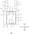
- Fig. 7 is a front view showing the flow meter device 100 according to Embodiment 4.
- the flow meter device 100 includes the pipes 14 and the pipe members 13.
- the two pipes 14 are connected to the housing 10.
- the pipes 14 are formed of an electrically-conductive material.
- the electrically-conductive material metal such as aluminum, conductive resin, etc., are used.
- One ends of the pipes 14 are connected to an inlet and an outlet formed on the upper surface of the housing 10, respectively.
- the other ends of the pipes 14 are connected to the pipe members 13, respectively.
- the length of the pipes 14: e is set based on an antenna gain. Specifically, one cause of a change in the gain of the radiation conductor 40 is a ground size.
- the ground size is decided according to the dimensions of the ground elements, including the housing 10 and the pipes 14 which are formed of the electrically-conductive material. In view of this, by setting the dimension of the pipes 14 to a suitable length, the gain of the radiation conductor 40 can be improved.
- the pipes 14 since the pipes 14 are electrically connected to the housing 10, the pipes 14 serve as the ground of the radiation conductor 40 together with the housing 10.
- the RF signal from the radio communication circuit board 41 is transmitted in an axial direction of the pipes 14 via the housing 10. Therefore, the length of the pipes 14: e which is suitable to the wavelength of the RF signal and increases the antenna gain is set.
- the pipe members 13 are connected to the pipes 14, respectively so that this length of the pipes 14: e is obtained.
- the pipe members 13 are coupled to the pipes 14, respectively and formed of a non-electrically-conductive material.
- a non-electrically-conductive material for example, there is an electrically-insulative resin such as polypropylene or ABS.
- Each of the pipe members 13 is disposed between the corresponding pipe 14 and the corresponding pipe 12, to prevent the RF signal from being transmitted from the pipe 14 to the pipe 12.
- the pipes 14 are connected to the housing 10, and the pipe members 13 electrically insulate the pipes 14 and the pipes 12 from each other. This allows the housing 10 and the pipes 14 to serve as the ground of the radiation conductor 40. Therefore, the size of the ground with respect to the wavelength of the RF signal can be increased.
- the antenna gain can be further improved.
- the size of the ground including the housing 10 and the pipes 14 which are the conductive members can be defined so that the radiation conductor 40 can attain a high gain.
- the radiation conductor 40 of the inverted-L antenna may include a linear conductive element which is other than the inverted-L antenna.
- the linear conductive element for example, there are loop antenna and meander line antenna.
- the linear conductive element is used as the radiation conductor 40
- the radiation conductor 40 may include the other conductive element.
- a planar conductive element such as a planar inverted-F antenna, a linear inverted-L antenna, or planar dipole antenna may be used as the radiation conductor 40.
- the wire 29 made of a metal foil on the circuit board may be used as the radiation conductor 40.
- the connecting member is not limited to these.
- the second casing 22 may be provided with a hole and the radio communication circuit board 41 may be fitted into this hole.
- the radio communication circuit board 41 is directly placed on the housing 10, and the radio communication circuit board 41 is mounted to the housing 10 by a conductive bonding agent.
- This conductive bonding agent serves as the connecting member such that the radio communication circuit board 41 is electrically connected to the housing 10. In this case, the periphery of the hole is sealed so that the interior of the casing 20 is sealed.
- the radiation conductor 40 and the output section of the radio communication circuit board 41 are joined together by soldering, and the ground of the radio communication circuit board 41 and the conductive wire 43 are joined together by soldering.
- the joining method is not limited to this, so long as they are electrically connected together. For example, they may be joined together by screws, connector, etc..
- an ultrasonic gas meter may be used as the flow meter device 100.
- the shape of the housing 10 of a small size may be changed to increase the effective length of the antenna. This can improve the antenna gain.
- the distance between the radiation conductor 40 and the housing 10 (ground) can be increased, and the gain can be improved.
- a flow meter device of the present invention is useful as a small-sized flow meter device which improves antenna characteristics as compared to a prior art.
Landscapes
- Physics & Mathematics (AREA)
- General Physics & Mathematics (AREA)
- Fluid Mechanics (AREA)
- Measuring Volume Flow (AREA)
- Details Of Flowmeters (AREA)
Claims (4)
- Débitmètre comprenant :un boîtier (10) qui est formé d'un matériau électriquement conducteur et loge en son sein un capteur (11) destiné à détecter un écoulement d'une cible ;un conducteur de rayonnement (40) qui fait rayonner une onde électrique d'un signal radio fréquence ;une carte de circuit (41) qui est électriquement connectée au conducteur de rayonnement (40) et dans laquelle est monté un circuit d'alimentation électrique destiné à alimenter en énergie électrique radiofréquence du signal radiofréquence le conducteur de rayonnement (40) ;un carter (20) qui est formé d'un matériau non conducteur, placé sur le boîtier (10) et loge en son sein le conducteur de rayonnement (40) et la carte de circuit (41) ; etun élément de connexion (23, 43) qui est formé du matériau électriquement conducteur et connecte électriquement le boîtier (10) et une terre du circuit d'alimentation électrique l'un à l'autre,la carte de circuit (41) comprenant un point d'alimentation électrique (42) au niveau duquel le circuit d'alimentation électrique (45) et le conducteur de rayonnement (40) sont électriquement connecté l'un à l'autre,caractérisé en ce que :
l'élément de connexion (23, 43) est placé au voisinage du point d'alimentation électrique (42) et sur un côté opposé du conducteur de rayonnement (40) vis-à-vis du point d'alimentation électrique (42). - Débitmètre selon la revendication 1, comprenant en outre :un élément conducteur (28, 27) qui est logé dans le carter (20) et électriquement connecté au circuit d'alimentation électrique (45) ; etun circuit de résonance parallèle (30, 32) qui résonne avec le signal radiofréquence et augmente une impédance,le circuit de résonance parallèle (30, 32) comprenant un inducteur et un condensateur qui sont connectés en parallèle l'un à l'autre, une extrémité du circuit de résonance parallèle (30, 32) étant connectée au circuit d'alimentation électrique (45), et l'autre extrémité du circuit de résonance parallèle (30, 32) étant connectée à l'élément conducteur (28, 27), etune fréquence de résonance du circuit de résonance parallèle (30, 32) étant conforme à une fréquence du signal radio fréquence.
- Débitmètre selon la revendication 1, comprenant :un circuit intégré logé dans le carter (20) et électriquement connecté au circuit d'alimentation électrique (45) ; etun photocoupleur (51) destiné à isoler électriquement le circuit d'alimentation électrique (45) de l'élément conducteur (28, 27) ;le photocoupleur (51) comprenant un élément d'émission de lumière et un élément de réception de lumière, convertissant un signal électrique provenant du circuit intégré en lumière, émettant la lumière par l'élément d'émission de lumière, recevant la lumière par l'élément de réception de lumière, convertissant la lumière en signal électrique, et délivrant en sortie le signal électrique au circuit intégré.
- Débitmètre selon l'une quelconque des revendications 1 à 3, comprenant en outre :un tuyau conducteur (14) qui est formé d'un matériau électriquement conducteur et électriquement connecté au boîtier (10), le tuyau conducteur (14) et le boîtier (10) servant de terre au conducteur de rayonnement (40) ; etun tuyau non conducteur (13) qui est formé d'un matériau électriquement non conducteur et couplé au tuyau conducteur (14),une longueur axiale du tuyau conducteur (14) étant établie sur la base d'une longueur d'onde du signal radiofréquence émis dans une direction axiale du tuyau conducteur (14) via le boîtier (10) et un gain d'antenne du conducteur de rayonnement (40), etune extrémité du tuyau conducteur (14) étant raccordée à une entrée ou une sortie formée sur le boîtier (10), et l'autre extrémité du tuyau conducteur (14) étant raccordée au tuyau non conducteur (13) de sorte que la longueur axiale du tuyau conducteur (14) soit égale à la longueur axiale définie.
Applications Claiming Priority (2)
| Application Number | Priority Date | Filing Date | Title |
|---|---|---|---|
| JP2012076600 | 2012-03-29 | ||
| PCT/JP2013/002051 WO2013145720A1 (fr) | 2012-03-29 | 2013-03-26 | Appareil de mesure de volume d'écoulement |
Publications (3)
| Publication Number | Publication Date |
|---|---|
| EP2833476A1 EP2833476A1 (fr) | 2015-02-04 |
| EP2833476A4 EP2833476A4 (fr) | 2015-03-18 |
| EP2833476B1 true EP2833476B1 (fr) | 2019-09-11 |
Family
ID=49259019
Family Applications (1)
| Application Number | Title | Priority Date | Filing Date |
|---|---|---|---|
| EP13767755.5A Active EP2833476B1 (fr) | 2012-03-29 | 2013-03-26 | Appareil de mesure de volume d'écoulement |
Country Status (3)
| Country | Link |
|---|---|
| EP (1) | EP2833476B1 (fr) |
| ES (1) | ES2758924T3 (fr) |
| WO (1) | WO2013145720A1 (fr) |
Families Citing this family (6)
| Publication number | Priority date | Publication date | Assignee | Title |
|---|---|---|---|---|
| WO2013187013A1 (fr) * | 2012-06-15 | 2013-12-19 | パナソニック株式会社 | Dispositif sans fil |
| JP6322870B2 (ja) * | 2013-05-07 | 2018-05-16 | パナソニックIpマネジメント株式会社 | 流量計測装置および流量計測装置に利用される無線装置 |
| ES2811089T3 (es) * | 2014-02-14 | 2021-03-10 | Panasonic Ip Man Co Ltd | Dispositivo de medición de caudal y dispositivo de comunicación inalámbrica |
| US10263317B2 (en) * | 2014-03-07 | 2019-04-16 | General Electric Company | Utility meter with insulated external antenna |
| JP6890217B2 (ja) * | 2016-10-13 | 2021-06-18 | パナソニックIpマネジメント株式会社 | 無線装置 |
| DE102017216043A1 (de) * | 2017-09-12 | 2019-03-14 | Robert Bosch Gmbh | System, umfassend einen metallischen Körper und eine Sensorvorrichtung mit einer optimierten Antenneneinheit |
Family Cites Families (13)
| Publication number | Priority date | Publication date | Assignee | Title |
|---|---|---|---|---|
| FR2607250A1 (fr) * | 1986-11-25 | 1988-05-27 | Schlumberger Cie Dowell | Debitmetre pour fluides dielectriques, a intercorrelation sur bruit triboelectrique et applications notamment aux fluides du secteur petrolier |
| GB9410557D0 (en) * | 1994-05-26 | 1994-07-13 | Schlumberger Ind Ltd | Radio antennae |
| DE69428904T2 (de) * | 1994-12-22 | 2002-06-20 | Texas Instruments Deutschland Gmbh | Schaltungsanordnung für die Übertragung eines Hochfrequenzsignals |
| JP3519507B2 (ja) * | 1995-07-13 | 2004-04-19 | 松下電器産業株式会社 | 自動検針用無線装置 |
| WO1997011445A1 (fr) * | 1995-09-20 | 1997-03-27 | Fraunhofer-Gesellschaft zur Förderung der angewandten Forschung e.V. | Systeme de mesure de consommation pour releve a distance |
| JPH10313212A (ja) | 1997-05-12 | 1998-11-24 | Matsushita Electric Ind Co Ltd | 基板実装形板状アンテナ |
| JP3560783B2 (ja) * | 1997-09-03 | 2004-09-02 | 東京瓦斯株式会社 | 自動検針用無線装置 |
| JP3552027B2 (ja) * | 1999-03-16 | 2004-08-11 | 横河電機株式会社 | Σδad変換器及びこれを用いた流量流速測定装置 |
| JP2003338722A (ja) * | 2002-05-20 | 2003-11-28 | Tdk Corp | ノイズ抑制回路 |
| JP2005214764A (ja) * | 2004-01-29 | 2005-08-11 | Matsushita Electric Ind Co Ltd | 上下水道用計装盤 |
| JP5407197B2 (ja) * | 2008-07-01 | 2014-02-05 | 富士電機株式会社 | スイッチング電源 |
| JP2010088098A (ja) * | 2008-09-02 | 2010-04-15 | Panasonic Corp | 計測装置及び計測装置から出力される計測値を送受信する無線装置 |
| JP2011086221A (ja) * | 2009-10-19 | 2011-04-28 | Panasonic Corp | 無線装置 |
-
2013
- 2013-03-26 EP EP13767755.5A patent/EP2833476B1/fr active Active
- 2013-03-26 WO PCT/JP2013/002051 patent/WO2013145720A1/fr not_active Ceased
- 2013-03-26 ES ES13767755T patent/ES2758924T3/es active Active
Non-Patent Citations (1)
| Title |
|---|
| None * |
Also Published As
| Publication number | Publication date |
|---|---|
| WO2013145720A1 (fr) | 2013-10-03 |
| EP2833476A4 (fr) | 2015-03-18 |
| EP2833476A1 (fr) | 2015-02-04 |
| ES2758924T3 (es) | 2020-05-07 |
Similar Documents
| Publication | Publication Date | Title |
|---|---|---|
| EP2833476B1 (fr) | Appareil de mesure de volume d'écoulement | |
| US9601831B2 (en) | Radio device | |
| EP3509160B1 (fr) | Dispositif de communication sans fil | |
| EP2876821B1 (fr) | Dispositif sans fil | |
| EP3106842B1 (fr) | Dispositif de mesure de débit et dispositif de communication sans fil | |
| EP2863474A1 (fr) | Dispositif sans fil | |
| US10243264B2 (en) | Pit lid trident antenna arrangement | |
| JP6322870B2 (ja) | 流量計測装置および流量計測装置に利用される無線装置 | |
| JP5304790B2 (ja) | 無線装置とそれを備えた計測装置 | |
| JP2015026367A (ja) | 流量計測装置および流量計測装置に利用される無線装置 | |
| JPWO2018142995A1 (ja) | 無線通信装置 | |
| US20240178562A1 (en) | Non-powered element |
Legal Events
| Date | Code | Title | Description |
|---|---|---|---|
| PUAI | Public reference made under article 153(3) epc to a published international application that has entered the european phase |
Free format text: ORIGINAL CODE: 0009012 |
|
| 17P | Request for examination filed |
Effective date: 20140911 |
|
| AK | Designated contracting states |
Kind code of ref document: A1 Designated state(s): AL AT BE BG CH CY CZ DE DK EE ES FI FR GB GR HR HU IE IS IT LI LT LU LV MC MK MT NL NO PL PT RO RS SE SI SK SM TR |
|
| AX | Request for extension of the european patent |
Extension state: BA ME |
|
| A4 | Supplementary search report drawn up and despatched |
Effective date: 20150217 |
|
| RIC1 | Information provided on ipc code assigned before grant |
Ipc: G01F 1/00 20060101ALI20150211BHEP Ipc: H01Q 1/22 20060101ALI20150211BHEP Ipc: H01Q 9/36 20060101ALI20150211BHEP Ipc: G01D 4/00 20060101ALI20150211BHEP Ipc: H01Q 1/48 20060101AFI20150211BHEP Ipc: G08C 17/00 20060101ALI20150211BHEP Ipc: G01F 15/06 20060101ALI20150211BHEP |
|
| DAX | Request for extension of the european patent (deleted) | ||
| REG | Reference to a national code |
Ref country code: DE Ref legal event code: R079 Ref document number: 602013060401 Country of ref document: DE Free format text: PREVIOUS MAIN CLASS: H01Q0001480000 Ipc: G01D0004000000 |
|
| RIC1 | Information provided on ipc code assigned before grant |
Ipc: H01Q 9/36 20060101ALI20190329BHEP Ipc: H01Q 1/48 20060101ALI20190329BHEP Ipc: G01F 15/06 20060101ALI20190329BHEP Ipc: G01D 4/00 20060101AFI20190329BHEP Ipc: G01D 11/24 20060101ALI20190329BHEP Ipc: H01Q 9/42 20060101ALI20190329BHEP Ipc: H01Q 1/22 20060101ALI20190329BHEP |
|
| GRAP | Despatch of communication of intention to grant a patent |
Free format text: ORIGINAL CODE: EPIDOSNIGR1 |
|
| STAA | Information on the status of an ep patent application or granted ep patent |
Free format text: STATUS: GRANT OF PATENT IS INTENDED |
|
| INTG | Intention to grant announced |
Effective date: 20190510 |
|
| GRAS | Grant fee paid |
Free format text: ORIGINAL CODE: EPIDOSNIGR3 |
|
| GRAA | (expected) grant |
Free format text: ORIGINAL CODE: 0009210 |
|
| STAA | Information on the status of an ep patent application or granted ep patent |
Free format text: STATUS: THE PATENT HAS BEEN GRANTED |
|
| AK | Designated contracting states |
Kind code of ref document: B1 Designated state(s): AL AT BE BG CH CY CZ DE DK EE ES FI FR GB GR HR HU IE IS IT LI LT LU LV MC MK MT NL NO PL PT RO RS SE SI SK SM TR |
|
| REG | Reference to a national code |
Ref country code: GB Ref legal event code: FG4D |
|
| REG | Reference to a national code |
Ref country code: CH Ref legal event code: EP |
|
| REG | Reference to a national code |
Ref country code: AT Ref legal event code: REF Ref document number: 1179024 Country of ref document: AT Kind code of ref document: T Effective date: 20190915 |
|
| REG | Reference to a national code |
Ref country code: DE Ref legal event code: R096 Ref document number: 602013060401 Country of ref document: DE Ref country code: IE Ref legal event code: FG4D |
|
| REG | Reference to a national code |
Ref country code: NL Ref legal event code: MP Effective date: 20190911 |
|
| REG | Reference to a national code |
Ref country code: LT Ref legal event code: MG4D |
|
| PG25 | Lapsed in a contracting state [announced via postgrant information from national office to epo] |
Ref country code: BG Free format text: LAPSE BECAUSE OF FAILURE TO SUBMIT A TRANSLATION OF THE DESCRIPTION OR TO PAY THE FEE WITHIN THE PRESCRIBED TIME-LIMIT Effective date: 20191211 Ref country code: SE Free format text: LAPSE BECAUSE OF FAILURE TO SUBMIT A TRANSLATION OF THE DESCRIPTION OR TO PAY THE FEE WITHIN THE PRESCRIBED TIME-LIMIT Effective date: 20190911 Ref country code: HR Free format text: LAPSE BECAUSE OF FAILURE TO SUBMIT A TRANSLATION OF THE DESCRIPTION OR TO PAY THE FEE WITHIN THE PRESCRIBED TIME-LIMIT Effective date: 20190911 Ref country code: LT Free format text: LAPSE BECAUSE OF FAILURE TO SUBMIT A TRANSLATION OF THE DESCRIPTION OR TO PAY THE FEE WITHIN THE PRESCRIBED TIME-LIMIT Effective date: 20190911 Ref country code: FI Free format text: LAPSE BECAUSE OF FAILURE TO SUBMIT A TRANSLATION OF THE DESCRIPTION OR TO PAY THE FEE WITHIN THE PRESCRIBED TIME-LIMIT Effective date: 20190911 Ref country code: NO Free format text: LAPSE BECAUSE OF FAILURE TO SUBMIT A TRANSLATION OF THE DESCRIPTION OR TO PAY THE FEE WITHIN THE PRESCRIBED TIME-LIMIT Effective date: 20191211 |
|
| PG25 | Lapsed in a contracting state [announced via postgrant information from national office to epo] |
Ref country code: AL Free format text: LAPSE BECAUSE OF FAILURE TO SUBMIT A TRANSLATION OF THE DESCRIPTION OR TO PAY THE FEE WITHIN THE PRESCRIBED TIME-LIMIT Effective date: 20190911 Ref country code: GR Free format text: LAPSE BECAUSE OF FAILURE TO SUBMIT A TRANSLATION OF THE DESCRIPTION OR TO PAY THE FEE WITHIN THE PRESCRIBED TIME-LIMIT Effective date: 20191212 Ref country code: LV Free format text: LAPSE BECAUSE OF FAILURE TO SUBMIT A TRANSLATION OF THE DESCRIPTION OR TO PAY THE FEE WITHIN THE PRESCRIBED TIME-LIMIT Effective date: 20190911 Ref country code: RS Free format text: LAPSE BECAUSE OF FAILURE TO SUBMIT A TRANSLATION OF THE DESCRIPTION OR TO PAY THE FEE WITHIN THE PRESCRIBED TIME-LIMIT Effective date: 20190911 |
|
| REG | Reference to a national code |
Ref country code: AT Ref legal event code: MK05 Ref document number: 1179024 Country of ref document: AT Kind code of ref document: T Effective date: 20190911 |
|
| PG25 | Lapsed in a contracting state [announced via postgrant information from national office to epo] |
Ref country code: PT Free format text: LAPSE BECAUSE OF FAILURE TO SUBMIT A TRANSLATION OF THE DESCRIPTION OR TO PAY THE FEE WITHIN THE PRESCRIBED TIME-LIMIT Effective date: 20200113 Ref country code: RO Free format text: LAPSE BECAUSE OF FAILURE TO SUBMIT A TRANSLATION OF THE DESCRIPTION OR TO PAY THE FEE WITHIN THE PRESCRIBED TIME-LIMIT Effective date: 20190911 Ref country code: NL Free format text: LAPSE BECAUSE OF FAILURE TO SUBMIT A TRANSLATION OF THE DESCRIPTION OR TO PAY THE FEE WITHIN THE PRESCRIBED TIME-LIMIT Effective date: 20190911 Ref country code: PL Free format text: LAPSE BECAUSE OF FAILURE TO SUBMIT A TRANSLATION OF THE DESCRIPTION OR TO PAY THE FEE WITHIN THE PRESCRIBED TIME-LIMIT Effective date: 20190911 Ref country code: AT Free format text: LAPSE BECAUSE OF FAILURE TO SUBMIT A TRANSLATION OF THE DESCRIPTION OR TO PAY THE FEE WITHIN THE PRESCRIBED TIME-LIMIT Effective date: 20190911 Ref country code: EE Free format text: LAPSE BECAUSE OF FAILURE TO SUBMIT A TRANSLATION OF THE DESCRIPTION OR TO PAY THE FEE WITHIN THE PRESCRIBED TIME-LIMIT Effective date: 20190911 |
|
| REG | Reference to a national code |
Ref country code: ES Ref legal event code: FG2A Ref document number: 2758924 Country of ref document: ES Kind code of ref document: T3 Effective date: 20200507 |
|
| PG25 | Lapsed in a contracting state [announced via postgrant information from national office to epo] |
Ref country code: IS Free format text: LAPSE BECAUSE OF FAILURE TO SUBMIT A TRANSLATION OF THE DESCRIPTION OR TO PAY THE FEE WITHIN THE PRESCRIBED TIME-LIMIT Effective date: 20200224 Ref country code: SK Free format text: LAPSE BECAUSE OF FAILURE TO SUBMIT A TRANSLATION OF THE DESCRIPTION OR TO PAY THE FEE WITHIN THE PRESCRIBED TIME-LIMIT Effective date: 20190911 Ref country code: SM Free format text: LAPSE BECAUSE OF FAILURE TO SUBMIT A TRANSLATION OF THE DESCRIPTION OR TO PAY THE FEE WITHIN THE PRESCRIBED TIME-LIMIT Effective date: 20190911 Ref country code: CZ Free format text: LAPSE BECAUSE OF FAILURE TO SUBMIT A TRANSLATION OF THE DESCRIPTION OR TO PAY THE FEE WITHIN THE PRESCRIBED TIME-LIMIT Effective date: 20190911 |
|
| REG | Reference to a national code |
Ref country code: DE Ref legal event code: R097 Ref document number: 602013060401 Country of ref document: DE |
|
| PLBE | No opposition filed within time limit |
Free format text: ORIGINAL CODE: 0009261 |
|
| STAA | Information on the status of an ep patent application or granted ep patent |
Free format text: STATUS: NO OPPOSITION FILED WITHIN TIME LIMIT |
|
| PG2D | Information on lapse in contracting state deleted |
Ref country code: IS |
|
| PG25 | Lapsed in a contracting state [announced via postgrant information from national office to epo] |
Ref country code: DK Free format text: LAPSE BECAUSE OF FAILURE TO SUBMIT A TRANSLATION OF THE DESCRIPTION OR TO PAY THE FEE WITHIN THE PRESCRIBED TIME-LIMIT Effective date: 20190911 Ref country code: IS Free format text: LAPSE BECAUSE OF FAILURE TO SUBMIT A TRANSLATION OF THE DESCRIPTION OR TO PAY THE FEE WITHIN THE PRESCRIBED TIME-LIMIT Effective date: 20200112 |
|
| 26N | No opposition filed |
Effective date: 20200615 |
|
| PG25 | Lapsed in a contracting state [announced via postgrant information from national office to epo] |
Ref country code: SI Free format text: LAPSE BECAUSE OF FAILURE TO SUBMIT A TRANSLATION OF THE DESCRIPTION OR TO PAY THE FEE WITHIN THE PRESCRIBED TIME-LIMIT Effective date: 20190911 |
|
| PG25 | Lapsed in a contracting state [announced via postgrant information from national office to epo] |
Ref country code: MC Free format text: LAPSE BECAUSE OF FAILURE TO SUBMIT A TRANSLATION OF THE DESCRIPTION OR TO PAY THE FEE WITHIN THE PRESCRIBED TIME-LIMIT Effective date: 20190911 |
|
| REG | Reference to a national code |
Ref country code: CH Ref legal event code: PL |
|
| REG | Reference to a national code |
Ref country code: BE Ref legal event code: MM Effective date: 20200331 |
|
| PG25 | Lapsed in a contracting state [announced via postgrant information from national office to epo] |
Ref country code: LU Free format text: LAPSE BECAUSE OF NON-PAYMENT OF DUE FEES Effective date: 20200326 |
|
| PG25 | Lapsed in a contracting state [announced via postgrant information from national office to epo] |
Ref country code: CH Free format text: LAPSE BECAUSE OF NON-PAYMENT OF DUE FEES Effective date: 20200331 Ref country code: LI Free format text: LAPSE BECAUSE OF NON-PAYMENT OF DUE FEES Effective date: 20200331 Ref country code: IE Free format text: LAPSE BECAUSE OF NON-PAYMENT OF DUE FEES Effective date: 20200326 |
|
| PG25 | Lapsed in a contracting state [announced via postgrant information from national office to epo] |
Ref country code: BE Free format text: LAPSE BECAUSE OF NON-PAYMENT OF DUE FEES Effective date: 20200331 |
|
| PG25 | Lapsed in a contracting state [announced via postgrant information from national office to epo] |
Ref country code: TR Free format text: LAPSE BECAUSE OF FAILURE TO SUBMIT A TRANSLATION OF THE DESCRIPTION OR TO PAY THE FEE WITHIN THE PRESCRIBED TIME-LIMIT Effective date: 20190911 Ref country code: MT Free format text: LAPSE BECAUSE OF FAILURE TO SUBMIT A TRANSLATION OF THE DESCRIPTION OR TO PAY THE FEE WITHIN THE PRESCRIBED TIME-LIMIT Effective date: 20190911 Ref country code: CY Free format text: LAPSE BECAUSE OF FAILURE TO SUBMIT A TRANSLATION OF THE DESCRIPTION OR TO PAY THE FEE WITHIN THE PRESCRIBED TIME-LIMIT Effective date: 20190911 |
|
| PG25 | Lapsed in a contracting state [announced via postgrant information from national office to epo] |
Ref country code: MK Free format text: LAPSE BECAUSE OF FAILURE TO SUBMIT A TRANSLATION OF THE DESCRIPTION OR TO PAY THE FEE WITHIN THE PRESCRIBED TIME-LIMIT Effective date: 20190911 |
|
| PGFP | Annual fee paid to national office [announced via postgrant information from national office to epo] |
Ref country code: DE Payment date: 20250319 Year of fee payment: 13 |
|
| PGFP | Annual fee paid to national office [announced via postgrant information from national office to epo] |
Ref country code: ES Payment date: 20250429 Year of fee payment: 13 |
|
| REG | Reference to a national code |
Ref country code: DE Ref legal event code: R084 Ref document number: 602013060401 Country of ref document: DE |
|
| PGFP | Annual fee paid to national office [announced via postgrant information from national office to epo] |
Ref country code: GB Payment date: 20260324 Year of fee payment: 14 |
|
| PGFP | Annual fee paid to national office [announced via postgrant information from national office to epo] |
Ref country code: IT Payment date: 20260324 Year of fee payment: 14 |
|
| PGFP | Annual fee paid to national office [announced via postgrant information from national office to epo] |
Ref country code: FR Payment date: 20260320 Year of fee payment: 14 |