EP2833585A1 - Système de communication, commutateur de couche supérieure, dispositif de commande, procédé de commande de commutateur et programme - Google Patents
Système de communication, commutateur de couche supérieure, dispositif de commande, procédé de commande de commutateur et programme Download PDFInfo
- Publication number
- EP2833585A1 EP2833585A1 EP13768798.4A EP13768798A EP2833585A1 EP 2833585 A1 EP2833585 A1 EP 2833585A1 EP 13768798 A EP13768798 A EP 13768798A EP 2833585 A1 EP2833585 A1 EP 2833585A1
- Authority
- EP
- European Patent Office
- Prior art keywords
- upper layer
- switch
- lower layer
- header
- packet
- Prior art date
- Legal status (The legal status is an assumption and is not a legal conclusion. Google has not performed a legal analysis and makes no representation as to the accuracy of the status listed.)
- Granted
Links
- 238000004891 communication Methods 0.000 title claims abstract description 85
- 238000000034 method Methods 0.000 title claims abstract description 39
- 230000008569 process Effects 0.000 claims abstract description 17
- 238000012545 processing Methods 0.000 claims abstract description 17
- 230000005540 biological transmission Effects 0.000 claims description 4
- 238000006243 chemical reaction Methods 0.000 description 17
- 238000010586 diagram Methods 0.000 description 9
- 230000006870 function Effects 0.000 description 6
- 230000009471 action Effects 0.000 description 5
- 230000004048 modification Effects 0.000 description 3
- 238000012986 modification Methods 0.000 description 3
- 230000004044 response Effects 0.000 description 3
- 238000004590 computer program Methods 0.000 description 2
- 238000007726 management method Methods 0.000 description 2
- 238000013507 mapping Methods 0.000 description 2
- 238000004458 analytical method Methods 0.000 description 1
- 230000008901 benefit Effects 0.000 description 1
- 230000008859 change Effects 0.000 description 1
- 238000001514 detection method Methods 0.000 description 1
- 230000000694 effects Effects 0.000 description 1
- 238000005516 engineering process Methods 0.000 description 1
- 238000005457 optimization Methods 0.000 description 1
- 238000011084 recovery Methods 0.000 description 1
- 238000006467 substitution reaction Methods 0.000 description 1
- 238000012546 transfer Methods 0.000 description 1
- 230000009466 transformation Effects 0.000 description 1
- 230000001052 transient effect Effects 0.000 description 1
Images






Classifications
-
- H—ELECTRICITY
- H04—ELECTRIC COMMUNICATION TECHNIQUE
- H04L—TRANSMISSION OF DIGITAL INFORMATION, e.g. TELEGRAPHIC COMMUNICATION
- H04L45/00—Routing or path finding of packets in data switching networks
- H04L45/74—Address processing for routing
-
- H—ELECTRICITY
- H04—ELECTRIC COMMUNICATION TECHNIQUE
- H04L—TRANSMISSION OF DIGITAL INFORMATION, e.g. TELEGRAPHIC COMMUNICATION
- H04L45/00—Routing or path finding of packets in data switching networks
- H04L45/64—Routing or path finding of packets in data switching networks using an overlay routing layer
-
- H—ELECTRICITY
- H04—ELECTRIC COMMUNICATION TECHNIQUE
- H04L—TRANSMISSION OF DIGITAL INFORMATION, e.g. TELEGRAPHIC COMMUNICATION
- H04L45/00—Routing or path finding of packets in data switching networks
- H04L45/302—Route determination based on requested QoS
- H04L45/306—Route determination based on the nature of the carried application
-
- H—ELECTRICITY
- H04—ELECTRIC COMMUNICATION TECHNIQUE
- H04L—TRANSMISSION OF DIGITAL INFORMATION, e.g. TELEGRAPHIC COMMUNICATION
- H04L69/00—Network arrangements, protocols or services independent of the application payload and not provided for in the other groups of this subclass
- H04L69/22—Parsing or analysis of headers
-
- H—ELECTRICITY
- H04—ELECTRIC COMMUNICATION TECHNIQUE
- H04L—TRANSMISSION OF DIGITAL INFORMATION, e.g. TELEGRAPHIC COMMUNICATION
- H04L47/00—Traffic control in data switching networks
- H04L47/10—Flow control; Congestion control
- H04L47/19—Flow control; Congestion control at layers above the network layer
Definitions
- the present invention relates to a communication system, an upper layer switch, a control apparatus, a switch control method, and a program; and in particular relates to a communication system that includes a switch that operates in accordance with control information set by a control apparatus, an upper layer switch, a control apparatus, a switch control method, and a program.
- OpenFlow In recent years, technology known as OpenFlow has been proposed (refer to Patent Literature 1, and Non-Patent Literature 1 and 2).
- OpenFlow communication is taken as end-to-end flow, and path control, failure recovery, load balancing, and optimization are performed on a per-flow basis.
- An OpenFlow switch functioning as a relay device is provided with a secure channel for communication with an OpenFlow controller positioned as a control apparatus, and operates according to a flow table in which appropriate addition or rewriting is instructed by the OpenFlow controller.
- Header Fields sets of matching rules for collation with packet headers
- flow statistical information Counters
- Instructions that define processing content to be applied to packets matching a matching rule (refer to "4.1 Flow Table” and following, in Non Patent Literature 2).
- an OpenFlow switch when an OpenFlow switch receives a packet, a search is made for an entry that has a matching rule that matches header information of the received packet, from the flow table. As a result of the search, in a case where an entry matching the received packet is found, the OpenFlow switch updates the flow statistical information (Counters) and also implements processing content (packet transmission from a specified port, flooding, dropping, and the like) described in an Actions field of the entry in question, for the received packet.
- flow statistical information Counters
- the OpenFlow switch forwards the received packet to the OpenFlow controller via a secure channel, requests determination of a path of the packet based on source and destination of the received packet, receives a flow entry realizing this, and updates the flow table.
- the OpenFlow switch uses the entry stored in the flow table as a processing rule to perform packet forwarding.
- Patent Literature 2 discloses a method of analyzing content at a network entrance, attaching a label to a packet, and thereafter selecting a path by a label base.
- Non Patent Literature 1 and 2 control of flow is performed based on layer information of layer 4 (denoted below as "L4") or lower, such as MAC (Media Access Control) address and IP address / port number, with regard to Ethernet (registered trademark) and TCP (Transmission Control Protocol) / IP (Internet Protocol) networks.
- L4 and lower are referred to as “lower layer”
- L5 and above are referred to as "upper layer”.
- apparatuses are known that provide substitute responses, recognizing applications such as a firewall, a proxy server or the like, or rewriting packet headers, but these apparatuses cannot control network paths.
- Patent Literature 2 due to the introduction of a packet format outside of TCP/IP, types of apparatus configuring a network are limited.
- a communication system including: a core network that includes a lower layer switch that holds control information associating match condition(s) including lower layer header information, and processing content, and processes a received packet using control information having a match condition that matches the received packet; an upper layer switch, disposed at an edge of the core network, which rewrites a prescribed region of a header of a lower layer of a packet with content associated with communication content of an upper layer, based on header information of the upper layer; and a control apparatus that instructs the upper layer switch to rewrite the header region of the lower layer, and also sets control information including, in a match condition, header information after the rewriting, in the lower layer switch.
- an upper layer switch disposed at an edge of a core network that includes a lower layer switch that holds control information associating match condition(s) including lower layer header information, and processing content, and processes a received packet using control information having a match condition that matches the received packet, wherein the upper layer switch rewrites a prescribed region of a header of a lower layer of a packet with content associated with communication content of an upper layer, based on header information of the upper layer, based on an instruction from a prescribed control apparatus.
- a control apparatus connected to a core network that includes a lower layer switch that holds control information associating match condition(s) including lower layer header information, and processing content, and processes a received packet using control information having a match condition that matches the received packet; and an upper layer switch, disposed at an edge of the core network, which rewrites a prescribed region of a header of a lower layer of a packet with content associated with communication content of an upper layer, based on header information of the upper layer; wherein the control apparatus instructs the upper layer switch to rewrite the header region of the lower layer, and also sets control information including, in a match condition, header information after the rewriting, in the lower layer switch.
- a switch control method for a network including: a core network that includes a lower layer switch that holds control information associating match condition(s) including lower layer header information, and processing content, and processes a received packet using control information having a match condition that matches the received packet; and an upper layer switch, disposed at an edge of the core network, which rewrites a prescribed region of a header of a lower layer of a packet with content associated with communication content of an upper layer, based on header information of the upper layer; the method comprising: a step of instructing the upper layer switch to rewrite the header region of the lower layer, and a step of setting control information including, in a match condition, header information after the rewriting, in the lower layer switch.
- the present method is tied to a specific apparatus, being an apparatus that controls the abovementioned upper layer switch and the lower layer switch.
- a program adapted to execute a computer connected to a network that includes: a core network that includes a lower layer switch that holds control information associating match condition(s) including lower layer header information, and processing content, and processes a received packet using control information having a match condition that matches the received packet; and an upper layer switch, disposed at an edge of the core network, which rewrites a prescribed region of a header of a lower layer of a packet with content associated with communication content of an upper layer, based on header information of the upper layer: the program executing a process of instructing the upper layer switch to rewrite the header region of the lower layer, and a process of setting control information including, in a match condition, header information after the rewriting, in the lower layer switch.
- this program can be recorded on a computer-readable (non-transient) storage medium. That is, the present invention can be embodied as a computer program product.
- the present invention in an exemplary embodiment thereof as shown in FIG. 1 , can be realized by a configuration including: a core network including lower layer switches (LLSW 21A to 24A in FIG. 1 ) that performs packet forwarding based on lower layer information, upper layer switches (ULSW 41A and 42A in FIG. 1 ) disposed at edges of the core network, and a control apparatus (31A in FIG. 1 ) that controls the lower layer switches (LLSW 21A to 24A In FIG. 1 ) and the upper layer switches (ULSW 41A and 42A in FIG. 1 ).
- LLSW 21A to 24A in FIG. 1 lower layer switches
- ULSW 41A and 42A in FIG. 1 upper layer switches
- the lower layer switches (LLSW 21A to 24A In FIG. 1 ) hold control information associating match conditions including lower layer header information, and processing content, and perform forwarding of received packets using control information holding match conditions that match the received packets.
- the upper layer switches (ULSW 41A and 42A in FIG. 1 ) rewrite a prescribed region of a lower layer header of a packet, based on upper layer header information, with content associated with communication content of an upper layer.
- the control apparatus (31A in FIG. 1 ) instructs the upper layer switch(es) to rewrite the lower layer header region, and also sets control information including header information after the rewriting to the lower layer switch, in match conditions.
- the control apparatus (31A in FIG. 1 ) instructs an upper layer switch (ULSW 41A, 42A in FIG. 1 ) to embed an identifier indicating application type in a prescribed region of a header of a lower layer of a packet, based on the application type understood from the upper layer header information. Furthermore, by setting control information including the identifier in a match condition, in the lower layer switches (LLSW 21A to 24A In FIG. 1 ), the control apparatus (31A in FIG. 1 ) realizes path control in accordance with application type.
- the upper layer switches (ULSW 41A and 42A in FIG. 1 ) are connected directly to external nodes (nodes 11A and 12A in FIG. 1 ), but a lower layer switch or the like may also be disposed between the external nodes (nodes 11A and 12A in FIG. 1 ) and the upper layer switches (ULSW 41A, 42A in FIG. 1 ).
- a lower layer switch or the like may also be disposed between the external nodes (nodes 11A and 12A in FIG. 1 ) and the upper layer switches (ULSW 41A, 42A in FIG. 1 ).
- two upper layer switches (ULSW 41A and 42A in FIG. 1 ) are disposed, but 1 of the upper layer switches (ULSW 41A and 42A in FIG. 1 ) or 3 or more switches may also be disposed, as described later in second and third exemplary embodiments.
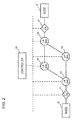
- FIG. 2 is a diagram showing a configuration of a communication system according to the first exemplary embodiment of the present invention.
- a configuration is shown that includes: layer 4 switches (referred to below as “L4SW(s)”) 21 to 24 that process packets in accordance with a flow entry set by a controller 31, layer 7 switches (referred to below as “L7SW(s)”) 41 and 42 that are disposed at two ends (entry and exit) of the L4SWs 21 to 24, and a controller 31 that controls the L4SW and the L7SW.
- L4SW(s) layer 4 switches
- L7SW(s) layer 7 switches 41 and 42 that are disposed at two ends (entry and exit) of the L4SWs 21 to 24, and a controller 31 that controls the L4SW and the L7SW.
- a solid line indicates a connection relationship with a network that transmits data between nodes 11 and 12, and a broken line represents a control channel between the controller 31 and the L4SW and L7SW.
- Nodes 11 and 12 indicate a user terminal or server or the like, which communicates via the communication system described above.
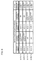
- the controller 31 has functionality equivalent to an OpenFlow controller of Non Patent Literature 1 and 2, and records flow entries (refer to FIG. 9 ) as control information with regard to the L4SWs 21 to 24.
- the controller 31 sets a header conversion table as shown in FIG. 5 to FIG. 8 , for L7SWs 41 and 42, and controls operation thereof..
- the L4SWs 21 to 24 have functionality equivalent to an OpenFlow switch of Non Patent Literature 1 and 2, and perform collation of match conditions of flow entries shown in FIG. 9 with header information of received packets, to search for a flow entry having a match condition that matches the header information of the received packets.
- the L4SWs 21 to 24 send a message (Packet-In) requesting the controller 31 to set a flow entry.
- the L7SWs 41 and 42 identify an application running in a connected node from a layer 7 header or the like of a received packet, and refer to the header conversion table shown in FIG. 5 to FIG. 8 , to perform an operation of rewriting the L4 header.
- the L7SW 41 refers to the header conversion table shown in FIG. 5 , and performs an operation of rewriting an L4 port number (60-1) of node 11 to 61-1.
- This type of L7SWs 41 and 42 can be implemented by a server having a function of relaying node communication, such as a proxy server, or a reverse proxy server. A description of specific functions of the L7SWs 41 and 42 is given later, along with operations thereof.
- L7SWs 41 and 42 and the controller 31 may be implemented on a computer configuring these apparatuses, by a computer program that executes the respective processes described above using hardware thereof.
- the controller 31 that receives the recording of the path selection policy from the user controls the L7SWs 41 and 42 as follows. First, the controller 31 determines a method of embedding path information in packets transmitted and received by the nodes 11 and 12.
- the method of embedding the path information is for any field in an L4 header or lower, to which the L2SW 21 to 24 refer.
- path information is embedded in an L4 port number on the node 11 side. That is, a packet from source node 11 addressed to node 12 embeds path information in a source L4 port number, and a frame from source node 12 addressed to node 11 embeds path information in a destination L4 port number.
- the controller 31 determines an L4 port number associated with the path described above.
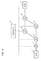
- a mapping is determined such that the L4 port number on the node 11 side of a packet flowing in path 51 is L4 port number 61, and the L4 port number on the node 11 side of the frame flowing in path 52 is L4 port number 62.
- These mapped port numbers are included in match conditions of a flow entry in the L4SWs 21 to 24 as path selection keys.
- L4 port numbers 61 and 62 mapped to paths 51 and 52 are rewritten to L4 port number 60 by the L7SW 42, and from node 12, L4 port number 60 is shown.
- L4 port number ranges 60, 61, 62 L4 port number ranges 60, 61, 62.
- the L4 port number ranges 61 and 62 must not overlap.
- the L4 port number range 60 may be the same as the L4 port number ranges 61 and 62.
- the L4 port number ranges 60, 61 and 62 each have port numbers associated, with the same size. Among the respective L4 port number ranges, an association is made among L4 port numbers 60-1, 61-1 and 62-1.
- a mapping of the paths used by the above applications and path selection keys is as in FIG. 3 , and is held as a path management table in the controller 31.
- the controller 31 notifies the L7SW 41 of a method of distinguishing, from packet content, the start of communication of application A and the start of communication of application B.
- the method of distinguishing the start of communication is based, for example, on information indicated by URL (Uniform Resource Locator) or XML (eXtensible Markup Language) content tag(s) in HTTP protocol.
- URL Uniform Resource Locator
- XML eXtensible Markup Language
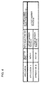
- the controller 31 records the header conversion table shown in FIG. 4 , associating communication of application A and the L4 port number range 61 on the node 11 side, and associating communication of application B and the L4 port number range 62 on the node 11 side.
- the recording in the header conversion table also provides notification to the L4 port number on the node 11 side, that the L4 port number ranges 61 and 62 are not to be used in communication outside of applications A and B. If there is a possibility of the L4 port number ranges 61 and 62 being used by node 11, the L7SW 41 may record an action to convert to another port number.
- Application of the header conversion table may be limited to communication between node 11 and node 12.
- the controller 31 records in the L7SW 42 a method of distinguishing an application from a packet, similar to the L7SW 41.
- the controller 31 records a header conversion table shown in FIG. 6 associating the L4 port number ranges 61 and 62 and the L4 port number range 60, in the L7SW 42. That is, with regard to the L4 port number ranges 61 and 62 on the node 11 side that have been converted by the L7SW 41, a conversion is performed so that the L4 port number range 60 is seen to be used from node 12.
- node 11 starts communication of application A addressed to L4 port number Y of node 12.
- Packets of application A are first delivered to L7SW 41 by node 11.
- the L7SW 41 since the L7SW 41 cannot distinguish an application until a three-way handshake is completed and L7 data is delivered, it is desirable that the L7SW 41 return a substitute response (SYN-ACK packet) to node 11 instead of node 12.
- SYN-ACK packet substitute response
- the three-way handshake itself may be handled by either application A or B, and delivery made to node 12.
- the L7SW 41 on recognizing that communication of application A has started, refers to a header rewrite table shown in FIG. 5 , and relays an L4 port number on the node 11 side in place of port number 61-1 selected from the L4 port number range 61.
- a packet relayed from the L7SW 41 addressed to node 12 is next delivered to the L4SW 21.
- the L4SW 21 searches for a flow entry having a match condition corresponding to the packet.
- the L4SW 21 sends a message (Packet-In) requesting setting of a flow entry accompanied by the packet, to the controller 31.
- the controller 31 Since a source L4 port number on the node 11 side, among header information included in the message (Packet-In), is within a range of the L4 port number range 61, the controller 31 recognizes that this is a communication of application A. From this recognition result, a flow entry is set for the L4SWs 21, 22 and 24 on path 51, so that the relevant packet flows in path 51. At this time, the L4 port number range 61 is set, as the L4 source port number, in a match condition of a flow entry set in the L4SW 21 forming a path branching point.
- FIG. 9 is an example of a flow entry set for the L4SW 21. At this point in time, entry 711 of FIG. 9 is set. It is to be noted that in the abovementioned description, the flow entry is set after waiting for the message (Packet-In) from the L4SW 21, but a flow entry may be set in advance in the L4SWs 21 to 24, at a time of setting the header rewrite table to the L7SWs 41 and 42.
- Packet-In Packet-In
- the controller 31 gives an instruction that a packet received from the L4SW 21 be transmitted to the L4SW 24, and transmitted in the direction of the L7SW 42 (Packet-Out message).
- the L7SW 42 refers to the header rewrite table shown in FIG. 6 , and recognizes that the source L4 port number of the packet forwarded from the L4SW 24 is the L4 port number 61-1, and due to being within the range of the L4 port number range 61, is a communication packet of application A.
- the L7SW 42 then refers to the header rewrite table shown in FIG. 6 and converts the source L4 port number to the L4 port number 60-1 that is a number corresponding to the L4 port number range 60, to be relayed to node 12.
- a packet that is finally delivered to node 12 is seen as being delivered from a port number of the L4 port number range 60 of node 11.
- node 12 returns a packet of application A to node 11.
- a packet of application A from node 12 addressed to node 11 to be delivered to the L7SW 42 has a destination port number of L4 port number 60-1, and is within the range of the L4 port number range 60.
- the L7SW 42 confirms that this packet is a packet of either of application A or B, in accordance with a method recorded by the controller 31. In a case where it is not possible to distinguish the application, a judgment is made that an application stored during the previous relay is still running.
- the L7SW 42 stores the fact that application A was run during the previous relay, judges that communication of application A is still continuing, rewrites an L4 port number that is a destination thereof to a corresponding L4 port number 61-1, and relays in the direction of the L4SW 24.
- the controller 31 After delivery to the L7SW 42, similar to packet forwarding in the direction of node 12 from node 11, based on a message (Packet-In) from the L4SW 24, the controller 31 creates a flow entry to cause packet forwarding along path 51 to be set in the L4SWs 24, 22 and 21, on path 51. The controller 31 instructs the L4SW 21 to perform packet forwarding in the direction of the L7SW 41.
- Packet-In Packet-In
- the L7SW 41 recognizes that communication of application A is continuing.
- the L7SW 41 refers to the header rewrite table shown in FIG. 5 , rewrites the destination L4 port number to port number (X) that node 11 is actually using, and relays to node 11.
- node 11 has started communication of application B with the same port number (X).
- the L7SW 41 when it relays a packet of application B from node 11, recognizes that this is a communication of application B.
- the L7SW 41 which recognizes that the L4 port used for application A is being used in application B, updates a field of a running application in the header rewrite table of FIG. 5 to "application B", as shown in FIG. 5 .
- the L7SW 41 refers to the header rewrite table of FIG. 7 , and rewrites an L4 source port number of a packet of application B to port number 62-1 of the L4 port number range 62, and relays in the direction of the L4SW 21.
- a TCP header sequence number is a number succeeding the previous packet, by only a port number change, rather than re-doing the TCP session.
- the L7SW 41 that receives the packet, similar to the case of application A, sends a message (Packet-In) requesting the controller 31 to set a flow entry accompanying the packet.
- the controller 31 sets a flow entry for application B in the L4SWs 21, 23 and 24 on path 52.
- the controller 31 gives an instruction to transmit a packet received from the L4SW 21 to the L4SW 24, and to transmit in the direction of the L7SW 42 (Packet-Out message).
- the L7SW 42 recognizes application B from a source L4 port number, and updates a field of a running application in the header rewrite table of FIG. 6 to "application B", as shown in FIG. 8 .
- the L7SW 42 refers to the header rewrite table of FIG. 8 , and converts an L4 source port number of a packet of application B to the port number 60-1, and relays to node 12.
- the source L4 port number after conversion is port number 60-1, the same as the port number used by application A, node 12 can recognize the communication as being in the same TCP session.
- a packet of application B in a case where a response packet is transmitted from node 12, the packet is transmitted to node 11 where a header rewrite is performed, similarly to the case of application A.
- apparatuses configuring a core network can be dedicated to forwarding. That is, a flow entry search function of a switch configuring the core network can be configured by an ASIC (Application Specific Integrated Circuit), so that speeding up can be expected.
- ASIC Application Specific Integrated Circuit
- switches outside of branching points for path selection need not be OpenFlow switches.
- the L4SWs 22 and 23 can learn MAC addresses to enable replacement by L2 switches that forward packets.
- a flow entry is set for each application. Therefore, by using a flow statistic function of an OpenFlow switch, and counting packets that match a flow entry, usage is also possible in a case such as that of measuring the communication amount of an application.
- FIG. 10 and FIG. 11 are diagrams representing configurations of a communication system according to the second exemplary embodiment of the invention. A description is given below, centered on points of difference from the first exemplary embodiment.
- FIG. 10 is a diagram representing a configuration of the second exemplary embodiment of the invention.
- FIG. 10 has a configuration in which an L7SW 42 is removed from the configuration of the first exemplary embodiment of FIG. 2 , and node 12 is connected to an L4SW 24.
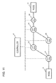
- FIG. 11 has a configuration in which an L7SW 41 is removed from the configuration of the first exemplary embodiment of FIG. 2 , and node 11 is connected to an L4SW 21.
- path control according to application is possible with regard to a packet from node 11 addressed to node 12.
- path control according to application is possible with regard to a packet from node 12 addressed to node 11.
- a flow entry is set to make an L4SW 24 perform further header rewriting of an L4 port number of a packet rewritten by an L7SW 41.
- a flow entry is set similarly to an L4SW 21.
- the L7SW refers to an L4 port number, and a detection is made that there has been a switch of application by an opposing node, but in the present exemplary embodiment this operation is not performed.
- FIG. 12 is a diagram representing a configuration of a communication system according to the third exemplary embodiment of the invention.
- the configuration of FIG. 12 is similar to FIG. 10 , but operations of an L7SW 43 are different.
- node 13 being an HTTP client
- node 14 being an HTTP server
- a description is given of the operations.
- Traffic of HTTP application C and HTTP application D is assumed to flow between node 13 and node 14 of a network in FIG. 12 . Therein, it is considered that communication of application C uses path 53 of FIG. 13 going through an L4SW 26, and communication of application D uses path 54 of FIG. 13 going through an L4 switch 27. A user records this path selection policy in a controller 32.
- the controller 32 that receives the recording of the path selection policy from the user controls an L7SW 43 as follows. First, the controller 32 records a method of distinguishing the start of communication of application C and the start of communication of application D, from the content of a packet to the L7SW 43. In a case of HTTP, it is possible to distinguish an application from the content of a request such as a URL or the like.
- the controller 32 records a header conversion table with attached actions, performing substitute connecting by a source L4 port number in a specific range, in the L7SW 43.
- FIG. 14 is an example of a header conversion table recorded in the L7SW 43.
- a range of the source L4 port number when a substitute connection for application C is made is L4 port number range 63
- a range of the source L4 port number when a substitute connection for application D is made is L4 port number range 64.
- the recording in the header conversion table also provides an instruction to the L7SW 43, that the L4 port number range 63 and the L4 port number range 64 are not to be used as source L4 port numbers in communication outside of with application C and application D.
- a packet transmitted by node 13 first reaches the L7SW 43.
- the L7SW 43 analyzes the packet, recognizes that node 13 has started communication of application C, and in accordance with entry 721 of FIG. 14 , performs a substitute connection to node 14, with source L4 port as L4 port 63-1 selected from the L4 port range 63.
- the controller 32 sets a flow entry to make L4SWs 25, 26 and 28 on path 53 forward a packet transmitted by the L7SW 43 that has a substitute connection to node 14, along path 53.
- a condition that the L4 port on the L7SW 43 side is within a range of the L4 port range 63 is set as a match condition.
- Node 14 recognizes a connection from the source L4 port 63-1.
- the controller 32 sets a flow entry that makes the L4SWs 25, 27 and 28 on the path 54 forward a packet transmitted by the L7SW 43 having a substitute connection to node 14, along path 54.
- a condition that the L4 port on the L7SW 43 side is within the range of the L4 port range 64 is set as a match condition.
- Node 14 recognizes a connection from source L4 port 64-2.
- L4SWs are used as lower layer switches, but other apparatuses that can operate as an OpenFlow switch are also possible.
- the communication system according to Mode 1 further including a second upper layer switch, disposed at another edge of the core network, which rewrites the header region of the lower layer rewritten by the upper layer switch, to prescribed content indicating a transmission source.
- the control apparatus instructs the upper layer switch or the second upper layer switch to convert a layer 4 port number of a received packet to a number range associated with application type.
- the communication system according to any one of Modes 1 to 7, wherein the lower layer switch is an OpenFlow switch, and the control apparatus is an OpenFlow controller that sets a flow entry that includes a layer 4 port number range in a match condition, as the control information.
- the lower layer switch is an OpenFlow switch
- the control apparatus is an OpenFlow controller that sets a flow entry that includes a layer 4 port number range in a match condition, as the control information.
- Modes 9 to 12 may be developed to Modes 2 to 8, similarly to Mode 1.
Landscapes
- Engineering & Computer Science (AREA)
- Computer Networks & Wireless Communication (AREA)
- Signal Processing (AREA)
- Computer Security & Cryptography (AREA)
- Data Exchanges In Wide-Area Networks (AREA)
Applications Claiming Priority (2)
| Application Number | Priority Date | Filing Date | Title |
|---|---|---|---|
| JP2012074654 | 2012-03-28 | ||
| PCT/JP2013/059008 WO2013146885A1 (fr) | 2012-03-28 | 2013-03-27 | Système de communication, commutateur de couche supérieure, dispositif de commande, procédé de commande de commutateur et programme |
Publications (3)
| Publication Number | Publication Date |
|---|---|
| EP2833585A1 true EP2833585A1 (fr) | 2015-02-04 |
| EP2833585A4 EP2833585A4 (fr) | 2015-10-21 |
| EP2833585B1 EP2833585B1 (fr) | 2017-03-08 |
Family
ID=49260134
Family Applications (1)
| Application Number | Title | Priority Date | Filing Date |
|---|---|---|---|
| EP13768798.4A Not-in-force EP2833585B1 (fr) | 2012-03-28 | 2013-03-27 | Système de communication, commutateur de couche supérieure, dispositif de commande, procédé de commande de commutateur et programme |
Country Status (5)
| Country | Link |
|---|---|
| US (1) | US9515926B2 (fr) |
| EP (1) | EP2833585B1 (fr) |
| JP (1) | JP5858147B2 (fr) |
| CN (1) | CN104205749B (fr) |
| WO (1) | WO2013146885A1 (fr) |
Cited By (1)
| Publication number | Priority date | Publication date | Assignee | Title |
|---|---|---|---|---|
| WO2017140367A1 (fr) * | 2016-02-18 | 2017-08-24 | Renesas Electronics Corporation | Gestionnaire de messages |
Families Citing this family (9)
| Publication number | Priority date | Publication date | Assignee | Title |
|---|---|---|---|---|
| JP3031604B2 (ja) | 1994-10-12 | 2000-04-10 | 旭サナック株式会社 | 塗装ロボットのスプレイガン自動交換装置 |
| TWI543566B (zh) | 2015-05-12 | 2016-07-21 | 財團法人工業技術研究院 | 基於軟體定義網路的資料中心網路系統及其封包傳送方法、位址解析方法與路由控制器 |
| JP6540283B2 (ja) * | 2015-06-30 | 2019-07-10 | 富士通株式会社 | 通信装置、通信方法、および、通信プログラム |
| CN113225238B (zh) | 2015-07-17 | 2022-08-26 | 华为技术有限公司 | 消息传输方法、接入节点、接入控制器及接入系统 |
| TWI636679B (zh) | 2017-02-07 | 2018-09-21 | 財團法人工業技術研究院 | 虛擬區域網路配置系統與方法及其電腦程式產品 |
| US10498658B2 (en) | 2017-10-23 | 2019-12-03 | Citrix Systems, Inc. | Systems and methods for first packet application classification |
| US20230013489A1 (en) * | 2021-07-16 | 2023-01-19 | Vmware, Inc. | Managing l4 ports |
| US12088555B2 (en) * | 2021-07-16 | 2024-09-10 | VMware LLC | Managing L4 ports |
| US12010095B2 (en) * | 2021-07-16 | 2024-06-11 | VMware LLC | Managing L4 ports |
Family Cites Families (13)
| Publication number | Priority date | Publication date | Assignee | Title |
|---|---|---|---|---|
| US7519048B2 (en) | 2000-12-28 | 2009-04-14 | Nec Corporation | Communication system and packet switching method thereof |
| JP3642305B2 (ja) | 2000-12-28 | 2005-04-27 | 日本電気株式会社 | 通信システムとそのパケット交換方法、及び交換プログラムを記録した記録媒体 |
| JP2004228791A (ja) | 2003-01-21 | 2004-08-12 | Hitachi Communication Technologies Ltd | バルク通信制御装置 |
| JP2005109536A (ja) | 2003-09-26 | 2005-04-21 | Nippon Telegr & Teleph Corp <Ntt> | アプリケーションフロー制御方法及びシステム |
| JP4398354B2 (ja) | 2004-12-20 | 2010-01-13 | 富士通株式会社 | 中継システム |
| US20060165053A1 (en) | 2005-01-21 | 2006-07-27 | Nec Laboratories America, Inc. | Content based data packet routing using labels |
| US7616563B1 (en) * | 2005-08-31 | 2009-11-10 | Chelsio Communications, Inc. | Method to implement an L4-L7 switch using split connections and an offloading NIC |
| US20080189769A1 (en) | 2007-02-01 | 2008-08-07 | Martin Casado | Secure network switching infrastructure |
| JP5477378B2 (ja) * | 2009-03-30 | 2014-04-23 | 日本電気株式会社 | 通信フロー制御システム、通信フロー制御方法及び通信フロー処理プログラム |
| JP5621778B2 (ja) | 2009-09-25 | 2014-11-12 | 日本電気株式会社 | コンテンツベーススイッチシステム、及びコンテンツベーススイッチ方法 |
| JP5382451B2 (ja) * | 2010-01-29 | 2014-01-08 | 日本電気株式会社 | フロントエンドシステム、フロントエンド処理方法 |
| EP2572473B1 (fr) * | 2010-05-19 | 2014-02-26 | Telefonaktiebolaget L M Ericsson (PUBL) | Procédés et appareil destinés à être utilisés dans un réseau openflow |
| JP5853378B2 (ja) * | 2011-03-04 | 2016-02-09 | 日本電気株式会社 | 通信切替システム、通信切替方法、及びプログラム |
-
2013
- 2013-03-27 US US14/388,206 patent/US9515926B2/en active Active
- 2013-03-27 WO PCT/JP2013/059008 patent/WO2013146885A1/fr not_active Ceased
- 2013-03-27 EP EP13768798.4A patent/EP2833585B1/fr not_active Not-in-force
- 2013-03-27 JP JP2014507958A patent/JP5858147B2/ja not_active Expired - Fee Related
- 2013-03-27 CN CN201380017101.3A patent/CN104205749B/zh not_active Expired - Fee Related
Cited By (5)
| Publication number | Priority date | Publication date | Assignee | Title |
|---|---|---|---|---|
| WO2017140367A1 (fr) * | 2016-02-18 | 2017-08-24 | Renesas Electronics Corporation | Gestionnaire de messages |
| US11019182B2 (en) | 2016-02-18 | 2021-05-25 | Renesas Electronics Corporation | Message handler |
| CN115086109A (zh) * | 2016-02-18 | 2022-09-20 | 瑞萨电子株式会社 | 消息处理器 |
| US11876879B2 (en) | 2016-02-18 | 2024-01-16 | Renesas Electronics Corporation | Message handler |
| US12212639B2 (en) | 2016-02-18 | 2025-01-28 | Renesas Electronics Corporation | Message handler |
Also Published As
| Publication number | Publication date |
|---|---|
| JPWO2013146885A1 (ja) | 2015-12-14 |
| WO2013146885A1 (fr) | 2013-10-03 |
| CN104205749B (zh) | 2017-04-05 |
| EP2833585B1 (fr) | 2017-03-08 |
| US20150043588A1 (en) | 2015-02-12 |
| EP2833585A4 (fr) | 2015-10-21 |
| US9515926B2 (en) | 2016-12-06 |
| CN104205749A (zh) | 2014-12-10 |
| JP5858147B2 (ja) | 2016-02-10 |
Similar Documents
| Publication | Publication Date | Title |
|---|---|---|
| EP2833585B1 (fr) | Système de communication, commutateur de couche supérieure, dispositif de commande, procédé de commande de commutateur et programme | |
| US8863269B2 (en) | Frontend system and frontend processing method | |
| EP2693708A1 (fr) | Système de réseau et procédé pour acquérir des données d'étiquette d'un réseau vlan | |
| US20130282867A1 (en) | Information system, control apparatus, method of providing virtual network, and program | |
| EP2814213A1 (fr) | Dispositif de commande, système de communication, procédé de communication et programme | |
| US20140241368A1 (en) | Control apparatus for forwarding apparatus, control method for forwarding apparatus, communication system, and program | |
| JPWO2011037105A1 (ja) | コンテンツベーススイッチシステム、及びコンテンツベーススイッチ方法 | |
| US10623278B2 (en) | Reactive mechanism for in-situ operation, administration, and maintenance traffic | |
| JP5858141B2 (ja) | 制御装置、通信装置、通信システム、通信方法及びプログラム | |
| EP2963869A1 (fr) | Système de communication, commutateur, appareil de commande, procédé et programme de configuration de canal de commande | |
| KR20160122226A (ko) | 통신 시스템, 제어 장치, 통신 제어 방법 및 프로그램 | |
| JP5720340B2 (ja) | 制御サーバ、通信システム、制御方法およびプログラム | |
| JP5725236B2 (ja) | 通信システム、ノード、パケット転送方法およびプログラム | |
| US20150256455A1 (en) | Communication system, path information exchange apparatus, communication node, forwarding method for path information and program | |
| CN107431658A (zh) | 通信系统、控制设备、控制方法及程序 | |
| US9942823B2 (en) | Communication terminal, communication method, and communication program | |
| CN104702505B (zh) | 一种报文传输方法和节点 | |
| JP2017050708A (ja) | 通信システム、制御装置、スイッチ、通信方法及びプログラム | |
| US10298454B2 (en) | Communication path switching apparatus, method for controlling communication path switching apparatus, and computer program product | |
| JP2015521391A (ja) | 通信システムと通信方法並びにプログラム | |
| US20160301629A1 (en) | Control device, network system, packet transfer control method, and program for control device | |
| CN106067864B (zh) | 一种报文处理方法及装置 | |
| JP2016225933A (ja) | 制御装置、中継装置の制御方法、プログラム及び通信システム | |
| WO2015129727A1 (fr) | Terminal de communications, procédé de communications et programme | |
| WO2015118811A1 (fr) | Système de communication, dispositif d'acheminement de paquet, procédé d'acheminement de paquet et programme d'acheminement de paquet |
Legal Events
| Date | Code | Title | Description |
|---|---|---|---|
| PUAI | Public reference made under article 153(3) epc to a published international application that has entered the european phase |
Free format text: ORIGINAL CODE: 0009012 |
|
| 17P | Request for examination filed |
Effective date: 20141003 |
|
| AK | Designated contracting states |
Kind code of ref document: A1 Designated state(s): AL AT BE BG CH CY CZ DE DK EE ES FI FR GB GR HR HU IE IS IT LI LT LU LV MC MK MT NL NO PL PT RO RS SE SI SK SM TR |
|
| AX | Request for extension of the european patent |
Extension state: BA ME |
|
| DAX | Request for extension of the european patent (deleted) | ||
| RA4 | Supplementary search report drawn up and despatched (corrected) |
Effective date: 20150923 |
|
| RIC1 | Information provided on ipc code assigned before grant |
Ipc: H04L 12/859 20130101ALI20150917BHEP Ipc: H04L 12/801 20130101ALI20150917BHEP Ipc: H04L 12/717 20130101AFI20150917BHEP Ipc: H04L 12/715 20130101ALI20150917BHEP |
|
| GRAP | Despatch of communication of intention to grant a patent |
Free format text: ORIGINAL CODE: EPIDOSNIGR1 |
|
| RIC1 | Information provided on ipc code assigned before grant |
Ipc: H04L 12/801 20130101ALI20160816BHEP Ipc: H04L 12/715 20130101ALI20160816BHEP Ipc: H04L 12/717 20130101AFI20160816BHEP Ipc: H04L 12/859 20130101ALI20160816BHEP |
|
| INTG | Intention to grant announced |
Effective date: 20160916 |
|
| GRAS | Grant fee paid |
Free format text: ORIGINAL CODE: EPIDOSNIGR3 |
|
| GRAA | (expected) grant |
Free format text: ORIGINAL CODE: 0009210 |
|
| AK | Designated contracting states |
Kind code of ref document: B1 Designated state(s): AL AT BE BG CH CY CZ DE DK EE ES FI FR GB GR HR HU IE IS IT LI LT LU LV MC MK MT NL NO PL PT RO RS SE SI SK SM TR |
|
| REG | Reference to a national code |
Ref country code: GB Ref legal event code: FG4D |
|
| REG | Reference to a national code |
Ref country code: CH Ref legal event code: EP Ref country code: AT Ref legal event code: REF Ref document number: 874429 Country of ref document: AT Kind code of ref document: T Effective date: 20170315 |
|
| REG | Reference to a national code |
Ref country code: IE Ref legal event code: FG4D |
|
| REG | Reference to a national code |
Ref country code: FR Ref legal event code: PLFP Year of fee payment: 5 |
|
| REG | Reference to a national code |
Ref country code: DE Ref legal event code: R096 Ref document number: 602013018332 Country of ref document: DE |
|
| REG | Reference to a national code |
Ref country code: LT Ref legal event code: MG4D |
|
| REG | Reference to a national code |
Ref country code: NL Ref legal event code: MP Effective date: 20170308 |
|
| PG25 | Lapsed in a contracting state [announced via postgrant information from national office to epo] |
Ref country code: NO Free format text: LAPSE BECAUSE OF FAILURE TO SUBMIT A TRANSLATION OF THE DESCRIPTION OR TO PAY THE FEE WITHIN THE PRESCRIBED TIME-LIMIT Effective date: 20170608 Ref country code: GR Free format text: LAPSE BECAUSE OF FAILURE TO SUBMIT A TRANSLATION OF THE DESCRIPTION OR TO PAY THE FEE WITHIN THE PRESCRIBED TIME-LIMIT Effective date: 20170609 Ref country code: LT Free format text: LAPSE BECAUSE OF FAILURE TO SUBMIT A TRANSLATION OF THE DESCRIPTION OR TO PAY THE FEE WITHIN THE PRESCRIBED TIME-LIMIT Effective date: 20170308 Ref country code: HR Free format text: LAPSE BECAUSE OF FAILURE TO SUBMIT A TRANSLATION OF THE DESCRIPTION OR TO PAY THE FEE WITHIN THE PRESCRIBED TIME-LIMIT Effective date: 20170308 Ref country code: FI Free format text: LAPSE BECAUSE OF FAILURE TO SUBMIT A TRANSLATION OF THE DESCRIPTION OR TO PAY THE FEE WITHIN THE PRESCRIBED TIME-LIMIT Effective date: 20170308 |
|
| REG | Reference to a national code |
Ref country code: AT Ref legal event code: MK05 Ref document number: 874429 Country of ref document: AT Kind code of ref document: T Effective date: 20170308 |
|
| PG25 | Lapsed in a contracting state [announced via postgrant information from national office to epo] |
Ref country code: BG Free format text: LAPSE BECAUSE OF FAILURE TO SUBMIT A TRANSLATION OF THE DESCRIPTION OR TO PAY THE FEE WITHIN THE PRESCRIBED TIME-LIMIT Effective date: 20170608 Ref country code: LV Free format text: LAPSE BECAUSE OF FAILURE TO SUBMIT A TRANSLATION OF THE DESCRIPTION OR TO PAY THE FEE WITHIN THE PRESCRIBED TIME-LIMIT Effective date: 20170308 Ref country code: SE Free format text: LAPSE BECAUSE OF FAILURE TO SUBMIT A TRANSLATION OF THE DESCRIPTION OR TO PAY THE FEE WITHIN THE PRESCRIBED TIME-LIMIT Effective date: 20170308 Ref country code: ES Free format text: LAPSE BECAUSE OF FAILURE TO SUBMIT A TRANSLATION OF THE DESCRIPTION OR TO PAY THE FEE WITHIN THE PRESCRIBED TIME-LIMIT Effective date: 20170308 Ref country code: RS Free format text: LAPSE BECAUSE OF FAILURE TO SUBMIT A TRANSLATION OF THE DESCRIPTION OR TO PAY THE FEE WITHIN THE PRESCRIBED TIME-LIMIT Effective date: 20170308 |
|
| PG25 | Lapsed in a contracting state [announced via postgrant information from national office to epo] |
Ref country code: NL Free format text: LAPSE BECAUSE OF FAILURE TO SUBMIT A TRANSLATION OF THE DESCRIPTION OR TO PAY THE FEE WITHIN THE PRESCRIBED TIME-LIMIT Effective date: 20170308 |
|
| PG25 | Lapsed in a contracting state [announced via postgrant information from national office to epo] |
Ref country code: EE Free format text: LAPSE BECAUSE OF FAILURE TO SUBMIT A TRANSLATION OF THE DESCRIPTION OR TO PAY THE FEE WITHIN THE PRESCRIBED TIME-LIMIT Effective date: 20170308 Ref country code: RO Free format text: LAPSE BECAUSE OF FAILURE TO SUBMIT A TRANSLATION OF THE DESCRIPTION OR TO PAY THE FEE WITHIN THE PRESCRIBED TIME-LIMIT Effective date: 20170308 Ref country code: AT Free format text: LAPSE BECAUSE OF FAILURE TO SUBMIT A TRANSLATION OF THE DESCRIPTION OR TO PAY THE FEE WITHIN THE PRESCRIBED TIME-LIMIT Effective date: 20170308 Ref country code: IT Free format text: LAPSE BECAUSE OF FAILURE TO SUBMIT A TRANSLATION OF THE DESCRIPTION OR TO PAY THE FEE WITHIN THE PRESCRIBED TIME-LIMIT Effective date: 20170308 Ref country code: SK Free format text: LAPSE BECAUSE OF FAILURE TO SUBMIT A TRANSLATION OF THE DESCRIPTION OR TO PAY THE FEE WITHIN THE PRESCRIBED TIME-LIMIT Effective date: 20170308 Ref country code: CZ Free format text: LAPSE BECAUSE OF FAILURE TO SUBMIT A TRANSLATION OF THE DESCRIPTION OR TO PAY THE FEE WITHIN THE PRESCRIBED TIME-LIMIT Effective date: 20170308 |
|
| REG | Reference to a national code |
Ref country code: CH Ref legal event code: PL |
|
| PG25 | Lapsed in a contracting state [announced via postgrant information from national office to epo] |
Ref country code: PL Free format text: LAPSE BECAUSE OF FAILURE TO SUBMIT A TRANSLATION OF THE DESCRIPTION OR TO PAY THE FEE WITHIN THE PRESCRIBED TIME-LIMIT Effective date: 20170308 Ref country code: IS Free format text: LAPSE BECAUSE OF FAILURE TO SUBMIT A TRANSLATION OF THE DESCRIPTION OR TO PAY THE FEE WITHIN THE PRESCRIBED TIME-LIMIT Effective date: 20170708 Ref country code: SM Free format text: LAPSE BECAUSE OF FAILURE TO SUBMIT A TRANSLATION OF THE DESCRIPTION OR TO PAY THE FEE WITHIN THE PRESCRIBED TIME-LIMIT Effective date: 20170308 Ref country code: PT Free format text: LAPSE BECAUSE OF FAILURE TO SUBMIT A TRANSLATION OF THE DESCRIPTION OR TO PAY THE FEE WITHIN THE PRESCRIBED TIME-LIMIT Effective date: 20170710 |
|
| REG | Reference to a national code |
Ref country code: DE Ref legal event code: R097 Ref document number: 602013018332 Country of ref document: DE |
|
| REG | Reference to a national code |
Ref country code: IE Ref legal event code: MM4A |
|
| PLBE | No opposition filed within time limit |
Free format text: ORIGINAL CODE: 0009261 |
|
| STAA | Information on the status of an ep patent application or granted ep patent |
Free format text: STATUS: NO OPPOSITION FILED WITHIN TIME LIMIT |
|
| PG25 | Lapsed in a contracting state [announced via postgrant information from national office to epo] |
Ref country code: MC Free format text: LAPSE BECAUSE OF FAILURE TO SUBMIT A TRANSLATION OF THE DESCRIPTION OR TO PAY THE FEE WITHIN THE PRESCRIBED TIME-LIMIT Effective date: 20170308 Ref country code: DK Free format text: LAPSE BECAUSE OF FAILURE TO SUBMIT A TRANSLATION OF THE DESCRIPTION OR TO PAY THE FEE WITHIN THE PRESCRIBED TIME-LIMIT Effective date: 20170308 Ref country code: LU Free format text: LAPSE BECAUSE OF NON-PAYMENT OF DUE FEES Effective date: 20170327 |
|
| 26N | No opposition filed |
Effective date: 20171211 |
|
| REG | Reference to a national code |
Ref country code: FR Ref legal event code: PLFP Year of fee payment: 6 |
|
| PG25 | Lapsed in a contracting state [announced via postgrant information from national office to epo] |
Ref country code: CH Free format text: LAPSE BECAUSE OF NON-PAYMENT OF DUE FEES Effective date: 20170331 Ref country code: SI Free format text: LAPSE BECAUSE OF FAILURE TO SUBMIT A TRANSLATION OF THE DESCRIPTION OR TO PAY THE FEE WITHIN THE PRESCRIBED TIME-LIMIT Effective date: 20170308 Ref country code: LI Free format text: LAPSE BECAUSE OF NON-PAYMENT OF DUE FEES Effective date: 20170331 Ref country code: IE Free format text: LAPSE BECAUSE OF NON-PAYMENT OF DUE FEES Effective date: 20170327 |
|
| REG | Reference to a national code |
Ref country code: BE Ref legal event code: MM Effective date: 20170331 |
|
| PG25 | Lapsed in a contracting state [announced via postgrant information from national office to epo] |
Ref country code: BE Free format text: LAPSE BECAUSE OF NON-PAYMENT OF DUE FEES Effective date: 20170331 |
|
| PG25 | Lapsed in a contracting state [announced via postgrant information from national office to epo] |
Ref country code: MT Free format text: LAPSE BECAUSE OF NON-PAYMENT OF DUE FEES Effective date: 20170327 |
|
| PG25 | Lapsed in a contracting state [announced via postgrant information from national office to epo] |
Ref country code: HU Free format text: LAPSE BECAUSE OF FAILURE TO SUBMIT A TRANSLATION OF THE DESCRIPTION OR TO PAY THE FEE WITHIN THE PRESCRIBED TIME-LIMIT; INVALID AB INITIO Effective date: 20130327 |
|
| PG25 | Lapsed in a contracting state [announced via postgrant information from national office to epo] |
Ref country code: CY Free format text: LAPSE BECAUSE OF FAILURE TO SUBMIT A TRANSLATION OF THE DESCRIPTION OR TO PAY THE FEE WITHIN THE PRESCRIBED TIME-LIMIT Effective date: 20170308 |
|
| PG25 | Lapsed in a contracting state [announced via postgrant information from national office to epo] |
Ref country code: MK Free format text: LAPSE BECAUSE OF FAILURE TO SUBMIT A TRANSLATION OF THE DESCRIPTION OR TO PAY THE FEE WITHIN THE PRESCRIBED TIME-LIMIT Effective date: 20170308 |
|
| PG25 | Lapsed in a contracting state [announced via postgrant information from national office to epo] |
Ref country code: TR Free format text: LAPSE BECAUSE OF FAILURE TO SUBMIT A TRANSLATION OF THE DESCRIPTION OR TO PAY THE FEE WITHIN THE PRESCRIBED TIME-LIMIT Effective date: 20170308 |
|
| PG25 | Lapsed in a contracting state [announced via postgrant information from national office to epo] |
Ref country code: AL Free format text: LAPSE BECAUSE OF FAILURE TO SUBMIT A TRANSLATION OF THE DESCRIPTION OR TO PAY THE FEE WITHIN THE PRESCRIBED TIME-LIMIT Effective date: 20170308 |
|
| PGFP | Annual fee paid to national office [announced via postgrant information from national office to epo] |
Ref country code: FR Payment date: 20210210 Year of fee payment: 9 |
|
| PGFP | Annual fee paid to national office [announced via postgrant information from national office to epo] |
Ref country code: DE Payment date: 20210316 Year of fee payment: 9 Ref country code: GB Payment date: 20210318 Year of fee payment: 9 |
|
| REG | Reference to a national code |
Ref country code: DE Ref legal event code: R079 Ref document number: 602013018332 Country of ref document: DE Free format text: PREVIOUS MAIN CLASS: H04L0012717000 Ipc: H04L0045420000 |
|
| REG | Reference to a national code |
Ref country code: DE Ref legal event code: R119 Ref document number: 602013018332 Country of ref document: DE |
|
| GBPC | Gb: european patent ceased through non-payment of renewal fee |
Effective date: 20220327 |
|
| PG25 | Lapsed in a contracting state [announced via postgrant information from national office to epo] |
Ref country code: GB Free format text: LAPSE BECAUSE OF NON-PAYMENT OF DUE FEES Effective date: 20220327 Ref country code: FR Free format text: LAPSE BECAUSE OF NON-PAYMENT OF DUE FEES Effective date: 20220331 Ref country code: DE Free format text: LAPSE BECAUSE OF NON-PAYMENT OF DUE FEES Effective date: 20221001 |