EP2833596A1 - Procédé et dispositif pour partager un disposiitif dlna - Google Patents
Procédé et dispositif pour partager un disposiitif dlna Download PDFInfo
- Publication number
- EP2833596A1 EP2833596A1 EP13796843.4A EP13796843A EP2833596A1 EP 2833596 A1 EP2833596 A1 EP 2833596A1 EP 13796843 A EP13796843 A EP 13796843A EP 2833596 A1 EP2833596 A1 EP 2833596A1
- Authority
- EP
- European Patent Office
- Prior art keywords
- dlna
- network
- gateway
- virtual
- data channel
- Prior art date
- Legal status (The legal status is an assumption and is not a legal conclusion. Google has not performed a legal analysis and makes no representation as to the accuracy of the status listed.)
- Granted
Links
Images



Classifications
-
- H—ELECTRICITY
- H04—ELECTRIC COMMUNICATION TECHNIQUE
- H04L—TRANSMISSION OF DIGITAL INFORMATION, e.g. TELEGRAPHIC COMMUNICATION
- H04L65/00—Network arrangements, protocols or services for supporting real-time applications in data packet communication
- H04L65/1066—Session management
- H04L65/1069—Session establishment or de-establishment
-
- H—ELECTRICITY
- H04—ELECTRIC COMMUNICATION TECHNIQUE
- H04L—TRANSMISSION OF DIGITAL INFORMATION, e.g. TELEGRAPHIC COMMUNICATION
- H04L67/00—Network arrangements or protocols for supporting network services or applications
- H04L67/01—Protocols
- H04L67/12—Protocols specially adapted for proprietary or special-purpose networking environments, e.g. medical networks, sensor networks, networks in vehicles or remote metering networks
- H04L67/125—Protocols specially adapted for proprietary or special-purpose networking environments, e.g. medical networks, sensor networks, networks in vehicles or remote metering networks involving control of end-device applications over a network
-
- H—ELECTRICITY
- H04—ELECTRIC COMMUNICATION TECHNIQUE
- H04L—TRANSMISSION OF DIGITAL INFORMATION, e.g. TELEGRAPHIC COMMUNICATION
- H04L12/00—Data switching networks
- H04L12/28—Data switching networks characterised by path configuration, e.g. LAN [Local Area Networks] or WAN [Wide Area Networks]
- H04L12/2803—Home automation networks
- H04L12/2816—Controlling appliance services of a home automation network by calling their functionalities
- H04L12/2818—Controlling appliance services of a home automation network by calling their functionalities from a device located outside both the home and the home network
-
- H—ELECTRICITY
- H04—ELECTRIC COMMUNICATION TECHNIQUE
- H04L—TRANSMISSION OF DIGITAL INFORMATION, e.g. TELEGRAPHIC COMMUNICATION
- H04L12/00—Data switching networks
- H04L12/28—Data switching networks characterised by path configuration, e.g. LAN [Local Area Networks] or WAN [Wide Area Networks]
- H04L12/2803—Home automation networks
- H04L12/283—Processing of data at an internetworking point of a home automation network
- H04L12/2832—Interconnection of the control functionalities between home networks
-
- H—ELECTRICITY
- H04—ELECTRIC COMMUNICATION TECHNIQUE
- H04L—TRANSMISSION OF DIGITAL INFORMATION, e.g. TELEGRAPHIC COMMUNICATION
- H04L12/00—Data switching networks
- H04L12/28—Data switching networks characterised by path configuration, e.g. LAN [Local Area Networks] or WAN [Wide Area Networks]
- H04L12/46—Interconnection of networks
- H04L12/4604—LAN interconnection over a backbone network, e.g. Internet, Frame Relay
-
- H—ELECTRICITY
- H04—ELECTRIC COMMUNICATION TECHNIQUE
- H04L—TRANSMISSION OF DIGITAL INFORMATION, e.g. TELEGRAPHIC COMMUNICATION
- H04L65/00—Network arrangements, protocols or services for supporting real-time applications in data packet communication
- H04L65/10—Architectures or entities
- H04L65/102—Gateways
- H04L65/1023—Media gateways
-
- H—ELECTRICITY
- H04—ELECTRIC COMMUNICATION TECHNIQUE
- H04L—TRANSMISSION OF DIGITAL INFORMATION, e.g. TELEGRAPHIC COMMUNICATION
- H04L67/00—Network arrangements or protocols for supporting network services or applications
- H04L67/01—Protocols
- H04L67/02—Protocols based on web technology, e.g. hypertext transfer protocol [HTTP]
-
- H—ELECTRICITY
- H04—ELECTRIC COMMUNICATION TECHNIQUE
- H04L—TRANSMISSION OF DIGITAL INFORMATION, e.g. TELEGRAPHIC COMMUNICATION
- H04L67/00—Network arrangements or protocols for supporting network services or applications
- H04L67/01—Protocols
- H04L67/04—Protocols specially adapted for terminals or networks with limited capabilities; specially adapted for terminal portability
-
- H—ELECTRICITY
- H04—ELECTRIC COMMUNICATION TECHNIQUE
- H04L—TRANSMISSION OF DIGITAL INFORMATION, e.g. TELEGRAPHIC COMMUNICATION
- H04L67/00—Network arrangements or protocols for supporting network services or applications
- H04L67/01—Protocols
- H04L67/08—Protocols specially adapted for terminal emulation, e.g. Telnet
-
- H—ELECTRICITY
- H04—ELECTRIC COMMUNICATION TECHNIQUE
- H04L—TRANSMISSION OF DIGITAL INFORMATION, e.g. TELEGRAPHIC COMMUNICATION
- H04L67/00—Network arrangements or protocols for supporting network services or applications
- H04L67/2866—Architectures; Arrangements
- H04L67/2876—Pairs of inter-processing entities at each side of the network, e.g. split proxies
-
- H—ELECTRICITY
- H04—ELECTRIC COMMUNICATION TECHNIQUE
- H04L—TRANSMISSION OF DIGITAL INFORMATION, e.g. TELEGRAPHIC COMMUNICATION
- H04L67/00—Network arrangements or protocols for supporting network services or applications
- H04L67/50—Network services
- H04L67/51—Discovery or management thereof, e.g. service location protocol [SLP] or web services
-
- H—ELECTRICITY
- H04—ELECTRIC COMMUNICATION TECHNIQUE
- H04L—TRANSMISSION OF DIGITAL INFORMATION, e.g. TELEGRAPHIC COMMUNICATION
- H04L67/00—Network arrangements or protocols for supporting network services or applications
- H04L67/50—Network services
- H04L67/56—Provisioning of proxy services
- H04L67/59—Providing operational support to end devices by off-loading in the network or by emulation, e.g. when they are unavailable
Definitions
- the present invention relates to the field of communications, and in particular, to a method and apparatus for sharing a Digital Living Network Alliance (DLNA for short) device.
- DLNA Digital Living Network Alliance
- the Digital Living Network Alliance (DLNA for short) is a nonprofit organization initiated by SONY, Intel and Microsoft, and aims to solve the sharing of digital media contents between consumer electronic devices.
- the DLNA uses a Universal Plug and Play (UPnP for short) protocol to discover, describe and control devices.
- UPS Universal Plug and Play
- various roles of the DLNA device are defined: a Digital Media Server (DMS for short), a Digital Media Player (DMP for short), a Digital Media Controller (DMC for short), and a Digital Media Renderer (DMR for short).
- DMS Digital Media Server
- DMP Digital Media Player
- DMC Digital Media Controller
- DMR Digital Media Renderer
- the DMS and DMR may broadcast its own online information and description information to the network through a Simple Service Discovery Protocol (SSDP for short), so as to enable the DMC to play the media contents shared by the DMS on the DMR or enable the DMP to play the media contents shared on the DMS.
- the communication protocol therebetween may be a HyperText Transfer Protocol (HTTP for short), and may be carried by using a User Datagram Protocol (UDP for short) or a Transmission Control Protocol (TCP for short), for example, the SSDP uses HTTP over UDP, and HTTP over TCP is used to acquire the device description information and service description information as well as subsequent device control.
- HTTP HyperText Transfer Protocol
- UDP User Datagram Protocol
- TCP Transmission Control Protocol
- the DLNA network generally is a local area network environment in a home environment, or an operating network or public network of the same subnet, and the method for sharing media resources of the DLNA can not be used currently for the wide area network or a network of different subnets. Therefore, the DLNA sharing is only limited in a local range, it is not expanded to sharing on the internet, and it can not be more widely applied.
- the embodiments of the present invention provide a method and apparatus for sharing a DLNA device, to solve the problem in the related technologies that the DLNA sharing is only limited in a local range.
- a method for sharing a Digital Living Network Alliance (DLNA) device comprising: establishing a data channel between a first DLNA gateway in a first DLNA network and a second DLNA gateway in a second DLNA network, wherein the DLNA gateway is a DLNA device having a DMC function and capable of accessing the Internet; adding, in the second DLNA gateway, a virtual DLNA device corresponding to a DLNA device in the first DLNA network; and a DLNA device in the second DLNA network performing remote control and/or remote play for the DLNA device in the first DLNA network through the virtual DLNA device.
- DLNA Digital Living Network Alliance
- the step of a DLNA device in the second DLNA network performing remote control and/or remote play for the DLNA device in the first DLNA network through the virtual DLNA device comprises: in a case that the DLNA device in the second DLNA network controls the virtual DLNA device, the second DLNA gateway controlling the virtual DLNA device through the data channel; and/or in a case that the DLNA device in the second DLNA network plays media resources in the virtual DLNA device, the second DLNA gateway acquiring the media resources of the DLNA device in the first DLNA network corresponding to the virtual DLNA device through the data channel and playing the media resources.
- the step of establishing a data channel between a first DLNA gateway in a first DLNA network and a second DLNA gateway in a second DLNA network comprises: establishing a data channel between the first DLNA gateway and the second DLNA gateway through an XMPP server.
- establishing a data channel between the first DLNA gateway and the second DLNA gateway through an XMPP server comprises: the first DLNA gateway and the second DLNA gateway logging in the XMPP server using the same account; and the first DLNA gateway and the second DLNA gateway establishing the data channel.
- the method further comprises: the first DLNA gateway and/or the second DLNA gateway logging out the account; and the second DLNA gateway broadcasting that the virtual DLNA device leaves the second DLNA network in the second DLNA network through an SSDP message.
- the step of adding, in the second DLNA gateway, a virtual DLNA device corresponding to a DLNA device in the first DLNA network comprises: the first DLNA gateway transmitting the SSDP message broadcasted by the DLNA device in the first DLNA network to the second DLNA gateway through the data channel; and the second DLNA gateway adding the virtual DLNA device corresponding to the DLNA device, amending the SSDP message broadcast by the DLNA device in the first DLNA network, and broadcasting the amended SSDP message in the second DLNA network.
- the SSDP message broadcasted by the DLNA device in the first DLNA network comprises a first URL within the first DLNA network of the DLNA device in the first DLNA network
- the second DLNA gateway broadcasting the amended SSDP message in the second DLNA network comprises: the second DLNA gateway amending the first URL in the SSDP message to a second URL within the second DLNA network of the second DLNA gateway as a URL of the virtual DLNA device, and broadcasting the amended SSDP message in the second DLNA network.
- the data channel is a UDP based data channel.
- the step of the DLNA device in the second DLNA network performing remote control and/or remote play for the DLNA device in the first DLNA network through the virtual DLNA device comprises: the second DLNA gateway transforming a message for remote control and/or remote play transmitted by the DLNA device in the second DLNA network to the virtual DLNA device from an HTTP format into an UDP format, and transmitting the transformed message to the first DLNA gateway through the data channel; and the second DLNA gateway transforming a response message corresponding to the message returned by the first DLNA gateway from the UDP format into the HTTP format, and forwarding the transformed response message to the DLNA device performing remote control and/or remote play.
- an apparatus for sharing a DLNA device located in a second DLNA gateway of a second DLNA network comprising: an establishment module, configured to establish a data channel with a first DLNA gateway in a first DLNA network, wherein the DLNA gateway is a DLNA device having a DMC function and capable of accessing the Internet; a processing module, configured to add a virtual DLNA device corresponding to a DLNA device in the first DLNA network; and a remote operating module, configured to operate, by the DLNA device in the second DLNA network, to perform remote control and/or remote play for the DLNA device in the first DLNA network through the virtual DLNA device.
- the remote operating module comprises: a remote control unit, configured to control the virtual DLNA device through the data channel in a case that the DLNA device in the second DLNA network controls the virtual DLNA device; and/or a remote play unit, configured to acquire the media resources of the DLNA device in the first DLNA network corresponding to the virtual DLNA device through the data channel and play the media resources in a case that the DLNA device in the second DLNA network plays media resources in the virtual DLNA device.
- a remote control unit configured to control the virtual DLNA device through the data channel in a case that the DLNA device in the second DLNA network controls the virtual DLNA device
- a remote play unit configured to acquire the media resources of the DLNA device in the first DLNA network corresponding to the virtual DLNA device through the data channel and play the media resources in a case that the DLNA device in the second DLNA network plays media resources in the virtual DLNA device.
- the establishment module comprises: a login unit, configured to log in an XMPP server using the same account as that of the first DLNA gateway; and an establishment unit, configured to establish the data channel with the first DLNA gateway.
- the apparatus further comprises: a logout module, configured to log out the account; and a broadcast module, configured to broadcast that the virtual DLNA device leaves the second DLNA network in the second DLNA network through an SSDP message.
- a logout module configured to log out the account
- a broadcast module configured to broadcast that the virtual DLNA device leaves the second DLNA network in the second DLNA network through an SSDP message.
- the processing module comprises: a reception module, configured to receive the SSDP message broadcasted by the DLNA device in the first DLNA network transmitted by the first DLNA gateway through the data channel; an adding module, configured to add the virtual DLNA device corresponding to the DLNA device; and a first transformation module, configured to amend the first URL in the SSDP message to a second URL within the second DLNA network of the second DLNA gateway as a URL of the virtual DLNA device, and broadcast the amended SSDP message in the second DLNA network in a case that the SSDP message comprises a first URL within the first DLNA network of the DLNA device in the first DLNA network.
- the remote operating module comprises: a second transformation module, configured to transform a message for remote control and/or remote play transmitted by the DLNA device in the second DLNA network to the virtual DLNA device from an HTTP format into an UDP format, and transmit the transformed message to the first DLNA gateway through the data channel; and further configured to transform a response message corresponding to the message returned by the first DLNA gateway from the UDP format into the HTTP format, and forward the transformed response message to the DLNA device performing remote control and/or remote play.
- a second transformation module configured to transform a message for remote control and/or remote play transmitted by the DLNA device in the second DLNA network to the virtual DLNA device from an HTTP format into an UDP format, and transmit the transformed message to the first DLNA gateway through the data channel; and further configured to transform a response message corresponding to the message returned by the first DLNA gateway from the UDP format into the HTTP format, and forward the transformed response message to the DLNA device performing remote control and/or remote play.
- a data channel is established between a first DLNA gateway in a first DLNA network and a second DLNA gateway in a second DLNA network, wherein the DLNA gateway is a DLNA device having a DMC function and capable of accessing the Internet; a virtual DLNA device corresponding to a DLNA device in the first DLNA network is added in the second DLNA gateway; and a DLNA device in the second DLNA network performs remote control and/or remote play for the DLNA device in the first DLNA network through the virtual DLNA device.
- FIG. 1 is a flowchart of a method for sharing a DLNA device according to an embodiment of the present invention. As shown in Fig. 1 , the method comprises the following steps:
- the DLNA device in the first DLNA network is presented in the second DLNA gateway by way of a virtual device, and the DLNA device in the second DLNA network performs remote control and/or remote play for the DLNA device in the first DLNA network through the virtual DLNA device, thereby implementing a remote operation on the DLNA device in the first DLNA network by the DLNA device in the second DLNA network.
- the access scheme of the DLNA device in the embodiments is not limited to being between two DLNA networks, and instead, the access of a DLNA device among multiple DLNA networks may also be implemented by the access scheme of a DLNA device in the embodiments.
- a DLNA device in the second DLNA network performing remote control and/or remote play for the DLNA device in the first DLNA network through the virtual DLNA device may be implemented by the following modes: in a case that the DLNA device in the second DLNA network controls the virtual DLNA device, the second DLNA gateway controlling the virtual DLNA device through the data channel; and in a case that the DLNA device in the second DLNA network plays media resources in the virtual DLNA device, the second DLNA gateway acquiring the media resources of the DLNA device in the first DLNA network corresponding to the virtual DLNA device through the data channel and playing the media resources.
- This mode is easy to operate and has a strong realizability.
- the data channel may be established by way of a third-party server.
- the data channel between the first DLNA gateway and the second DLNA gateway may be established through an XMPP server.
- the XMPP server will notify information that one gateway is online to the other gateway, for example, information that a latter login gateway is online may be notified to a former login gateway, facilitating both gateways negotiating to establish a data channel therebeween, and of course, it may also be substituted with an opposite notification order.
- the first DLNA gateway and the second DLNA gateway may negotiate through an XMPP protocol to establish the data channel.
- the data channel may be a UDP based data channel.
- the first DLNA gateway and the second DLNA gateway may be used as transformation devices to transform a message format between the DLNA gateway where it is located and the data channel.
- the second DLNA gateway may transform a message for remote control and/or remote play transmitted by the DLNA device in the second DLNA network to the virtual DLNA device from a HTTP format into an UDP format, and transmit the transformed message to the first DLNA gateway through the data channel; and the second DLNA gateway transforms a response message corresponding to the message returned by the first DLNA gateway from the UDP format into the HTTP format, and forwards the transformed response message to the DLNA device performing remote control and/or remote play.
- the connection may be disconnected by any one or both of the first DLNA gateway or the second DLNA gateway logging out the above account; and in such case, the DLNA gateway of the virtual DLNA device may broadcast that all virtual DLNA devices exit the DLNA network in the DLNA network where it is located through the SSDP message.
- the first DLNA gateway may transform the SSDP message broadcasted by the DLNA device in the first DLNA network from a multicast message into a unicast message, and transmit the message to the second DLNA gateway through the data channel; and after receiving the SSDP message, the second DLNA gateway may add the virtual DLNA device corresponding to the DLNA device, transform the SSDP message from a unicast message into a multicast message, and broadcast the SSDP message in the second DLNA network, to notify the DLNA device in the second DLNA network that there is a newly added DLNA device.
- a Uniform Resource Locator (URL for short) included in the SSDP message may be a URL within the first DLNA network (first URL for short herein). Therefore, in order to ensure that the DLNA device in the second DLNA network can correctly access the DLNA device in the first DLNA network, when broadcasting the SSDP message in the second DLNA network, the second DLNA gateway may amend the first URL in the SSDP message to a URL within the second DLNA network where it is located (second URL for short herein) as a URL of the virtual DLNA device, and broadcast the amended SSDP message in the second DLNA network.
- URL for short Uniform Resource Locator
- the DLNA device in the second DLNA network accesses the virtual DLNA device in the second DLNA gateway
- the DLNA device in the second DLNA network finds the second DLNA gateway according to the second URL
- the second DLNA gateway may request the first DLNA gateway through the data channel to acquire data of the DLNA device in the first DLNA network corresponding to the virtual DLNA device according to the first URL, thereby implementing acquisition of data resources of the DLNA device in the first DLNA network corresponding to the virtual device in the second DLNA gateway.
- the embodiments further provide an apparatus for sharing a DLNA device corresponding to the above method.
- the apparatus is located in a second DLNA gateway in the second DLNA network, and is used to implement the above embodiments and preferable implementations.
- the description which has been set fourth will be omitted.
- the term "module" can implement a combination of software and/or hardware with predetermined functions.
- the apparatus described by the following embodiments is preferably implemented by software, hardware or a combination of software and hardware may also be possible and conceived.
- Fig. 2 is a structural block diagram of an apparatus for sharing a DLNA device according to an embodiment of the present invention. As shown in Fig. 2 , the apparatus comprises: an establishment module 22, a processing module 24 and a remote operating module 26, which will be described in detail below.
- the establishment module 22 is configured to establish a data channel with a first DLNA gateway in a first DLNA network, wherein the DLNA gateway is a DLNA device having a DMC function and capable of accessing the Internet; the processing module 24 is connected to the establishment module 22 and is configured to add a virtual DLNA device corresponding to a DLNA device in the first DLNA network; and the remote operating module 26 is connected to the processing module 24 and is configured to operate, by the DLNA device in the second DLNA network, to perform remote control and/or remote play for the DLNA device in the first DLNA network through the virtual DLNA device.
- the processing module 24 presents the DLNA device in the first DLNA network in the second DLNA gateway by way of a virtual device, and the remote operating module 26 operates, by the DLNA device in the second DLNA network, to perform remote control and/or remote play for the DLNA device in the first DLNA network through the virtual DLNA device, thereby implementing a remote operation on the DLNA device in the first DLNA network by the DLNA device in the second DLNA network.
- Fig. 9 is a preferable structural block diagram of the remote operating module 26 according to an embodiment of the present invention.
- the remote operating module 26 may include: a remote control unit 262, configured to control the virtual DLNA device through the data channel in a case that the DLNA device in the second DLNA network controls the virtual DLNA device; and/or a remote play unit 264, configured to acquire the media resources of the DLNA device in the first DLNA network corresponding to the virtual DLNA device through the data channel and play the media resources in a case that the DLNA device in the second DLNA network plays media resources in the virtual DLNA device.
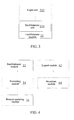
- Fig. 3 is a preferable structural block diagram of the establishment module 22 according to an embodiment of the present invention.
- the establishment module 22 may include: a login unit 222, configured to log in an XMPP server using the same account as that of the first DLNA gateway; and an establishment unit 224 connected to the login unit 222 and configured to establish a data channel with the first DLNA gateway.
- Fig. 4 is a preferable structural block diagram of an apparatus for sharing a DLNA device according to an embodiment of the present invention.
- the apparatus may further include: a logout module 42, connected to the establishment module 22 and configured to log out the account; and a broadcast module 44 connected to the logout module 42 and configured to broadcast that the virtual DLNA device leaves the second DLNA network in the second DLNA network through an SSDP message.
- Fig. 5 is a preferable structural block diagram of the processing module 24 according to an embodiment of the present invention.
- the processing module 24 may include: a reception module 242, configured to receive the SSDP message broadcasted by the DLNA device in the first DLNA network transmitted by the first DLNA gateway through the data channel; an adding module 244 connected to the reception module 242 and configured to add the virtual DLNA device corresponding to the DLNA device; and a first transformation module 246 connected to the adding module 244 and configured to amend the first URL in the SSDP message to a second URL within the second DLNA network of the second DLNA gateway as a URL of the virtual DLNA device, and broadcast the amended SSDP message in the second DLNA network in a case that the SSDP message comprises a first URL within the first DLNA network of the DLNA device in the first DLNA network.
- Fig. 6 is a preferable structural block diagram of the remote operating module 26 according to an embodiment of the present invention.
- the remote operating module 26 may include: a second transformation module 266, configured to transform a message for remote control and/or remote play transmitted by the DLNA device in the second DLNA network to the virtual DLNA device from an HTTP format into an UDP format, and transmit the transformed message to the first DLNA gateway through the data channel; and further configured to transform a response message corresponding to the message returned by the first DLNA gateway from the UDP format into the HTTP format, and forward the transformed response message to the DLNA device performing remote control and/or remote play.
- the following preferable embodiments primarily relate to a method for interconnecting two or more digital home networks.
- a new device type of a DLNA gateway is introduced, and interconnection among more than two DLNA networks is implemented by interconnection between two DLNA gateways.
- a DLNA device type for example, DMS and DMR
- another DLNA network is virtualized in the role of the DLNA gateway device, so that the DLNA devices of different DLNA networks can find and control each other, and finally implement sharing of multimedia resources across DLNA networks and expand the DLNA sharing on the internet.
- Fig. 7 is a structural diagram of interconnection between DLNA networks according to embodiment one of the present invention.
- a television as a DMP and a DMR
- a mobile terminal as a DMC
- a DMS and a DMP
- a PC with four DLNA device roles
- a Customer Premises Equipment (CPE) with a DMS function in the first DLNA network.
- CPE Customer Premises Equipment
- These personal customer electronic devices are connected through routers, have the IP address of the same subnet, and constitute a digital home network capable of DLNA sharing.
- Other DLNA networks also have similar networking structures, for example a second DLNA network shown in Fig. 7 .
- a DLNA gateway In order to achieve interconnection between two DLNA networks, it needs to select one from the personal customer electronic devices in digital home network as a DLNA gateway to communicate with another home network.
- This device is capable of accessing an XMPP server.
- a CPE device In the preferable embodiment, a CPE device is selected to act as the device.
- Other devices can also be selected, for example, a mobile terminal or a television.
- the DLNA gateway device selected by a user needs to register an Extensible Messaging and Presence Protocol (XMPP) account on a server of the internet, and logs in the XMPP server in the embodiment of the present invention through the account.
- the DLNA gateways of other DLNA networks may also log in the XMPP server with the same account.
- XMPP Extensible Messaging and Presence Protocol
- this XMPP account associates the DLNA gateways of different DLNA networks. Each DLNA gateway may actually have its own unique identity.
- the XMPP server uses identities of the DLNA gateways associated therewith as a group, in which the DLNA gateways share presentation information. Therefore, after the user logs in the DLNA gateway of the second DLNA network, the DLNA gateway of the first DLNA network can be aware of interconnection between the first DLNA network and the second DLNA network to be implemented by the user, and the XMPP server will notify information that the second DLNA gateway is online to the first DLNA gateway.
- the first DLNA gateway and the second DLNA gateway may negotiate to establish a data channel using an XMPP protocol.
- the data channel can be used for P2P data transmission using a UDP protocol, thereby avoiding passing through the XMPP server.
- UDP protocol a protocol for P2P data transmission
- NAT Network Address Translation
- the DLNA gateway may transmit an SSDP message of a DLNA network where it is located to another DLNA gateway through the data channel.
- the SSDP uses HTTP over UDP, and the established data channel is also a UDP tunnel. Therefore, the SSDP can be directly transmitted to another DLNA gateway through the UDP tunnel, and the original multicast message needs to be changed into a unicast message.
- virtual DMS and DMR devices of another DLNA network are added and deleted on the DLNA gateway according to whether it is a device join notification or leave notification and keep-alive notification.
- Device description information and service description information of the virtual DMS and DMR devices are acquired from a target DLNA gateway through a data channel.
- This acquisition process uses HTTP over TCP, and therefore it needs to use pseudo TCP tunnel on the UDP data channel for traffic control and transmission to transmit TCP data to another DLNA gateway through the pseudo TCP tunnel.
- the target DLNA gateway acquires the device description and service description information of the virtual DMS and DMR from the source DLNA gateway, and then broadcasts the information through the SSDP protocol in the DLNA network where it is located.
- Other DLNA devices in the DLNA network can be aware of the description information and control information of the virtual DMS and DMR devices and implement the same control and presentation as those of the DMS and DMR devices in the current DLNA network, so as to realize localized sharing of remote DMS and DMR.
- the local DMS and DMR devices are also similarly shared in the first DLNA network through the DLNA gateway.
- the DMS and DMR devices of the two DLNA networks can access each other through the DLNA gateways to realize sharing of media resources across the DLNA networks.
- the media resource items shared by the virtual DMS may not have the same resource URLs as those of the resource items of the actual DMS devices.
- the URLs thereof may be reconfigured by the DLNA gateway according to the IP address of its own. Therefore, when a resource request of a local DLNA network is received, the DLNA gateway needs to acquire resources from the target DLNA gateway through a data channel which is established before, the target DLNA gateway requests DMS resources through the HTTP protocol, and then transmits the multimedia data to the source DLNA gateway through the data channel by a protocol transformation, and the source DLNA gateway transmits the multimedia data to the related DLNA device of the local DLNA network through the HTTP protocol.
- the DLNA gateway acts as different DLNA device roles according to different positions where it is located, and transforms the transmission protocol.
- the above source DLNA gateway is used as a DMS, and forwards the resource request of the virtual DMS to the target DLNA gateway; while the target DLNA gateway acts as a DMP, acquires media data of the actual DMS resources, does not perform operations, and transmits the media data to the source DLNA through the data channel.
- the virtual DMS and DMR of the two DLNA networks will be unavailable immediately, and the DLNA gateway broadcasts that the virtual DMS and DMR leave the DLNA network to its own DLNA network through the SSDP protocol.
- the DLNA gateway will broadcast that DMS and DMR devices of the other DLNA network leave the DLNA network through the SSDP protocol, and the other DLNA gateway broadcasts that the virtual DMS and DMR of the DLNA network leave its own DLNA network through the SSDP protocol by an offline notification of the XMPP server.
- a user can interconnect DLNA networks at different positions.
- the user has its own DLNA networks at home and in workplace.
- the user uses the home network in the workplace and the user's family is at home; and the user finds interested media resources to be shared to the home network at home, the user's family can see the media resources only by the user assigning the media resources to the virtual DMR of the DLNA gateway for play.
- the user uploads the media resources on the virtual DMS of the DLNA and then the user's family can also see the media resources by viewing the local DMS server.
- the user can remotely control the DLNA device at home, for example, playing specified media contents to the family without control by the family.
- Fig. 8 is a flowchart of network interaction of interconnection between DLNA networks according to embodiment two of the present invention.
- Fig. 8 in order to simplification of the description, only the interaction between the DMS and the DLNA GATEWAY1 is described in the first DLNA network, and only one DMR and DLNA GATEWAY2 occur in the second DLNA network.
- the network interconnection solution according to the present preferable embodiment may also be extended to interconnection among more than three DLNA networks. The present preferable embodiment will be described only by taking interconnection between two DLNA networks as an example.
- a DLNA gateway selected by the user Before implementing interconnection between two DLNA networks, a user needs to apply to an XMPP server for an account, a DLNA gateway selected by the user must have a capability of internet access, and other DLNA devices in the DLNA network may not have such capability.
- the following description primarily relates to a flow of interaction of interconnection protocol message between two DLNA gateways, a process of device discovery in the two DLNA networks (including a local DLNA device and a virtual DLNA device) and a flow of protocol transformation and message interaction when a local DLNA terminal acquires a remote DLNA network for play. Other flows are the same as the above, and the description thereof will be omitted here.
- step S804 if an XMPP server which has a login identity associated with the XMPP account has been logged in, the presentation information thereof is transmitted to the XMPP server, i.e., the user wants to interconnect with another DLNA network.
- the XMPP server does not have the presentation information of the DLNA gateway 2.
- step S806 the DLNA gateway 2 uses the same method to log in the XMPP server.
- step S808 the XMPP server discovers that the DLNA gateway 1 associated with the XMPP account is online, and notifies the information that the DLNA gateway 2 is online to the DLNA gateway 1.
- the XMPP server also notifies the DLNA gateway 2 of information that the DLNA gateway 1 is already online.
- the user wants to implement interconnection between the DLNA network where the DLNA gateway 1 is located and the DLNA network where the DLNA gateway 2 is located.
- step S812 the DLNA gateway 1 negotiates the data channel with the DLNA gateway 2 through an XMPP:JINGLE protocol.
- the above negotiation process needs to be relayed through the XMPP server.
- a session is initiated to transmit a transmission method of the DLNA gateway 1 (UDP, TCP and ICE-UDP, ICE-TCP) to the DLNA gateway 2 through the XMPP server, and the DLNA gateway 2 will firstly confirm the message, and then tries to acquire a transmission method for successful connection between the DLNA gateway 2 and the DLNA gateway 1 according to the transmission method of the DLNA gateway 1.
- the P2P transmission may be performed through a UDP or a TCP; and if there is NAT traversal, the ICE-UDP mode may be used and the P2P transmission may be performed through a relay.
- step S814 after completing enquiry of the transmission method, the DLNA gateway 2 transmits session acceptance information through an XMPP: JINGLE protocol, and the DLNA gateway 1 confirms the information and completes negotiation of the data channel with the DLNA gateway 2.
- XMPP JINGLE protocol
- step S816 according to the transmission method in the above negotiation result, the DLNA gateway 1 and the DLNA gateway 2 establish the data channel, and due to the difference in networking between the DLNA gateways, the P2P transmission may be performed through a relay.
- step S818 a DMS is added in the first DLNA network, and is broadcast in the first DLNA network through the SSDP protocol.
- step S820 the DLNA gateway 1, as a DMC device role, receives an SSDP message of the DMS, and discovers that a new DLNA device is added in the local DLNA network.
- step S822 the DLNA gateway 1 encapsulates the received SSDP message into the data channel and then transmits it to the DLNA gateway 2.
- step S824 the DLNA gateway 2 parses the SSDP message, discovers that the DMS of the first DLNA network is added in the DLNA network, and acquires device description and service description information of the DMS from the first DLNA gateway through the data channel. All of these interaction processes are transmitted through the above negotiated data channel.
- step S826 the DLNA gateway 2 amends the URL of the acquired device description information and service description information of the DMS, substitutes it with a local IP address, and broadcasts an SSDP message to the second DLNA network to notify that the virtual DMS is added in the DLNA network.
- step S828 the DMR in the second DLNA network also uses the above steps S818-S826, and there is a virtual DMR in the first DLNA network.
- the virtual DLNA device which is added and deleted can perform remote play and remote control, for example, in the second DLNA network, the function of remote play is implemented by playing resources of the virtual DMS using the DMP/DMR; and the function of remote control is implemented by the DMC controlling the virtual DMR to play particular contents.
- step S830 in the second DLNA network, the DMC specifies the DMR to play media contents of the virtual DMS, and the DMR requests media contents from the DMS started by the DLNA gateway 2; and the there is difference between the URL of the media resource items of the virtual DMS and the URL of the media resource items of the actual DMS, the former uses an IP address of the DLNA gateway 2 as a host address, and the latter uses the current IP address as a host address.
- the DLNA gateway 2 receives a resource request of the virtual DMS, can request actual resources from the DLNA gateway 1 through Universally Unique Identifiers (UUIDs) of the actual DMS device and the virtual DMS device, and performs protocol data transformation. Different DMS and DMR devices can be distinguished globally through the UUIDs.
- the DLNA gateway 2 can directly access the DLNA device in the first DLNA network through the UUID.
- step S834 the resource request is transmitted to the DLNA gateway 1 through the data channel which is established before.
- step S836 at this time, the DLNA gateway 1, as a DMP device role, requests multimedia resources from the DMS.
- step S838 the DMS receives the media resource request of the DLNA gateway 1, and processes it in accordance with the local DLNA sharing.
- step S840 the DMS responds to the above HTTP request of the resources, and transmits the media resource data to the DLNA gateway 1, and the DLNA gateway 1 can performs a protocol transformation process.
- step S842 the DLNA gateway 1 transmits the HTTP response message to the DLNA gateway 2 through the data channel.
- step S844 the DLNA gateway 2 performs protocol data transformation process, transmits the media resource data to the DMR device through a standard HTTP response, and the DMR starts to buffer and play the media resource data, and finally enables the DMR of the second DLNA network to play the media resources shared by the DMS of the first DLNA network.
- the DMS and the DLNA gateway 1 can perform a process using a standard HTTP protocol
- the DLNA gateway 1 and the DLNA gateway 2 can perform data transmission using the data channel negotiated by the XMPP: JINGLE
- the DLNA gateway 2 and the DMR can interact using a standard HTTP protocol.
- the DLNA gateway 1 and the DLNA gateway 2 can perform a protocol transformation work, to transform the data in the data channel into HTTP protocol encapsulation, and then transform the HTTP protocol into a data encapsulation format of the data channel.
- Such process is transparent to the device of the DLNA network, and the device of the DLNA network needs not to know the protocol transformation process.
- the protocol for accessing the DLNA device is an HTTP protocol
- the HTTP protocol can be transformed into a UDP protocol on the DLNA gateway.
- the first DLNA network and the second DLNA network negotiate a UDP channel through an XMPP protocol, which is used to implement communication between the virtual DMS/DMR device and the DLNA gateway, thereby achieving the purpose of accessing the actual DLNA device.
- a storage medium which stores the above software and includes but is not limited to an optical disc, a floppy disk, hardware, an erasable memory, etc.
- a data channel is established between a first DLNA gateway in a first DLNA network and a second DLNA gateway in a second DLNA network, wherein the DLNA gateway is a DLNA device having a DMC function and capable of accessing the Internet; a virtual DLNA device corresponding to a DLNA device in the first DLNA network is added in the second DLNA gateway; and a DLNA device in the second DLNA network performs remote control and/or remote play for the DLNA device in the first DLNA network through the virtual DLNA device.
Landscapes
- Engineering & Computer Science (AREA)
- Computer Networks & Wireless Communication (AREA)
- Signal Processing (AREA)
- Automation & Control Theory (AREA)
- Computing Systems (AREA)
- Multimedia (AREA)
- Health & Medical Sciences (AREA)
- General Health & Medical Sciences (AREA)
- Medical Informatics (AREA)
- General Business, Economics & Management (AREA)
- Business, Economics & Management (AREA)
- Data Exchanges In Wide-Area Networks (AREA)
- Computer And Data Communications (AREA)
Applications Claiming Priority (2)
| Application Number | Priority Date | Filing Date | Title |
|---|---|---|---|
| CN201210290213.3A CN102811223B (zh) | 2012-08-15 | 2012-08-15 | Dlna设备共享方法及装置 |
| PCT/CN2013/079309 WO2013178142A1 (fr) | 2012-08-15 | 2013-07-12 | Procédé et dispositif pour partager un disposiitif dlna |
Publications (3)
| Publication Number | Publication Date |
|---|---|
| EP2833596A1 true EP2833596A1 (fr) | 2015-02-04 |
| EP2833596A4 EP2833596A4 (fr) | 2015-07-15 |
| EP2833596B1 EP2833596B1 (fr) | 2017-12-06 |
Family
ID=47234798
Family Applications (1)
| Application Number | Title | Priority Date | Filing Date |
|---|---|---|---|
| EP13796843.4A Active EP2833596B1 (fr) | 2012-08-15 | 2013-07-12 | Procédé et dispositif pour partager un dispositif dlna |
Country Status (4)
| Country | Link |
|---|---|
| US (1) | US9948686B2 (fr) |
| EP (1) | EP2833596B1 (fr) |
| CN (1) | CN102811223B (fr) |
| WO (1) | WO2013178142A1 (fr) |
Cited By (2)
| Publication number | Priority date | Publication date | Assignee | Title |
|---|---|---|---|---|
| EP2913961A1 (fr) * | 2014-02-27 | 2015-09-02 | BSH Hausgeräte GmbH | Procédé et système destinés à la télécommande et/ou à la télésurveillance du fonctionnement d'un appareil ménager à l'aide d'un appareil de communication |
| EP3772201A1 (fr) * | 2019-07-31 | 2021-02-03 | Deutsche Telekom AG | Procédé de fourniture automatique de données relatives à l'utilisateur à l'aide d'un réseau domestique ainsi que programme informatique |
Families Citing this family (15)
| Publication number | Priority date | Publication date | Assignee | Title |
|---|---|---|---|---|
| CN102811223B (zh) * | 2012-08-15 | 2018-10-09 | 中兴通讯股份有限公司 | Dlna设备共享方法及装置 |
| CN103973638B (zh) * | 2013-01-28 | 2018-08-10 | 联想(北京)有限公司 | 访问控制方法、电子设备和服务器 |
| US20150012668A1 (en) * | 2013-07-04 | 2015-01-08 | Arcsoft Hangzhou Co., Ltd. | Method of Communicating Between Multiple Digital Living Network Alliance Networks |
| CN103414713A (zh) * | 2013-08-05 | 2013-11-27 | 三星电子(中国)研发中心 | 一种访问云端媒体资源的方法、装置和dlna设备 |
| CN104426989B (zh) * | 2013-09-09 | 2018-12-14 | 联想(北京)有限公司 | 数据呈现方法、数据请求方法及电子设备 |
| DE102013018596A1 (de) * | 2013-11-07 | 2015-05-07 | Phoenix Contact Gmbh & Co. Kg | Netzwerksystem, Koppeleinheit und Verfahren zum Betreiben eines Netzwerksystems |
| WO2015089702A1 (fr) * | 2013-12-16 | 2015-06-25 | Harman International Industries, Incorporated | Communications basées dlna entre des sous-réseaux |
| CN103888515B (zh) * | 2014-02-26 | 2017-12-12 | 四川长虹电器股份有限公司 | 基于浏览器的媒体资源分享方法 |
| CN105323125B (zh) * | 2014-07-25 | 2020-03-31 | 中兴通讯股份有限公司 | 一种跨家庭网络的处理方法及http网关、dlna设备 |
| CN105828174B (zh) * | 2015-01-05 | 2019-11-05 | 中兴通讯股份有限公司 | 一种分享媒体内容的方法和装置 |
| US10419497B2 (en) * | 2015-03-31 | 2019-09-17 | Bose Corporation | Establishing communication between digital media servers and audio playback devices in audio systems |
| CN108111556A (zh) * | 2016-11-24 | 2018-06-01 | 深圳市优朋普乐传媒发展有限公司 | 一种数据传输方法及系统 |
| CN111064594B (zh) * | 2018-10-17 | 2022-08-12 | 中兴通讯股份有限公司 | 网关的信息处理方法、网关、账号管理系统及存储介质 |
| CN109857711B (zh) * | 2019-01-04 | 2021-03-02 | 烽火通信科技股份有限公司 | 一种基于vCPE的家庭网络媒体分享方法及系统 |
| CN114697880B (zh) * | 2020-12-31 | 2023-05-12 | 华为技术有限公司 | 跨网段发现的方法、路由设备及系统 |
Family Cites Families (10)
| Publication number | Priority date | Publication date | Assignee | Title |
|---|---|---|---|---|
| US20070211734A1 (en) * | 2006-03-10 | 2007-09-13 | Kuo-Long Yang | Digital living network alliance gateway having integrated website server for remote access and method thereof |
| KR100789425B1 (ko) * | 2006-04-10 | 2007-12-28 | 삼성전자주식회사 | 디.엘.엔.에이 네트워크를 이용한 컨텐츠 공유 방법 |
| US7827275B2 (en) * | 2006-06-08 | 2010-11-02 | Samsung Electronics Co., Ltd. | Method and system for remotely accessing devices in a network |
| JP2008236344A (ja) * | 2007-03-20 | 2008-10-02 | Hitachi Ltd | プロキシ装置、ネットワークシステムおよび通信方法 |
| EP2425348A4 (fr) * | 2009-05-01 | 2015-09-02 | Ericsson Telefon Ab L M | Système et procédé de traitement d'informations assurant un service composé |
| JP5517733B2 (ja) * | 2010-05-12 | 2014-06-11 | 株式会社日立ソリューションズ | コンテンツ配信システム、及びゲートウェイ装置、並びにプログラム |
| US9003044B2 (en) * | 2010-07-26 | 2015-04-07 | T-Mobile Usa, Inc. | Home hub for IP multimedia subsystem (IMS)/Web services interaction |
| CN102340496B (zh) | 2010-07-28 | 2014-08-13 | 鸿富锦精密工业(深圳)有限公司 | 数字媒体控制器及利用其共享网络间媒体内容的方法 |
| CN102480461B (zh) | 2010-11-22 | 2014-12-10 | 北京闪联云视信息技术有限公司 | 一种实现远程协同应用的方法与系统 |
| CN102811223B (zh) * | 2012-08-15 | 2018-10-09 | 中兴通讯股份有限公司 | Dlna设备共享方法及装置 |
-
2012
- 2012-08-15 CN CN201210290213.3A patent/CN102811223B/zh active Active
-
2013
- 2013-07-12 WO PCT/CN2013/079309 patent/WO2013178142A1/fr not_active Ceased
- 2013-07-12 US US14/398,279 patent/US9948686B2/en active Active
- 2013-07-12 EP EP13796843.4A patent/EP2833596B1/fr active Active
Cited By (2)
| Publication number | Priority date | Publication date | Assignee | Title |
|---|---|---|---|---|
| EP2913961A1 (fr) * | 2014-02-27 | 2015-09-02 | BSH Hausgeräte GmbH | Procédé et système destinés à la télécommande et/ou à la télésurveillance du fonctionnement d'un appareil ménager à l'aide d'un appareil de communication |
| EP3772201A1 (fr) * | 2019-07-31 | 2021-02-03 | Deutsche Telekom AG | Procédé de fourniture automatique de données relatives à l'utilisateur à l'aide d'un réseau domestique ainsi que programme informatique |
Also Published As
| Publication number | Publication date |
|---|---|
| US20150089025A1 (en) | 2015-03-26 |
| EP2833596B1 (fr) | 2017-12-06 |
| CN102811223A (zh) | 2012-12-05 |
| US9948686B2 (en) | 2018-04-17 |
| CN102811223B (zh) | 2018-10-09 |
| WO2013178142A1 (fr) | 2013-12-05 |
| EP2833596A4 (fr) | 2015-07-15 |
Similar Documents
| Publication | Publication Date | Title |
|---|---|---|
| EP2833596B1 (fr) | Procédé et dispositif pour partager un dispositif dlna | |
| CN101473597B (zh) | 远程访问通用即插即用装置的方法和系统 | |
| US8307093B2 (en) | Remote access between UPnP devices | |
| US20110153845A1 (en) | Methods and apparatus for establishing network connections using an inter-mediating device | |
| EP2237476B1 (fr) | Dispositif upnp pour fourni un service d'accès distant et son procédé | |
| CN105409183A (zh) | 用于在html5应用中实现任何网络功能客户端或服务器的系统和设备 | |
| US9660873B2 (en) | Method and apparatus for providing remote access service | |
| EP3029887A1 (fr) | Appareil et procédé permettant de fournir des informations de réseau domestique accessibles dans un environnement d'accès à distance | |
| US20230054029A1 (en) | Methods and systems for proxy relay implementation for client-server connections over wide area network | |
| JP2009010606A (ja) | トンネル接続システム、トンネル管理サーバ、トンネル接続装置、及びトンネル接続方法 | |
| WO2014059441A1 (fr) | Identification de serveurs par adresses de réseau étendu commun | |
| US9413590B2 (en) | Method for management of a secured transfer session through an address translation device, corresponding server and computer program | |
| US8031641B2 (en) | Method and system for serving multi-media data between hetero UPnP networks | |
| US9226223B2 (en) | Network connection system of network electronic device and method allowing a terminal device to access an electronic device connected behind a router without a NAT loopback function | |
| CN116708381B (zh) | 跨网络的数据传输方法、装置和存储介质及电子设备 | |
| US8379533B2 (en) | Universal plug and play method and apparatus to provide remote access service | |
| Hwang et al. | Personal mobile A/V control point for home-to-home media streaming | |
| TWI801077B (zh) | 用於私有通訊架構的連接方法與電腦可讀取媒體 | |
| CN105323125B (zh) | 一种跨家庭网络的处理方法及http网关、dlna设备 | |
| KR101418250B1 (ko) | 원격 접속 서비스를 제공하는 방법 및 그 장치 | |
| Tien et al. | H-box: Interconnecting devices across local networks | |
| JP2008048110A (ja) | セキュアなシグナリングチャネルを用いたリソース更新方法、サーバ、端末及びプログラム |
Legal Events
| Date | Code | Title | Description |
|---|---|---|---|
| PUAI | Public reference made under article 153(3) epc to a published international application that has entered the european phase |
Free format text: ORIGINAL CODE: 0009012 |
|
| 17P | Request for examination filed |
Effective date: 20141031 |
|
| AK | Designated contracting states |
Kind code of ref document: A1 Designated state(s): AL AT BE BG CH CY CZ DE DK EE ES FI FR GB GR HR HU IE IS IT LI LT LU LV MC MK MT NL NO PL PT RO RS SE SI SK SM TR |
|
| AX | Request for extension of the european patent |
Extension state: BA ME |
|
| RA4 | Supplementary search report drawn up and despatched (corrected) |
Effective date: 20150615 |
|
| RIC1 | Information provided on ipc code assigned before grant |
Ipc: H04L 12/28 20060101ALI20150609BHEP Ipc: H04L 12/46 20060101ALI20150609BHEP Ipc: H04L 29/08 20060101ALI20150609BHEP Ipc: H04L 29/06 20060101AFI20150609BHEP |
|
| DAX | Request for extension of the european patent (deleted) | ||
| STAA | Information on the status of an ep patent application or granted ep patent |
Free format text: STATUS: EXAMINATION IS IN PROGRESS |
|
| 17Q | First examination report despatched |
Effective date: 20161027 |
|
| GRAP | Despatch of communication of intention to grant a patent |
Free format text: ORIGINAL CODE: EPIDOSNIGR1 |
|
| STAA | Information on the status of an ep patent application or granted ep patent |
Free format text: STATUS: GRANT OF PATENT IS INTENDED |
|
| INTG | Intention to grant announced |
Effective date: 20170704 |
|
| GRAS | Grant fee paid |
Free format text: ORIGINAL CODE: EPIDOSNIGR3 |
|
| GRAA | (expected) grant |
Free format text: ORIGINAL CODE: 0009210 |
|
| STAA | Information on the status of an ep patent application or granted ep patent |
Free format text: STATUS: THE PATENT HAS BEEN GRANTED |
|
| AK | Designated contracting states |
Kind code of ref document: B1 Designated state(s): AL AT BE BG CH CY CZ DE DK EE ES FI FR GB GR HR HU IE IS IT LI LT LU LV MC MK MT NL NO PL PT RO RS SE SI SK SM TR |
|
| REG | Reference to a national code |
Ref country code: GB Ref legal event code: FG4D |
|
| REG | Reference to a national code |
Ref country code: AT Ref legal event code: REF Ref document number: 953327 Country of ref document: AT Kind code of ref document: T Effective date: 20171215 Ref country code: CH Ref legal event code: EP |
|
| REG | Reference to a national code |
Ref country code: IE Ref legal event code: FG4D |
|
| REG | Reference to a national code |
Ref country code: DE Ref legal event code: R096 Ref document number: 602013030519 Country of ref document: DE |
|
| REG | Reference to a national code |
Ref country code: NL Ref legal event code: MP Effective date: 20171206 |
|
| REG | Reference to a national code |
Ref country code: LT Ref legal event code: MG4D |
|
| PG25 | Lapsed in a contracting state [announced via postgrant information from national office to epo] |
Ref country code: SE Free format text: LAPSE BECAUSE OF FAILURE TO SUBMIT A TRANSLATION OF THE DESCRIPTION OR TO PAY THE FEE WITHIN THE PRESCRIBED TIME-LIMIT Effective date: 20171206 Ref country code: LT Free format text: LAPSE BECAUSE OF FAILURE TO SUBMIT A TRANSLATION OF THE DESCRIPTION OR TO PAY THE FEE WITHIN THE PRESCRIBED TIME-LIMIT Effective date: 20171206 Ref country code: NO Free format text: LAPSE BECAUSE OF FAILURE TO SUBMIT A TRANSLATION OF THE DESCRIPTION OR TO PAY THE FEE WITHIN THE PRESCRIBED TIME-LIMIT Effective date: 20180306 Ref country code: FI Free format text: LAPSE BECAUSE OF FAILURE TO SUBMIT A TRANSLATION OF THE DESCRIPTION OR TO PAY THE FEE WITHIN THE PRESCRIBED TIME-LIMIT Effective date: 20171206 Ref country code: ES Free format text: LAPSE BECAUSE OF FAILURE TO SUBMIT A TRANSLATION OF THE DESCRIPTION OR TO PAY THE FEE WITHIN THE PRESCRIBED TIME-LIMIT Effective date: 20171206 |
|
| REG | Reference to a national code |
Ref country code: AT Ref legal event code: MK05 Ref document number: 953327 Country of ref document: AT Kind code of ref document: T Effective date: 20171206 |
|
| PG25 | Lapsed in a contracting state [announced via postgrant information from national office to epo] |
Ref country code: LV Free format text: LAPSE BECAUSE OF FAILURE TO SUBMIT A TRANSLATION OF THE DESCRIPTION OR TO PAY THE FEE WITHIN THE PRESCRIBED TIME-LIMIT Effective date: 20171206 Ref country code: RS Free format text: LAPSE BECAUSE OF FAILURE TO SUBMIT A TRANSLATION OF THE DESCRIPTION OR TO PAY THE FEE WITHIN THE PRESCRIBED TIME-LIMIT Effective date: 20171206 Ref country code: HR Free format text: LAPSE BECAUSE OF FAILURE TO SUBMIT A TRANSLATION OF THE DESCRIPTION OR TO PAY THE FEE WITHIN THE PRESCRIBED TIME-LIMIT Effective date: 20171206 Ref country code: GR Free format text: LAPSE BECAUSE OF FAILURE TO SUBMIT A TRANSLATION OF THE DESCRIPTION OR TO PAY THE FEE WITHIN THE PRESCRIBED TIME-LIMIT Effective date: 20180307 Ref country code: BG Free format text: LAPSE BECAUSE OF FAILURE TO SUBMIT A TRANSLATION OF THE DESCRIPTION OR TO PAY THE FEE WITHIN THE PRESCRIBED TIME-LIMIT Effective date: 20180306 |
|
| PG25 | Lapsed in a contracting state [announced via postgrant information from national office to epo] |
Ref country code: NL Free format text: LAPSE BECAUSE OF FAILURE TO SUBMIT A TRANSLATION OF THE DESCRIPTION OR TO PAY THE FEE WITHIN THE PRESCRIBED TIME-LIMIT Effective date: 20171206 |
|
| REG | Reference to a national code |
Ref country code: FR Ref legal event code: PLFP Year of fee payment: 6 |
|
| PG25 | Lapsed in a contracting state [announced via postgrant information from national office to epo] |
Ref country code: EE Free format text: LAPSE BECAUSE OF FAILURE TO SUBMIT A TRANSLATION OF THE DESCRIPTION OR TO PAY THE FEE WITHIN THE PRESCRIBED TIME-LIMIT Effective date: 20171206 Ref country code: SK Free format text: LAPSE BECAUSE OF FAILURE TO SUBMIT A TRANSLATION OF THE DESCRIPTION OR TO PAY THE FEE WITHIN THE PRESCRIBED TIME-LIMIT Effective date: 20171206 Ref country code: CZ Free format text: LAPSE BECAUSE OF FAILURE TO SUBMIT A TRANSLATION OF THE DESCRIPTION OR TO PAY THE FEE WITHIN THE PRESCRIBED TIME-LIMIT Effective date: 20171206 |
|
| PG25 | Lapsed in a contracting state [announced via postgrant information from national office to epo] |
Ref country code: AT Free format text: LAPSE BECAUSE OF FAILURE TO SUBMIT A TRANSLATION OF THE DESCRIPTION OR TO PAY THE FEE WITHIN THE PRESCRIBED TIME-LIMIT Effective date: 20171206 Ref country code: PL Free format text: LAPSE BECAUSE OF FAILURE TO SUBMIT A TRANSLATION OF THE DESCRIPTION OR TO PAY THE FEE WITHIN THE PRESCRIBED TIME-LIMIT Effective date: 20171206 Ref country code: IT Free format text: LAPSE BECAUSE OF FAILURE TO SUBMIT A TRANSLATION OF THE DESCRIPTION OR TO PAY THE FEE WITHIN THE PRESCRIBED TIME-LIMIT Effective date: 20171206 Ref country code: SM Free format text: LAPSE BECAUSE OF FAILURE TO SUBMIT A TRANSLATION OF THE DESCRIPTION OR TO PAY THE FEE WITHIN THE PRESCRIBED TIME-LIMIT Effective date: 20171206 Ref country code: RO Free format text: LAPSE BECAUSE OF FAILURE TO SUBMIT A TRANSLATION OF THE DESCRIPTION OR TO PAY THE FEE WITHIN THE PRESCRIBED TIME-LIMIT Effective date: 20171206 |
|
| REG | Reference to a national code |
Ref country code: DE Ref legal event code: R097 Ref document number: 602013030519 Country of ref document: DE |
|
| PLBE | No opposition filed within time limit |
Free format text: ORIGINAL CODE: 0009261 |
|
| STAA | Information on the status of an ep patent application or granted ep patent |
Free format text: STATUS: NO OPPOSITION FILED WITHIN TIME LIMIT |
|
| 26N | No opposition filed |
Effective date: 20180907 |
|
| PG25 | Lapsed in a contracting state [announced via postgrant information from national office to epo] |
Ref country code: SI Free format text: LAPSE BECAUSE OF FAILURE TO SUBMIT A TRANSLATION OF THE DESCRIPTION OR TO PAY THE FEE WITHIN THE PRESCRIBED TIME-LIMIT Effective date: 20171206 Ref country code: DK Free format text: LAPSE BECAUSE OF FAILURE TO SUBMIT A TRANSLATION OF THE DESCRIPTION OR TO PAY THE FEE WITHIN THE PRESCRIBED TIME-LIMIT Effective date: 20171206 |
|
| REG | Reference to a national code |
Ref country code: CH Ref legal event code: PL |
|
| PG25 | Lapsed in a contracting state [announced via postgrant information from national office to epo] |
Ref country code: MC Free format text: LAPSE BECAUSE OF FAILURE TO SUBMIT A TRANSLATION OF THE DESCRIPTION OR TO PAY THE FEE WITHIN THE PRESCRIBED TIME-LIMIT Effective date: 20171206 Ref country code: LU Free format text: LAPSE BECAUSE OF NON-PAYMENT OF DUE FEES Effective date: 20180712 |
|
| REG | Reference to a national code |
Ref country code: BE Ref legal event code: MM Effective date: 20180731 |
|
| REG | Reference to a national code |
Ref country code: IE Ref legal event code: MM4A |
|
| PG25 | Lapsed in a contracting state [announced via postgrant information from national office to epo] |
Ref country code: IE Free format text: LAPSE BECAUSE OF NON-PAYMENT OF DUE FEES Effective date: 20180712 Ref country code: CH Free format text: LAPSE BECAUSE OF NON-PAYMENT OF DUE FEES Effective date: 20180731 Ref country code: LI Free format text: LAPSE BECAUSE OF NON-PAYMENT OF DUE FEES Effective date: 20180731 |
|
| PG25 | Lapsed in a contracting state [announced via postgrant information from national office to epo] |
Ref country code: BE Free format text: LAPSE BECAUSE OF NON-PAYMENT OF DUE FEES Effective date: 20180731 |
|
| PG25 | Lapsed in a contracting state [announced via postgrant information from national office to epo] |
Ref country code: MT Free format text: LAPSE BECAUSE OF NON-PAYMENT OF DUE FEES Effective date: 20180712 |
|
| PG25 | Lapsed in a contracting state [announced via postgrant information from national office to epo] |
Ref country code: TR Free format text: LAPSE BECAUSE OF FAILURE TO SUBMIT A TRANSLATION OF THE DESCRIPTION OR TO PAY THE FEE WITHIN THE PRESCRIBED TIME-LIMIT Effective date: 20171206 |
|
| PG25 | Lapsed in a contracting state [announced via postgrant information from national office to epo] |
Ref country code: HU Free format text: LAPSE BECAUSE OF FAILURE TO SUBMIT A TRANSLATION OF THE DESCRIPTION OR TO PAY THE FEE WITHIN THE PRESCRIBED TIME-LIMIT; INVALID AB INITIO Effective date: 20130712 Ref country code: PT Free format text: LAPSE BECAUSE OF FAILURE TO SUBMIT A TRANSLATION OF THE DESCRIPTION OR TO PAY THE FEE WITHIN THE PRESCRIBED TIME-LIMIT Effective date: 20171206 |
|
| PG25 | Lapsed in a contracting state [announced via postgrant information from national office to epo] |
Ref country code: MK Free format text: LAPSE BECAUSE OF NON-PAYMENT OF DUE FEES Effective date: 20171206 Ref country code: CY Free format text: LAPSE BECAUSE OF FAILURE TO SUBMIT A TRANSLATION OF THE DESCRIPTION OR TO PAY THE FEE WITHIN THE PRESCRIBED TIME-LIMIT Effective date: 20171206 |
|
| PG25 | Lapsed in a contracting state [announced via postgrant information from national office to epo] |
Ref country code: AL Free format text: LAPSE BECAUSE OF FAILURE TO SUBMIT A TRANSLATION OF THE DESCRIPTION OR TO PAY THE FEE WITHIN THE PRESCRIBED TIME-LIMIT Effective date: 20171206 Ref country code: IS Free format text: LAPSE BECAUSE OF FAILURE TO SUBMIT A TRANSLATION OF THE DESCRIPTION OR TO PAY THE FEE WITHIN THE PRESCRIBED TIME-LIMIT Effective date: 20180406 |
|
| REG | Reference to a national code |
Ref country code: DE Ref legal event code: R079 Ref document number: 602013030519 Country of ref document: DE Free format text: PREVIOUS MAIN CLASS: H04L0029060000 Ipc: H04L0065000000 |
|
| PGFP | Annual fee paid to national office [announced via postgrant information from national office to epo] |
Ref country code: GB Payment date: 20250529 Year of fee payment: 13 |
|
| PGFP | Annual fee paid to national office [announced via postgrant information from national office to epo] |
Ref country code: FR Payment date: 20250610 Year of fee payment: 13 |
|
| PGFP | Annual fee paid to national office [announced via postgrant information from national office to epo] |
Ref country code: DE Payment date: 20250604 Year of fee payment: 13 |