EP2833662B1 - Drahtlose basisstation, drahtloses kommunikationssystem und drahtloses kommunikationsverfahren - Google Patents
Drahtlose basisstation, drahtloses kommunikationssystem und drahtloses kommunikationsverfahren Download PDFInfo
- Publication number
- EP2833662B1 EP2833662B1 EP13770028.2A EP13770028A EP2833662B1 EP 2833662 B1 EP2833662 B1 EP 2833662B1 EP 13770028 A EP13770028 A EP 13770028A EP 2833662 B1 EP2833662 B1 EP 2833662B1
- Authority
- EP
- European Patent Office
- Prior art keywords
- cell
- evaluation indicator
- base station
- radio base
- cells
- Prior art date
- Legal status (The legal status is an assumption and is not a legal conclusion. Google has not performed a legal analysis and makes no representation as to the accuracy of the status listed.)
- Not-in-force
Links
Images






Classifications
-
- H—ELECTRICITY
- H04—ELECTRIC COMMUNICATION TECHNIQUE
- H04W—WIRELESS COMMUNICATION NETWORKS
- H04W72/00—Local resource management
- H04W72/04—Wireless resource allocation
- H04W72/044—Wireless resource allocation based on the type of the allocated resource
- H04W72/046—Wireless resource allocation based on the type of the allocated resource the resource being in the space domain, e.g. beams
-
- H—ELECTRICITY
- H04—ELECTRIC COMMUNICATION TECHNIQUE
- H04B—TRANSMISSION
- H04B7/00—Radio transmission systems, i.e. using radiation field
- H04B7/02—Diversity systems; Multi-antenna system, i.e. transmission or reception using multiple antennas
- H04B7/04—Diversity systems; Multi-antenna system, i.e. transmission or reception using multiple antennas using two or more spaced independent antennas
- H04B7/06—Diversity systems; Multi-antenna system, i.e. transmission or reception using multiple antennas using two or more spaced independent antennas at the transmitting station
- H04B7/0613—Diversity systems; Multi-antenna system, i.e. transmission or reception using multiple antennas using two or more spaced independent antennas at the transmitting station using simultaneous transmission
- H04B7/0615—Diversity systems; Multi-antenna system, i.e. transmission or reception using multiple antennas using two or more spaced independent antennas at the transmitting station using simultaneous transmission of weighted versions of same signal
-
- H—ELECTRICITY
- H04—ELECTRIC COMMUNICATION TECHNIQUE
- H04B—TRANSMISSION
- H04B7/00—Radio transmission systems, i.e. using radiation field
- H04B7/02—Diversity systems; Multi-antenna system, i.e. transmission or reception using multiple antennas
- H04B7/04—Diversity systems; Multi-antenna system, i.e. transmission or reception using multiple antennas using two or more spaced independent antennas
- H04B7/06—Diversity systems; Multi-antenna system, i.e. transmission or reception using multiple antennas using two or more spaced independent antennas at the transmitting station
- H04B7/0697—Diversity systems; Multi-antenna system, i.e. transmission or reception using multiple antennas using two or more spaced independent antennas at the transmitting station using spatial multiplexing
-
- H—ELECTRICITY
- H04—ELECTRIC COMMUNICATION TECHNIQUE
- H04W—WIRELESS COMMUNICATION NETWORKS
- H04W16/00—Network planning, e.g. coverage or traffic planning tools; Network deployment, e.g. resource partitioning or cells structures
- H04W16/24—Cell structures
- H04W16/28—Cell structures using beam steering
-
- H—ELECTRICITY
- H04—ELECTRIC COMMUNICATION TECHNIQUE
- H04W—WIRELESS COMMUNICATION NETWORKS
- H04W52/00—Power management, e.g. Transmission Power Control [TPC] or power classes
- H04W52/04—Transmission power control [TPC]
- H04W52/06—TPC algorithms
- H04W52/14—Separate analysis of uplink or downlink
- H04W52/143—Downlink power control
-
- H—ELECTRICITY
- H04—ELECTRIC COMMUNICATION TECHNIQUE
- H04W—WIRELESS COMMUNICATION NETWORKS
- H04W52/00—Power management, e.g. Transmission Power Control [TPC] or power classes
- H04W52/04—Transmission power control [TPC]
- H04W52/30—Transmission power control [TPC] using constraints in the total amount of available transmission power
- H04W52/34—TPC management, i.e. sharing limited amount of power among users or channels or data types, e.g. cell loading
- H04W52/343—TPC management, i.e. sharing limited amount of power among users or channels or data types, e.g. cell loading taking into account loading or congestion level
-
- H—ELECTRICITY
- H04—ELECTRIC COMMUNICATION TECHNIQUE
- H04W—WIRELESS COMMUNICATION NETWORKS
- H04W16/00—Network planning, e.g. coverage or traffic planning tools; Network deployment, e.g. resource partitioning or cells structures
- H04W16/02—Resource partitioning among network components, e.g. reuse partitioning
- H04W16/06—Hybrid resource partitioning, e.g. channel borrowing
- H04W16/08—Load shedding arrangements
-
- H—ELECTRICITY
- H04—ELECTRIC COMMUNICATION TECHNIQUE
- H04W—WIRELESS COMMUNICATION NETWORKS
- H04W16/00—Network planning, e.g. coverage or traffic planning tools; Network deployment, e.g. resource partitioning or cells structures
- H04W16/24—Cell structures
- H04W16/30—Special cell shapes, e.g. doughnuts or ring cells
-
- H—ELECTRICITY
- H04—ELECTRIC COMMUNICATION TECHNIQUE
- H04W—WIRELESS COMMUNICATION NETWORKS
- H04W52/00—Power management, e.g. Transmission Power Control [TPC] or power classes
- H04W52/04—Transmission power control [TPC]
- H04W52/38—TPC being performed in particular situations
- H04W52/42—TPC being performed in particular situations in systems with time, space, frequency or polarisation diversity
-
- H—ELECTRICITY
- H04—ELECTRIC COMMUNICATION TECHNIQUE
- H04W—WIRELESS COMMUNICATION NETWORKS
- H04W72/00—Local resource management
- H04W72/04—Wireless resource allocation
- H04W72/044—Wireless resource allocation based on the type of the allocated resource
- H04W72/0446—Resources in time domain, e.g. slots or frames
-
- H—ELECTRICITY
- H04—ELECTRIC COMMUNICATION TECHNIQUE
- H04W—WIRELESS COMMUNICATION NETWORKS
- H04W72/00—Local resource management
- H04W72/50—Allocation or scheduling criteria for wireless resources
- H04W72/52—Allocation or scheduling criteria for wireless resources based on load
-
- H—ELECTRICITY
- H04—ELECTRIC COMMUNICATION TECHNIQUE
- H04W—WIRELESS COMMUNICATION NETWORKS
- H04W88/00—Devices specially adapted for wireless communication networks, e.g. terminals, base stations or access point devices
- H04W88/08—Access point devices
Definitions
- the present invention relates to a radio base station, a radio communication system and a radio communication method that are applicable to a next-generation mobile communication system.
- US 6,246,674 B1 discloses a system and a method for providing flexible sector shaping within a multiple sector cell.
- Document EP 0 531 090 A3 relates to re-use partition of cells in a mobile communication system.
- UMTS Universal Mobile Telecommunications System
- W-CDMA Wideband Code Division Multiple Access
- HSDPA High Speed Downlink Packet Access
- HSUPA High Speed Uplink Packet Access
- LTE long-term evolution
- a transmission rate of maximum approximately 2 Mbps can be achieved on the downlink by using a fixed band of approximately 5 MHz.
- a transmission rate of about maximum 300 Mbps on the downlink and about 75 Mbps on the uplink by using a variable band which ranges from 1.4 MHz to 20 MHz.
- successor systems of LTE are also under study for the purpose of achieving further broadbandization and higher speed (for example, "LTE-Advanced" (LTE-A)).
- LTE-A there is a plan to expand the maximum system band for LTE specifications, which is 20 MHz, to approximately 100 MHz.
- a MIMO (Multi Input Multi Output) system is proposed (see, for example, non-patent literature 1), as a radio communication technique to transmit and receive data by a plurality of antennas and improve the data rate (spectral efficiency).
- MIMO Multi Input Multi Output
- a plurality of transmitting/receiving antennas are provided in the transmitter/receiver, so that different transmission information sequences are transmitted from different transmitting antennas at the same time.
- the receiver side taking advantage of the fact that fading variation is produced differently between the transmitting/receiving antennas, it is possible to increase the data rate (spectral efficiency) by separating and detecting the information sequences that have been transmitted at the same time.
- VSEC vertical sectorization
- a proposal has been made to improve the throughput of each cell by outputting a plurality of beams having varying beam angles (tilt angles) with respect to horizontal directions from an antenna apparatus, and setting the tilt angles of the beams in accordance with the conditions of radio base stations (see, for example, non-patent literature 2).
- the present invention has been made in view of the above, and it is therefore an object of the present invention to allow effective use of radio resources in VSEC to output a plurality of beams of varying tilt angles for sectorization in vertical directions.
- the radio communication method of an example is a radio communication method for a radio base station that outputs a plurality of beams of varying tilt angles and forms a plurality of cells that are sectorized vertically, and a user terminal that establishes wireless connection with the radio base station, and this radio communication method provides the steps in which the radio base station acquires information about communication capacity of each of the plurality of cells, and controls a vertical plane beam width and/or transmission power of each cell and sets a coverage area of each cell such that differences in communication capacity between the plurality of cells are reduced.
- a radio base station outputs a plurality of beams with varying tilt angles via an antenna and forms a plurality of cells that are vertically sectorized.
- a case of forming two cells and a case of forming three or more cells will be described. Where two cells are vertically sectorized, one will be referred to as the "inner cell,” and the other one will be referred to as the "outer cell.”
- the "tilt angle” refers to the angle of beams with respect to horizontal directions (for example, the ground).
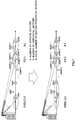
- FIG. 1 and FIG. 2 show that a plurality of beams with varying tilt angles are output from one antenna and a plurality of cells are vertically sectorized.
- FIG. 1A when two beams with mutually varying tilt angles are output, a cell (inner cell) that is relatively close to a radio base station and a cell (outer cell) that is relatively far are formed.
- the tilt angle of the beam forming the inner cell (inner tilt angle) is greater than the tilt angle of the beam forming the outer cell (outer tilt angle).
- FIG. 2A by increasing the number of beams having varying tilt angles, it is possible to increase the number of vertically sectorized cells.
- a plurality of cells that are vertically sectorized with respect to varying horizontal directions For example, in a two-cell configuration, a plurality of inner cells (here, cell #4 to cell #6) and outer cells (here, cell #1 to cell #3) are formed (see FIG. 1B ). Also, in a configuration with three or more cells, a plurality of cells that are vertically sectorized are formed (here, the vertical sectorization group of cell #1, cell #K+1, ... , and cell #K (N-1)+1, and the vertical sectorization group of cell #2, cell #K+2, ... and cell #K (N-1)+2) (see FIG. 2B ). Note that, in FIG. 2 , N is the number of vertical sectors, and K is the number of horizontal sectors.
- a plurality of beams output from a radio base station may be output from one antenna or may be output from a plurality of antennas separately. Note that, although a case will be shown in the following description where a plurality of beams are output from one antenna, it is equally possible, with the present embodiment, to output beams of varying tilt angles from a plurality of (two or more) antennas.
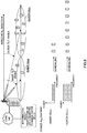
- the number of user terminals connected to the inner cell and the number of user terminals connected to the outer cell vary in proportion (that is, when the proportion of connecting user terminals varies)
- resources that can be allocated to one user terminal also vary between the inner cell and the outer cell.
- the number of user terminals that are present in the coverage area of the inner cell is two (the connecting proportion is 2/10)
- the number of user terminals that are present in the coverage area of the outer cell is eight (the connecting proportion is 8/10).
- the number of resources that can be allocated to one user terminal in the inner cell is greater than the number of resources that can be allocated to one user terminal in the outer cell. In this case, it may occur that resources to allocate to the user terminals of the inner cell are superabundant, and resources to allocate to the user terminals of the outer cell run short. As a result, it becomes difficult to make effective use of radio resources in the inner cell and the outer cell.
- the number of user terminals that are present in the coverage area of the innermost cell (cell #K(N-1)+1) is one (the connecting proportion is 1/M)
- the number of user terminals that are present in the coverage area of the second outermost cell (cell #K+1) is four (the connecting proportion is 4/M)
- the number of user terminals that are present in the coverage area of the outermost cell (cell #1) is two (the connecting proportion is 2/M).
- N is the number of vertical sectors
- K is the number of horizontal sectors
- M is the total number of user terminals per horizontal sector.
- the present inventors have come up with the idea that it is possible to make effective use of radio resources in VSEC by changing the antenna gain, beam width and so on, on a per cell basis, and controlling coverage areas based on the communication capacity of each of a plurality of cells (for example, the number of user terminals that are present in each cell, the number of active users, or statistics of these), or by controlling the resources for each cell by controlling the increase/decrease of power in each cell or executing ON/OFF control, by synchronizing the antenna gain, beam width or tilt angle on a per cell basis.
- each cell's coverage area control and resource allocation control are carried out based on each cell's communication capacity
- the present embodiment is by no means limited to this. It is equally possible to design the coverage area control and resource allocation control for each cell by using, as evaluation indicators, the number of active users in each cell, the amount of resources consumed in each cell, the throughput of each cell, statistics given by statistically calculating and processing these, values given by mathematically calculating these based on design values, and values predicted from past statistics and system simulations, and so on.
- a radio base station When the coverage areas of cells are controlled separately based on the number of user terminals that are present in each cell, a radio base station first acquires information about the number of user terminals present in each cell. This information is converted into data of the proportion of connecting user terminals per cell (the number of user terminals connected to each cell/the total number of user terminals connected to all cells). Information about the number of user terminals that are present in each cell can be acquired, for example, from system information that is output from the network side.
- the number of user terminals connected to each cell can be determined in various other methods. For example, the number of user terminals present in each cell may be calculated based on the assumption that the user terminals are distributed uniformly over the area where each cell is formed. In this case, the number of user terminals that are connected to each cell is calculated depending on the area of each cell.
- radio base stations for example, the place where each cell is formed, and so on
- values given by calculating the number of user terminals taking into account the conditions of design of the radio base stations (for example, the place where each cell is formed, and so on), or values given by predicting the number of user terminals from past statistics, system simulations and so on.
- the conditions in which radio base stations are provided match the surrounding environment such as the positions where the radio base stations are provided (the height, place and so on), the place where each cell is formed, and so on.
- the radio base station Based on the acquired information about the proportion of connecting user terminals in each cell, the radio base station sets each cell's coverage area conditions (for example, the size of the coverage area) such that differences in the proportion of user terminals connected to each cell are reduced. For example, when the proportion of connecting user terminals in a given cell is lower than the average value of the proportions of connecting user terminals of all cells (that is, the reciprocal of the number of all cells, which is 1/2 in a two-cell configuration), conditions to increase the coverage size are set, and when the proportion of connecting user terminals in a given cell is higher than the average value of the proportions of connecting user terminals of all cells (that is, the reciprocal of the number of all cells, which is 1/2 in a two-cell configuration), conditions to reduce the coverage size are set.
- the proportion of connecting user terminals in a given cell is lower than the average value of the proportions of connecting user terminals of all cells (that is, the reciprocal of the number of all cells, which is 1/2 in a two-cell configuration)
- the conditions of beams to form each cell for example, the tilt angle of each cell, the transmission power of each cell, the antenna gain of each cell, the vertical plane beam width of each cell (HPBW: half-power bandwidth)
- HPBW half-power bandwidth
- a cell where the proportion of connecting user terminals is lower than the average value of the proportions of connecting user terminals of all cells will be defined as a "cell where the proportion of connecting user terminals is low”
- a cell where the proportion of connecting user terminals is higher than the average value of the proportions of connecting user terminals of all cells will be defined as a "cell where the proportion of connecting user terminals is high.”
- the radio base station narrows the vertical plane beam width in cells where the proportion of connecting user terminals is high, in accordance with the proportion of connecting user terminals, and widens the vertical plane beam width of cells where the proportion of connecting user terminals is low, in accordance with the proportion of connecting user terminals (see FIG. 5 ).
- the radio base station determines the offset values of the vertical plane beam widths of the beams forming each cell, based on the proportion of connecting user terminals in each cell, on a per cell basis. Then, based on the determined offset values, weights (phase and amplitude) to apply to the antenna section are generated, and the vertical plane beam widths of the beams to output are changed by multiplying the transmission signals by the weights.
- FIG. 5 shows, for example, a case of control in a two-cell configuration, and a case where a user terminal connected to an outer cell is connected to an inner cell by widening the vertical plane beam width of the inner cell in accordance with the proportion of connecting user terminals and by narrowing the vertical plane beam width of the outer cell in accordance with the proportion of connecting user terminals.
- the proportion of connecting user terminals becomes even between cells, and therefore it is possible to allocate resources to the user terminals in each cell evenly. As a result, it is possible to use radio resources without unevenness between user terminals.
- the radio base station can repeat the process of re-acquiring information about the number of user terminals present in each cell and re-setting the coverage areas by changing the vertical plane beam width of each cell in the same way as described above.
- the process of setting the coverage areas of cells it is possible to make the differences in the number of user terminals between cells even smaller, and allow optimization so that radio resources are used without unevenness between user terminals.
- the vertical plane beam width offset values it is possible to prepare various combinations of amounts of offset in a database and determine predetermined offset values in accordance with the proportion of connecting user terminal in each cell.
- the database in which amounts of offset are defined can be prepared based on information that is acquired earlier in other radio base stations, values calculated based on simulation, and so on.
- the radio base station may control the coverage areas of cells not only by changing the vertical plane beam width but also by changing the horizontal plane beam width.
- the radio base station may control the coverage areas of cells not only by changing the vertical plane beam width but also by changing the horizontal plane beam width.
- the radio base station When the coverage area of each cell is controlled by changing transmission power (power), the radio base station lowers the transmission power of cells where the proportion of connecting user terminals is high in accordance with the proportion of connecting user terminals, and increases the transmission power of cells where the proportion of connecting user terminals is low in accordance with the proportion of connecting user terminals (see FIG. 6 ). To be more specific, the radio base station determines the transmission power offset value for each cell based on the proportion of connecting user terminals in each cell. Then, the input signals to each beam are changed on the basis of the determined offset value.
- FIG. 6 shows, as an example, a case of control in a two-cell configuration, where a user terminal connected to an outer cell is connected to an inner cell by increasing the transmission power of the inner cell in accordance with the proportion of connecting user terminals, and by lowering the transmission power of the outer cell in accordance with the proportion of connecting user terminals.
- the proportion of connecting user terminals becomes even between cells, so that it is possible to allocate resources to user terminals in each cell evenly.
- the radio base station can re-acquire information about the number of user terminals present in each cell, and change the transmission power of each cell in the same way as described above.
- the radio base station can re-acquire information about the number of user terminals present in each cell, and change the transmission power of each cell in the same way as described above.
- the transmission power offset values it is possible to prepare various combinations of amounts of offset in a database, and determine predetermined offset values in accordance with the proportion of connecting user terminals in each cell.
- the database in which amounts of offset are defined can be prepared based on information that is acquired earlier in other radio base stations, values calculated based on simulation, and so on.
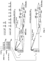
- FIG. 7 shows an example of control where the number of vertical sectors is N and the number of horizontal sectors is K (for example, the case of FIG. 2B ).
- the vertical plane beam width and/or transmission power are controlled so that the coverage areas of cells where the proportion of connecting user terminals is low (#K(N-1)+1 and #1) become bigger, and the vertical plane beam width and/or transmission power are controlled so that the coverage area of a cell where the proportion of connecting user terminals is high (cell #K+1) becomes smaller.
- the radio base station When the resource allocation for each cell is controlled based on the number of user terminals that are present in each cell, the radio base station first acquires information about the number of user terminals that are present in each cell. This information is converted into data of the proportion of user terminals connected to each cell (the number of user terminals connected to each cell/the total number of user terminals in all cells). The information about the proportion of connecting user terminals is acquired in various methods such as ones described above.
- the radio base station changes the amount of (power) resources to allocate to each cell in accordance with the acquired information about the proportion of connecting user terminals. To be more specific, the amount of (power) resources to allocate to cells where the proportion of connecting user terminals is low is set low in accordance with the proportion of connecting user terminals. The amount of (power) resources to allocate to cells where the proportion of connecting user terminals is high is set large in accordance with the proportion of connecting user terminals.
- the radio base station outputs the beams to form each cell and allocate resources to the user terminals present in each cell based on the conditions of the amount of (power) resources to allocate to each cell.
- FIG. 8 shows, as an example, an example of control in a two-cell configuration, and a case where the radio base station reduces the amount of (power) resources to allocate to a cell where the proportion of connecting user terminals is low, and increases the amount of (power) resources to allocate to a cell where the proportion of connecting user terminals is high.
- the amount of (power) resources in each cell is determined in accordance with the proportion of connecting user terminals, it is possible to control the amount of (power) resources to allocate per user terminal in each cell is controlled to be equal. By this means, it is possible to allow optimization so that radio resources are used without unevenness between user terminals.
- FIG. 9 shows a case where the amount of (power) resources to allocate to each cell is controlled in proportion with the proportion of connecting user terminals (a case where 1 ⁇ K/M is allocated to cell #K(N-1)+1, 4 ⁇ K/M is allocated to cell #K+1, and 2 ⁇ K/M is allocated to cell #1).
- the frequency band may be divided and resources may be allocated in accordance with the proportion of connecting user terminals, or time may be divided and resources to match the proportion of connecting user terminals may be allocated, or, it is equally possible to combine these and allocate resources to match the proportion of connecting user terminals, so that it is possible to allow optimization in which radio resources are used without unevenness between user terminals.
- FIG. 10 shows, an example of control in a two-cell configuration, and shows an example of resource allocation control for a cell where the proportion of connecting user terminals is low and a cell where the proportion of connecting user terminals is high.
- FIG. 10A shows a state before the resource allocation control.
- FIG. 10B shows a case where allocation is controlled in the frequency domain (frequency allocation control). In this case, resources are allocated to the cell where the proportion of connecting user terminals is low (the inner cell in FIG. 10 ), limited to a frequency range narrower than before the resource allocation control is executed, in accordance with the proportion of connecting user terminals. Meanwhile, to the cell where the proportion of connecting user terminals is high (the outer cell in FIG. 10 ), resources are allocated by using a wider frequency range than before the resource allocation control, in accordance with the proportion of connecting user terminals.
- FIG. 10C shows a case where allocation is controlled in the time domain.
- the time period to allocate resources is made smaller than before the resource allocation control.
- the time period to allocate resources is made larger than before the resource allocation control (time allocation control).
- a time period t 1 in which resources are allocated to the cell where the proportion of connecting user terminals is high (the outer cell in FIG. 10 and FIG. 11 ), and in which resources are not allocated to the cell where the proportion of connecting user terminals is low (the inner cell in FIG. 10 and FIG. 11 ), is provided periodically. Also, in this time period t 1 , it is preferable to increase the transmission power relatively in the cell where the proportion of connecting user terminals is high.
- time period t 1 when user terminals (UE #1 and UE #2) are present in the inner cell and user terminals (UE #3 to UE #10) are present in the outer cell, in time period t 1 , resources are allocated selectively to the cell where the proportion of connecting user terminals is high (the outer cell in FIG. 11 ), and also the power is increased.
- time period t 1 interference from the cell where the proportion of connecting user terminals is low against the cell where the proportion of connecting user terminals is high is reduced, and furthermore it is possible to allocate more resources to the cell where the proportion of connecting user terminals is high.
- FIG. 12 shows a case where frequency allocation control and time allocation control are executed in accordance with the proportion of connecting user terminals (a case where 1 ⁇ K/Ms is allocated to cell #K(N-1)+1, 4 ⁇ K/M is allocated to cell #K+1, and 2 ⁇ K/M is allocated to cell #1).
- time period t 1 in which resources are not allocated to cell #K+1 and cell #1 and in which resources are allocated selectively to cell #K(N-1)+1, is provided.
- time period t 1 in which resources are allocated selectively to the cell where the proportion of connecting user terminals is high, resources are not allocated to the cell where the proportion of connecting user terminals is low. Consequently, in time period t 1 , it is also possible to change the tilt angles, vertical plane beam widths and/or antenna gains of the cells such that the coverage area of the cell where the proportion of connecting user terminals is high overlaps the coverage area of the cell where the connecting proportion is low (see FIG. 11 ).
- control is designed such that the coverage area of the cell where the proportion of connecting user terminals is high (the outer cell in FIG. 11 ) expands in the direction toward the coverage area of another cell formed in time period t 2 apart from time period t 1 (which, in FIG. 11 , is the inner cell where the proportion of connecting user terminals is low).
- the radio base station apparatus changes the tilt angles, vertical plane beam widths and/or antenna gains of the beam to form the cell where the proportion of connecting user terminals is high (for example, in the case of a two-cell configuration, increases the tilt angle of the outer cell).
- it is possible to reduce interference against other cells that neighbor the cell where the beam is changed.
- FIG. 13 when three or more cells are vertically sectorized, it is possible to change the coverage area of a cell where the proportion of connecting user terminals is high to overlap the coverage area of a cell where the connecting proportion is low, in time period t 1 .
- time period t 1 in which resources are allocated selectively to the cell where the proportion of connecting user terminals is high (cell #K+1), control is designed so that the coverage area of cell #K(N-1)+1 expands in the direction of the coverage area of cell #1.
- UE #M-2 in FIG. 13 a user terminal located on a cell edge (UE #M-2 in FIG. 13 ) is not influenced by cell #1, so that it is preferable to allocate resources to this user terminal.
- FIG. 14 shows a case to provide time period t 3 , in which the radio base station selectively allocates resources to a cell where the proportion of connecting user terminals is low (the inner cell in FIG. 14 ), and expands the coverage area of a cell where the proportion of connecting user terminals is low in this time period t 3 (range expansion).
- the radio base station acquires information about the proportion of connecting user terminals in each cell. Also, the radio base station selects, from among the user terminals that are present in the coverage area of a cell where the proportion of connecting user terminals is high (for example, the outer cell in the two-cell configuration of FIG. 14 ) (UEs #3 to #10), predetermined user terminals (in FIG. 14 , UEs #3 to #5) that can connect with a cell where the proportion of connecting user terminals is low (for example, the inner cell in the two-cell configuration of FIG. 14 ) with predetermined quality or above.
- time period t 3 is periodically provided, in which the radio base station allocates resources to the cell where the proportion of connecting user terminals is low and does not allocate resources to the cell where the proportion of connecting user terminals is high. Furthermore, in this time period t 3 , the radio base station connects predetermined user terminals (UEs #3 to #5) to the cell where the proportion of connecting user terminals is low, and allocates resources from the cell where the proportion of connecting user terminals is low.
- UEs #3 to #5 predetermined user terminals
- the coverage area of the cell where the proportion of connecting user terminals is low may be changed.
- a time period to allocate resources selectively to the cell where the proportion of connecting user terminals is low it is possible to change the tilt angle and/or the vertical plane beam width of the beam to form the cell where the proportion of connecting user terminals is low such that the coverage area of the cell where the proportion of connecting user terminals is low expands in the direction of the coverage area of a cell where the proportion of connecting user terminals is high, formed in time period t 4 apart from this time period t 3 .
- time period t 3 in which resources are selectively allocated to the cell where the proportion of connecting user terminals is low it is possible to reduce interference against other cells that neighbor the cell where the proportion of connecting user terminals is low, and also improve communication quality for predetermined user terminals (UEs #3 to #5). Also, it becomes possible to allocate resources to the user terminals in each cell more evenly, so that effective use of radio resources is made possible.
- FIG. 15 shows a case where time period t 3 , in which resources are selectively allocated to cells where the proportion of connecting user terminals is low (cell #K(N-1)+1 and cell #1), is provided, and the coverage area is expanded (range expansion) in this time period t 3 .
- the radio base station makes a predetermined user terminal (UE #2) connect with a cell where the proportion of connecting user terminals is low (cell #K(N-1)+1) and makes a user terminal (UE #M-2) connect with cell #1, and allocate resources.
- UE #2 predetermined user terminal
- UE #M-2 user terminal
- the radio communication system has a radio base station that can form a plurality of beams that are vertically sectorized, and a user terminal that establishes wireless connection in cells formed by this radio base station, as described above.
- the radio base station has an antenna that outputs a plurality of beams to sectorize a plurality of cells vertically.
- an antenna of this kind there is an array antenna that is formed with a plurality of antenna elements.
- FIG. 16A is a conceptual diagram of an array antenna.
- an array antenna 10 is formed with a plurality of antenna elements 11 that are aligned in a line in one direction.
- sixteen antenna elements 11 are shown as an example.
- the array antenna 10 is formed with a polarized antenna that is a combination of a vertically polarized antenna 10a and a horizontally polarized antenna 10b.
- the antennas that are applicable to the radio base station according to the present embodiment are by no means limited to this antenna configuration. Also, not only vertically polarized and horizontally polarized antennas, but also plus/minus 45-degree polarized antenna elements or an array antenna formed with antenna elements tilting these may be used as well.
- FIG. 16B is a conceptual diagram showing the vertically polarized antenna 10a alone
- FIG. 16C is a conceptual diagram showing the horizontally polarized antenna 10b alone.
- the individual antenna elements 11 are each formed with a set of vertically polarized elements 11V and horizontally polarized elements 11H.
- the radio base station is able to provide a plurality of communication types by using the above array antenna formed with a plurality of antenna elements.
- a first communication type to a third communication type will be described as examples of a plurality of communication types which are applicable to the radio base station.
- the first communication type is a type to form one antenna branch with the whole antenna, by forming one group A with all of the antenna elements 11 constituting the array antenna 10.
- the second communication type is a type to form two antenna branches with the whole antenna, by forming two groups B1 and B2, which divide the array antenna 10 vertically into two.
- the third communication type is a type to form four antenna branches, by forming four groups C1, C2, C3 and C4, which divide the array antenna 10 vertically into four.
- the length of antennas to constitute one branch is the longest (that is, the number of antenna elements is the largest) with the first communication type.
- the length of antennas per branch becomes shorter as the number of antenna branches increases (the number of antenna elements decreases).
- the whole antenna is formed with one antenna branch, so that the antenna gain is maximized, and therefore it is possible to form sharp beams that are directed toward cell edges.
- the number of antenna elements per branch is half, so that, compared to the first communication type, the antenna gain decreases and furthermore the beam width becomes greater.
- the number of antenna elements per branch decreases to 1/2 again from the second communication type, so that, compared to the second communication type, the antenna gain decreases and furthermore the beam width becomes greater.
- the present embodiment is not limited to the above first communication type to the third communication type, it is possible to adequately set an arbitrary number of communication types in accordance with the number of divisions of the antenna elements 11 forming the array antenna 10 in vertical directions. Also, the maximum number of branches can be selected as adequate, depending on the antenna elements 11. Also, the radio communication system according to the present embodiment is able to switch the branch configuration of the array antenna 10 depending on weight.
- FIG. 17 is a diagram to explain the configuration of the radio communication system 1 having the mobile station 100 and radio base station 200 according to an embodiment of the present invention.
- the radio communication system 1 shown in FIG. 17 is a system to accommodate, for example, the LTE system or SUPER 3G.
- this radio communication system 1 may be referred to as "IMT-Advanced” or may be referred to as "4G.”
- the radio communication system 1 is configured to include a radio base station 200 and a plurality of mobile stations 100 (100 1 , 100 2 , 100 3 , ..., 100 n , where n is an integer to satisfy n>0) that communicate with this radio base station 200.
- the radio base station 200 is connected with a higher station apparatus 300, and this higher station apparatus 300 is connected with a core network 400.
- the mobile stations 100 communicate with the radio base station 200 in a cell 500.
- the higher station apparatus 300 may be, for example, an access gateway apparatus, a radio network controller (RNC), a mobility management entity (MME) and so on, but is by no means limited to these.
- RNC radio network controller
- MME mobility management entity
- the mobile stations (100 1 , 100 2 , 100 3 , ..., 100 n ) have the same configuration, functions and state, and therefore will be described simply as "mobile station 100," unless specified otherwise. Also, although the mobile station 100 will be described to perform radio communication with the radio base station 200 for ease of explanation, more generally, user equipment (UE) to include both mobile terminal apparatuses and fixed terminal apparatuses may be used as well.
- UE user equipment
- OFDMA Orthogonal Frequency Division Multiple Access
- SC-FDMA Single-Carrier Frequency Division Multiple Access
- OFDMA is a multi-carrier transmission scheme to perform communication by dividing a frequency band into a plurality of narrow frequency bands (subcarriers) and mapping data to each subcarrier.
- SC-FDMA is a single carrier transmission scheme to reduce interference between terminals by dividing, per terminal, the system band into bands formed with one or continuous resource blocks, and allowing a plurality of terminals to use mutually different bands.
- a PDSCH which is used by each mobile station 100 on a shared basis, and downlink L1/L2 control channels (PDCCH, PCFICH, PHICH), are used.
- PDCH downlink L1/L2 control channels
- PCFICH PCFICH
- PHICH downlink L1/L2 control channels
- a PUSCH which is used by each mobile station 100 on a shared basis
- a PUCCH which is an uplink control channel
- User data is transmitted by means of this PUSCH.
- downlink radio quality information CQI: Channel Quality Indicator
- CQI Channel Quality Indicator
- FIG. 18 is a block diagram to show a configuration of the radio base station 200 according to the present embodiment.
- FIG. 19 is block diagram to show a configuration of an antenna section 230.
- FIG. 20 is a block diagram to show a configuration of the mobile station 100 according to the present embodiment. Note that the configurations of the radio base station 200, antenna section 230 and mobile station 100 shown in FIG. 18 to FIG. 20 are simplified to explain the present invention, and are assumed to have configurations which a radio base station, an antenna section and a mobile station should normally have.
- the radio base station 200 shown in FIG. 18 has, for example, cell control section #1 (hereinafter referred to as the "first cell control section") that controls the radio communication in the first cell in a two-cell configuration (for example, the inner cell), cell control section #2 (hereinafter referred to as the "second cell control section") that controls the radio communication in the second cell (for example, the outer cell), and an antenna section 230 that outputs the beams to form each cell.
- the radio base station 200 according to the present embodiment is not limited to a two-cell configuration, and may assume configurations with three or more cells.
- radio base station 200 shown in FIG. 18 is a radio base station that controls the vertical plane beam width of each cell as described above.
- the radio base station 200 has a communication capacity information acquiring section 231 that acquires information about the communication capacity of each cell (for example, the proportion of connecting user terminals in each cell).
- the communication capacity information acquiring section 231 can acquire information about the number of user terminals present in each cell based on, for example, system information reported from a higher station apparatus and so on.
- the communication capacity information acquiring section 231 acquires information about the number of user terminals that are present in each cell, and then converts the acquired information into data of the proportion of connecting user terminals connected to each cell.
- the communication capacity information acquiring section 231 can acquire the number of user terminals to be connected to each cell in various other methods besides actually counting the number of user terminals that connect with each cell and perform radio communication.
- the number of user terminals present in each cell may be calculated based on the assumption that the user terminals are distributed evenly over the area where each cell is formed.
- the offset amount determining section 232 determines the offset values for changing the vertical plane beam widths of the beams forming the inner cell and the outer cell, based on the information acquired in the communication capacity information acquiring section 231. To be more specific, the offset amount determining section 232 determines the vertical plane beam widths and/or the transmission power offset values of the beams forming each cell based on the proportion of connecting user terminals in each cell, on a per cell basis, and outputs the determined offset values to a vertical weight generating section 233.
- the offset amount determining section 232 may prepare various combinations of amounts of offset in a database and determine predetermined offset values in accordance with the proportion of connecting user terminals in each cell.
- the database to define the amount of offset may be built based on information that has been acquired earlier in other radio base stations or values that are calculated based on simulation.
- the vertical weight generating section 233 generates vertical weights (phase and amplitude) to apply in the antenna section 230, based on the offset values determined in the offset amount determining section 232.
- the vertical weights generated in the vertical weight generating section 233 are output to the antenna section 230, and, in the antenna section 230, transmission signals are multiplied by the weights, thereby controlling the vertical plane beam widths of the beams to be output from the antenna section 230.
- a scheduler may control the resources to allocate to each cell based on the information acquired in the communication capacity information acquiring section 231.
- FIG. 18 shows a configuration to provide a communication capacity information acquiring section 231, an offset amount determining section 232, and a vertical weight generating section 233 for each of the first cell control section and the second cell control section, this is by no means limiting.
- a configuration may be possible in which at least one of the communication capacity information acquiring section 231, the offset amount determining section 232, and the vertical weight generating section 233 (for example, the communication capacity information acquiring section 231 and the offset amount determining section 232) is provided for control sections for a plurality of cells (in FIG. 18 , the first cell control section and the second cell control section) on a shared basis.
- a scheduler determines the number of users to multiplex (the number of users multiplexed) based on channel estimation values given from channel estimation sections 215 #1 to 215 #K, which will be described later. Then, the content of uplink and downlink resource allocation (scheduling information) for each user is determined, and transmission data #1 to #K for users #1 to #K are output to corresponding channel coding sections 201 #1 to 201 #K.
- the transmission data is subjected to channel coding in channel coding sections 201 #1 to 201 #K, and, after that, output to data modulation sections 202 #1 to 202 #K and subjected to data modulation.
- the channel coding and data modulation are executed based on channel coding rates and modulation schemes given from MIMO switching sections 221 #1 to 221 #K, which will be described later.
- Transmission data #1 to #K subjected to data modulation in data modulation sections 202 #1 to 202 #K are converted from time sequence signals to frequency domain signals through a discrete Fourier transform in an unillustrated discrete Fourier transform section, and output to a subcarrier mapping section 203.
- the subcarrier mapping section 203 maps transmission data #1 to #K to subcarriers in accordance with resource allocation information given from a resource allocation control section 220, which will be described later.
- the subcarrier mapping section 203 maps (multiplexes) reference signals #1 to #K input from an unillustrated reference signal generating section and broadcast information and system information input from a broadcast information generating section and a system information generating section, to subcarriers, with transmission data #1 to #K. In this way, transmission data #1 to #K mapped to the subcarriers are output to precoding multiplication sections 204 #1 to 204 #K.
- Precoding multiplication sections 204 #1 to 204 #K apply a phase and/or amplitude shift to transmission data #1 to #K, for each of antenna elements #1 to #N, based on precoding weights given from a precoding weight control section 219, which will be described later (weighting of antenna elements #1 to #N by precoding).
- Transmission data #1 to #K, to which a phase and/or amplitude shift has been applied by precoding multiplication sections 204 #1 to 204 #K, are output to a multiplexer (MUX) 205.
- MUX multiplexer
- transmission data #1 to #K having been subjected to a phase and/or amplitude shift, are synthesized to generate transmission signals for each of antenna elements #1 to #N.
- the transmission signals generated in the multiplexer (MUX) 205 are converted from frequency domain signals to time domain signals through an inverse fast Fourier transform in inverse fast Fourier transform sections (IFFT) 206 #1 to 206 #N. Then, after CPs are added in cyclic prefix (CP) adding sections 207 #1 to 207 #N, the signals are output to the antenna section 230.
- IFFT inverse fast Fourier transform
- CPs cyclic prefix
- transmission signals that are transmitted from the mobile station 100 on the uplink are received in the antenna section 230, and converted from radio frequency signals into baseband signals through frequency conversion.
- the baseband signals subjected to frequency conversion have the CPs removed in CP removing sections 211 #1 to 211 #N, and output to fast Fourier transform sections (FFT sections) 212 #1 to 212 #N.
- FFT sections fast Fourier transform sections
- FFT sections 212 #1 to 212 #N perform a Fourier transform of the input received signals, and convert the signals from time sequence signals to frequency domain signals.
- the received signals having been converted to frequency domain signals are output to data channel signal separation sections 214 #1 to 214 #K.
- Data channel signal separation sections 214 #1 to 214 #K separate the received signals input from FFT sections 212 #1 to 212 #N, by, for example, minimum mean squared error (MMSE) and maximum likelihood detection (MLD) signal separation methods. By this means, the received signals having arrived from the mobile station 100 are separated into received signals pertaining to user terminal #1 to user terminal #K.
- MMSE minimum mean squared error
- MLD maximum likelihood detection
- Channel estimation sections 215 #1 to 215 #K estimate channel states from the reference signals included in the received signals separated in data channel signal separation sections 214 #1 to 214 #K, and report the estimated channel states to control channel demodulation sections 216 #1 to 216 #K.
- the received signals pertaining to user terminal #1 to user terminal #K, separated in data channel signal separation sections 214 #1 to 214 #K, are demapped in an unillustrated subcarrier demapping section and converted back to time sequence signals, and then demodulated in data demodulation sections 217 #1 to 217 #K.
- Control channel demodulation sections 216 #1 to 216 #K demodulate the control channel signals (for example, the PUCCH) included in the received signals separated in data channel signal separation sections 214 #1 to 214 #K. At this time, in control channel demodulation sections 216 #1 to 216 #K, the control channel signals corresponding to user terminal #1 to user terminal #K are demodulated based on the channel states reported from channel estimation sections 215 #1 to 215 #K. The control channel signals demodulated in control channel demodulation sections 216 #1 to 216 #K are output to CSI information updating sections 218 #1 to 218 #K.
- control channel signals for example, the PUCCH
- CSI information updating sections 218 #1 to 218 #K extract channel state information (CSI) included in each control channel signal (for example, the PUCCH) or shared data channel signal (PUSCH) input from control channel demodulation sections 216 #1 to 216 #K, so that CSI is always updated to the latest state.
- the CSI includes PMIs, RIs and CQIs.
- the CSI information updated in CSI information updating sections 218 #1 to 218 #K is output to the precoding weight control section 219, the resource allocation control section 220 and MIMO switching sections 221 #1 to 221 #K.
- the precoding weight control section 219 Based on beam selection information and the CSI information input from CSI information updating sections 218 #1 to 218 #K, the precoding weight control section 219 generates precoding weights to represent the amounts of phase and/or amplitude shift for transmission data #1 to #K.
- the generated precoding weights are output to precoding multiplication sections 204 #1 to 204 #K, and are used in the precoding of transmission data #1 to transmission data #K.
- the resource allocation control section 220 determines the resource allocation information to allocate to each user.
- MIMO switching sections 221 #1 to 221 #K select the MIMO transmission schemes to use for transmission data #1 to transmission data #K, based on the CSI information input from CSI information updating sections 218 #1 to 218 #K. Then, the channel coding rates and modulation schemes for transmission data #1 to transmission data #K to match the selected MIMO transmission schemes are determined. The determined channel coding rates are output to channel coding sections 201 #1 to 201 #K, and the determined modulation schemes are output to the data modulation sections 202 #1 to 202 #K.
- the antenna section 230 has a plurality of antenna elements 250, an RF phase/amplitude adjusting circuit 249, and a vertical weight multiplication section 240, and so on.
- signals that are output from the CP adding sections 207 of the first cell control section and the second cell control section are input in the vertical weight multiplication section 240. Also, information about the vertical weights generated in the vertical weight generating sections 233 of the first cell control section and the second cell control section is also input in the vertical weight multiplication section 240.
- the vertical weight multiplication section 240 signals from the first cell control section and the second cell control section are branched via dividers 241 #1 and 241 #2, and are output to phase/amplitude adjustors 243 corresponding to each of a plurality of antenna elements 250.
- the vertical weight multiplication section 240 multiplies the vertical weights so that the offset values (here, vertical plane beam width offset values) determined in the offset amount determining section 232 are implemented, in the phase/amplitude adjustors 243.
- the transmission signals in the first cell (for example, the inner cell) and the second cell (for example, the outer cell), output from the vertical weight multiplication section 240, are synthesized in a synthesizer 244 and then output to the RF phase/amplitude adjusting circuit 249 via a DA converter 245, an up-converter 246, and a duplexer 247.
- the RF phase/amplitude adjusting circuit 249 adjusts the directions of the beams to form the first cell and the second cell, and furthermore carries out calibration between the branches. Signals output from the RF phase/amplitude adjusting circuit 249 are output via the antenna elements 250.
- transmission signals transmitted from the mobile station 100 on the uplink are received in antenna elements 250, and then output to the duplexer 247 via the RF phase/amplitude adjusting circuit 249.
- the transmission signals are separated into the transmitting path and the receiving path in the duplexer 247, and then output to a divider 252 via a down-converter 248 and an AD converter 251.
- the signals are branched into the signals of the first cell and the second cell, and then output to synthesizers 242 #1 and 242 #2 via the phase/amplitude adjustors 243 of the vertical weight multiplication section 240.
- synthesizers 242 #1 and 242 #2 of the vertical weight multiplication section 240 the received signals received in the antenna elements 250 are synthesized for each of the first cell and the second cell, and output to the first cell control section and the second cell control section.
- transmission signals output from the radio base station 200 are received by transmitting/receiving antennas TRX #1 to TRX #N, separated into the transmitting path and the receiving path in duplexers 101 #1 to 101 #N, and then output to RF receiving circuits 102 #1 to 102 #N. Then, in RF receiving circuits 102 #1 to 102 #N, the radio frequency signals are converted into baseband signals through frequency conversion.
- the baseband signals have the CPs removed in cyclic prefix (CP) removing sections 103 #1 to 103 #N, and are output to fast Fourier transform sections (FFT sections) 104 #1 to 104 #N.
- a receiving timing estimation section 105 estimates the receiving timing from the reference signals included in the received signals, and reports the estimated results to CP removing sections 103 #1 to 103 #N.
- FFT sections 104 #1 to 104 #N perform a Fourier transform on the received signals that are received as input, and convert the time sequence signals into frequency domain signals.
- the received signals, having been converted into frequency domain signals, are output to a data channel signal separation section 106.
- the data channel signal separation section 106 separates the received signals input from FFT sections 104 #1 to 104 #N by, for example, minimum mean square error (MMSE) and maximum likelihood detection (MLD) signal separation methods.
- MMSE minimum mean square error
- MLD maximum likelihood detection
- a channel estimation section 107 estimates the channel states from the reference signals included in the received signals separated in the data channel signal separation section 106, and reports the estimated channel states to a control channel demodulation section 108.
- the received signal pertaining to user terminal #K, separated in the data channel signal separation section 106, is demapped in a subcarrier demapping section, which is not shown, converted back to a time sequence signal, and then demodulated in a data demodulation section 109. Then, as channel decoding is executed in a channel decoding section, which is not shown, transmission signal #K is reconstructed.
- the control channel demodulation section 108 demodulates the control channel signal (for example, the PDCCH) included in the received signal separated in the data channel signal separation section 106. When this takes place, the control channel demodulation section 108 demodulates the control channel signal corresponding to user terminal #K, based on the channel state reported from the channel estimation section 107.
- the control channel signals demodulated by the control channel demodulation section 108 are output to a channel quality measurement section 110.
- the channel quality measurement section 110 measures channel quality (CQIs) based on the control channel signals received as input from the control channel demodulation section 108. Also, the channel quality measurement section 110 selects PMIs and RIs based on the measured CQIs. Then, CSI (CQIs, PMIs and RIs) or RSRP is reported to a CSI feedback signal generating section 111 and a MIMO switching section 112.
- CQIs channel quality
- the CSI feedback signal generating section 111 CSI feedback signals to feed back to the radio base station 200 are generated.
- the CQIs, PMIs and RIs reported from the channel quality measurement section 110 are included in the CSI feedback signals.
- the feedback signals (CSI feedback or RSRP feedback) generated in the CSI feedback signal generating section 111 are output to a multiplexer (MUX) 113.
- MUX multiplexer
- the MIMO switching section 112 selects the MIMO transmission scheme to use for transmission data #K. Then, the channel coding rate and modulation scheme for transmission data #K, to match the selected MIMO transmission scheme, are determined. The determined channel coding rates are output to a channel coding section 114, and the determined modulation schemes are output to a data modulation section 115.
- transmission data #K pertaining to user #K, transmitted from a higher layer is subjected to channel coding by the channel coding section 114, and then subjected to data modulation in the data modulation section 115.
- Transmission data #K, having been subjected to data modulation in the data modulation section 115, is converted from a time sequence signal to a frequency domain signal in a serial-to-parallel conversion section, which is not shown, and output to a subcarrier mapping section 116.
- the subcarrier mapping section 116 maps transmission data #K to subcarriers in accordance with schedule information that is designated from the radio base station 200. At this time, the subcarrier mapping section 116 maps (multiplexes) reference signal #K, generated in a reference signal generating section (not shown), to the subcarriers with transmission data #K. Transmission data #K mapped to subcarriers in this way is output to a precoding multiplication section 117.
- the precoding multiplication section 117 applies a phase and/or amplitude shift to transmission data #K, for each of transmitting/receiving antennas TRX #1 to TRX #N. Then, the precoding multiplication section 117 applies a phase and/or amplitude shift in accordance with the precoding weights that correspond to the PMIs that are designated by the control channel signals demodulated in the control channel demodulation section 108. Transmission data #K, having been subjected to a phase and/or amplitude shift by the precoding multiplication section 117, is output to the multiplexer (MUX) 113.
- MUX multiplexer
- the multiplexer (MUX) 113 synthesizes transmission data #K, to which a phase and/or amplitude shift has been applied, with the control signals generated in the CSI feedback signal generating section 111, and generates transmission signals for each of transmitting/receiving antennas TRX #1 to TRX #N.
- the transmission signals generated in the multiplexer (MUX) 113 are converted from frequency domain signals to time domain signals through an inverse fast Fourier transform in inverse fast Fourier transform sections 118 #1 to 118 #N, and then have CPs added in CP adding sections 119 #1 to 119 #N, and are output to RF transmitting circuits 120 #1 to 120 #N.
- the signals are output to transmitting/receiving antennas TRX #1 to TRX #N via duplexers 101 #1 to 101 #N, and output from transmitting/receiving antennas TRX #1 to TRX #N to the radio base station 200 on the uplink.
- the configurations of the radio base station 200 that are applicable with the present embodiment are not limited to the configuration shown in above FIG. 18 .
- the configuration of the antenna section 230 is also not limited to the configuration shown in FIG. 19 .
- a configuration may be possible in which the vertical weight multiplication section 240 is provided in the inner cell control section and the outer cell control section. Examples of the configurations of the radio base station 200 and the antenna section 230 in this case will be described with reference to FIG. 21 to FIG. 23 . Note that descriptions of parts that overlap with above FIG. 18 and FIG. 19 will be omitted.
- the radio base station 200 shown in FIG. 21 has transmitting vertical weight multiplication sections 236 #1 to #K that multiply transmitting/received signals by vertical weights in the first cell control section and the second cell control section, and receiving vertical weight multiplication sections 235 #1 to #K.
- vertical weights that are generated in the vertical weight generating section 233 are controlled in a weight switching section 234, and output to transmitting vertical weight multiplication sections 236 #1 to #K and receiving vertical weight multiplication sections 235 #1 to #K.
- the weight switching section 234 controls and switches between a plurality of weights output from the vertical weight generating section 233 per predetermined period, and outputs the vertical weights generated in the vertical weight generating section 233 to transmitting vertical weight multiplication sections 236 #1 to #K and receiving vertical weight multiplication sections 235 #1 to #K.
- the control is executed in the weight switching section 234.
- the weight switching section 234 determines the length of time to allocate to t 1 and t 2 or to t 3 and t 4 such that resources are allocated adequately (for example, evenly) to each user terminal.
- the weight switching section 234 designs control such that, together with each user terminal's scheduling information allocated in the subcarrier mapping section 203, and in coordination with the passage of the above time period, a plurality of weights output from the vertical weight generating section 233 are switched and output to transmitting vertical weight multiplication sections 236 #1 to #K.
- information about the transmission timing of the mobile station and so on determined based on the length of time allocated to t 1 and t 2 or to t 3 and t 4 is reported from the radio base station to the mobile station by means of broadcast information.
- Each user terminal receives the signals transmitted from the radio base station normally, and, meanwhile, as for the transmission timing, controls the transmission schedule in accordance with the transmission timing reported from the radio base station by means of broadcast information.
- the radio base station then designs control such that, in coordination with the above time period, a plurality of weights output from the vertical weight generating section 233 are switched and output to receiving vertical weight multiplication sections 235 #1 to #K, thereby receiving the signals from each mobile station with coordinated timing.
- FIG. 22 shows a block diagram of the transmitting vertical weight multiplication section 236.
- signals output from the precoding multiplication section 204 are branched in a divider 261, and output to phase/amplitude adjustors 263 corresponding to a plurality of antenna elements 250.
- phase/amplitude adjustors 263 weights that are generated in the vertical weight generating section 233 are multiplied on the signals.
- the receiving vertical weight multiplication section 235 synthesizes these in a synthesizer 262, and output the result to a data channel signal separation section 214.
- the antenna section 230 may assume a configuration removing the vertical weight multiplication section 240 from the configuration shown in FIG. 19 , as shown in FIG. 23 .
Landscapes
- Engineering & Computer Science (AREA)
- Computer Networks & Wireless Communication (AREA)
- Signal Processing (AREA)
- Mobile Radio Communication Systems (AREA)
- Radio Transmission System (AREA)
Claims (5)
- Funkkommunikationsverfahren für eine Funkbasisstation (200), die eine Vielzahl von Strahlen mit variierenden Neigungswinkeln ausgibt und eine Vielzahl von Zellen bildet, die mittels der Vielzahl von Strahlen mit variierenden Neigungswinkeln in eine Vielzahl von Sektoren unterteilt ist, und ein Benutzerendgerät, das eine drahtlose Verbindung mit der Funkbasisstation (200) herstellt, wobei das Funkkommunikationsverfahren die folgenden Schritte umfasst, bei denen:die Funkbasisstation (200):einen Bewertungsindikator betreffend eine Menge von Verkehr jeder der Vielzahl von Zellen erfasst; unddie Menge an Frequenz- und/oder Zeitressourcen zum Zuweisen an eine Zelle, die einen relativ geringen Bewertungsindikator unter der Vielzahl von Zellen aufweist, geringer einstellt als für eine Zelle, die einen relativ hohen Bewertungsindikator aufweist,wobei die Funkbasisstation (200) eine Zeitperiode bereitstellt, um der Zelle, die den relativ hohen Bewertungsindikator aufweist, Ressourcen zuzuweisen und der Zelle, die den relativ niedrigen Bewertungsindikator aufweist, keine Ressourcen zuzuweisen, und in dieser Zeitperiode die Übertragungsleistung der Zelle, die den relativ hohen Bewertungsindikator aufweist, zu erhöhen,wobei in der Zeitperiode die Funkbasisstation (200) einen Neigungswinkel des Strahls ändert, der die Zelle bildet, die den relativ hohen Bewertungsindikator aufweist, sodass sich eine Reichweite der Zelle, die den relativ hohen Bewertungsindikator aufweist, in einer Richtung der Reichweite der Zelle, die den relativ niedrigen, Bewertungsindikator aufweist, der außerhalb der Zeitperiode gebildet wird, ausweitet.
- Funkkommunikationsverfahren nach Anspruch 1, wobei die Funkbasisstation (200) einen Frequenzbereich zum Zuweisen von Ressourcen an eine Zelle, die einen relativ niedrigen Bewertungsindikator unter der Vielzahl von Zellen aufweist, und/oder eine Zeitperiode zum Zuweisen von Ressourcen schmaler macht als für die Zelle, die einen relativ hohen Bewertungsindikator aufweist.
- Funkkommunikationsverfahren für eine Funkbasisstation (200), die eine Vielzahl von Strahlen mit variierenden Neigungswinkeln ausgibt und eine Vielzahl von Zellen bildet, die mittels der Vielzahl von Strahlen mit variierenden Neigungswinkeln in eine Vielzahl von Sektoren unterteilt ist, und ein Benutzerendgerät, das eine drahtlose Verbindung mit der Funkbasisstation (200) herstellt, wobei das Funkkommunikationsverfahren die folgenden Schritte umfasst, bei denen:
die Funkbasisstation (200):einen Bewertungsindikator betreffend eine Menge von Verkehr jeder der Vielzahl von Zellen erfasst;ein vorbestimmtes Benutzerendgerät auswählt, das sich mit einer Zelle verbinden kann, die einen relativ niedrigen Bewertungsindikator mit vorbestimmter Qualität oder darüber unter den Benutzerendgeräten aufweist, die in einer Reichweite einer Zelle vorhanden sind, die einen relativ hohen Bewertungsindikator aus der Vielzahl von Zellen aufweist; undeine Zeitperiode bereitstellt, um der Zelle, die den relativ niedrigen Bewertungsindikator aufweist, Ressourcen zuzuweisen und der Zelle, die den relativ hohen Bewertungsindikator aufweist, keine Ressourcen zuzuweisen, und in der Zeitperiode Ressourcen dem vorbestimmten Benutzerendgerät von der Zelle zuweist, die den relativ niedrigen Bewertungsindikator aufweist,wobei in der Zeitperiode die Funkbasisstation (200) einen Neigungswinkel eines Strahls ändert, um die Zelle zu bilden, die den relativ niedrigen Bewertungsindikator aufweist, sodass sich eine Reichweite der Zelle, die den relativ niedrigen Bewertungsindikator aufweist, in einer Richtung der Reichweite der Zelle, die den relativ hohen Bewertungsindikator aufweist, der außerhalb der Zeitperiode gebildet wird, ausweitet. - Funkbasisstation (200), die eine Vielzahl von Zellen bildet, wobei die Funkbasisstation (200) umfasst:einen Antennenabschnitt (230), der zum Ausgeben einer Vielzahl von Strahlen mit variierenden Neigungswinkeln und zum Bilden einer Vielzahl von Zellen, die mittels der Vielzahl von Strahlen mit variierenden Neigungswinkeln in eine Vielzahl von Sektoren unterteilt wird, konfiguriert ist;einen Informationserfassungsabschnitt (231), der zum Erfassen eines Bewertungsindikators betreffend eine Menge von Verkehr jeder der Vielzahl von Zellen konfiguriert ist; undeinen Steuerabschnitt, der zum Steuern eines Neigungswinkels eines Strahls, einer Vertikalebenen-Strahlbreite und/oder Übertragungsleistung jeder Zelle konfiguriert ist und eine Reichweite jeder Zelle so einstellt, dass Differenzen im Bewertungsindikator zwischen der Vielzahl von Zellen reduziert werden,wobei die Funkbasisstation (200) eine Zeitperiode bereitstellt, um der Zelle, die den relativ hohen Bewertungsindikator aufweist, Ressourcen zuzuweisen und der Zelle, die den relativ niedrigen Bewertungsindikator aufweist, keine Ressourcen zuzuweisen, und in dieser Zeitperiode die Übertragungsleistung der Zelle, die den relativ hohen Bewertungsindikator aufweist, zu erhöhen,wobei in der Zeitperiode die Funkbasisstation (200) einen Neigungswinkel des Strahls ändert, der die Zelle bildet, die den relativ hohen Bewertungsindikator aufweist, sodass sich eine Reichweite der Zelle, die den relativ hohen Bewertungsindikator aufweist, in einer Richtung der Reichweite der Zelle, die den relativ niedrigen Bewertungsindikator aufweist, der außerhalb der Zeitperiode gebildet wird, ausweitet.
- Funkkommunikationssystem, umfassend eine Funkbasisstation (200), die eine Vielzahl von Zellen bildet, die mittels der Vielzahl von Strahlen mit variierenden Neigungswinkeln in eine Vielzahl von Sektoren unterteilt ist, und ein Benutzerendgerät, das eine drahtlose Verbindung mit der Funkbasisstation (200) herstellt, wobei die Funkbasisstation (200) umfasst:einen Antennenabschnitt (230), der zum Ausgeben einer Vielzahl von Strahlen variierender Neigungswinkel und zum Bilden einer Vielzahl von Zellen konfiguriert ist;einen Informationserfassungsabschnitt, der zum Erfassen eines Bewertungsindikators betreffend eine Menge von Verkehr jeder der Vielzahl von Zellen konfiguriert ist; undeinen Steuerabschnitt, der zum Steuern eines Neigungswinkels eines Strahls, einer Vertikalebenen-Strahlbreite und/oder Übertragungsleistung jeder Zelle konfiguriert ist und eine Reichweite jeder Zelle so einstellt, dass Differenzen im Bewertungsindikator zwischen der Vielzahl von Zellen reduziert werden,wobei die Funkbasisstation (200) eine Zeitperiode bereitstellt, um der Zelle, die den relativ hohen Bewertungsindikator aufweist, Ressourcen zuzuweisen und der Zelle, die den relativ niedrigen Bewertungsindikator aufweist, keine Ressourcen zuzuweisen, und in dieser Zeitperiode die Übertragungsleistung der Zelle, die den relativ hohen Bewertungsindikator aufweist, zu erhöhen,wobei in der Zeitperiode die Funkbasisstation (200) einen Neigungswinkel des Strahls ändert, der die Zelle bildet, die den relativ hohen Bewertungsindikator aufweist, sodass sich eine Reichweite der Zelle, die den relativ hohen Bewertungsindikator aufweist, in einer Richtung der Reichweite der Zelle, die den relativ niedrigen Bewertungsindikator aufweist, der außerhalb der Zeitperiode gebildet wird, ausweitet.
Applications Claiming Priority (2)
| Application Number | Priority Date | Filing Date | Title |
|---|---|---|---|
| JP2012081085A JP6053305B2 (ja) | 2012-03-30 | 2012-03-30 | 無線基地局、無線通信システム及び無線通信方法 |
| PCT/JP2013/053031 WO2013145885A1 (ja) | 2012-03-30 | 2013-02-08 | 無線基地局、無線通信システム及び無線通信方法 |
Publications (3)
| Publication Number | Publication Date |
|---|---|
| EP2833662A1 EP2833662A1 (de) | 2015-02-04 |
| EP2833662A4 EP2833662A4 (de) | 2015-12-16 |
| EP2833662B1 true EP2833662B1 (de) | 2018-08-01 |
Family
ID=49259170
Family Applications (1)
| Application Number | Title | Priority Date | Filing Date |
|---|---|---|---|
| EP13770028.2A Not-in-force EP2833662B1 (de) | 2012-03-30 | 2013-02-08 | Drahtlose basisstation, drahtloses kommunikationssystem und drahtloses kommunikationsverfahren |
Country Status (4)
| Country | Link |
|---|---|
| US (1) | US9439198B2 (de) |
| EP (1) | EP2833662B1 (de) |
| JP (1) | JP6053305B2 (de) |
| WO (1) | WO2013145885A1 (de) |
Families Citing this family (26)
| Publication number | Priority date | Publication date | Assignee | Title |
|---|---|---|---|---|
| WO2014146700A1 (en) * | 2013-03-19 | 2014-09-25 | Nokia Solutions And Networks Oy | Methods and apparatus for antenna tilt optimization |
| US20140295869A1 (en) * | 2013-03-31 | 2014-10-02 | Tejas Networks Limited | Method and System of creating virtual sector within physical sector to avoid the interference and maximize the system throughput |
| JP6673824B2 (ja) * | 2013-11-04 | 2020-04-01 | エルジー エレクトロニクス インコーポレイティド | 無線通信システムにおいて信号を送信する方法及び装置 |
| JP6244868B2 (ja) * | 2013-12-10 | 2017-12-13 | 富士通株式会社 | 基地局 |
| US10327156B2 (en) * | 2014-07-15 | 2019-06-18 | Lg Electronics Inc. | Resource allocation method and signal processing method of terminal |
| JP6301766B2 (ja) * | 2014-07-25 | 2018-03-28 | 株式会社東芝 | 通信制御装置および通信制御システム |
| JP2016046750A (ja) * | 2014-08-26 | 2016-04-04 | 富士通株式会社 | 制御装置、送信電力制御方法、及び、無線通信システム |
| KR101555020B1 (ko) | 2014-09-29 | 2015-09-22 | 고려대학교 산학협력단 | 이동통신 서비스를 제공하는 시스템 및 이동통신 서비스 방법 |
| JP6580833B2 (ja) * | 2015-01-23 | 2019-09-25 | Kddi株式会社 | 制御装置、制御方法、及びコンピュータプログラム |
| JP6487221B2 (ja) * | 2015-01-23 | 2019-03-20 | Kddi株式会社 | 制御装置、制御方法、及びコンピュータプログラム |
| KR101620956B1 (ko) * | 2015-01-28 | 2016-05-16 | 고려대학교 산학협력단 | 멀티캐스트 전송 스케줄링 방법 |
| CN106160801B (zh) * | 2015-03-25 | 2020-01-31 | 联想(北京)有限公司 | 一种信号处理方法及基站 |
| WO2016167447A1 (ko) * | 2015-04-17 | 2016-10-20 | 엘지전자 주식회사 | 무선 통신 시스템에서의 동기 신호 송수신 방법 |
| US20180294859A1 (en) | 2015-10-07 | 2018-10-11 | Intel IP Corporation | Dynamically beamformed control channel for beamformed cells |
| CN115955261B (zh) | 2015-10-12 | 2026-01-06 | 诺基亚技术有限公司 | 在蜂窝系统中的发现信号传输 |
| JP6559626B2 (ja) * | 2016-08-23 | 2019-08-14 | 日本電信電話株式会社 | 無線回線割当方法および無線通信装置 |
| CN109997316B (zh) * | 2016-12-02 | 2022-05-03 | 夏普株式会社 | 基站装置、通信系统、波束控制方法以及计算机可读取的记录介质 |
| WO2019072392A1 (en) * | 2017-10-12 | 2019-04-18 | Telefonaktiebolaget Lm Ericsson (Publ) | BEAM FORMATION FOR SYNCHRONIZATION SIGNALS |
| KR102469563B1 (ko) * | 2017-10-17 | 2022-11-22 | 삼성전자주식회사 | 무선 통신 시스템에서 송신 전력을 제어하기 위한 장치 및 방법 |
| US10892814B2 (en) * | 2018-12-07 | 2021-01-12 | Charter Communications Operating, Llc | Performing receive beamforming in a fifth generation millimeter wave system |
| JP7081555B2 (ja) * | 2019-04-02 | 2022-06-07 | 日本電信電話株式会社 | 置局支援方法および置局支援システム |
| CN110191510B (zh) * | 2019-04-03 | 2022-10-25 | 中国联合网络通信集团有限公司 | 波束分配方法及装置 |
| US10716015B1 (en) * | 2019-07-08 | 2020-07-14 | Sprint Communications Company L.P. | Broadcast beam profile assignment |
| CN112953608B (zh) * | 2019-12-11 | 2026-04-07 | 中兴通讯股份有限公司 | 一种信号的发送、处理方法及装置 |
| US12207243B2 (en) * | 2020-10-30 | 2025-01-21 | Qualcomm Incorporated | Techniques for separated beam design |
| US11342973B1 (en) * | 2021-10-19 | 2022-05-24 | King Faisal University | System and method for maintaining link communications in millimeter wave cellular networks |
Citations (1)
| Publication number | Priority date | Publication date | Assignee | Title |
|---|---|---|---|---|
| EP0531090A2 (de) * | 1991-09-03 | 1993-03-10 | Nippon Telegraph And Telephone Corporation | Zellen-Wiederholungsmuster in einem Mobil-Kommunikationssystem |
Family Cites Families (30)
| Publication number | Priority date | Publication date | Assignee | Title |
|---|---|---|---|---|
| US6246674B1 (en) * | 1997-01-27 | 2001-06-12 | Metawave Communications Corporation | Antenna deployment sector cell shaping system and method |
| US7493143B2 (en) * | 2001-05-07 | 2009-02-17 | Qualcomm Incorporated | Method and system for utilizing polarization reuse in wireless communications |
| JP2004072663A (ja) * | 2002-08-09 | 2004-03-04 | Fujitsu Ltd | アンテナ制御装置 |
| US7437166B2 (en) * | 2003-09-24 | 2008-10-14 | Telefonaktiebolaget Lm Ericsson (Publ) | Reducing shared downlink radio channel interference by transmitting to multiple mobiles using multiple antenna beams |
| DE602006017810D1 (de) * | 2006-05-12 | 2010-12-09 | Alcatel Lucent | Resourcenzuweisung für eine OFDM Übertragung mit Susch zwischen Basisstationen |
| JP4808651B2 (ja) * | 2007-03-02 | 2011-11-02 | Kddi株式会社 | 基地局装置およびセル構成方法 |
| JP5152472B2 (ja) * | 2007-04-28 | 2013-02-27 | 日本電気株式会社 | 無線通信システムにおけるリソース割当制御方法および装置 |
| US7706323B2 (en) * | 2007-05-02 | 2010-04-27 | Alvarion Ltd. | Wireless communications in a multi-sector network |
| EP2166782A1 (de) * | 2007-07-10 | 2010-03-24 | Panasonic Corporation | Funkkommunikations-basisstationsvorrichtung, funkkommunikations-endgerät und funkkommunikationsverfahren |
| KR20090041323A (ko) * | 2007-10-23 | 2009-04-28 | 엘지전자 주식회사 | 데이터 블록 구성함에 있어서 단말의 식별 정보를 효과적으로 전송하는 방법 |
| JP5056858B2 (ja) * | 2007-10-31 | 2012-10-24 | 日本電気株式会社 | 通信システムにおけるリソース割当方法及びリソース割当システム並びにそれに用いる基地局 |
| US8150399B2 (en) * | 2007-12-21 | 2012-04-03 | Intel Corporation | Techniques for wireless communications networks employing beamforming |
| JP5088149B2 (ja) * | 2008-01-17 | 2012-12-05 | 富士通株式会社 | スケジューリング方法及び無線基地局 |
| EP2242296A4 (de) * | 2008-04-02 | 2016-03-30 | Nec Corp | Steuervorrichtung, kommunikationssystem, ressourcenzuteilung und aufzeichnungsmedium, das ein entsprechendes programm beinhaltet |
| KR20100046338A (ko) * | 2008-10-27 | 2010-05-07 | 삼성전자주식회사 | 이동통신 시스템의 공조 빔 형성 장치 및 방법 |
| US8374135B2 (en) * | 2008-11-13 | 2013-02-12 | Nec Laboratories America, Inc. | Methods and systems for location-based allocation of macro cell resources |
| US8682326B2 (en) * | 2008-12-23 | 2014-03-25 | Telefonaktiebolaget Lm Ericsson (Publ) | Base station and method for vertical tilt antenna beam sweeping |
| JPWO2010110396A1 (ja) * | 2009-03-26 | 2012-10-04 | 京セラ株式会社 | アンテナ制御装置、無線通信システム及びアンテナ制御方法 |
| US20120020431A1 (en) * | 2009-04-16 | 2012-01-26 | Nec Corporation | Antenna device and multi-antenna system |
| JP2011019039A (ja) * | 2009-07-08 | 2011-01-27 | Nec Corp | 基地局制御法、基地局、および基地局制御装置 |
| EP2296394B1 (de) * | 2009-09-10 | 2016-08-10 | Alcatel Lucent | Basisstation, Verfahren und Computerprogrammprodukt zum Belastungsausgleich in einer Gruppe von Funkfeststationen |
| KR101555820B1 (ko) * | 2009-12-02 | 2015-10-06 | 삼성전자주식회사 | 접속망의 클래스에 따라 비대칭적인 피드백 기법을 사용하는 계층 셀 통신 시스템 |
| JP5496707B2 (ja) | 2010-02-26 | 2014-05-21 | 株式会社日立製作所 | 海水淡水化装置 |
| JP2012054736A (ja) * | 2010-09-01 | 2012-03-15 | Hitachi Ltd | 移動体通信システムおよび移動体通信システムにおける負荷分散方法 |
| US9936490B2 (en) * | 2010-09-03 | 2018-04-03 | Panasonic Intellectual Property Corporation Of America | Wireless communication system, low transmission power cell base station, macrocell base station, wireless terminal, and load distribution method |
| JP4923161B1 (ja) * | 2010-09-29 | 2012-04-25 | シャープ株式会社 | 移動通信システム、移動局装置、基地局装置、通信方法および集積回路 |
| EP2747304A4 (de) | 2011-08-15 | 2015-02-18 | Ntt Docomo Inc | Drahtlose basisstation, benutzerendgerät, drahtloses kommunikationssystem und drahtloses kommunikationsverfahren |
| US9094977B2 (en) * | 2011-11-11 | 2015-07-28 | Samsung Electronics Co., Ltd. | Apparatus and method for supporting mobility management in communication systems with large number of antennas |
| US9749935B2 (en) * | 2012-03-09 | 2017-08-29 | Samsung Electronics Co., Ltd. | Methods and apparatus for cell scanning in system with large number of antennas |
| US9173200B2 (en) * | 2013-02-28 | 2015-10-27 | Intel Mobile Communications GmbH | Communication terminal, network component, base station and method for communicating |
-
2012
- 2012-03-30 JP JP2012081085A patent/JP6053305B2/ja not_active Expired - Fee Related
-
2013
- 2013-02-08 EP EP13770028.2A patent/EP2833662B1/de not_active Not-in-force
- 2013-02-08 WO PCT/JP2013/053031 patent/WO2013145885A1/ja not_active Ceased
- 2013-02-08 US US14/387,383 patent/US9439198B2/en not_active Expired - Fee Related
Patent Citations (1)
| Publication number | Priority date | Publication date | Assignee | Title |
|---|---|---|---|---|
| EP0531090A2 (de) * | 1991-09-03 | 1993-03-10 | Nippon Telegraph And Telephone Corporation | Zellen-Wiederholungsmuster in einem Mobil-Kommunikationssystem |
Also Published As
| Publication number | Publication date |
|---|---|
| EP2833662A1 (de) | 2015-02-04 |
| US20150094076A1 (en) | 2015-04-02 |
| JP2013211716A (ja) | 2013-10-10 |
| JP6053305B2 (ja) | 2016-12-27 |
| US9439198B2 (en) | 2016-09-06 |
| EP2833662A4 (de) | 2015-12-16 |
| WO2013145885A1 (ja) | 2013-10-03 |
Similar Documents
| Publication | Publication Date | Title |
|---|---|---|
| EP2833662B1 (de) | Drahtlose basisstation, drahtloses kommunikationssystem und drahtloses kommunikationsverfahren | |
| US9680537B2 (en) | Radio base station, user terminal, radio communication system and radio communication method | |
| US9379793B2 (en) | Radio communication system, radio base station apparatus, user terminal and radio communication method | |
| US10721692B2 (en) | Radio communication method, local area base station apparatus, mobile terminal apparatus and radio communication system | |
| JP6224880B2 (ja) | 基地局装置、ユーザ端末、通信システム及び通信制御方法 | |
| EP2749080B1 (de) | Verfahren und zentrale basisstation zur interferenzverwaltung in einem zellularen netzwerk | |
| US8787261B2 (en) | Base station apparatus, mobile station apparatus and transmission power control method | |
| EP3073665B1 (de) | Methode zur anordnung von referenzsignalen und drahtlose kommunikationsbasisstationsvorrichtung | |
| EP3179651A1 (de) | Basisstationsvorrichtung, benutzerendgerät, kommunikationssystem und kommunikationssteuerungsverfahren | |
| US9236937B2 (en) | Radio base station and communication control method including downlink radio resource allocation | |
| WO2014077742A1 (en) | Methods and apparatus for reference signal antenna mapping configuration | |
| KR102078616B1 (ko) | 빔포밍 통신 시스템에서 빔 간섭을 고려한 자동 이득 제어 및 빔 스케줄링 방법 및 이를 위한 장치 | |
| JP2018029375A (ja) | 基地局装置、ユーザ端末及び通信制御方法 | |
| JP2018078593A (ja) | 基地局装置、ユーザ端末及び無線通信方法 | |
| KR102449735B1 (ko) | 다중 안테나 통신 시스템에서 파일롯을 전송하는 방법 및 장치, 그리고 다중 안테나 통신 시스템에서 파일롯을 할당하는 방법 및 장치 | |
| Sheikh et al. | Performance analysis of dual-cell HSDPA plus MIMO and LTE along with adaptive MIMO switching at the cellular level |
Legal Events
| Date | Code | Title | Description |
|---|---|---|---|
| PUAI | Public reference made under article 153(3) epc to a published international application that has entered the european phase |
Free format text: ORIGINAL CODE: 0009012 |
|
| 17P | Request for examination filed |
Effective date: 20141015 |
|
| AK | Designated contracting states |
Kind code of ref document: A1 Designated state(s): AL AT BE BG CH CY CZ DE DK EE ES FI FR GB GR HR HU IE IS IT LI LT LU LV MC MK MT NL NO PL PT RO RS SE SI SK SM TR |
|
| AX | Request for extension of the european patent |
Extension state: BA ME |
|
| DAX | Request for extension of the european patent (deleted) | ||
| RA4 | Supplementary search report drawn up and despatched (corrected) |
Effective date: 20151117 |
|
| RIC1 | Information provided on ipc code assigned before grant |
Ipc: H04B 7/10 20060101ALI20151111BHEP Ipc: H04W 16/28 20090101ALI20151111BHEP Ipc: H04J 99/00 20090101ALI20151111BHEP Ipc: H04W 88/08 20090101ALI20151111BHEP Ipc: H04J 11/00 20060101ALI20151111BHEP Ipc: H04W 16/08 20090101AFI20151111BHEP Ipc: H04B 7/06 20060101ALI20151111BHEP |
|
| STAA | Information on the status of an ep patent application or granted ep patent |
Free format text: STATUS: EXAMINATION IS IN PROGRESS |
|
| 17Q | First examination report despatched |
Effective date: 20170517 |
|
| GRAP | Despatch of communication of intention to grant a patent |
Free format text: ORIGINAL CODE: EPIDOSNIGR1 |
|
| STAA | Information on the status of an ep patent application or granted ep patent |
Free format text: STATUS: GRANT OF PATENT IS INTENDED |
|
| INTG | Intention to grant announced |
Effective date: 20180326 |
|
| GRAS | Grant fee paid |
Free format text: ORIGINAL CODE: EPIDOSNIGR3 |
|
| GRAA | (expected) grant |
Free format text: ORIGINAL CODE: 0009210 |
|
| STAA | Information on the status of an ep patent application or granted ep patent |
Free format text: STATUS: THE PATENT HAS BEEN GRANTED |
|
| AK | Designated contracting states |
Kind code of ref document: B1 Designated state(s): AL AT BE BG CH CY CZ DE DK EE ES FI FR GB GR HR HU IE IS IT LI LT LU LV MC MK MT NL NO PL PT RO RS SE SI SK SM TR |
|
| REG | Reference to a national code |
Ref country code: GB Ref legal event code: FG4D |
|
| REG | Reference to a national code |
Ref country code: CH Ref legal event code: EP Ref country code: AT Ref legal event code: REF Ref document number: 1025807 Country of ref document: AT Kind code of ref document: T Effective date: 20180815 |
|
| REG | Reference to a national code |
Ref country code: IE Ref legal event code: FG4D |
|
| REG | Reference to a national code |
Ref country code: DE Ref legal event code: R096 Ref document number: 602013041238 Country of ref document: DE |
|
| REG | Reference to a national code |
Ref country code: NL Ref legal event code: MP Effective date: 20180801 |
|
| REG | Reference to a national code |
Ref country code: LT Ref legal event code: MG4D |
|
| REG | Reference to a national code |
Ref country code: AT Ref legal event code: MK05 Ref document number: 1025807 Country of ref document: AT Kind code of ref document: T Effective date: 20180801 |
|
| PG25 | Lapsed in a contracting state [announced via postgrant information from national office to epo] |
Ref country code: LT Free format text: LAPSE BECAUSE OF FAILURE TO SUBMIT A TRANSLATION OF THE DESCRIPTION OR TO PAY THE FEE WITHIN THE PRESCRIBED TIME-LIMIT Effective date: 20180801 Ref country code: PL Free format text: LAPSE BECAUSE OF FAILURE TO SUBMIT A TRANSLATION OF THE DESCRIPTION OR TO PAY THE FEE WITHIN THE PRESCRIBED TIME-LIMIT Effective date: 20180801 Ref country code: SE Free format text: LAPSE BECAUSE OF FAILURE TO SUBMIT A TRANSLATION OF THE DESCRIPTION OR TO PAY THE FEE WITHIN THE PRESCRIBED TIME-LIMIT Effective date: 20180801 Ref country code: BG Free format text: LAPSE BECAUSE OF FAILURE TO SUBMIT A TRANSLATION OF THE DESCRIPTION OR TO PAY THE FEE WITHIN THE PRESCRIBED TIME-LIMIT Effective date: 20181101 Ref country code: AT Free format text: LAPSE BECAUSE OF FAILURE TO SUBMIT A TRANSLATION OF THE DESCRIPTION OR TO PAY THE FEE WITHIN THE PRESCRIBED TIME-LIMIT Effective date: 20180801 Ref country code: NL Free format text: LAPSE BECAUSE OF FAILURE TO SUBMIT A TRANSLATION OF THE DESCRIPTION OR TO PAY THE FEE WITHIN THE PRESCRIBED TIME-LIMIT Effective date: 20180801 Ref country code: FI Free format text: LAPSE BECAUSE OF FAILURE TO SUBMIT A TRANSLATION OF THE DESCRIPTION OR TO PAY THE FEE WITHIN THE PRESCRIBED TIME-LIMIT Effective date: 20180801 Ref country code: IS Free format text: LAPSE BECAUSE OF FAILURE TO SUBMIT A TRANSLATION OF THE DESCRIPTION OR TO PAY THE FEE WITHIN THE PRESCRIBED TIME-LIMIT Effective date: 20181201 Ref country code: RS Free format text: LAPSE BECAUSE OF FAILURE TO SUBMIT A TRANSLATION OF THE DESCRIPTION OR TO PAY THE FEE WITHIN THE PRESCRIBED TIME-LIMIT Effective date: 20180801 Ref country code: GR Free format text: LAPSE BECAUSE OF FAILURE TO SUBMIT A TRANSLATION OF THE DESCRIPTION OR TO PAY THE FEE WITHIN THE PRESCRIBED TIME-LIMIT Effective date: 20181102 Ref country code: NO Free format text: LAPSE BECAUSE OF FAILURE TO SUBMIT A TRANSLATION OF THE DESCRIPTION OR TO PAY THE FEE WITHIN THE PRESCRIBED TIME-LIMIT Effective date: 20181101 |
|
| PG25 | Lapsed in a contracting state [announced via postgrant information from national office to epo] |
Ref country code: LV Free format text: LAPSE BECAUSE OF FAILURE TO SUBMIT A TRANSLATION OF THE DESCRIPTION OR TO PAY THE FEE WITHIN THE PRESCRIBED TIME-LIMIT Effective date: 20180801 Ref country code: HR Free format text: LAPSE BECAUSE OF FAILURE TO SUBMIT A TRANSLATION OF THE DESCRIPTION OR TO PAY THE FEE WITHIN THE PRESCRIBED TIME-LIMIT Effective date: 20180801 Ref country code: AL Free format text: LAPSE BECAUSE OF FAILURE TO SUBMIT A TRANSLATION OF THE DESCRIPTION OR TO PAY THE FEE WITHIN THE PRESCRIBED TIME-LIMIT Effective date: 20180801 |
|
| PG25 | Lapsed in a contracting state [announced via postgrant information from national office to epo] |
Ref country code: ES Free format text: LAPSE BECAUSE OF FAILURE TO SUBMIT A TRANSLATION OF THE DESCRIPTION OR TO PAY THE FEE WITHIN THE PRESCRIBED TIME-LIMIT Effective date: 20180801 Ref country code: IT Free format text: LAPSE BECAUSE OF FAILURE TO SUBMIT A TRANSLATION OF THE DESCRIPTION OR TO PAY THE FEE WITHIN THE PRESCRIBED TIME-LIMIT Effective date: 20180801 Ref country code: EE Free format text: LAPSE BECAUSE OF FAILURE TO SUBMIT A TRANSLATION OF THE DESCRIPTION OR TO PAY THE FEE WITHIN THE PRESCRIBED TIME-LIMIT Effective date: 20180801 Ref country code: RO Free format text: LAPSE BECAUSE OF FAILURE TO SUBMIT A TRANSLATION OF THE DESCRIPTION OR TO PAY THE FEE WITHIN THE PRESCRIBED TIME-LIMIT Effective date: 20180801 Ref country code: CZ Free format text: LAPSE BECAUSE OF FAILURE TO SUBMIT A TRANSLATION OF THE DESCRIPTION OR TO PAY THE FEE WITHIN THE PRESCRIBED TIME-LIMIT Effective date: 20180801 |
|
| REG | Reference to a national code |
Ref country code: DE Ref legal event code: R097 Ref document number: 602013041238 Country of ref document: DE |
|
| PG25 | Lapsed in a contracting state [announced via postgrant information from national office to epo] |
Ref country code: DK Free format text: LAPSE BECAUSE OF FAILURE TO SUBMIT A TRANSLATION OF THE DESCRIPTION OR TO PAY THE FEE WITHIN THE PRESCRIBED TIME-LIMIT Effective date: 20180801 Ref country code: SK Free format text: LAPSE BECAUSE OF FAILURE TO SUBMIT A TRANSLATION OF THE DESCRIPTION OR TO PAY THE FEE WITHIN THE PRESCRIBED TIME-LIMIT Effective date: 20180801 Ref country code: SM Free format text: LAPSE BECAUSE OF FAILURE TO SUBMIT A TRANSLATION OF THE DESCRIPTION OR TO PAY THE FEE WITHIN THE PRESCRIBED TIME-LIMIT Effective date: 20180801 |
|
| PLBE | No opposition filed within time limit |
Free format text: ORIGINAL CODE: 0009261 |
|
| STAA | Information on the status of an ep patent application or granted ep patent |
Free format text: STATUS: NO OPPOSITION FILED WITHIN TIME LIMIT |
|
| 26N | No opposition filed |
Effective date: 20190503 |
|
| PG25 | Lapsed in a contracting state [announced via postgrant information from national office to epo] |
Ref country code: SI Free format text: LAPSE BECAUSE OF FAILURE TO SUBMIT A TRANSLATION OF THE DESCRIPTION OR TO PAY THE FEE WITHIN THE PRESCRIBED TIME-LIMIT Effective date: 20180801 |
|
| REG | Reference to a national code |
Ref country code: DE Ref legal event code: R119 Ref document number: 602013041238 Country of ref document: DE |
|
| REG | Reference to a national code |
Ref country code: CH Ref legal event code: PL |
|
| GBPC | Gb: european patent ceased through non-payment of renewal fee |
Effective date: 20190208 |
|
| PG25 | Lapsed in a contracting state [announced via postgrant information from national office to epo] |
Ref country code: LU Free format text: LAPSE BECAUSE OF NON-PAYMENT OF DUE FEES Effective date: 20190208 Ref country code: MC Free format text: LAPSE BECAUSE OF FAILURE TO SUBMIT A TRANSLATION OF THE DESCRIPTION OR TO PAY THE FEE WITHIN THE PRESCRIBED TIME-LIMIT Effective date: 20180801 |
|
| REG | Reference to a national code |
Ref country code: BE Ref legal event code: MM Effective date: 20190228 |
|
| REG | Reference to a national code |
Ref country code: IE Ref legal event code: MM4A |
|
| PG25 | Lapsed in a contracting state [announced via postgrant information from national office to epo] |
Ref country code: LI Free format text: LAPSE BECAUSE OF NON-PAYMENT OF DUE FEES Effective date: 20190228 Ref country code: CH Free format text: LAPSE BECAUSE OF NON-PAYMENT OF DUE FEES Effective date: 20190228 |
|
| PG25 | Lapsed in a contracting state [announced via postgrant information from national office to epo] |
Ref country code: DE Free format text: LAPSE BECAUSE OF NON-PAYMENT OF DUE FEES Effective date: 20190903 Ref country code: GB Free format text: LAPSE BECAUSE OF NON-PAYMENT OF DUE FEES Effective date: 20190208 Ref country code: IE Free format text: LAPSE BECAUSE OF NON-PAYMENT OF DUE FEES Effective date: 20190208 |
|
| PG25 | Lapsed in a contracting state [announced via postgrant information from national office to epo] |
Ref country code: FR Free format text: LAPSE BECAUSE OF NON-PAYMENT OF DUE FEES Effective date: 20190228 Ref country code: BE Free format text: LAPSE BECAUSE OF NON-PAYMENT OF DUE FEES Effective date: 20190228 |
|
| PG25 | Lapsed in a contracting state [announced via postgrant information from national office to epo] |
Ref country code: TR Free format text: LAPSE BECAUSE OF FAILURE TO SUBMIT A TRANSLATION OF THE DESCRIPTION OR TO PAY THE FEE WITHIN THE PRESCRIBED TIME-LIMIT Effective date: 20180801 |
|
| PG25 | Lapsed in a contracting state [announced via postgrant information from national office to epo] |
Ref country code: PT Free format text: LAPSE BECAUSE OF FAILURE TO SUBMIT A TRANSLATION OF THE DESCRIPTION OR TO PAY THE FEE WITHIN THE PRESCRIBED TIME-LIMIT Effective date: 20181201 Ref country code: MT Free format text: LAPSE BECAUSE OF NON-PAYMENT OF DUE FEES Effective date: 20190208 |
|
| PG25 | Lapsed in a contracting state [announced via postgrant information from national office to epo] |
Ref country code: CY Free format text: LAPSE BECAUSE OF FAILURE TO SUBMIT A TRANSLATION OF THE DESCRIPTION OR TO PAY THE FEE WITHIN THE PRESCRIBED TIME-LIMIT Effective date: 20180801 |
|
| PG25 | Lapsed in a contracting state [announced via postgrant information from national office to epo] |
Ref country code: HU Free format text: LAPSE BECAUSE OF FAILURE TO SUBMIT A TRANSLATION OF THE DESCRIPTION OR TO PAY THE FEE WITHIN THE PRESCRIBED TIME-LIMIT; INVALID AB INITIO Effective date: 20130208 |
|
| PG25 | Lapsed in a contracting state [announced via postgrant information from national office to epo] |
Ref country code: MK Free format text: LAPSE BECAUSE OF FAILURE TO SUBMIT A TRANSLATION OF THE DESCRIPTION OR TO PAY THE FEE WITHIN THE PRESCRIBED TIME-LIMIT Effective date: 20180801 |