EP2833681A1 - Procédé et équipement d'utilisateur pour une régulation de la puissance sur la liaison montante - Google Patents
Procédé et équipement d'utilisateur pour une régulation de la puissance sur la liaison montante Download PDFInfo
- Publication number
- EP2833681A1 EP2833681A1 EP20130767652 EP13767652A EP2833681A1 EP 2833681 A1 EP2833681 A1 EP 2833681A1 EP 20130767652 EP20130767652 EP 20130767652 EP 13767652 A EP13767652 A EP 13767652A EP 2833681 A1 EP2833681 A1 EP 2833681A1
- Authority
- EP
- European Patent Office
- Prior art keywords
- uplink
- transmit power
- frame
- prach
- fdma symbols
- Prior art date
- Legal status (The legal status is an assumption and is not a legal conclusion. Google has not performed a legal analysis and makes no representation as to the accuracy of the status listed.)
- Granted
Links
Images



Classifications
-
- H—ELECTRICITY
- H04—ELECTRIC COMMUNICATION TECHNIQUE
- H04W—WIRELESS COMMUNICATION NETWORKS
- H04W52/00—Power management, e.g. Transmission Power Control [TPC] or power classes
- H04W52/04—Transmission power control [TPC]
- H04W52/18—TPC being performed according to specific parameters
- H04W52/24—TPC being performed according to specific parameters using SIR [Signal to Interference Ratio] or other wireless path parameters
- H04W52/248—TPC being performed according to specific parameters using SIR [Signal to Interference Ratio] or other wireless path parameters where transmission power control commands are generated based on a path parameter
-
- H—ELECTRICITY
- H04—ELECTRIC COMMUNICATION TECHNIQUE
- H04W—WIRELESS COMMUNICATION NETWORKS
- H04W52/00—Power management, e.g. Transmission Power Control [TPC] or power classes
- H04W52/04—Transmission power control [TPC]
- H04W52/30—Transmission power control [TPC] using constraints in the total amount of available transmission power
- H04W52/34—TPC management, i.e. sharing limited amount of power among users or channels or data types, e.g. cell loading
- H04W52/346—TPC management, i.e. sharing limited amount of power among users or channels or data types, e.g. cell loading distributing total power among users or channels
-
- H—ELECTRICITY
- H04—ELECTRIC COMMUNICATION TECHNIQUE
- H04W—WIRELESS COMMUNICATION NETWORKS
- H04W52/00—Power management, e.g. Transmission Power Control [TPC] or power classes
- H04W52/04—Transmission power control [TPC]
- H04W52/30—Transmission power control [TPC] using constraints in the total amount of available transmission power
- H04W52/36—Transmission power control [TPC] using constraints in the total amount of available transmission power with a discrete range or set of values, e.g. step size, ramping or offsets
- H04W52/367—Power values between minimum and maximum limits, e.g. dynamic range
-
- H—ELECTRICITY
- H04—ELECTRIC COMMUNICATION TECHNIQUE
- H04W—WIRELESS COMMUNICATION NETWORKS
- H04W52/00—Power management, e.g. Transmission Power Control [TPC] or power classes
- H04W52/04—Transmission power control [TPC]
- H04W52/38—TPC being performed in particular situations
- H04W52/50—TPC being performed in particular situations at the moment of starting communication in a multiple access environment
-
- H—ELECTRICITY
- H04—ELECTRIC COMMUNICATION TECHNIQUE
- H04W—WIRELESS COMMUNICATION NETWORKS
- H04W52/00—Power management, e.g. Transmission Power Control [TPC] or power classes
- H04W52/04—Transmission power control [TPC]
- H04W52/06—TPC algorithms
- H04W52/14—Separate analysis of uplink or downlink
- H04W52/146—Uplink power control
-
- H—ELECTRICITY
- H04—ELECTRIC COMMUNICATION TECHNIQUE
- H04W—WIRELESS COMMUNICATION NETWORKS
- H04W52/00—Power management, e.g. Transmission Power Control [TPC] or power classes
- H04W52/04—Transmission power control [TPC]
- H04W52/30—Transmission power control [TPC] using constraints in the total amount of available transmission power
- H04W52/32—TPC of broadcast or control channels
- H04W52/325—Power control of control or pilot channels
-
- H—ELECTRICITY
- H04—ELECTRIC COMMUNICATION TECHNIQUE
- H04W—WIRELESS COMMUNICATION NETWORKS
- H04W52/00—Power management, e.g. Transmission Power Control [TPC] or power classes
- H04W52/04—Transmission power control [TPC]
- H04W52/30—Transmission power control [TPC] using constraints in the total amount of available transmission power
- H04W52/34—TPC management, i.e. sharing limited amount of power among users or channels or data types, e.g. cell loading
Definitions
- the present invention relates to the field of communications and particularly to an uplink power control method and a user equipment.
- LTE-A Long Term Evolution-Advanced
- Rel-10 Release-10
- LTE-A Long Term Evolution-Advanced
- CA Carrier Aggregation
- uplink transmission timings of the respective carriers are adjusted based on a TA (Time Advance) obtained in the RA (Random Access) procedure on the PCC (Primary Component Carrier), that is, the uplink transmission timings of multiple carriers are aligned, so that such a situation will not occur that an uplink signal in a current uplink sub-frame overlaps in transmission with an uplink signal in an adjacent uplink sub-frame.
- TA Time Advance
- RA Random Access
- uplink out-of-synchronization of the PCC will cause uplink out-of-synchronization of other carriers, and at this time a UE (User Equipment) will obtain a new TA in the RA procedure on the PCC.
- a PUCCH Physical Uplink Control Channel
- PUSCH Physical Uplink Shared Channel
- SRS Sounding Reference Signal
- PRACH Physical Random Access Channel
- the PRACH is used to carry a random access preamble sequence so as to obtain the TA value, and as illustrated in Fig.1 , the preamble sequence is consisted of a CP (Cyclic Prefix) and a sequence, where the length of the CP is T CP , and the length of the sequence is T SEQ .
- a GT Guard Time
- the structure of the PRACH is as illustrated in Fig.2 , where the length of the PRACH is the duration of one TTI (Transmission Time Interval).
- the CP and the GT are used to avoid interference between the PRACH and a previous or succeeding uplink sub-frame, and the values of the CP and the GT reflect the maximal RTD (Round Trip Delay) decided by the cell size and the maximal channel delay spread.
- Table 1 Preamble format T CP T SEQ Number K of sub-frames occupied by PRACH 0 (normal format) for a cell radius of approximately 15km 3168 ⁇ T s 24576 ⁇ T s 1 1 (a long CP) for a cell radius of approximately 30 to 100km (exclusive) 21024 ⁇ T s 24576 ⁇ T s 2 2 (a short CP and a repeated preamble sequence) for a cell radius of approximately 30km 6240 ⁇ T s 2.24576 ⁇ T s 2 3 (a long CP and a repeated preamble sequence) for a cell radius of approximately 100km 21024 ⁇ T s 2 ⁇ 24576 ⁇ T s 3 4 (only applicable to a TDD system) for a hotspot area 448 ⁇ T s 4096 ⁇ T s TDD special sub-frames UpPTS
- the format 4 is specific to the TDD (Time Division Duplexing) system and is used for a hotspot area with the radius of approximately 2 kilometers and transmitted only in an UpPTS (Uplink Pilot Time Slot) configured with two SC-FDMA (Single Carrier-Frequency Division Multiple Access) symbols starting at 4832 T S ahead of the end of an UpPTS sub-frame.
- the configuration of each carrier is decided by the higher layer.
- the PRACH with the transmission length of more than 1ms typically occupies the consecutive uplink sub-frames for transmission.
- target transmit power P PUCCH ( i ) of the PUCCH transmitted on the PCC in an uplink sub-frame i target transmit power P PRACH ( i ) of the PRACH transmitted on the PCC, target transmit power P PUSCH,c ( i ) of the PUSCH transmitted on each carrier and target transmit power P SRS,c ( i ) of the SRS transmitted on each carrier are defined for a CA UE, where c represents the carrier index, and i represents the sub-frame.
- concurrent transmission of the PUCCH and the PUSCH on the same carrier or different carriers is supported in the same uplink sub-frame, and concurrent transmission of the PUSCHs on different carriers is supported in the same uplink sub-frame. If the total transmit power of the UE in the current uplink sub-frame i would exceed the allowed maximum transmit power of the UE, then transmit power of the uplink signals in the uplink sub-frame need to be scaled by the same scaling factor according to the priorities of the uplink signals, that is, the uplink transmit power of the UE is controlled in such a way that the same power scaling factor applies to uplink signals with the same priority of the uplink signals.
- the UE preferentially ensures not to scale down the target transmit power of the PUCCH, and firstly scales down the target transmit power of the PUSCH on each carrier c, so that the sum of the transmit power of all the uplink signals after power scaling does not exceed the allowed maximum transmit power P CMAX ( i ) of the UE, that is: ⁇ c w i ⁇ P ⁇ PUSCH , c i ⁇ P ⁇ CMAX i - P ⁇ PUCCH i
- P ⁇ PUSCH,c ( i ) represents a linear-domain value of P PUSCH,c ( i )
- P ⁇ PUSCH ( i ) represents a linear-domain value of P PUSCH ( i )
- P ⁇ CMAX ( i ) represents a linear-domain value of P CMAX ( i )
- the power scaling factor w ( i ) can be determined firstly if the target transmit power of the PUSCHs needs to be scaled down, and preferably the determined power scaling factor w(i) meets the following condition: the sum of the transmit power of all the uplink signals does not exceed the allowed maximum transmit power P CMAX ( i ) of the UE after the target transmit power of the PUSCHs are scaled down. Then the UE scales down the target transmit power of the PUSCHs according to the determined w ( i ).
- the transmit power of the PUSCH with UCI can be further scaled down.
- CA across different frequency bands in the uplink and a hybrid CA deployment of a macro base station and an RRH (Remote Radio Head) can be supported. Since transmission characteristics and transmission paths of radio signals in the different frequency bands may be different, there may be different uplink transmission delays so that signals on different carriers transmitted in the same uplink sub-frame may arrive at the base station at different times. Therefore the uplink transmission timing of the different carriers may be adjusted by using different TAs in the Rel-11.
- a TA group has been introduced to the LTE-A Rel-11, where carriers with the same or similar transmission delays are considered as one group and referred to as a TA group, the same TA applies to carriers in the same TA group, and a TA value corresponding to the TA group is obtained in the RA procedure on one of carriers in the TA group.
- the uplink synchronization will be achieved by the RA procedure on a predetermined carrier in the TA group.
- the PCC is the carrier on which the RA procedure is performed
- SCCs Secondary Component Carriers
- one of the SCCs can be selected for the RA procedure, so the PRACH transmission on an SCC is supported in the LTE-A Rel-11, and at present it is determined that concurrent transmission of PRACHs on multiple carriers in an uplink sub-frame is not supported.
- a PUCCH/PUSCH or another uplink signal may be transmitted on one or more uplink carriers in another TA group in uplink synchronization, so concurrent transmission of the PRACH and the PUCCH/PUSCH needs to be supported in the LTE-A Rel-11.
- the PUCCH/PUSCH in the uplink sub-frame where it is located may overlap in transmission with the PRACH in all or a part of SC-FDMA symbols.
- the PRACH overlaps in transmission with the PUCCH/PUSCH to ensure the total transmit power of the respective uplink signals not to exceed the allowed maximum transmit power of the UE in the prior art.
- Embodiments of the invention provide an uplink power control method and a user equipment so as to perform uplink power control in the case that a PRACH overlaps in transmission with other uplink signals.
- An uplink power control method includes: a User Equipment (UE) determining target transmit power of uplink signals transmitted on respective synchronized uplink component carriers in a current uplink sub-frame; judging whether a Physical Random Access Channel (PRACH) is transmitted on an uplink secondary component carrier in the current uplink sub-frame; if so, then determining target transmit power of the PRACH and further judging whether a sum of the target transmit power of the uplink signals and the target transmit power of the PRACH would exceed maximum transmit power of the UE; if so, then maintaining the target transmit power of the PRACH unchanged, and scaling down target transmit power of all or a part of Single Carrier-Frequency Division Multiple Access (SC-FDMA) symbols of the uplink signal required to be power scaled-down among the uplink signals in the current uplink sub-frame until a sum of transmit power of the uplink signals in the current uplink sub-frame does not exceed the maximum transmit power of the UE minus the target transmit power of the PRACH.
- SC-FDMA Single Carrier-Freque
- a User Equipment includes: a first transmit power determination unit configured to determine target transmit power of uplink signals transmitted on respective synchronized uplink component carriers in a current uplink sub-frame; a channel judgment unit configured to judge whether a Physical Random Access Channel (PRACH) is transmitted on an uplink secondary component carrier in the current uplink sub-frame; a second transmit power determination unit configured to determine target transmit power of the PRACH when the channel judgment unit judges that the PRACH is transmitted on the uplink secondary component carrier in the current uplink sub-frame; a transmit power judgment unit configured to judge whether a sum of the target transmit power of the uplink signals and the target transmit power of the PRACH would exceed maximum transmit power of the UE; and a power control unit configured to maintain the target transmit power of the PRACH unchanged, and to scale down target transmit power of all or a part of Single Carrier-Frequency Division Multiple Access (SC-FDMA) symbols of an uplink signal required to be power scaled-down among the uplink signals in the current uplink sub-frame until a sum of transmit power of the
- the UE determines target transmit power of uplink signals transmitted on respective synchronized uplink component carriers in a current uplink sub-frame, and judges whether a PRACH is transmitted on an uplink secondary component carrier in the current uplink sub-frame, and if so, then it indicates such a situation that the PRACH overlaps in transmission with the uplink signals occurs, and at this time the UE can determine the target transmit power of the PRACH and further judge whether the sum of the target transmit power of the uplink signals and the target transmit power of the PRACH would exceed the maximum transmit power of the UE, and if so, then the UE maintains the target transmit power of the PRACH unchanged and scales down the target transmit power of all or a part of SC-FDMA symbols of an uplink signal required to be power scaled among the uplink signals in the current uplink sub-frame until the sum of the transmit power of the uplink signals in the current uplink sub-frame does not exceed the maximum transmit power of the UE minus the target transmit power of the PRACH
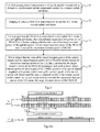
- Fig.3 illustrates a flow chart of an uplink power control method according to the first embodiment of the invention, and the particular process flow thereof is as follows:
- the uplink signals can include, but not be limited to, at least one of the following signals: a PUSCH, a PUCCH and an SRS.
- Step 32 judging whether a PRACH is transmitted on an uplink SCC in the current uplink sub-frame.
- the uplink transmission timing of the different carriers may be adjusted by using different TAs.
- carriers with the same or similar transmission delays are considered as one group and referred to as a TA group, the same TA applies to carriers in the same TA group, and a TA value corresponding to the TA group is obtained in the RA procedure on one of carriers in the TA group.
- the uplink synchronization will be performed in the RA procedure on a predetermined carrier in the TA group to obtain a new TA value.
- the PCC is the carrier on which the RA procedure is performed, and for a TA group including only SCCs, one of the SCCs can be selected for the RA procedure.
- the RA procedure will be triggered on a carrier in the TA group to obtain a new TA. If the TA group includes the PCC at this time, then the PCC will initiate the RA procedure, and no PUCCH/PUSCH/SRS or another uplink signal will be transmitted in the current uplink sub-frame during the RA procedure of the PCC, so such a situation will not occur that a PRACH overlaps in transmission with a PUCCH/PUSCH/SRS or another uplink signal in the current uplink sub-frame.
- the TA group in uplink out-of-synchronization includes no PPC but only SCCs, then one of the SCCs will initiate the RA procedure, and at this time a PUCCH/PUSCH/SRS or another uplink signal may be transmitted concurrently on an uplink component carrier in another TA group in uplink synchronization, and then a PRACH may overlap in transmission with the PUCCH/PUSCH/SRS on all or a part of SC-FDMA symbols.
- Step 33 if it is judged that the PRACH is transmitted on the uplink SCC in the current uplink sub-frame, then determining target transmit power of the PRACH and further judging whether the sum of the target transmit power of the uplink signals and the target transmit power of the PRACH would exceed the maximum transmit power of the UE.
- the UE can perform uplink power control in the following two implementations without any limitation:
- the UE reuses the uplink power control scheme in the LTE-A Rel-10, and specifically, the UE judges whether the sum of the target transmit power of the uplink signals would exceed the maximum transmit power of the UE.
- the UE can scale down the target transmit power of all the SC-FDMA symbols of an uplink signal required to be power scaled-down among the uplink signals in the current uplink sub-frame until the sum of the transmit power of the uplink signals in the current uplink sub-frame does not exceed the maximum transmit power of the UE.
- the uplink signal required to be power scaled is an uplink signal, with non-zero transmit power and the lowest priority, selected from the uplink signals in the current uplink sub-frame according to priorities of the uplink signals.
- the power of multiple uplink signals is scaled down by the same scaling factor until the sum of the transmit power of the uplink signals in the current uplink sub-frame does not exceed the maximum transmit power of the UE; that is, as defined in the Rel-10, the uplink signal priority of a PUCCH is higher than that of a PUSCH with UCI, which is higher than that of a PUSCH without UCI, so firstly the power of the PUSCH without UCI is scaled down, and if the sum of the transmit power of the uplink signals in the current uplink sub-frame would still exceed the maximum transmit power of the UE when the transmit power of the PUSCH without UCI is scaled down to zero, then the transmit power of the PUSCH with UCI is further scaled down,
- power control can be performed in a corresponding power control method for concurrent transmission of an SRS and a PUCCH/PUSCH in the case of multi-TA transmission.
- the UE If it is judged that the sum of the target transmit power of the uplink signals does not exceed the maximum transmit power of the UE, then it indicates that the UE does not need to perform uplink power control at this time, and the UE can transmit the uplink signals with the target transmit power of the uplink signals.
- the PRACH transmitted concurrently with the PUCCH/PUSCH/SRS or another uplink signal is not transmitted in the current uplink sub-frame, but it may be transmitted in a previous adjacent uplink sub-frame of the current uplink sub-frame, and at this time the UE judges whether a PRACH is transmitted on an uplink SCC in a previous adjacent uplink sub-frame (which can further include a UpPTS in a TDD system) of the current uplink sub-frame, and if so, then the UE further judges whether the uplink signals in the current uplink sub-frame overlap with a preamble sequence carried in the PRACH in the previous adjacent uplink sub-frame.
- a previous adjacent uplink sub-frame which can further include a UpPTS in a TDD system
- the UE judges that they do not overlap, then the UE further judges whether the sum of the target transmit power of the uplink signals would exceed the maximum transmit power of the UE, and if so, then it indicates that the UE needs to perform uplink power control at this time, and the UE can scale down the target transmit power of all the SC-FDMA symbols of an uplink signal required to be power scaled among the uplink signals in the current uplink sub-frame until the sum of the transmit power of the uplink signals in the current uplink sub-frame does not exceed the maximum transmit power of the UE, for example, by using the method described in the first implementation; otherwise, it indicates that the UE does not need to perform uplink power control at this time, and the UE can transmit the uplink signals with the target transmit power of the uplink signals.
- the UE determines the target transmit power of the PRACH in the previous adjacent uplink sub-frame and further judges whether the sum of the target transmit power of the uplink signals in the current uplink sub-frames and the target transmit power of the PRACH in the previous adjacent uplink sub-frame would exceed the maximum transmit power of the UE, and if so, then it indicates that the UE needs to perform uplink power control at this time, and the UE can maintain the target transmit power of the PRACH in the previous adjacent uplink sub-frame unchanged and scale down the target transmit power of all or a part of SC-FDMA symbols of an uplink signal required to be power scaled among the uplink signals in the current uplink sub-frame until the sum of the transmit power of the uplink signals in the current uplink sub-frame does not exceed the maximum transmit power of the UE minus the target transmit power of the PRACH; otherwise, it indicates that the UE does not need to perform uplink power control at this time, and the UE can transmit the uplink signals with the target transmit power of
- the UE judges that the uplink signals in the current uplink sub-frame do not overlap with (overlap only with the GT) the preamble sequence carried in the PRACH in the previous adjacent uplink sub-frame; otherwise, the UE judges that the uplink signals in the current uplink sub-frame overlap with the preamble sequence carried in the PRACH in the previous adjacent uplink sub-frame.
- the uplink signals in the current uplink sub-frame do not overlap with the preamble sequence carried in the PRACH in the previous adjacent uplink sub-frame either.
- TA c represents a time advance of uplink transmission timing of a carrier on which an uplink signal required to be power scaled among the uplink signals in the current uplink sub-frame is transmitted, and c represents the index of the carrier on which the uplink signal is transmitted;
- ⁇ T D , c represents the (absolute) difference in downlink reception timing between a carrier on which the PRACH is transmitted and the carrier c on which the uplink signal is transmitted, and is typically no more than 30 microseconds (simply ⁇ s), and in view that the error in transmission timing on a downlink carrier at the base station side is 1.3 ⁇ s at most, ⁇ T D,c does not exceed 31.3 ⁇ s.
- T GT K ⁇ 1 - ( T CP + T SEQ ), where K represents the number of uplink sub-frames occupied by the preamble format corresponding to the preamble sequence, T CP represents the length of a CP in the preamble format, and T SEQ represents the length of a sequence in the preamble format.
- T TP represents the transient period defined at the initial transmission location of the uplink signal in the current uplink sub-frame, and T TP can be 20 ⁇ s or 40 ⁇ s or of course can be another defined value, and the first embodiment of the invention will not be limited in this regard.
- the UE when the UE judges that the uplink signals in the current uplink sub-frame overlap with the preamble sequence carried in the PRACH in the previous adjacent uplink sub-frame and the sum of the transmit power of the PRACH and the uplink signals would exceed the maximum transmit power of the UE, the UE can maintain the target transmit power of the PRACH in the previous adjacent uplink sub-frame unchanged and scale down the target transmit power of a part of the SC-FDMA symbols of the uplink signal required to be power scaled among the uplink signals in the current uplink sub-frame particularly as follows without any limitation:
- the UE scales down the target transmit power of SC-FDMA symbols, overlapping with the preamble sequence carried in the PRACH, in the uplink signal in the current uplink sub-frame, or scales down the target transmit power of all the SC-FDMA symbols in a slot including SC-FDMA symbols, overlapping with the preamble sequence carried in the PRACH, in the uplink signal in the current uplink sub-frame; or
- the UE scales down the target transmit power of SC-FDMA symbols, overlapping with the preamble sequence carried in the PRACH, in the uplink signal in the current uplink sub-frame, or scales down the target transmit power of all the SC-FDMA symbols in a slot (i.e., the first slot in the current uplink sub-frame) including SC-FDMA symbols, overlapping with the preamble sequence carried in the PRACH, in the uplink signal in the current uplink sub-frame; otherwise, for the uplink signal required to be power scaled among the uplink signals, the UE scales down the target transmit power of all the SC-FDMA symbols of the uplink signal in the current uplink sub-frame; or
- the first SC-FDMA symbols of the uplink signals in the current uplink sub-frame are removed (that is, the transmit power of the first SC-FDMA symbols is zero, where data in the first SC-FDMA symbols are not transmitted) to thereby avoid the preamble sequence carried in the PRACH in the previous adjacent uplink sub-frame from overlapping in transmission with the uplink signals in the current uplink sub-frame.
- T overlap,c ( TA c ⁇ T D,c )- T GT ⁇ T D,c .
- the UE can alternatively perform power control in five modes as described in the step 34 below.
- the UE when it is judged that the PRACH is transmitted in the previous adjacent uplink sub-frame of the current uplink sub-frame, the UE can perform power control directly in accordance with the power control implementation described above in the case that the uplink signals in the current uplink sub-frame overlap with the preamble sequence carried in the PRACH in the previous adjacent uplink sub-frame without judging whether they overlap with each other.
- Step 34 if it is judged that the sum of the target transmit power of the uplink signals and the target transmit power of the PRACH would exceed the maximum transmit power of the UE, then maintaining the target transmit power of the PRACH unchanged, and scaling down target transmit power of all or a part of SC-FDMA symbols of an uplink signal required to be power scaled among the uplink signals in the current uplink sub-frame until the sum of transmit power of the uplink signals in the current uplink sub-frame does not exceed the maximum transmit power of the UE minus the target transmit power of the PRACH.
- the UE judges that the sum of the target transmit power of the uplink signals and the target transmit power of the PRACH does not exceed the maximum transmit power of the UE, then it indicates that the UE does not need to perform uplink power control at this time, and the UE can transmit with the target transmit power of the uplink signals and the target transmit power of the PRACH.
- the UE judges that the sum of the target transmit power of the uplink signals and the target transmit power of the PRACH would exceed the maximum transmit power of the UE, then it indicates that the UE needs to perform uplink power control at this time.
- the UE needs to perform uplink power control by scaling down the target transmit power of all or a part of SC-FDMA symbols of the uplink signal required to be power scaled among the uplink signals in the current uplink sub-frame, that is, the UE can scale down the target transmit power of all the SC-FDMA symbols of the uplink signal or can scale down the target transmit power of a part of the SC-FDMA symbols of the uplink signal, and in the regard, the first embodiment of the invention proposes five particular implementation modes of uplink power control:
- the UE scales down the target transmit power of all the SC-FDMA symbols of the uplink signal in the current uplink sub-frame.
- the UE scales down the target transmit power of SC-FDMA symbols, overlapping with the preamble sequence carried in the PRACH, in the uplink signal in the current uplink sub-frame or scales down the target transmit power of all the SC-FDMA symbols in a slot including SC-FDMA symbols, overlapping with the preamble sequence carried in the PRACH, in the uplink signal in the current uplink sub-frame, where the overlapping SC-FDMA symbols include SC-FDMA symbols, overlapping with the preamble sequence carried in the PRACH in the current uplink sub-frame or a previous adjacent uplink sub-frame, in the uplink signal.
- the UE scales down the target transmit power of SC-FDMA symbols, overlapping with the preamble sequence carried in the PRACH, in the uplink signal in the current uplink sub-frame or scales down the target transmit power of all the SC-FDMA symbols in a slot including SC-FDMA symbols, overlapping with the preamble sequence carried in the PRACH, in the uplink signal in the current uplink sub-frame; otherwise, for the uplink signal required to be power scaled among the uplink signals, the UE scales down the target transmit power of all the SC-FDMA symbols of the uplink signal in the current uplink sub-frame, where the overlapping SC-FDMA symbols include SC-FDMA symbols, overlapping with the preamble
- the UE scales down the target transmit power of all or a part of SC-FDMA symbols of the uplink signal according to the number of SC-FDMA symbols, overlapping with the preamble sequence carried in the PRACH, in the uplink signal in the current uplink sub-frame or the transmission time length of the uplink signal, overlapping with the preamble sequence carried in the PRACH, in the current uplink sub-frame, where the overlapping SC-FDMA symbols or the overlapping transmission time include or includes SC-FDMA symbols or transmission time, overlapping with the preamble sequence carried in the PRACH in the current uplink sub-frame or a previous adjacent uplink sub-frame, in the uplink signal.
- fourth mode can further particularly include modes 4-1 and 4-2.
- the UE judges whether the number of the overlapping SC-FDMA symbols is not greater than a preset number N of SC-FDMA symbols or judges whether the overlapping transmission time is not greater than a preset time length threshold T, and if so, then the UE can scale down the target transmit power of the overlapping SC-FDMA symbols in the uplink signal in the current uplink sub-frame or scale down the target transmit power of all the SC-FDMA symbols in a slot including the overlapping SC-FDMA symbols in the uplink signal in the current uplink sub-frame; otherwise, the UE scales down the target transmit power of all the SC-FDMA symbols of the uplink signal in the current uplink sub-frame.
- the UE scales down the target transmit power of all the SC-FDMA symbols of an uplink signal required to be power scaled in the current uplink sub-frame; otherwise,
- the UE judges whether the number of the overlapping SC-FDMA symbols is not greater than a preset number N of SC-FDMA symbols or judges whether the overlapping transmission period of time is not greater than a preset time length threshold T, and if so, then the UE scales down the target transmit power of the overlapping SC-FDMA symbols in the uplink signal in the current uplink sub-frame or scales down the target transmit power of all the SC-FDMA symbols in a slot including the overlapping SC-FDMA symbols in the uplink signal in the current uplink sub-frame; otherwise, the UE scales down the target transmit power of all the SC-FDMA symbols of the uplink signal in the current uplink sub-frame.
- the overlapping SC-FDMA symbols described above include only those in which data is transmitted, and if there is one or more reserved SC-FDMA symbols in the uplink signals (PUCCH/PUSCH/SRS), then the reserved SC-FDMA symbols need to be removed from the overlapping SC-FDMA symbols (that is, these reserved SC-FDMA symbols are not included).
- N is predefined as a value which does not exceed the number of SC-FDMA symbols in one slot, that is, N ⁇ 7 in case of a normal CP and N ⁇ 6 in case of an extended CP; and moreover T can be defined a value which does not exceed the length of one slot, for example T ⁇ 0.5ms. N and T can alternatively be defined in another way.
- the transmission time length of the uplink signal, overlapping with the preamble sequence carried in the PRACH, in the current uplink sub-frame can be determined in the following three scenarios:
- the current uplink sub-frame is the first transmission sub-frame of the PRACH, that is, the uplink signals in the current uplink sub-frame overlap in transmission only with the PRACH in the current uplink sub-frame, and at this time:
- CC1 and CC2 represent carriers in a TA group 1
- CC3 represents a carrier in a TA group2
- an uplink signal transmitted on the CC1 is a PUCCH
- an uplink signal transmitted on the CC2 is a PUSCH
- an uplink signal transmitted on the CC3 is a PRACH
- TA 1 represents a TA of the TA group1, that is, the TA 1 represents a TA of the CC1 on which the PUCCH is transmitted and the CC2 on which the PUSCH is transmitted.
- the UE can further determine the number N overlap,c of the overlapping SC-FDMA symbols after determining the length of the overlapping transmission time T overlap,c , where N overlap,c can be determined according to the length of the overlapping transmission time T overlap,c and the real time length of each SC-FDMA symbol on the carrier.
- the UE determines which mode to be used when performing uplink power control according to the configured preamble format. For example, the second or third mode described above can be used for performing uplink power control for the preamble format 0 or 2; and the first or fourth mode described above can be used for performing uplink power control for the preamble format 1 or 3.
- the particular process of scaling down the target transmit power of all or a part of SC-FDMA symbols of the uplink signal required to be power scaled among the uplink signals in the current uplink sub-frame can be as follows without any limitation:
- the UE firstly determines an uplink signal with non-zero transmit power and with the lowest priority among the uplink signals in the current uplink sub-frame as the uplink signal required to be power scaled according to the priorities of the uplink signals, where the uplink signal priorities of the respective uplink signals from high to low are as follows: PUCCH > PUSCH with UCI > PUSCH without UCI > SRS.
- the UE scales down the target transmit power of all or a part of SC-FDMA symbols of the uplink signal required to be power scaled by the same scaling factor, that is, preferentially scales down the target transmit power of the uplink signal at the lowest priority by the same scaling factor in order to make the sum of the scaled transmit power of all the uplink signals not exceed the allowed maximum transmit power of the UE, and if the sum of the transmit power of all the uplink signals would still exceed the allowed maximum transmit power of the UE when the target transmit power of the uplink signal with the lowest priority is scaled down to zero, then the UE further scales down the target transmit power of an uplink signal with the next lowest priority and so on until the sum of the scaled transmit power of all the uplink signals does not exceed the allowed maximum transmit power of the UE.
- the UE determines an uplink signal with non-zero transmit power and with the lowest priority other than the SRS among the uplink signals in the current uplink sub-frame as the uplink signal required to be power scaled according to the priorities of the uplink signals and then scales down the target transmit power of all or a part of SC-FDMA symbols of the uplink signal required to be power scaled by the same scaling factor until the sum of the target transmit power of the other uplink signals than the SRS in the current uplink sub-frame does not exceed the maximum transmit power currently available, and scales down the target transmit power of the SRS by the same scaling factor until the sum of the transmit power of the SRS and uplink signals overlapping with the SRS among the uplink signals in the current uplink sub-frame does not exceed the maximum transmit power currently available, where the maximum transmit power currently available can be the maximum transmit power of the UE (for example, when no PRACH is transmitted in the current uplink sub-frame, or when no PRACH is transmitted
- power control can be performed separately on the remaining SC-FDMA symbols of the uplink signal in the current uplink sub-frame in accordance with the power control method in the Rel-10 so that the sum of the transmit power of the remaining SC-FDMA symbols of the uplink signal in the current uplink sub-frame does not exceed the maximum transmit power of the UE.
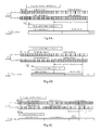
- the UE when the first mode is used for performing uplink power control, for Fig.4A , Fig.4B, Fig.4C, Fig.5 , Fig.6A, Fig.6B and Fig.6C , the UE can scale down the power of all the SC-FDMA symbols of the uplink signal in the uplink sub-frame i concurrently regardless of the number of SC-FDMA symbols, overlapping with the PRACH, in the uplink signal in the uplink sub-frame i.
- the UE can scale down the transmit power of only the overlapping SC-FDMA symbols regardless of the number of SC-FDMA symbols, overlapping with the PRACH, in the uplink signal in the uplink sub-frame i; or the UE can determine according to the slots including the overlapping SC-FDMA symbols, and for Fig.4A , Fig.4C , Fig.5 , Fig.6A and Fig.6B , the overlapping SC-FDMA symbols are included in two slots, and at this time the UE scales down the power of all the SC-FDMA symbols of the uplink signal concurrently; for Fig.4B , the overlapping SC-FDMA symbols are included in only the second slot, and at this time the UE scales down the power of the SC-FDMA symbols in only the second slot
- the third mode is used for performing uplink power control, for Fig.4A , Fig.4B, Fig.4C, Fig.5 , Fig.6A, Fig.6B and Fig.6C , if the sum of the target transmit power of the PUCCH and the PUSCH in the current uplink sub-frame does not exceed the maximum transmit power of the UE, then the second mode can be used for performing uplink power control; otherwise the power of all the SC-FDMA symbols of the uplink signal is scaled down concurrently.
- the number of SC-FDMA symbols is defined as 7 and the time length threshold T is defined as 0.5ms.
- the number of the overlapping SC-FDMA symbols exceeds N, or the length of the overlapping transmission time exceeds T, and at this time the UE scales down the power of all the SC-FDMA symbols of the uplink signal concurrently;
- the number of the overlapping SC-FDMA symbols does not exceed N, or the length of the overlapping transmission time does not exceed T, and at this time the UE scales down the power of only the overlapping SC-FDMA symbols; or for Fig.4B , the overlapping SC-FDMA symbols are included in only the second slot, and at this time the UE scales down the power of the SC-FDMA symbols in only the second slot; and for Fig.
- the mode 4-2 When the mode 4-2 is used for performing uplink power control, for Fig.4A , Fig.4B, Fig.4C, Fig.5 , Fig.6A, Fig.6B and Fig.6C , if the sum of the target transmit power of the PUCCH and the PUSCH in the uplink sub-frame i does not exceed the maximum transmit power of the UE, then the mode 4-1 can be used for performing uplink power control; otherwise, the power of all the SC-FDMA symbols of the uplink signal is scaled down concurrently.
- the respective synchronized uplink component carriers in the current uplink sub-frame and the uplink SCC on which the PRACH is transmitted belong to different TA groups. If the uplink signals transmitted on the respective synchronized uplink component carriers in the current uplink sub-frame include at least two uplink signals, then TA values of these uplink signals can be the same, that is, the uplink component carriers on which these uplink signals are transmitted can belong to the same TA group; or TA values of these uplink signals can be different, that is, the uplink component carriers on which these uplink signals are transmitted can belong to different TA groups.
- the uplink power control method according to the first embodiment of the invention can be not only applicable to the LTE system but also to an FDD (Frequency Division Duplexing) system and a TDD system.
- FDD Frequency Division Duplexing
- the UE determines target transmit power of uplink signals transmitted on respective synchronized uplink component carriers in a current uplink sub-frame, and judges whether a PRACH is transmitted on an uplink secondary component carrier in the current uplink sub-frame, and if so, then it indicates such a situation that the PRACH overlaps in transmission with the uplink signals occurs, and at this time the UE can determine target transmit power of the PRACH and further judge whether the sum of the target transmit power of the uplink signals and the target transmit power of the PRACH would exceed the maximum transmit power of the UE, and if so, then the UE maintains the target transmit power of the PRACH unchanged and scales down target transmit power of all or a part of SC-FDMA symbols of an uplink signal required to be power scaled among the uplink signals in the current uplink sub-frame until the sum of the transmit power of the uplink signals in the current uplink sub-frame does not exceed the maximum transmit power of the UE minus the
- the second embodiment of the invention proposes a UE, as illustrated in Fig.7 , which includes:
- a first transmit power determination unit 71 configured to determine target transmit power of uplink signals transmitted on respective synchronized uplink component carriers in a current uplink sub-frame;
- a channel judgment unit 72 configured to judge whether a PRACH is transmitted on an uplink secondary component carrier in the current uplink sub-frame
- a second transmit power determination unit 73 configured to determine target transmit power of the PRACH when the channel judgment unit 72 judges that the PRACH is transmitted on the uplink secondary component carrier in the current uplink sub-frame;
- a transmit power judgment unit 74 configured to judge whether a sum of the target transmit power of the uplink signals and the target transmit power of the PRACH would exceed the maximum transmit power of the UE;
- a power control unit 75 configured to maintain the target transmit power of the PRACH unchanged, and to scale down target transmit power of all or a part of SC-FDMA symbols of the uplink signal required to be power scaled among the uplink signals in the current uplink sub-frame until a sum of transmit power of the uplink signals in the current uplink sub-frame does not exceed the maximum transmit power of the UE minus the target transmit power of the PRACH when the transmit power judgment unit 74 judges that the sum of the target transmit power of the uplink signals and the target transmit power of the PRACH would exceed the maximum transmit power of the UE.
- the UE further includes a transmission unit configured to transmit with the target transmit power of the uplink signals and the target transmit power of the PRACH when the transmit power judgment unit 74 judges that the sum of the target transmit power of the uplink signals and the target transmit power of the PRACH does not exceed the maximum transmit power of the UE.
- the transmit power judgment unit 74 is further configured to judge whether a sum of the target transmit power of the uplink signals would exceed the maximum transmit power of the UE;
- the power control unit 75 is further configured to scale down target transmit power of all the SC-FDMA symbols of the uplink signal required to be power scaled among the uplink signals in the current uplink sub-frame until the sum of the transmit power of the uplink signals in the current uplink sub-frame does not exceed the maximum transmit power of the UE;
- the transmission unit is further configured to transmit with the target transmit power of the uplink signals.
- the UE further includes:
- An overlapping judgment unit configured, when the channel judgment unit 72 judges that no PRACH is transmitted on any uplink secondary component carrier in the current uplink sub-frame and a PRACH is transmitted on an uplink secondary component carrier in a previous adjacent uplink sub-frame of the current uplink sub-frame, to judge whether the uplink signals in the current uplink sub-frame overlap with a preamble sequence carried in the PRACH in the previous adjacent uplink sub-frame.
- the transmit power judgment unit 74 is further configured to judge whether a sum of the target transmit power of the uplink signals would exceed the maximum transmit power of the UE.
- the power control unit 75 is further configured to scale down target transmit power of all the SC-FDMA symbols of the uplink signal required to be power scaled among the uplink signals in the current uplink sub-frame until the sum of the transmit power of the uplink signals in the current uplink sub-frame does not exceed the maximum transmit power of the UE.
- the transmission unit is further configured to transmit with the target transmit power of the uplink signals.
- the second transmit power determination unit 73 is further configured to determine target transmit power of the PRACH in the previous adjacent uplink sub-frame;
- the transmit power judgment unit 74 is further configured to judge whether a sum of the target transmit power of the uplink signals in the current uplink sub-frame and the target transmit power of the PRACH in the previous adjacent uplink sub-frame would exceed the maximum transmit power of the UE.
- the power control unit 75 is further configured to maintain the target transmit power of the PRACH in the previous adjacent uplink sub-frame unchanged and to scale down target transmit power of all or a part of the SC-FDMA symbols of the uplink signal required to be power scaled among the uplink signals in the current uplink sub-frame until the sum of the transmit power of the uplink signals in the current uplink sub-frame does not exceed the maximum transmit power of the UE minus the target transmit power of the PRACH.
- the transmission unit is configured to transmit with the target transmit power of the uplink signals.
- the overlapping judgment unit is specifically configured:
- TA c represents a time advance of an uplink transmission timing of a carrier on which the uplink signal is transmitted, and c represents the index of the carrier on which the uplink signal is transmitted;
- ⁇ T D,c represents the difference in downlink reception timing between a carrier on which the PRACH is transmitted and the carrier on which the uplink signal is transmitted;
- T GT K ⁇ 1 - ( T CP + T SEQ ), where K represents the number of uplink sub-frames occupied by the preamble format corresponding to the preamble sequence, T CP represents the length of a CP in the preamble format, and T SEQ represents the length of a sequence in the preamble format.
- T TP represents the transient period defined at the initial transmission location of the uplink signal in the current uplink sub-frame.
- the power control unit 75 when the power control unit 75 is further configured to maintain the target transmit power of the PRACH in the previous adjacent uplink sub-frame unchanged and to scale down the target transmit power of a part of the SC-FDMA symbols of the uplink signal required to be power scaled among the uplink signals in the current uplink sub-frame, the power control unit 75 is specifically configured:
- the uplink signals include at least two uplink signals and the sum of the target transmit power of the respective uplink signals does not exceed the maximum transmit power of the UE, then for the uplink signal required to be power scaled among the uplink signals, to scale down target transmit power of SC-FDMA symbols, overlapping with the preamble sequence carried in the PRACH, in the uplink signal in the current uplink sub-frame, or to scale down target transmit power of all SC-FDMA symbols in a slot including SC-FDMA symbols, overlapping with the preamble sequence carried in the PRACH, in the uplink signal in the current uplink sub-frame; otherwise, for the uplink signal required to be power scaled among the uplink signals, to scale down target transmit power of all the SC-FDMA symbols of the uplink signal in the current uplink sub-frame.
- the power control unit 75 is specifically configured:
- the uplink signal For the uplink signal required to be power scaled among the uplink signals, to scale down target transmit power of SC-FDMA symbols, overlapping with a preamble sequence carried in the PRACH, in the uplink signal in the current uplink sub-frame, or to scale down target transmit power of all SC-FDMA symbols in a slot including SC-FDMA symbols, overlapping with the preamble sequence carried in the PRACH, in the uplink signal in the current uplink sub-frame, wherein the overlapping SC-FDMA symbols include SC-FDMA symbols, overlapping with the preamble sequence carried in the PRACH in the current uplink sub-frame or a previous adjacent uplink sub-frame, in the uplink signal.
- the power control unit 75 is specifically configured:
- the uplink signals include at least two uplink signals and the sum of the target transmit power of the respective uplink signals does not exceed the maximum transmit power of the UE, then for the uplink signal required to be power scaled among the uplink signals, to scale down target transmit power of SC-FDMA symbols, overlapping with a preamble sequence carried in the PRACH, in the uplink signal in the current uplink sub-frame, or to scale down target transmit power of all SC-FDMA symbols in a slot including SC-FDMA symbols, overlapping with the preamble sequence carried in the PRACH, in the uplink signal in the current uplink sub-frame, wherein the overlapping SC-FDMA symbols include SC-FDMA symbols, overlapping with the preamble sequence carried in the PRACH in the current uplink sub-frame or a previous adjacent uplink sub-frame, in the uplink signal; otherwise,
- the power control unit 75 is specifically configured:
- the uplink signal required to be power scaled among the uplink signals, to scale down the target transmit power of all or a part of the SC-FDMA symbols of the uplink signal according to the number of SC-FDMA symbols, overlapping with a preamble sequence carried in the PRACH, in the uplink signal in the current uplink sub-frame or a transmission time length of the uplink signal, overlapping with the preamble sequence carried in the PRACH, in the current uplink sub-frame, wherein the overlapping SC-FDMA symbols or the overlapping transmission time include or includes SC-FDMA symbols or transmission time, overlapping with the preamble sequence carried in the PRACH in the current uplink sub-frame or a previous adjacent uplink sub-frame, in the uplink signal.
- the power control unit 75 is specifically configured:
- the power control unit 75 is specifically configured:
- the uplink signals in the current uplink sub-frame include at least two uplink signals and the sum of the target transmit power of the respective uplink signals would exceed the maximum transmit power of the UE, to scale down the target transmit power of all the SC-FDMA symbols of the uplink signal required to be power scaled in the current uplink sub-frame; otherwise,
- the power control unit 75 is specifically configured:
- the uplink signals in the current uplink sub-frame includes an SRS, to determine an uplink signal with non-zero transmit power and with a lowest priority other than the SRS among the uplink signals in the current uplink sub-frame as the uplink signal required to be power scaled according to priorities of the uplink signals, to scale down the target transmit power of all or a part of the SC-FDMA symbols of the uplink signal required to be power scaled by a same scaling factor until a sum of target transmit power of other uplink signals than the SRS in the current uplink sub-frame does not exceed maximum transmit power currently available, and to scale down target transmit power of the SRS by a same scaling factor until a sum of transmit power of the SRS and transmit power of uplink signals overlapping with the SRS among the uplink signals in the current uplink sub-frame does not exceed the maximum transmit power currently available, wherein the maximum transmit power currently available is the maximum transmit power of the UE or the maximum transmit power of the UE minus the target transmit power of the PRACH.
- the priorities of the uplink signals from high to low are as follows: a PUCCH higher than a PUSCH with UCI higher than a PUSCH without UCI higher than an SRS.
- the uplink signals include a PUCCH and/or a PUSCH and/or an SRS.
- the embodiments of the invention can be embodied as a method, a system or a computer program product. Therefore the invention can be embodied in the form of an all-hardware embodiment, an all-software embodiment or an embodiment of software and hardware in combination. Furthermore, the invention can be embodied in the form of a computer program product embodied in one or more computer useable storage mediums (including but not limited to a disk memory, a CD-ROM, an optical memory, etc.) in which computer useable program codes are contained.
- a computer useable storage mediums including but not limited to a disk memory, a CD-ROM, an optical memory, etc.
- These computer program instructions can also be stored into a computer readable memory capable of directing the computer or the other programmable data processing device to operate in a specific manner so that the instructions stored in the computer readable memory create manufactures including instruction means which perform the functions specified in the flow(s) of the flow charts and/or the block(s) of the block diagrams.
- These computer program instructions can also be loaded onto the computer or the other programmable data processing device so that a series of operational steps are performed on the computer or the other programmable data processing device to create a computer implemented process so that the instructions executed on the computer or the other programmable device provide steps for performing the functions specified in the flow(s) of the flow charts and/or the block(s) of the block diagrams.
Landscapes
- Engineering & Computer Science (AREA)
- Computer Networks & Wireless Communication (AREA)
- Signal Processing (AREA)
- Mobile Radio Communication Systems (AREA)
Applications Claiming Priority (2)
| Application Number | Priority Date | Filing Date | Title |
|---|---|---|---|
| CN201210082455.3A CN103369650B (zh) | 2012-03-26 | 2012-03-26 | 一种上行功率控制方法及用户设备 |
| PCT/CN2013/072260 WO2013143382A1 (fr) | 2012-03-26 | 2013-03-06 | Procédé et équipement d'utilisateur pour une régulation de la puissance sur la liaison montante |
Publications (3)
| Publication Number | Publication Date |
|---|---|
| EP2833681A1 true EP2833681A1 (fr) | 2015-02-04 |
| EP2833681A4 EP2833681A4 (fr) | 2015-05-13 |
| EP2833681B1 EP2833681B1 (fr) | 2017-12-06 |
Family
ID=49258188
Family Applications (1)
| Application Number | Title | Priority Date | Filing Date |
|---|---|---|---|
| EP13767652.4A Active EP2833681B1 (fr) | 2012-03-26 | 2013-03-06 | Procédé et équipement d'utilisateur pour une régulation de la puissance sur la liaison montante |
Country Status (6)
| Country | Link |
|---|---|
| US (1) | US9918285B2 (fr) |
| EP (1) | EP2833681B1 (fr) |
| JP (1) | JP6062031B2 (fr) |
| KR (1) | KR20140140599A (fr) |
| CN (1) | CN103369650B (fr) |
| WO (1) | WO2013143382A1 (fr) |
Families Citing this family (55)
| Publication number | Priority date | Publication date | Assignee | Title |
|---|---|---|---|---|
| US8395985B2 (en) | 2011-07-25 | 2013-03-12 | Ofinno Technologies, Llc | Time alignment in multicarrier OFDM network |
| US9237537B2 (en) | 2012-01-25 | 2016-01-12 | Ofinno Technologies, Llc | Random access process in a multicarrier base station and wireless device |
| US8964683B2 (en) | 2012-04-20 | 2015-02-24 | Ofinno Technologies, Llc | Sounding signal in a multicarrier wireless device |
| US8526389B2 (en) | 2012-01-25 | 2013-09-03 | Ofinno Technologies, Llc | Power scaling in multicarrier wireless device |
| US8995405B2 (en) | 2012-01-25 | 2015-03-31 | Ofinno Technologies, Llc | Pathloss reference configuration in a wireless device and base station |
| US11943813B2 (en) | 2012-04-01 | 2024-03-26 | Comcast Cable Communications, Llc | Cell grouping for wireless communications |
| US9084270B2 (en) | 2012-04-01 | 2015-07-14 | Ofinno Technologies, Llc | Radio access for a wireless device and base station |
| WO2013151651A1 (fr) | 2012-04-01 | 2013-10-10 | Dinan Esmael Hejazi | Configuration de groupe de cellules dans un dispositif sans fil et station de base à groupes d'avance temporelle |
| US8958342B2 (en) | 2012-04-17 | 2015-02-17 | Ofinno Technologies, Llc | Uplink transmission power in a multicarrier wireless device |
| US8964593B2 (en) | 2012-04-16 | 2015-02-24 | Ofinno Technologies, Llc | Wireless device transmission power |
| US11582704B2 (en) | 2012-04-16 | 2023-02-14 | Comcast Cable Communications, Llc | Signal transmission power adjustment in a wireless device |
| EP2839705B1 (fr) | 2012-04-16 | 2017-09-06 | Comcast Cable Communications, LLC | Configuration avec groupes de cellules pour l'émission en liaison montante dans un dispositif sans fil multi-porteuses et station de base avec groupes d'avance de synchronisation |
| US11252679B2 (en) | 2012-04-16 | 2022-02-15 | Comcast Cable Communications, Llc | Signal transmission power adjustment in a wireless device |
| US11825419B2 (en) | 2012-04-16 | 2023-11-21 | Comcast Cable Communications, Llc | Cell timing in a wireless device and base station |
| US9179425B2 (en) | 2012-04-17 | 2015-11-03 | Ofinno Technologies, Llc | Transmit power control in multicarrier communications |
| US9107206B2 (en) | 2012-06-18 | 2015-08-11 | Ofinne Technologies, LLC | Carrier grouping in multicarrier wireless networks |
| US9113387B2 (en) | 2012-06-20 | 2015-08-18 | Ofinno Technologies, Llc | Handover signalling in wireless networks |
| US9084228B2 (en) | 2012-06-20 | 2015-07-14 | Ofinno Technologies, Llc | Automobile communication device |
| US8971298B2 (en) | 2012-06-18 | 2015-03-03 | Ofinno Technologies, Llc | Wireless device connection to an application server |
| US11882560B2 (en) | 2012-06-18 | 2024-01-23 | Comcast Cable Communications, Llc | Carrier grouping in multicarrier wireless networks |
| US9210619B2 (en) | 2012-06-20 | 2015-12-08 | Ofinno Technologies, Llc | Signalling mechanisms for wireless device handover |
| US11622372B2 (en) | 2012-06-18 | 2023-04-04 | Comcast Cable Communications, Llc | Communication device |
| US9179457B2 (en) | 2012-06-20 | 2015-11-03 | Ofinno Technologies, Llc | Carrier configuration in wireless networks |
| US10051665B2 (en) * | 2013-07-16 | 2018-08-14 | Lg Electronics Inc. | Method and apparatus for performing random access procedure in wireless communication system |
| US10542435B2 (en) | 2013-09-24 | 2020-01-21 | Qualcomm Incorporated | Carrier sense adaptive transmission (CSAT) in unlicensed spectrum |
| US9775048B2 (en) * | 2013-09-24 | 2017-09-26 | Qualcomm Incorporated | Performance of a user equipment (UE) in unlicensed spectrum |
| US10356623B2 (en) | 2013-09-24 | 2019-07-16 | Qualcomm Incorporated | Techniques for performing carrier sense adaptive transmission in unlicensed spectrum |
| CN104519561B (zh) * | 2013-09-26 | 2019-02-12 | 中兴通讯股份有限公司 | 上行功率削减处理方法、装置、终端及基站 |
| CN105191441B (zh) * | 2014-01-24 | 2019-08-16 | 华为技术有限公司 | 一种信道功率分配优先级的确定方法和设备 |
| CN104812046B (zh) * | 2014-01-28 | 2019-03-05 | 电信科学技术研究院 | 一种上行信道的功率控制方法及装置 |
| MX360822B (es) | 2014-04-18 | 2018-11-16 | Huawei Tech Co Ltd | Método de configuración de potencia, equipo de usuario y estación base. |
| JP6383999B2 (ja) * | 2014-05-08 | 2018-09-05 | ホアウェイ・テクノロジーズ・カンパニー・リミテッド | 電力割り当て方法、ユーザ機器及び基地局 |
| CN106416386B (zh) * | 2014-06-05 | 2020-07-07 | 夏普株式会社 | 终端装置以及方法 |
| EP3179644B1 (fr) | 2014-08-06 | 2019-11-20 | LG Electronics Inc. | Procédé d'émission de signal en liaison montante et équipement d'utilisateur, et procédé de réception de signal en liaison montante et station de base |
| US20160050667A1 (en) * | 2014-08-18 | 2016-02-18 | Samsung Electronics Co., Ltd. | Communication on licensed and unlicensed bands |
| CN107079502A (zh) | 2014-11-04 | 2017-08-18 | 瑞典爱立信有限公司 | 用于改进的随机接入传输的无线通信设备、网络节点及其中的方法 |
| CN114095996A (zh) | 2015-05-15 | 2022-02-25 | 北京三星通信技术研究有限公司 | 一种上行功率的分配方法和用户设备 |
| EP3360266A1 (fr) * | 2015-10-08 | 2018-08-15 | Telefonaktiebolaget LM Ericsson (publ.) | Combinaison de signaux radio de liaison montante |
| US10356800B2 (en) | 2016-05-09 | 2019-07-16 | Qualcomm Incorporated | Scalable numerology with symbol boundary alignment for uniform and non-uniform symbol duration in wireless communication |
| CN107371225B (zh) * | 2016-05-13 | 2020-01-07 | 电信科学技术研究院 | 一种上行共享信道的导频传输方法及相关设备 |
| JP6732050B2 (ja) * | 2016-05-13 | 2020-07-29 | 華為技術有限公司Huawei Technologies Co.,Ltd. | Ta取得方法及び装置 |
| US10616835B2 (en) * | 2016-06-02 | 2020-04-07 | Lg Electronics Inc. | Method for controlling uplink transmission power in wireless communication system, and apparatus therefor |
| CN107734688B (zh) * | 2016-08-12 | 2023-05-02 | 中兴通讯股份有限公司 | 一种信息发送方法及发送设备 |
| CN107734680B (zh) * | 2016-08-12 | 2023-05-09 | 中兴通讯股份有限公司 | 一种传输信息的方法及装置、接收信息的方法及装置 |
| EP3503633B1 (fr) * | 2016-11-03 | 2020-08-05 | Guangdong Oppo Mobile Telecommunications Corp., Ltd. | Procédé de communication, dispositif terminal, et dispositif de réseau |
| EP3577966A4 (fr) * | 2017-02-06 | 2020-12-09 | Telefonaktiebolaget LM Ericsson (publ) | Adaptation d'un paramètre temporel transitoire de marche/arrêt d'un ue pour différents modèles d'intervalle de temps d'émission |
| CN110999406A (zh) * | 2017-08-16 | 2020-04-10 | Oppo广东移动通信有限公司 | 信号传输的方法和终端设备 |
| WO2019142524A1 (fr) * | 2018-01-16 | 2019-07-25 | ソニー株式会社 | Dispositif de communication et procédé de communication |
| CN110113810B (zh) * | 2018-02-01 | 2021-02-26 | 华为技术有限公司 | 一种功率控制方法、相关装置及产品 |
| CN110351821B (zh) * | 2018-04-04 | 2021-06-01 | 华为技术有限公司 | 通信方法、通信装置以及计算机可读存储介质 |
| WO2020199002A1 (fr) * | 2019-03-29 | 2020-10-08 | Zte Corporation | Procédés, appareil et systèmes pour déterminer une puissance de transmission pour une transmission en liaison montante |
| WO2020199051A1 (fr) * | 2019-03-29 | 2020-10-08 | Oppo广东移动通信有限公司 | Procédé d'accès aléatoire, station de base, terminal et structure de canal |
| US11924819B2 (en) * | 2019-05-24 | 2024-03-05 | Qualcomm Incorporated | Power limits based on signal type for managing maximum permissible exposure |
| CN112311709B (zh) * | 2020-10-20 | 2024-09-27 | 陕西航天技术应用研究院有限公司 | 一种基于功率多址的信道解调方法、装置和系统 |
| US20230030066A1 (en) * | 2021-07-29 | 2023-02-02 | Qualcomm Incorporated | Intra-band carrier aggregation/dual connectivity |
Family Cites Families (12)
| Publication number | Priority date | Publication date | Assignee | Title |
|---|---|---|---|---|
| KR100735401B1 (ko) * | 2005-10-14 | 2007-07-04 | 삼성전자주식회사 | 물리 랜덤 액세스 채널의 전송 전력 제어방법 |
| CN101119146B (zh) * | 2007-09-03 | 2011-04-13 | 北京天碁科技有限公司 | 一种对通信终端发射功率进行校准的方法、系统和装置 |
| CN101394226A (zh) * | 2007-09-18 | 2009-03-25 | Nxp股份有限公司 | 蜂窝电话系统的具有多Zadoff-Chu序列的随机接入前同步码 |
| KR101674940B1 (ko) * | 2009-01-29 | 2016-11-10 | 엘지전자 주식회사 | 전송 전력을 제어하는 방법 및 이를 위한 장치 |
| WO2011040858A1 (fr) * | 2009-10-02 | 2011-04-07 | Telefonaktiebolaget Lm Ericsson (Publ) | Commande de la puissance d'une liaison montante dans un système de communication sans fil |
| MX2012002348A (es) * | 2009-10-05 | 2012-03-29 | Ericsson Telefon Ab L M | Metodos y arreglos en una red de telecomunicacion movil. |
| SMT201800459T1 (it) * | 2010-04-01 | 2018-11-09 | Sun Patent Trust | Controllo della potenza di trasmissione per canali fisici di accesso causale |
| KR101874276B1 (ko) * | 2010-04-01 | 2018-07-04 | 선 페이턴트 트러스트 | 물리적 랜덤 액세스 채널들에 대한 송신 전력 제어 |
| CN102238716A (zh) * | 2011-07-15 | 2011-11-09 | 电信科学技术研究院 | 一种调整发射功率的方法及装置 |
| CN102300305B (zh) * | 2011-09-23 | 2013-09-04 | 电信科学技术研究院 | 一种上行功率控制的方法及装置 |
| CN102348269B (zh) * | 2011-09-27 | 2015-01-28 | 电信科学技术研究院 | 一种上行功率控制的方法和设备 |
| CN102378341A (zh) * | 2011-11-17 | 2012-03-14 | 电信科学技术研究院 | 一种上行功率控制方法及装置 |
-
2012
- 2012-03-26 CN CN201210082455.3A patent/CN103369650B/zh active Active
-
2013
- 2013-03-06 WO PCT/CN2013/072260 patent/WO2013143382A1/fr not_active Ceased
- 2013-03-06 KR KR20147029728A patent/KR20140140599A/ko not_active Ceased
- 2013-03-06 JP JP2015502068A patent/JP6062031B2/ja active Active
- 2013-03-06 EP EP13767652.4A patent/EP2833681B1/fr active Active
- 2013-03-06 US US14/388,794 patent/US9918285B2/en active Active
Also Published As
| Publication number | Publication date |
|---|---|
| CN103369650A (zh) | 2013-10-23 |
| JP2015515197A (ja) | 2015-05-21 |
| KR20140140599A (ko) | 2014-12-09 |
| EP2833681A4 (fr) | 2015-05-13 |
| JP6062031B2 (ja) | 2017-01-18 |
| US9918285B2 (en) | 2018-03-13 |
| EP2833681B1 (fr) | 2017-12-06 |
| WO2013143382A1 (fr) | 2013-10-03 |
| US20150063245A1 (en) | 2015-03-05 |
| CN103369650B (zh) | 2017-02-08 |
Similar Documents
| Publication | Publication Date | Title |
|---|---|---|
| US9918285B2 (en) | Method and user equipment of uplink power control | |
| US12356336B2 (en) | Signal transmission power adjustment in a wireless device | |
| EP3668251B1 (fr) | Procédé de réalisation de processus d'accès aléatoire et dispositif associé | |
| JP7157762B2 (ja) | ランダム接続過程を行う方法及びそのための装置 | |
| EP2693801B1 (fr) | Procédé et dispositif de transmission sur la liaison montante pour système à agrégation de porteuses multiples | |
| EP2475205B1 (fr) | Procédé d'accès terminal, système et dispositifs associés | |
| EP3169119B1 (fr) | Procédé et appareil de réglage de la puissance d'émission dans le sens montant | |
| US10575259B2 (en) | Signal power management in a multicarrier wireless device | |
| EP2797246B1 (fr) | Procédé et appareil d'acquisition de synchronisation de liaison montante dans un système de communication sans fil | |
| EP2739094B1 (fr) | Procédé et terminal de régulation de puissance | |
| CN102231917B (zh) | 一种随机接入的方法及装置 | |
| CN102281626B (zh) | 一种上行定时提前量的确定方法及装置 | |
| CN111614453B (zh) | 配置上行传输定时的方法和设备 | |
| EP2840844A2 (fr) | Alignement de synchronisation de liaison montante | |
| US20200245364A1 (en) | Method for transmitting and receiving uplink data between terminal and base station in wireless communication system and device supporting same | |
| EP2785119A1 (fr) | Procédé et équipement d'utilisateur pour réguler la puissance d'émission en liaison montante | |
| EP3337079A1 (fr) | Configuration avec groupes de cellules pour l'émission en liaison montante dans un dispositif sans fil multi-porteuses et station de base avec groupes d'avance de synchronisation | |
| EP3668250A1 (fr) | Procédé de réalisation d'un processus d'accès aléatoire et appareil associé | |
| EP3503660B1 (fr) | Procédé de transmission de signal montant par de multiples porteuses composantes non soumises à licence dans un système de communication sans fil prenant en charge une bande de fréquence non soumise à licence, et dispositif le prenant en charge | |
| CN102325382A (zh) | 随机接入方法和设备 | |
| JP2015165718A (ja) | 無線通信システムにおいてランダムアクセス過程を行う方法及び装置 | |
| EP2838302B1 (fr) | Station mobile | |
| CN105846975A (zh) | 一种配置上下行子帧的方法及设备 | |
| US9801209B2 (en) | Method for transmitting random access preamble, and wireless device |
Legal Events
| Date | Code | Title | Description |
|---|---|---|---|
| PUAI | Public reference made under article 153(3) epc to a published international application that has entered the european phase |
Free format text: ORIGINAL CODE: 0009012 |
|
| 17P | Request for examination filed |
Effective date: 20141022 |
|
| AK | Designated contracting states |
Kind code of ref document: A1 Designated state(s): AL AT BE BG CH CY CZ DE DK EE ES FI FR GB GR HR HU IE IS IT LI LT LU LV MC MK MT NL NO PL PT RO RS SE SI SK SM TR |
|
| AX | Request for extension of the european patent |
Extension state: BA ME |
|
| RA4 | Supplementary search report drawn up and despatched (corrected) |
Effective date: 20150415 |
|
| RIC1 | Information provided on ipc code assigned before grant |
Ipc: H04W 52/14 20090101AFI20150409BHEP Ipc: H04W 52/36 20090101ALI20150409BHEP Ipc: H04W 52/50 20090101ALI20150409BHEP Ipc: H04W 52/34 20090101ALI20150409BHEP Ipc: H04W 52/32 20090101ALI20150409BHEP |
|
| DAX | Request for extension of the european patent (deleted) | ||
| 17Q | First examination report despatched |
Effective date: 20160218 |
|
| STAA | Information on the status of an ep patent application or granted ep patent |
Free format text: STATUS: EXAMINATION IS IN PROGRESS |
|
| GRAP | Despatch of communication of intention to grant a patent |
Free format text: ORIGINAL CODE: EPIDOSNIGR1 |
|
| STAA | Information on the status of an ep patent application or granted ep patent |
Free format text: STATUS: GRANT OF PATENT IS INTENDED |
|
| INTG | Intention to grant announced |
Effective date: 20170628 |
|
| GRAS | Grant fee paid |
Free format text: ORIGINAL CODE: EPIDOSNIGR3 |
|
| GRAA | (expected) grant |
Free format text: ORIGINAL CODE: 0009210 |
|
| STAA | Information on the status of an ep patent application or granted ep patent |
Free format text: STATUS: THE PATENT HAS BEEN GRANTED |
|
| AK | Designated contracting states |
Kind code of ref document: B1 Designated state(s): AL AT BE BG CH CY CZ DE DK EE ES FI FR GB GR HR HU IE IS IT LI LT LU LV MC MK MT NL NO PL PT RO RS SE SI SK SM TR |
|
| REG | Reference to a national code |
Ref country code: GB Ref legal event code: FG4D |
|
| REG | Reference to a national code |
Ref country code: AT Ref legal event code: REF Ref document number: 953415 Country of ref document: AT Kind code of ref document: T Effective date: 20171215 Ref country code: CH Ref legal event code: EP |
|
| REG | Reference to a national code |
Ref country code: IE Ref legal event code: FG4D |
|
| REG | Reference to a national code |
Ref country code: DE Ref legal event code: R096 Ref document number: 602013030454 Country of ref document: DE |
|
| REG | Reference to a national code |
Ref country code: FR Ref legal event code: PLFP Year of fee payment: 6 |
|
| REG | Reference to a national code |
Ref country code: NL Ref legal event code: MP Effective date: 20171206 |
|
| REG | Reference to a national code |
Ref country code: LT Ref legal event code: MG4D |
|
| PG25 | Lapsed in a contracting state [announced via postgrant information from national office to epo] |
Ref country code: LT Free format text: LAPSE BECAUSE OF FAILURE TO SUBMIT A TRANSLATION OF THE DESCRIPTION OR TO PAY THE FEE WITHIN THE PRESCRIBED TIME-LIMIT Effective date: 20171206 Ref country code: FI Free format text: LAPSE BECAUSE OF FAILURE TO SUBMIT A TRANSLATION OF THE DESCRIPTION OR TO PAY THE FEE WITHIN THE PRESCRIBED TIME-LIMIT Effective date: 20171206 Ref country code: SE Free format text: LAPSE BECAUSE OF FAILURE TO SUBMIT A TRANSLATION OF THE DESCRIPTION OR TO PAY THE FEE WITHIN THE PRESCRIBED TIME-LIMIT Effective date: 20171206 Ref country code: NO Free format text: LAPSE BECAUSE OF FAILURE TO SUBMIT A TRANSLATION OF THE DESCRIPTION OR TO PAY THE FEE WITHIN THE PRESCRIBED TIME-LIMIT Effective date: 20180306 Ref country code: ES Free format text: LAPSE BECAUSE OF FAILURE TO SUBMIT A TRANSLATION OF THE DESCRIPTION OR TO PAY THE FEE WITHIN THE PRESCRIBED TIME-LIMIT Effective date: 20171206 |
|
| REG | Reference to a national code |
Ref country code: AT Ref legal event code: MK05 Ref document number: 953415 Country of ref document: AT Kind code of ref document: T Effective date: 20171206 |
|
| PG25 | Lapsed in a contracting state [announced via postgrant information from national office to epo] |
Ref country code: LV Free format text: LAPSE BECAUSE OF FAILURE TO SUBMIT A TRANSLATION OF THE DESCRIPTION OR TO PAY THE FEE WITHIN THE PRESCRIBED TIME-LIMIT Effective date: 20171206 Ref country code: BG Free format text: LAPSE BECAUSE OF FAILURE TO SUBMIT A TRANSLATION OF THE DESCRIPTION OR TO PAY THE FEE WITHIN THE PRESCRIBED TIME-LIMIT Effective date: 20180306 Ref country code: HR Free format text: LAPSE BECAUSE OF FAILURE TO SUBMIT A TRANSLATION OF THE DESCRIPTION OR TO PAY THE FEE WITHIN THE PRESCRIBED TIME-LIMIT Effective date: 20171206 Ref country code: RS Free format text: LAPSE BECAUSE OF FAILURE TO SUBMIT A TRANSLATION OF THE DESCRIPTION OR TO PAY THE FEE WITHIN THE PRESCRIBED TIME-LIMIT Effective date: 20171206 Ref country code: GR Free format text: LAPSE BECAUSE OF FAILURE TO SUBMIT A TRANSLATION OF THE DESCRIPTION OR TO PAY THE FEE WITHIN THE PRESCRIBED TIME-LIMIT Effective date: 20180307 |
|
| PG25 | Lapsed in a contracting state [announced via postgrant information from national office to epo] |
Ref country code: NL Free format text: LAPSE BECAUSE OF FAILURE TO SUBMIT A TRANSLATION OF THE DESCRIPTION OR TO PAY THE FEE WITHIN THE PRESCRIBED TIME-LIMIT Effective date: 20171206 |
|
| PG25 | Lapsed in a contracting state [announced via postgrant information from national office to epo] |
Ref country code: CZ Free format text: LAPSE BECAUSE OF FAILURE TO SUBMIT A TRANSLATION OF THE DESCRIPTION OR TO PAY THE FEE WITHIN THE PRESCRIBED TIME-LIMIT Effective date: 20171206 Ref country code: SK Free format text: LAPSE BECAUSE OF FAILURE TO SUBMIT A TRANSLATION OF THE DESCRIPTION OR TO PAY THE FEE WITHIN THE PRESCRIBED TIME-LIMIT Effective date: 20171206 Ref country code: EE Free format text: LAPSE BECAUSE OF FAILURE TO SUBMIT A TRANSLATION OF THE DESCRIPTION OR TO PAY THE FEE WITHIN THE PRESCRIBED TIME-LIMIT Effective date: 20171206 |
|
| PG25 | Lapsed in a contracting state [announced via postgrant information from national office to epo] |
Ref country code: PL Free format text: LAPSE BECAUSE OF FAILURE TO SUBMIT A TRANSLATION OF THE DESCRIPTION OR TO PAY THE FEE WITHIN THE PRESCRIBED TIME-LIMIT Effective date: 20171206 Ref country code: RO Free format text: LAPSE BECAUSE OF FAILURE TO SUBMIT A TRANSLATION OF THE DESCRIPTION OR TO PAY THE FEE WITHIN THE PRESCRIBED TIME-LIMIT Effective date: 20171206 Ref country code: AT Free format text: LAPSE BECAUSE OF FAILURE TO SUBMIT A TRANSLATION OF THE DESCRIPTION OR TO PAY THE FEE WITHIN THE PRESCRIBED TIME-LIMIT Effective date: 20171206 Ref country code: IT Free format text: LAPSE BECAUSE OF FAILURE TO SUBMIT A TRANSLATION OF THE DESCRIPTION OR TO PAY THE FEE WITHIN THE PRESCRIBED TIME-LIMIT Effective date: 20171206 Ref country code: SM Free format text: LAPSE BECAUSE OF FAILURE TO SUBMIT A TRANSLATION OF THE DESCRIPTION OR TO PAY THE FEE WITHIN THE PRESCRIBED TIME-LIMIT Effective date: 20171206 |
|
| REG | Reference to a national code |
Ref country code: DE Ref legal event code: R097 Ref document number: 602013030454 Country of ref document: DE |
|
| PLBE | No opposition filed within time limit |
Free format text: ORIGINAL CODE: 0009261 |
|
| STAA | Information on the status of an ep patent application or granted ep patent |
Free format text: STATUS: NO OPPOSITION FILED WITHIN TIME LIMIT |
|
| REG | Reference to a national code |
Ref country code: CH Ref legal event code: PL |
|
| 26N | No opposition filed |
Effective date: 20180907 |
|
| PG25 | Lapsed in a contracting state [announced via postgrant information from national office to epo] |
Ref country code: SI Free format text: LAPSE BECAUSE OF FAILURE TO SUBMIT A TRANSLATION OF THE DESCRIPTION OR TO PAY THE FEE WITHIN THE PRESCRIBED TIME-LIMIT Effective date: 20171206 Ref country code: MC Free format text: LAPSE BECAUSE OF FAILURE TO SUBMIT A TRANSLATION OF THE DESCRIPTION OR TO PAY THE FEE WITHIN THE PRESCRIBED TIME-LIMIT Effective date: 20171206 Ref country code: DK Free format text: LAPSE BECAUSE OF FAILURE TO SUBMIT A TRANSLATION OF THE DESCRIPTION OR TO PAY THE FEE WITHIN THE PRESCRIBED TIME-LIMIT Effective date: 20171206 |
|
| REG | Reference to a national code |
Ref country code: BE Ref legal event code: MM Effective date: 20180331 |
|
| REG | Reference to a national code |
Ref country code: IE Ref legal event code: MM4A |
|
| PG25 | Lapsed in a contracting state [announced via postgrant information from national office to epo] |
Ref country code: LU Free format text: LAPSE BECAUSE OF NON-PAYMENT OF DUE FEES Effective date: 20180306 |
|
| PG25 | Lapsed in a contracting state [announced via postgrant information from national office to epo] |
Ref country code: IE Free format text: LAPSE BECAUSE OF NON-PAYMENT OF DUE FEES Effective date: 20180306 |
|
| PG25 | Lapsed in a contracting state [announced via postgrant information from national office to epo] |
Ref country code: LI Free format text: LAPSE BECAUSE OF NON-PAYMENT OF DUE FEES Effective date: 20180331 Ref country code: CH Free format text: LAPSE BECAUSE OF NON-PAYMENT OF DUE FEES Effective date: 20180331 Ref country code: BE Free format text: LAPSE BECAUSE OF NON-PAYMENT OF DUE FEES Effective date: 20180331 |
|
| PG25 | Lapsed in a contracting state [announced via postgrant information from national office to epo] |
Ref country code: MT Free format text: LAPSE BECAUSE OF NON-PAYMENT OF DUE FEES Effective date: 20180306 |
|
| PG25 | Lapsed in a contracting state [announced via postgrant information from national office to epo] |
Ref country code: TR Free format text: LAPSE BECAUSE OF FAILURE TO SUBMIT A TRANSLATION OF THE DESCRIPTION OR TO PAY THE FEE WITHIN THE PRESCRIBED TIME-LIMIT Effective date: 20171206 |
|
| PG25 | Lapsed in a contracting state [announced via postgrant information from national office to epo] |
Ref country code: PT Free format text: LAPSE BECAUSE OF FAILURE TO SUBMIT A TRANSLATION OF THE DESCRIPTION OR TO PAY THE FEE WITHIN THE PRESCRIBED TIME-LIMIT Effective date: 20171206 |
|
| PG25 | Lapsed in a contracting state [announced via postgrant information from national office to epo] |
Ref country code: MK Free format text: LAPSE BECAUSE OF NON-PAYMENT OF DUE FEES Effective date: 20171206 Ref country code: CY Free format text: LAPSE BECAUSE OF FAILURE TO SUBMIT A TRANSLATION OF THE DESCRIPTION OR TO PAY THE FEE WITHIN THE PRESCRIBED TIME-LIMIT Effective date: 20171206 Ref country code: HU Free format text: LAPSE BECAUSE OF FAILURE TO SUBMIT A TRANSLATION OF THE DESCRIPTION OR TO PAY THE FEE WITHIN THE PRESCRIBED TIME-LIMIT; INVALID AB INITIO Effective date: 20130306 |
|
| PG25 | Lapsed in a contracting state [announced via postgrant information from national office to epo] |
Ref country code: IS Free format text: LAPSE BECAUSE OF FAILURE TO SUBMIT A TRANSLATION OF THE DESCRIPTION OR TO PAY THE FEE WITHIN THE PRESCRIBED TIME-LIMIT Effective date: 20180406 Ref country code: AL Free format text: LAPSE BECAUSE OF FAILURE TO SUBMIT A TRANSLATION OF THE DESCRIPTION OR TO PAY THE FEE WITHIN THE PRESCRIBED TIME-LIMIT Effective date: 20171206 |
|
| REG | Reference to a national code |
Ref country code: DE Ref legal event code: R081 Ref document number: 602013030454 Country of ref document: DE Owner name: DATANG MOBILE COMMUNICATIONS EQUIPMENT CO., LT, CN Free format text: FORMER OWNER: CHINA ACADEMY OF TELECOMMUNICATIONS TECHNOLOGY, BEIJING, CN |
|
| REG | Reference to a national code |
Ref country code: GB Ref legal event code: 732E Free format text: REGISTERED BETWEEN 20211007 AND 20211013 |
|
| P01 | Opt-out of the competence of the unified patent court (upc) registered |
Effective date: 20230512 |
|
| PGFP | Annual fee paid to national office [announced via postgrant information from national office to epo] |
Ref country code: GB Payment date: 20260324 Year of fee payment: 14 |
|
| PGFP | Annual fee paid to national office [announced via postgrant information from national office to epo] |
Ref country code: DE Payment date: 20260319 Year of fee payment: 14 |
|
| PGFP | Annual fee paid to national office [announced via postgrant information from national office to epo] |
Ref country code: FR Payment date: 20260320 Year of fee payment: 14 |