EP2833792B1 - Procédé pour l'élastographie par ondes de cisaillement par transmission d'ultrasons avec des sous-groupes d'éléments transducteurs d'ultrasons - Google Patents
Procédé pour l'élastographie par ondes de cisaillement par transmission d'ultrasons avec des sous-groupes d'éléments transducteurs d'ultrasons Download PDFInfo
- Publication number
- EP2833792B1 EP2833792B1 EP13844234.8A EP13844234A EP2833792B1 EP 2833792 B1 EP2833792 B1 EP 2833792B1 EP 13844234 A EP13844234 A EP 13844234A EP 2833792 B1 EP2833792 B1 EP 2833792B1
- Authority
- EP
- European Patent Office
- Prior art keywords
- different
- ultrasound
- beams
- transducer elements
- shear wave
- Prior art date
- Legal status (The legal status is an assumption and is not a legal conclusion. Google has not performed a legal analysis and makes no representation as to the accuracy of the status listed.)
- Active
Links
Images


Classifications
-
- A—HUMAN NECESSITIES
- A61—MEDICAL OR VETERINARY SCIENCE; HYGIENE
- A61B—DIAGNOSIS; SURGERY; IDENTIFICATION
- A61B8/00—Diagnosis using ultrasonic, sonic or infrasonic waves
- A61B8/44—Constructional features of the ultrasonic, sonic or infrasonic diagnostic device
- A61B8/4483—Constructional features of the ultrasonic, sonic or infrasonic diagnostic device characterised by features of the ultrasound transducer
- A61B8/4488—Constructional features of the ultrasonic, sonic or infrasonic diagnostic device characterised by features of the ultrasound transducer the transducer being a phased array
-
- A—HUMAN NECESSITIES
- A61—MEDICAL OR VETERINARY SCIENCE; HYGIENE
- A61B—DIAGNOSIS; SURGERY; IDENTIFICATION
- A61B8/00—Diagnosis using ultrasonic, sonic or infrasonic waves
- A61B8/48—Diagnostic techniques
- A61B8/485—Diagnostic techniques involving measuring strain or elastic properties
-
- A—HUMAN NECESSITIES
- A61—MEDICAL OR VETERINARY SCIENCE; HYGIENE
- A61B—DIAGNOSIS; SURGERY; IDENTIFICATION
- A61B8/00—Diagnosis using ultrasonic, sonic or infrasonic waves
- A61B8/08—Clinical applications
-
- A—HUMAN NECESSITIES
- A61—MEDICAL OR VETERINARY SCIENCE; HYGIENE
- A61B—DIAGNOSIS; SURGERY; IDENTIFICATION
- A61B8/00—Diagnosis using ultrasonic, sonic or infrasonic waves
- A61B8/44—Constructional features of the ultrasonic, sonic or infrasonic diagnostic device
- A61B8/4483—Constructional features of the ultrasonic, sonic or infrasonic diagnostic device characterised by features of the ultrasound transducer
- A61B8/4494—Constructional features of the ultrasonic, sonic or infrasonic diagnostic device characterised by features of the ultrasound transducer characterised by the arrangement of the transducer elements
-
- A—HUMAN NECESSITIES
- A61—MEDICAL OR VETERINARY SCIENCE; HYGIENE
- A61B—DIAGNOSIS; SURGERY; IDENTIFICATION
- A61B8/00—Diagnosis using ultrasonic, sonic or infrasonic waves
- A61B8/52—Devices using data or image processing specially adapted for diagnosis using ultrasonic, sonic or infrasonic waves
- A61B8/5215—Devices using data or image processing specially adapted for diagnosis using ultrasonic, sonic or infrasonic waves involving processing of medical diagnostic data
- A61B8/5223—Devices using data or image processing specially adapted for diagnosis using ultrasonic, sonic or infrasonic waves involving processing of medical diagnostic data for extracting a diagnostic or physiological parameter from medical diagnostic data
-
- G—PHYSICS
- G01—MEASURING; TESTING
- G01N—INVESTIGATING OR ANALYSING MATERIALS BY DETERMINING THEIR CHEMICAL OR PHYSICAL PROPERTIES
- G01N29/00—Investigating or analysing materials by the use of ultrasonic, sonic or infrasonic waves; Visualisation of the interior of objects by transmitting ultrasonic or sonic waves through the object
- G01N29/04—Analysing solids
- G01N29/07—Analysing solids by measuring propagation velocity or propagation time of acoustic waves
-
- G—PHYSICS
- G01—MEASURING; TESTING
- G01N—INVESTIGATING OR ANALYSING MATERIALS BY DETERMINING THEIR CHEMICAL OR PHYSICAL PROPERTIES
- G01N29/00—Investigating or analysing materials by the use of ultrasonic, sonic or infrasonic waves; Visualisation of the interior of objects by transmitting ultrasonic or sonic waves through the object
- G01N29/22—Details, e.g. general constructional or apparatus details
- G01N29/26—Arrangements for orientation or scanning by relative movement of the head and the sensor
- G01N29/262—Arrangements for orientation or scanning by relative movement of the head and the sensor by electronic orientation or focusing, e.g. with phased arrays
-
- G—PHYSICS
- G01—MEASURING; TESTING
- G01S—RADIO DIRECTION-FINDING; RADIO NAVIGATION; DETERMINING DISTANCE OR VELOCITY BY USE OF RADIO WAVES; LOCATING OR PRESENCE-DETECTING BY USE OF THE REFLECTION OR RERADIATION OF RADIO WAVES; ANALOGOUS ARRANGEMENTS USING OTHER WAVES
- G01S15/00—Systems using the reflection or reradiation of acoustic waves, e.g. sonar systems
- G01S15/88—Sonar systems specially adapted for specific applications
- G01S15/89—Sonar systems specially adapted for specific applications for mapping or imaging
- G01S15/8906—Short-range imaging systems; Acoustic microscope systems using pulse-echo techniques
- G01S15/8909—Short-range imaging systems; Acoustic microscope systems using pulse-echo techniques using a static transducer configuration
- G01S15/8915—Short-range imaging systems; Acoustic microscope systems using pulse-echo techniques using a static transducer configuration using a transducer array
- G01S15/8927—Short-range imaging systems; Acoustic microscope systems using pulse-echo techniques using a static transducer configuration using a transducer array using simultaneously or sequentially two or more subarrays or subapertures
-
- G—PHYSICS
- G01—MEASURING; TESTING
- G01S—RADIO DIRECTION-FINDING; RADIO NAVIGATION; DETERMINING DISTANCE OR VELOCITY BY USE OF RADIO WAVES; LOCATING OR PRESENCE-DETECTING BY USE OF THE REFLECTION OR RERADIATION OF RADIO WAVES; ANALOGOUS ARRANGEMENTS USING OTHER WAVES
- G01S7/00—Details of systems according to groups G01S13/00, G01S15/00, G01S17/00
- G01S7/52—Details of systems according to groups G01S13/00, G01S15/00, G01S17/00 of systems according to group G01S15/00
- G01S7/52017—Details of systems according to groups G01S13/00, G01S15/00, G01S17/00 of systems according to group G01S15/00 particularly adapted to short-range imaging
- G01S7/52019—Details of transmitters
- G01S7/5202—Details of transmitters for pulse systems
- G01S7/52022—Details of transmitters for pulse systems using a sequence of pulses, at least one pulse manipulating the transmissivity or reflexivity of the medium
-
- G—PHYSICS
- G01—MEASURING; TESTING
- G01S—RADIO DIRECTION-FINDING; RADIO NAVIGATION; DETERMINING DISTANCE OR VELOCITY BY USE OF RADIO WAVES; LOCATING OR PRESENCE-DETECTING BY USE OF THE REFLECTION OR RERADIATION OF RADIO WAVES; ANALOGOUS ARRANGEMENTS USING OTHER WAVES
- G01S7/00—Details of systems according to groups G01S13/00, G01S15/00, G01S17/00
- G01S7/52—Details of systems according to groups G01S13/00, G01S15/00, G01S17/00 of systems according to group G01S15/00
- G01S7/52017—Details of systems according to groups G01S13/00, G01S15/00, G01S17/00 of systems according to group G01S15/00 particularly adapted to short-range imaging
- G01S7/52023—Details of receivers
- G01S7/52036—Details of receivers using analysis of echo signal for target characterisation
- G01S7/52042—Details of receivers using analysis of echo signal for target characterisation determining elastic properties of the propagation medium or of the reflective target
-
- G—PHYSICS
- G01—MEASURING; TESTING
- G01S—RADIO DIRECTION-FINDING; RADIO NAVIGATION; DETERMINING DISTANCE OR VELOCITY BY USE OF RADIO WAVES; LOCATING OR PRESENCE-DETECTING BY USE OF THE REFLECTION OR RERADIATION OF RADIO WAVES; ANALOGOUS ARRANGEMENTS USING OTHER WAVES
- G01S7/00—Details of systems according to groups G01S13/00, G01S15/00, G01S17/00
- G01S7/52—Details of systems according to groups G01S13/00, G01S15/00, G01S17/00 of systems according to group G01S15/00
- G01S7/52017—Details of systems according to groups G01S13/00, G01S15/00, G01S17/00 of systems according to group G01S15/00 particularly adapted to short-range imaging
- G01S7/52085—Details related to the ultrasound signal acquisition, e.g. scan sequences
- G01S7/5209—Details related to the ultrasound signal acquisition, e.g. scan sequences using multibeam transmission
-
- G—PHYSICS
- G01—MEASURING; TESTING
- G01N—INVESTIGATING OR ANALYSING MATERIALS BY DETERMINING THEIR CHEMICAL OR PHYSICAL PROPERTIES
- G01N2291/00—Indexing codes associated with group G01N29/00
- G01N2291/01—Indexing codes associated with the measuring variable
- G01N2291/011—Velocity or travel time
-
- G—PHYSICS
- G01—MEASURING; TESTING
- G01N—INVESTIGATING OR ANALYSING MATERIALS BY DETERMINING THEIR CHEMICAL OR PHYSICAL PROPERTIES
- G01N2291/00—Indexing codes associated with group G01N29/00
- G01N2291/02—Indexing codes associated with the analysed material
- G01N2291/024—Mixtures
- G01N2291/02475—Tissue characterisation
-
- G—PHYSICS
- G01—MEASURING; TESTING
- G01N—INVESTIGATING OR ANALYSING MATERIALS BY DETERMINING THEIR CHEMICAL OR PHYSICAL PROPERTIES
- G01N2291/00—Indexing codes associated with group G01N29/00
- G01N2291/02—Indexing codes associated with the analysed material
- G01N2291/028—Material parameters
- G01N2291/02827—Elastic parameters, strength or force
-
- G—PHYSICS
- G01—MEASURING; TESTING
- G01N—INVESTIGATING OR ANALYSING MATERIALS BY DETERMINING THEIR CHEMICAL OR PHYSICAL PROPERTIES
- G01N2291/00—Indexing codes associated with group G01N29/00
- G01N2291/04—Wave modes and trajectories
- G01N2291/042—Wave modes
- G01N2291/0422—Shear waves, transverse waves, horizontally polarised waves
Definitions
- the field of the invention is systems and methods for ultrasound imaging. More particularly, the invention relates to a method for shear wave elastography using ultrasound.
- Shear waves can be used to evaluate the viscoelastic properties of tissue, which are sensitive biomarkers of tissue pathology.
- an ultrasound imaging system with a frame rate of several kilohertz is required to capture the fast moving shear waves. This is not feasible with conventional ultrasound imaging systems, which typically have a frame rate of less than 100 Hz and where two-dimensional images are formed line by line.
- Described here are systems and methods for performing shear wave elastography using push and/or detection ultrasound beams that are generated by subsets of the available number of transducer elements in an ultrasound transducer. These techniques provide several advantages over currently available approaches to shear wave elastography, including the ability to use a standard, low frame rate ultrasound imaging system and the ability to measure shear wave speed throughout the entire field-of-view rather than only those regions where the push beams are not generated.
- High-end, conventional ultrasound imaging systems can image several lines from a single transmission using parallel beam forming.
- the detection PRF at each spatial location can be less than 1 kHz. That is to say, using 1 kHz as an example, it is sufficient to perform shear wave elastography detection at the same spatial location only once every 1000 microseconds. Therefore, shear wave elastography can be performed using parallel beam forming detection at multiple locations sequentially while maintaining a PRF of 1 kHz at each location.
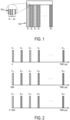
- the sequence of ultrasound beams includes N sets, S 1 ,...,S N 102 each of M beams, B 1 ,...,B M 104 formed in parallel. This sequence is then repeated at the pulse repetition frequency for a number, P , of desired repetitions.
- each set, S n , of ultrasound beams may include a plurality of beams, B m , that are formed in parallel.
- each set of ultrasound beams may include four beams formed in parallel and twenty beam sets may be used for a total sampling of eighty different locations during each pulse sequence.
- shear wave motion can be detected within a two-dimensional region covered by the M ⁇ N spatial locations with an effective PRF of 1 kHz at each spatial location.
- two-dimensional shear wave elastography can be performed within an area that is 30 mm deep and 24 mm wide using this technique.
- each set of ultrasound beams may include only a single ultrasound beam. As a result, the region-of-interest in which mechanical properties can be measured will be smaller than with parallel beam forming.
- FIG. 2 An example pulse sequence timing for P repetitions of the pulse sequence illustrated in FIG. 1 is illustrated in FIG. 2 .
- transmission of beam set S 1,1 is used to track shear wave motion at beam locations defined by the beams, B m , that form beam set S 1,1 .
- beam set S 1,1 is composed of four beams, shear wave motion at four locations will be tracked.
- beam set S 2,1 is generated to detect shear wave motion occurring at beam locations defined by the beams, B m , that form beam set S 2,1 .
- the preset time may be 50 microseconds.
- the first beam set is again transmitted.
- the size of the two-dimensional shear wave elastography region is determined by the parallel beam forming capability of the ultrasound system and the required PRF at each spatial location. For example, six-beam parallel detection can allow a 36 mm image width if everything else does not change. It is contemplated that the required PRF may be higher in stiffer tissues. In this instance, the two-dimensional shear wave elastography region will be reduced in size in order to sustain the higher PRF. Therefore, implementations on traditional imagers may end up with a region-of-interest whose size changes with different applications. This result is similar to current two-dimensional color imaging methods in ultrasound scanners.
- the PRF at each location is 1 kHz
- different locations are sampled at different time grids.
- One example method for compensating for the delay time noted above is to interpolate the time signal at each location from PRF to N ⁇ PRF (e.g., from 1 kHz to 20 kHz) and to use the same time grid for all locations.
- PRF e.g., from 1 kHz to 20 kHz
- the squares represent the time instances of ultrasound detection at locations covered by beam sets S 1 to S N .
- Each beam is sampled at a PRF of 1 kHz, but there is a time shift of 50 ⁇ s between adjacent beams.
- the time grids for each beam are aligned and synchronized.
- the interpolated points are represented by filled circles in FIG. 3 .
- the triangular waves in (a) and (b) represent the shear wave signals detected at two locations x and y after interpolation such that both signals start at the same time.
- Direction x ⁇ y is the direction of shear wave propagation.
- the time delay, ⁇ t , of the shear wave between (a) and (b) can be calculated using time-to-peak, cross-correlation, or other methods.
- the triangular waves in (a) and (b) represent the shear wave signals detected at two locations, x and y, where the direction x ⁇ y is the direction of shear wave propagation.
- the time delay, ⁇ t, of the shear wave between (a) and (b) can be calculated using time-to-peak, cross-correlation, or other methods. As explained above, the shear wave at different locations are detected at different time grids.
- tracking beam sets S 1 ,...,S N do not need to be in a spatially sequential order; instead, the tracking beam sets can be placed in different spatial orders.
- tracking beams set S 1 can be placed on left end of the image
- tracking beam set S 2 can be placed at right end of the image, with oddnumbered beam sets following sequentially inward to the center of the image from beam set S 1 and even-numbered beam sets following sequentially inward to the center of the image from beam set S 2 .
- two or more beam sets can be transmitted simultaneously to reduce the number of transmit-detection events required to cover a two-dimensional region of desired size.
- This approach has the benefit of increasing the effective PRF of detection at each beam set location.
- beam sets S 1 and S 10 can be transmitted and detected simultaneously, followed by beam sets S 2 and S 11 simultaneously, until all N beam sets are covered. This process can repeat again in time.
- each of the beam sets will be transmitted by a group of transducer elements.
- Different beam sets may have same or different transducer elements.
- elements 1 through 32 may be used for beam set S 1
- elements 8 through element 40 may be used for beam set S 2 , and so on.
- the same 64 elements may be used to transmit all beam sets from S 1 to S N by steering different beam sets to cover different regions.
- the above teaching is for calculating the shear wave speed by measuring the time delay between shear waves detected at two or more locations along the shear wave propagation direction.
- the same concept can be applied for other methods of shear wave elasticity imaging, such as direct inversion and frequency dependent dispersion analysis.
- this method can be applied to shear waves produced by physiological motion, such as cardiac motion; mechanical vibration; and ultrasound radiation forces from single focused beams, single unfocused beams, multiple focused beams, or multiple unfocused beams.
- a comb-shaped set of unfocused ultrasound beams can be used to provide a full FOV, two-dimensional shear wave speed map together with one rapid data acquisition. This method is referred to as comb-push ultrasound shear elastography ("CUSE").
- CUSE multiple unfocused ultrasound push beams are used to produce shear waves within a tissue for shear wave elasticity imaging. Only one subset of transducer elements is used for each push beam; thus, multiple subsets of elements can be used for different spatial locations to simultaneously transmit multiple push beams.
- shear waves produced by each push beam can be treated as an independent realization of a single push beam.
- shear waves from different push beams interfere with each other and eventually fill the entire field-of-view (“FOV”).
- a directional filter can be used to extract left-to-right (“LR”) propagating shear waves and right-to-left (“RL”) propagating shear waves from the interfering shear wave patterns.
- a time-of-flight based shear wave speed estimate method may be used to recover local shear wave speed at each pixel from both LR waves and RL waves.
- a final shear wave speed map may then be combined from the LR speed map and RL speed map. Because comb-push pulses produce shear wave motions with high amplitude at all image pixels, including at the push beam areas, both shear wave speed at the "source free" areas and shear wave speeds at the push beam areas can be recovered.
- CUSE enables a full FOV two-dimensional reconstruction of a shear elasticity map with only one data acquisition.
- the previous CUSE method can be modified using focused ultrasound push beams.
- Using focused ultrasound push beams facilitates the generation of strong shear waves at locations deep within tissues. This ability to generate strong shear waves at deep tissue locations can lead to higher SNR for shear wave elasticity imaging compared to CUSE with unfocused beams.
- the transducer elements are divided into a number of subgroups, such as four subgroups, that each simultaneously transmits a focused ultrasound beam.
- This technique is referred to as focused CUSE, or "F-CUSE.”
- F-CUSE focused CUSE
- the transducer elements are divided into a number, N , of subgroups, with each subgroup containing one or more transducer elements.
- a 128 element ultrasound transducer can be divided into four subgroups of 32 transducer elements each.
- all subgroups transmit focused ultrasound beams simultaneously to form a comb-push pattern ultrasound field.
- the duration of the push pulse beams can be on the order of 600 ⁇ s.
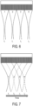
- the transducer elements are divided into a number of subgroups with overlapping elements, and the subgroup that is used to transmit an ultrasound beam is rapidly changed along the lateral direction.
- the result of this "marching" of the subgroup of transducer elements being energized is to provide a focused ultrasound push beam at successively different horizontal locations.
- This technique may be referred to as marching CUSE, or "M-CUSE.”
- a 128 element ultrasound transducer can be divided into four, overlapping subgroups of 64 elements each.
- the first subgroup then transmits a single, focused push beam at a first time, t1.
- the duration of this push beam can be shorter than would be used in F-CUSE or traditional CUSE if it is desirable to control tissue or transducer heating due to repeated transmission using the overlapping transducer elements.
- the push beam duration in M-CUSE can be on the order of 200 ⁇ s.
- the push beam duration is selected based on considerations for how much overlap there is between subgroups of the transducer elements. For instance, the duration can be selected such that any given transducer element in overlapping subgroups is not energized for a consecutive duration that may lead to overheating in that element.
- a second push beam is transmitted at a second time, t2, using the second subgroup of elements. This continues for the third and fourth subgroups.
- shear waves will propagate in soft tissue only about 0.45 mm, which is about 1.5 times the size of an individual transducer element in the transducer.
- the amount of shear wave propagation between successive push beams is negligible for all subgroups after transmitting all of the focused push beams.
- each push beam of the F-CUSE or M-CUSE techniques may have a different number of transmit elements and may be focused at different depths.
- each of the push events for the M-CUSE technique may include using more than one push beams.
- push beams 1 (with less elements) and 2 (with more elements) are simultaneously transmitted at time t 1 , followed by push beams 3 and 4 transmitted simultaneously at time t 2 .
- This combination push will produce strong shear waves at all depths and all lateral positions for shear wave detection and processing.
- push beams in M-CUSE can have different push durations and can be transmitted in an arbitrary order (for example, in a different order 1 ⁇ 4 ⁇ 3 ⁇ 2 compared to the order 1 ⁇ 2 ⁇ 3 ⁇ 4 illustrated in FIG. 7 )
- both F-CUSE and M-CUSE can generate comb-patterned ultrasound push beams that induce a complicated shear wave field with interferences.
- Directional filtering described by Manduca et al. in “SpatioTemporal Directional Filtering for Improved Inversion of MR Elastography Images,” Medical Image Analysis, 2003; 7(4): 465-473 can thus be used to separate the shear waves into multiple directions without interference so that robust shear wave estimates can be achieved at each imaging pixel within the FOV.
- a plane wave imaging mode can be used with all transducer elements delivering ultrasound to detect the propagating shear waves.
- the detection scheme described above can also be used.
Landscapes
- Health & Medical Sciences (AREA)
- Life Sciences & Earth Sciences (AREA)
- Engineering & Computer Science (AREA)
- Physics & Mathematics (AREA)
- Remote Sensing (AREA)
- Radar, Positioning & Navigation (AREA)
- General Health & Medical Sciences (AREA)
- Pathology (AREA)
- General Physics & Mathematics (AREA)
- Animal Behavior & Ethology (AREA)
- Medical Informatics (AREA)
- Molecular Biology (AREA)
- Surgery (AREA)
- Heart & Thoracic Surgery (AREA)
- Biomedical Technology (AREA)
- Public Health (AREA)
- Veterinary Medicine (AREA)
- Radiology & Medical Imaging (AREA)
- Biophysics (AREA)
- Nuclear Medicine, Radiotherapy & Molecular Imaging (AREA)
- Acoustics & Sound (AREA)
- Computer Networks & Wireless Communication (AREA)
- Gynecology & Obstetrics (AREA)
- Biochemistry (AREA)
- Immunology (AREA)
- Analytical Chemistry (AREA)
- Chemical & Material Sciences (AREA)
- Physiology (AREA)
- Computer Vision & Pattern Recognition (AREA)
- Ultra Sonic Daignosis Equipment (AREA)
Claims (7)
- Procédé de mesure d'une propriété mécanique d'un objet à l'aide d'un système à ultrasons doté d'un transducteur à ultrasons qui comporte une pluralité d'éléments de transducteur, le procédé comprenant les étapes suivantes :a) induire de multiples ondes de cisaillement différentes, chaque onde de cisaillement étant générée à l'un d'une pluralité d'endroits spatiaux différents dans l'objet, en utilisant une pluralité de sous-groupes d'éléments de transducteur pour transmettre une pluralité correspondante de faisceaux ultrasonores focalisés, chaque faisceau ultrasonore focalisé étant focalisé à l'un de la pluralité d'endroits spatiaux différents ;b) obtenir des données d'élastographie représentant les multiples ondes de cisaillement différentes en transmettant au moins un faisceau ultrasonore de détection dans l'objet et en recevant des signaux d'écho en réponse à celui-ci dans chacun d'une pluralité d'événements de transmission-détection différents ;c) appliquer un filtre directionnel aux données d'élastographie obtenues pour séparer les multiples ondes de cisaillement différentes en multiples composantes directionnelles différentes afin de réduire les effets d'interférence entre les multiples ondes de cisaillement différentes ; etd) calculer une propriété mécanique de l'objet à l'aide des données d'élastographie obtenues,dans lequel l'étape a) comporte de transmettre un faisceau ultrasonore focalisé à la fois, et dans lequel au moins certains faisceaux ultrasonores focalisés transmis successivement sont générés par(i) des sous-groupes d'éléments de transducteur spatialement adjacents, ou(ii) des sous-groupes d'éléments de transducteur spatialement chevauchants.
- Procédé selon revendication 1, dans lequel l'étape b) comporte :i) de diviser les éléments de transducteur du transducteur à ultrasons en une pluralité de sous-groupes d'éléments de transducteur ;ii) de transmettre successivement un ensemble de faisceaux ultrasonores à l'aide d'un sous-groupe différent d'éléments de transducteur, transmettant ainsi successivement des ultrasons à différentes régions dans l'objet ;iii) de répéter l'étape ii) à une fréquence de répétition d'impulsions telle que chaque ensemble de faisceaux ultrasonores soit effectivement répété à la fréquence de répétition d'impulsions.
- Procédé selon revendication 1, dans lequel l'étape a) comporte de transmettre au moins certains de la pluralité de faisceaux ultrasonores focalisés différents pour les focaliser à des endroits latéraux différents de ceux des autres faisceaux de la pluralité de faisceaux ultrasonores focalisés différents.
- Procédé selon revendication 1, dans lequel l'étape a) comporte de transmettre au moins certains de la pluralité de faisceaux ultrasonores focalisés différents pour les focaliser à des endroits de profondeur différents de ceux des autres faisceaux de pluralité de faisceaux ultrasonores focalisés différents.
- Procédé selon revendication 1, dans lequel la pluralité de faisceaux ultrasonores focalisés différents sont transmis en ensembles séquentiels, dans lequel chaque ensemble contient de multiples faisceaux ultrasonores focalisés générés simultanément qui sont focalisés à différents endroits.
- Procédé selon revendication 1, dans lequel le calcul de la propriété mécanique à l'étape d) comporte d'utiliser au moins un parmi un procédé d'inversion directe et un procédé d'analyse dépendant de la fréquence.
- Procédé selon revendication 1, dans lequel le calcul de la propriété mécanique à l'étape d) comporte de calculer une vitesse d'onde de cisaillement par l'estimation d'un délai entre les points de détection des ondes de cisaillement à l'aide d'au moins un parmi un procédé de corrélation temps-crête et un procédé de corrélation croisée.
Applications Claiming Priority (2)
| Application Number | Priority Date | Filing Date | Title |
|---|---|---|---|
| US201261710744P | 2012-10-07 | 2012-10-07 | |
| PCT/US2013/063631 WO2014055973A1 (fr) | 2012-10-07 | 2013-10-07 | Système et procédé pour l'élastographie par ondes de cisaillement par transmission d'ultrasons avec des sous-groupes d'éléments transducteurs d'ultrasons |
Publications (3)
| Publication Number | Publication Date |
|---|---|
| EP2833792A1 EP2833792A1 (fr) | 2015-02-11 |
| EP2833792A4 EP2833792A4 (fr) | 2016-07-06 |
| EP2833792B1 true EP2833792B1 (fr) | 2024-06-12 |
Family
ID=50435501
Family Applications (1)
| Application Number | Title | Priority Date | Filing Date |
|---|---|---|---|
| EP13844234.8A Active EP2833792B1 (fr) | 2012-10-07 | 2013-10-07 | Procédé pour l'élastographie par ondes de cisaillement par transmission d'ultrasons avec des sous-groupes d'éléments transducteurs d'ultrasons |
Country Status (5)
| Country | Link |
|---|---|
| US (3) | US10624609B2 (fr) |
| EP (1) | EP2833792B1 (fr) |
| JP (1) | JP5973060B2 (fr) |
| CN (1) | CN104363836B (fr) |
| WO (1) | WO2014055973A1 (fr) |
Families Citing this family (35)
| Publication number | Priority date | Publication date | Assignee | Title |
|---|---|---|---|---|
| CN103492855B (zh) * | 2011-02-25 | 2016-03-30 | 梅约医学教育与研究基金会 | 使用非聚焦超声的超声测振 |
| CN105899140B (zh) * | 2013-08-12 | 2019-07-09 | 三星电子株式会社 | 用于产生弹性图像的方法和超声诊断设备 |
| JP6333608B2 (ja) * | 2014-04-16 | 2018-05-30 | キヤノンメディカルシステムズ株式会社 | 超音波診断装置及び制御プログラム |
| GB201410743D0 (en) * | 2014-06-17 | 2014-07-30 | The Technology Partnership Plc | Ablation treatment device sensor |
| JP6420574B2 (ja) * | 2014-06-24 | 2018-11-07 | ジーイー・メディカル・システムズ・グローバル・テクノロジー・カンパニー・エルエルシー | 超音波診断装置及びプログラム |
| US9955950B2 (en) * | 2014-07-30 | 2018-05-01 | General Electric Company | Systems and methods for steering multiple ultrasound beams |
| KR101649273B1 (ko) * | 2014-09-29 | 2016-08-18 | 삼성전자주식회사 | 곡면 프로브를 이용하여 탄성 영상을 생성하는 방법 및 그 의료 영상 장치 |
| US10292682B2 (en) | 2014-09-29 | 2019-05-21 | Samsung Electronics Co., Ltd. | Method and medical imaging apparatus for generating elastic image by using curved array probe |
| JP2017533031A (ja) * | 2014-10-29 | 2017-11-09 | メイヨ フォンデーシヨン フォー メディカル エジュケーション アンド リサーチ | 超音波トランスデューサの連続振動による超音波エラストグラフィのための方法 |
| US9726647B2 (en) * | 2015-03-17 | 2017-08-08 | Hemosonics, Llc | Determining mechanical properties via ultrasound-induced resonance |
| US20180161011A1 (en) * | 2015-06-11 | 2018-06-14 | Koninklijke Philips N.V. | Ultrasonic transducer array probe for shear wave imaging |
| US10729404B2 (en) | 2015-08-03 | 2020-08-04 | Koninklijke Philips N.V. | Ultrasound system and method for measurement using shear wave |
| WO2017062553A1 (fr) | 2015-10-08 | 2017-04-13 | Mayo Foundation For Medical Education And Research | Systèmes et procédés pour élastographie à ultrasons à vibration de transducteur continue |
| US11224409B2 (en) | 2016-03-14 | 2022-01-18 | Mayo Foundation For Medical Education And Research | Shear wave group velocity estimation using spatiotemporal peaks and amplitude thresholding |
| JP6601320B2 (ja) * | 2016-06-16 | 2019-11-06 | コニカミノルタ株式会社 | 超音波診断装置、及び超音波診断装置の制御方法 |
| ES2687485B1 (es) * | 2017-03-24 | 2019-07-31 | Univ Granada | Dispositivo transluminal y procedimiento para la caracterizacion mecanica de estructuras |
| US11534141B2 (en) * | 2017-07-26 | 2022-12-27 | Mayo Foundation For Medical Education And Research | Methods for encoded multi-pulse contrast enhanced ultrasound imaging |
| EP3665475B1 (fr) | 2017-08-10 | 2023-11-29 | Mayo Foundation for Medical Education and Research | Élastographie par ondes de cisaillement à oscillation de sonde ultrasonore |
| EP3447486B1 (fr) * | 2017-08-25 | 2025-05-07 | Kabushiki Kaisha Toshiba | Appareil d'inspection par ultrasons à balayage linéaire et procédé d'inspection par ultrasons à balayage linéaire |
| US11154277B2 (en) | 2017-10-31 | 2021-10-26 | Siemens Medical Solutions Usa, Inc. | Tissue viscoelastic estimation from shear velocity in ultrasound medical imaging |
| CN107970043B (zh) * | 2017-12-28 | 2021-01-19 | 深圳开立生物医疗科技股份有限公司 | 一种剪切波的检测方法及装置 |
| US11452503B2 (en) | 2018-05-18 | 2022-09-27 | Siemens Medical Solutions Usa, Inc. | Shear wave imaging based on ultrasound with increased pulse repetition frequency |
| US11980502B2 (en) | 2018-11-29 | 2024-05-14 | The Penn State Research Foundation | Harmonic shear wave imaging |
| DE102019104679A1 (de) * | 2019-02-25 | 2020-08-27 | GAMPT mbH, Gesellschaft für angewandte medizinische Physik und Technik | Verfahren zur Messzeitverkürzung in der Elastographie |
| US11850098B2 (en) | 2019-06-14 | 2023-12-26 | Echosens | Method and device for measuring an ultrasound parameter of a viscoelastic medium |
| JP2020203078A (ja) * | 2019-06-14 | 2020-12-24 | エコセンス | 粘弾性媒体の超音波パラメータを測定するための方法およびデバイス |
| KR20220035151A (ko) * | 2019-07-15 | 2022-03-21 | 얼테라, 인크 | 초음파 다초점 전단파의 다차원 이미징으로 탄력을 측정하는 시스템 및 장치 |
| CN110720949B (zh) * | 2019-11-12 | 2020-10-30 | 无锡海斯凯尔医学技术有限公司 | 基于超声检测系统的生物体征检测方法 |
| CN110720948B (zh) | 2019-11-12 | 2021-02-02 | 无锡海斯凯尔医学技术有限公司 | 基于超声检测系统的生物体征检测方法 |
| US12352855B2 (en) | 2020-09-04 | 2025-07-08 | Mayo Foundation For Medical Education And Research | Time-aligned plane wave compounding of ultrasound data |
| CN114529492B (zh) * | 2020-10-30 | 2025-02-11 | 深圳迈瑞生物医疗电子股份有限公司 | 一种蠕动波的参数测量方法及超声测量系统 |
| CN113827278B (zh) * | 2021-10-27 | 2023-09-15 | 青岛海信医疗设备股份有限公司 | 剪切波传播速度的确定方法及装置 |
| KR102688130B1 (ko) * | 2021-12-13 | 2024-07-25 | 알피니언메디칼시스템 주식회사 | 전단 파 파라미터 측정 방법 및 초음파 장치 |
| JP7828222B2 (ja) * | 2022-04-07 | 2026-03-11 | 富士フイルム株式会社 | 超音波診断装置及びビーム形成方法 |
| EP4599269A1 (fr) * | 2022-10-03 | 2025-08-13 | Mayo Foundation for Medical Education and Research | Procédé d'imagerie ultrasonore rapide pour une détection de mouvement faisant intervenir des faisceaux de détection en peigne |
Family Cites Families (16)
| Publication number | Priority date | Publication date | Assignee | Title |
|---|---|---|---|---|
| ZA985834B (en) | 1997-07-21 | 1999-01-14 | Henkel Corp | Method for reinforcing structural members |
| US6773399B2 (en) * | 2001-10-20 | 2004-08-10 | Zonare Medical Systems, Inc. | Block-switching in ultrasound imaging |
| US6371912B1 (en) * | 2000-04-05 | 2002-04-16 | Duke University | Method and apparatus for the identification and characterization of regions of altered stiffness |
| FR2902308B1 (fr) * | 2006-06-15 | 2009-03-06 | Echosens Sa | Procede de mesure de proprietes viscoelastiques de tissus biologiques mettant en oeuvre un transducteur ultrasonore |
| EP2146640B1 (fr) * | 2007-05-16 | 2018-05-23 | Super Sonic Imagine | Procédé et dispositif de mesure de la valeur moyenne de la viscoélasticité d'une région d'intérêt |
| US8500639B2 (en) | 2009-09-11 | 2013-08-06 | Mr Holdings (Hk) Limited | Systems and methods for shear wave field formation |
| US10368843B2 (en) * | 2009-11-25 | 2019-08-06 | Koninklijke Philips N.V. | Ultrasonic shear wave imaging with focused scanline beamforming |
| US8753277B2 (en) * | 2009-12-10 | 2014-06-17 | The University Of Rochester | Methods and systems for spatially modulated ultrasound radiation force imaging |
| US9986973B2 (en) * | 2010-04-23 | 2018-06-05 | Mayo Foundation For Medical Education And Research | Method for shear wave ultrasound vibrometry with interleaved push and detection pulses |
| US10576304B2 (en) * | 2010-06-29 | 2020-03-03 | Sunnybrook Research Institute | Thermal therapy apparatus and method using focused ultrasonic sound fields |
| US8668647B2 (en) * | 2010-10-15 | 2014-03-11 | The University Of British Columbia | Bandpass sampling for elastography |
| EP2651307B1 (fr) * | 2010-12-13 | 2017-11-15 | Koninklijke Philips N.V. | Réglage de mesures de force de rayonnement acoustique pour compenser des effets de mouvement d'arrière-plan |
| EP2654552B1 (fr) | 2010-12-22 | 2021-06-23 | Koninklijke Philips N.V. | Estimation de vitesse d'onde de cisaillement à l'aide d'un centre de masse |
| CN103492855B (zh) | 2011-02-25 | 2016-03-30 | 梅约医学教育与研究基金会 | 使用非聚焦超声的超声测振 |
| US8532430B2 (en) * | 2011-07-28 | 2013-09-10 | General Electric Company | Methods for reducing motion artifacts in shear wave images |
| KR20130026327A (ko) * | 2011-09-05 | 2013-03-13 | 삼성전자주식회사 | 초음파 의료 장치 및 이의 제어 방법 |
-
2013
- 2013-10-07 US US14/397,395 patent/US10624609B2/en active Active
- 2013-10-07 JP JP2015511818A patent/JP5973060B2/ja active Active
- 2013-10-07 CN CN201380024980.2A patent/CN104363836B/zh active Active
- 2013-10-07 WO PCT/US2013/063631 patent/WO2014055973A1/fr not_active Ceased
- 2013-10-07 EP EP13844234.8A patent/EP2833792B1/fr active Active
-
2018
- 2018-06-29 US US16/023,782 patent/US11058398B2/en active Active
-
2021
- 2021-07-09 US US17/372,182 patent/US11672508B2/en active Active
Also Published As
| Publication number | Publication date |
|---|---|
| CN104363836A (zh) | 2015-02-18 |
| JP2015515923A (ja) | 2015-06-04 |
| EP2833792A4 (fr) | 2016-07-06 |
| EP2833792A1 (fr) | 2015-02-11 |
| US20150216507A1 (en) | 2015-08-06 |
| US20180317887A1 (en) | 2018-11-08 |
| WO2014055973A1 (fr) | 2014-04-10 |
| US20210338205A1 (en) | 2021-11-04 |
| US11058398B2 (en) | 2021-07-13 |
| CN104363836B (zh) | 2018-05-04 |
| US11672508B2 (en) | 2023-06-13 |
| US10624609B2 (en) | 2020-04-21 |
| JP5973060B2 (ja) | 2016-08-23 |
Similar Documents
| Publication | Publication Date | Title |
|---|---|---|
| US11672508B2 (en) | System and method for shear wave elastography by transmitting ultrasound with subgroups of ultrasound transducer elements | |
| KR101868381B1 (ko) | 의료용 초음파 이미징에서의 전단파 정보의 해석 | |
| US10582911B2 (en) | Adaptive motion estimation in acoustic radiation force imaging | |
| US9907539B2 (en) | Sparse tracking in acoustic radiation force impulse imaging | |
| KR101935514B1 (ko) | 탄성 이미징에서의 주파수 컴파운딩 | |
| US20240245391A1 (en) | Shear wave imaging based on ultrasound with increased pulse repetition interval | |
| KR102164450B1 (ko) | 전단파 이미징을 위한 가변 초점 | |
| KR102319397B1 (ko) | 초음파-기반 전단파 이미징을 위한 각도들 | |
| KR102187153B1 (ko) | 코히어런스를 사용하는 전단 속력 이미징 | |
| CN102551801B (zh) | 对医学超声成像中剪切波信息的求解 | |
| Fouan et al. | Contrast artifact in CPS plane wave imaging using array subapertures |
Legal Events
| Date | Code | Title | Description |
|---|---|---|---|
| PUAI | Public reference made under article 153(3) epc to a published international application that has entered the european phase |
Free format text: ORIGINAL CODE: 0009012 |
|
| 17P | Request for examination filed |
Effective date: 20141106 |
|
| AK | Designated contracting states |
Kind code of ref document: A1 Designated state(s): AL AT BE BG CH CY CZ DE DK EE ES FI FR GB GR HR HU IE IS IT LI LT LU LV MC MK MT NL NO PL PT RO RS SE SI SK SM TR |
|
| AX | Request for extension of the european patent |
Extension state: BA ME |
|
| RIC1 | Information provided on ipc code assigned before grant |
Ipc: A61B 8/08 20060101ALI20151201BHEP Ipc: G01N 29/24 20060101ALI20151201BHEP Ipc: A61N 7/00 20060101ALI20151201BHEP Ipc: A61B 8/00 20060101AFI20151201BHEP Ipc: G01N 29/34 20060101ALI20151201BHEP Ipc: G01S 15/89 20060101ALI20151201BHEP Ipc: G01S 7/52 20060101ALI20151201BHEP |
|
| DAX | Request for extension of the european patent (deleted) | ||
| RA4 | Supplementary search report drawn up and despatched (corrected) |
Effective date: 20160606 |
|
| RIC1 | Information provided on ipc code assigned before grant |
Ipc: G01N 29/24 20060101ALI20160531BHEP Ipc: G01S 15/89 20060101ALI20160531BHEP Ipc: A61N 7/00 20060101ALI20160531BHEP Ipc: G01N 29/34 20060101ALI20160531BHEP Ipc: A61B 8/00 20060101AFI20160531BHEP Ipc: G01S 7/52 20060101ALI20160531BHEP Ipc: A61B 8/08 20060101ALI20160531BHEP |
|
| STAA | Information on the status of an ep patent application or granted ep patent |
Free format text: STATUS: EXAMINATION IS IN PROGRESS |
|
| 17Q | First examination report despatched |
Effective date: 20170711 |
|
| P01 | Opt-out of the competence of the unified patent court (upc) registered |
Effective date: 20230602 |
|
| GRAP | Despatch of communication of intention to grant a patent |
Free format text: ORIGINAL CODE: EPIDOSNIGR1 |
|
| STAA | Information on the status of an ep patent application or granted ep patent |
Free format text: STATUS: GRANT OF PATENT IS INTENDED |
|
| INTG | Intention to grant announced |
Effective date: 20240102 |
|
| RAP3 | Party data changed (applicant data changed or rights of an application transferred) |
Owner name: MAYO FOUNDATION FOR MEDICAL EDUCATION AND RESEARCH |
|
| GRAS | Grant fee paid |
Free format text: ORIGINAL CODE: EPIDOSNIGR3 |
|
| GRAA | (expected) grant |
Free format text: ORIGINAL CODE: 0009210 |
|
| STAA | Information on the status of an ep patent application or granted ep patent |
Free format text: STATUS: THE PATENT HAS BEEN GRANTED |
|
| RIN1 | Information on inventor provided before grant (corrected) |
Inventor name: ZHAO, HENG Inventor name: SONG, PENGFEI Inventor name: CHEN, SHIGAO Inventor name: GREENLEAF, JAMES, F. |
|
| AK | Designated contracting states |
Kind code of ref document: B1 Designated state(s): AL AT BE BG CH CY CZ DE DK EE ES FI FR GB GR HR HU IE IS IT LI LT LU LV MC MK MT NL NO PL PT RO RS SE SI SK SM TR |
|
| REG | Reference to a national code |
Ref country code: GB Ref legal event code: FG4D |
|
| REG | Reference to a national code |
Ref country code: CH Ref legal event code: EP |
|
| REG | Reference to a national code |
Ref country code: IE Ref legal event code: FG4D |
|
| REG | Reference to a national code |
Ref country code: DE Ref legal event code: R096 Ref document number: 602013085796 Country of ref document: DE |
|
| REG | Reference to a national code |
Ref country code: NL Ref legal event code: FP |
|
| PG25 | Lapsed in a contracting state [announced via postgrant information from national office to epo] |
Ref country code: BG Free format text: LAPSE BECAUSE OF FAILURE TO SUBMIT A TRANSLATION OF THE DESCRIPTION OR TO PAY THE FEE WITHIN THE PRESCRIBED TIME-LIMIT Effective date: 20240612 |
|
| PG25 | Lapsed in a contracting state [announced via postgrant information from national office to epo] |
Ref country code: FI Free format text: LAPSE BECAUSE OF FAILURE TO SUBMIT A TRANSLATION OF THE DESCRIPTION OR TO PAY THE FEE WITHIN THE PRESCRIBED TIME-LIMIT Effective date: 20240612 Ref country code: HR Free format text: LAPSE BECAUSE OF FAILURE TO SUBMIT A TRANSLATION OF THE DESCRIPTION OR TO PAY THE FEE WITHIN THE PRESCRIBED TIME-LIMIT Effective date: 20240612 |
|
| REG | Reference to a national code |
Ref country code: LT Ref legal event code: MG9D |
|
| PG25 | Lapsed in a contracting state [announced via postgrant information from national office to epo] |
Ref country code: GR Free format text: LAPSE BECAUSE OF FAILURE TO SUBMIT A TRANSLATION OF THE DESCRIPTION OR TO PAY THE FEE WITHIN THE PRESCRIBED TIME-LIMIT Effective date: 20240913 |
|
| PG25 | Lapsed in a contracting state [announced via postgrant information from national office to epo] |
Ref country code: ES Free format text: LAPSE BECAUSE OF FAILURE TO SUBMIT A TRANSLATION OF THE DESCRIPTION OR TO PAY THE FEE WITHIN THE PRESCRIBED TIME-LIMIT Effective date: 20240612 |
|
| PG25 | Lapsed in a contracting state [announced via postgrant information from national office to epo] |
Ref country code: LV Free format text: LAPSE BECAUSE OF FAILURE TO SUBMIT A TRANSLATION OF THE DESCRIPTION OR TO PAY THE FEE WITHIN THE PRESCRIBED TIME-LIMIT Effective date: 20240612 |
|
| PG25 | Lapsed in a contracting state [announced via postgrant information from national office to epo] |
Ref country code: NO Free format text: LAPSE BECAUSE OF FAILURE TO SUBMIT A TRANSLATION OF THE DESCRIPTION OR TO PAY THE FEE WITHIN THE PRESCRIBED TIME-LIMIT Effective date: 20240912 Ref country code: LV Free format text: LAPSE BECAUSE OF FAILURE TO SUBMIT A TRANSLATION OF THE DESCRIPTION OR TO PAY THE FEE WITHIN THE PRESCRIBED TIME-LIMIT Effective date: 20240612 Ref country code: HR Free format text: LAPSE BECAUSE OF FAILURE TO SUBMIT A TRANSLATION OF THE DESCRIPTION OR TO PAY THE FEE WITHIN THE PRESCRIBED TIME-LIMIT Effective date: 20240612 Ref country code: GR Free format text: LAPSE BECAUSE OF FAILURE TO SUBMIT A TRANSLATION OF THE DESCRIPTION OR TO PAY THE FEE WITHIN THE PRESCRIBED TIME-LIMIT Effective date: 20240913 Ref country code: FI Free format text: LAPSE BECAUSE OF FAILURE TO SUBMIT A TRANSLATION OF THE DESCRIPTION OR TO PAY THE FEE WITHIN THE PRESCRIBED TIME-LIMIT Effective date: 20240612 Ref country code: ES Free format text: LAPSE BECAUSE OF FAILURE TO SUBMIT A TRANSLATION OF THE DESCRIPTION OR TO PAY THE FEE WITHIN THE PRESCRIBED TIME-LIMIT Effective date: 20240612 Ref country code: BG Free format text: LAPSE BECAUSE OF FAILURE TO SUBMIT A TRANSLATION OF THE DESCRIPTION OR TO PAY THE FEE WITHIN THE PRESCRIBED TIME-LIMIT Effective date: 20240612 Ref country code: RS Free format text: LAPSE BECAUSE OF FAILURE TO SUBMIT A TRANSLATION OF THE DESCRIPTION OR TO PAY THE FEE WITHIN THE PRESCRIBED TIME-LIMIT Effective date: 20240912 |
|
| REG | Reference to a national code |
Ref country code: AT Ref legal event code: MK05 Ref document number: 1693527 Country of ref document: AT Kind code of ref document: T Effective date: 20240612 |
|
| PG25 | Lapsed in a contracting state [announced via postgrant information from national office to epo] |
Ref country code: PT Free format text: LAPSE BECAUSE OF FAILURE TO SUBMIT A TRANSLATION OF THE DESCRIPTION OR TO PAY THE FEE WITHIN THE PRESCRIBED TIME-LIMIT Effective date: 20241014 |
|
| PG25 | Lapsed in a contracting state [announced via postgrant information from national office to epo] |
Ref country code: PT Free format text: LAPSE BECAUSE OF FAILURE TO SUBMIT A TRANSLATION OF THE DESCRIPTION OR TO PAY THE FEE WITHIN THE PRESCRIBED TIME-LIMIT Effective date: 20241014 |
|
| PG25 | Lapsed in a contracting state [announced via postgrant information from national office to epo] |
Ref country code: PL Free format text: LAPSE BECAUSE OF FAILURE TO SUBMIT A TRANSLATION OF THE DESCRIPTION OR TO PAY THE FEE WITHIN THE PRESCRIBED TIME-LIMIT Effective date: 20240612 |
|
| PG25 | Lapsed in a contracting state [announced via postgrant information from national office to epo] |
Ref country code: EE Free format text: LAPSE BECAUSE OF FAILURE TO SUBMIT A TRANSLATION OF THE DESCRIPTION OR TO PAY THE FEE WITHIN THE PRESCRIBED TIME-LIMIT Effective date: 20240612 |
|
| PG25 | Lapsed in a contracting state [announced via postgrant information from national office to epo] |
Ref country code: AT Free format text: LAPSE BECAUSE OF FAILURE TO SUBMIT A TRANSLATION OF THE DESCRIPTION OR TO PAY THE FEE WITHIN THE PRESCRIBED TIME-LIMIT Effective date: 20240612 Ref country code: IS Free format text: LAPSE BECAUSE OF FAILURE TO SUBMIT A TRANSLATION OF THE DESCRIPTION OR TO PAY THE FEE WITHIN THE PRESCRIBED TIME-LIMIT Effective date: 20241012 |
|
| PG25 | Lapsed in a contracting state [announced via postgrant information from national office to epo] |
Ref country code: CZ Free format text: LAPSE BECAUSE OF FAILURE TO SUBMIT A TRANSLATION OF THE DESCRIPTION OR TO PAY THE FEE WITHIN THE PRESCRIBED TIME-LIMIT Effective date: 20240612 |
|
| PG25 | Lapsed in a contracting state [announced via postgrant information from national office to epo] |
Ref country code: RO Free format text: LAPSE BECAUSE OF FAILURE TO SUBMIT A TRANSLATION OF THE DESCRIPTION OR TO PAY THE FEE WITHIN THE PRESCRIBED TIME-LIMIT Effective date: 20240612 Ref country code: SK Free format text: LAPSE BECAUSE OF FAILURE TO SUBMIT A TRANSLATION OF THE DESCRIPTION OR TO PAY THE FEE WITHIN THE PRESCRIBED TIME-LIMIT Effective date: 20240612 |
|
| PG25 | Lapsed in a contracting state [announced via postgrant information from national office to epo] |
Ref country code: SM Free format text: LAPSE BECAUSE OF FAILURE TO SUBMIT A TRANSLATION OF THE DESCRIPTION OR TO PAY THE FEE WITHIN THE PRESCRIBED TIME-LIMIT Effective date: 20240612 |
|
| PG25 | Lapsed in a contracting state [announced via postgrant information from national office to epo] |
Ref country code: SM Free format text: LAPSE BECAUSE OF FAILURE TO SUBMIT A TRANSLATION OF THE DESCRIPTION OR TO PAY THE FEE WITHIN THE PRESCRIBED TIME-LIMIT Effective date: 20240612 Ref country code: SK Free format text: LAPSE BECAUSE OF FAILURE TO SUBMIT A TRANSLATION OF THE DESCRIPTION OR TO PAY THE FEE WITHIN THE PRESCRIBED TIME-LIMIT Effective date: 20240612 Ref country code: RO Free format text: LAPSE BECAUSE OF FAILURE TO SUBMIT A TRANSLATION OF THE DESCRIPTION OR TO PAY THE FEE WITHIN THE PRESCRIBED TIME-LIMIT Effective date: 20240612 Ref country code: PL Free format text: LAPSE BECAUSE OF FAILURE TO SUBMIT A TRANSLATION OF THE DESCRIPTION OR TO PAY THE FEE WITHIN THE PRESCRIBED TIME-LIMIT Effective date: 20240612 Ref country code: IS Free format text: LAPSE BECAUSE OF FAILURE TO SUBMIT A TRANSLATION OF THE DESCRIPTION OR TO PAY THE FEE WITHIN THE PRESCRIBED TIME-LIMIT Effective date: 20241012 Ref country code: EE Free format text: LAPSE BECAUSE OF FAILURE TO SUBMIT A TRANSLATION OF THE DESCRIPTION OR TO PAY THE FEE WITHIN THE PRESCRIBED TIME-LIMIT Effective date: 20240612 Ref country code: CZ Free format text: LAPSE BECAUSE OF FAILURE TO SUBMIT A TRANSLATION OF THE DESCRIPTION OR TO PAY THE FEE WITHIN THE PRESCRIBED TIME-LIMIT Effective date: 20240612 Ref country code: AT Free format text: LAPSE BECAUSE OF FAILURE TO SUBMIT A TRANSLATION OF THE DESCRIPTION OR TO PAY THE FEE WITHIN THE PRESCRIBED TIME-LIMIT Effective date: 20240612 |
|
| PG25 | Lapsed in a contracting state [announced via postgrant information from national office to epo] |
Ref country code: IT Free format text: LAPSE BECAUSE OF FAILURE TO SUBMIT A TRANSLATION OF THE DESCRIPTION OR TO PAY THE FEE WITHIN THE PRESCRIBED TIME-LIMIT Effective date: 20240612 |
|
| REG | Reference to a national code |
Ref country code: DE Ref legal event code: R097 Ref document number: 602013085796 Country of ref document: DE |
|
| PG25 | Lapsed in a contracting state [announced via postgrant information from national office to epo] |
Ref country code: DK Free format text: LAPSE BECAUSE OF FAILURE TO SUBMIT A TRANSLATION OF THE DESCRIPTION OR TO PAY THE FEE WITHIN THE PRESCRIBED TIME-LIMIT Effective date: 20240612 |
|
| PLBE | No opposition filed within time limit |
Free format text: ORIGINAL CODE: 0009261 |
|
| STAA | Information on the status of an ep patent application or granted ep patent |
Free format text: STATUS: NO OPPOSITION FILED WITHIN TIME LIMIT |
|
| 26N | No opposition filed |
Effective date: 20250313 |
|
| REG | Reference to a national code |
Ref country code: CH Ref legal event code: PL |
|
| PG25 | Lapsed in a contracting state [announced via postgrant information from national office to epo] |
Ref country code: MC Free format text: LAPSE BECAUSE OF FAILURE TO SUBMIT A TRANSLATION OF THE DESCRIPTION OR TO PAY THE FEE WITHIN THE PRESCRIBED TIME-LIMIT Effective date: 20240612 |
|
| PG25 | Lapsed in a contracting state [announced via postgrant information from national office to epo] |
Ref country code: LU Free format text: LAPSE BECAUSE OF NON-PAYMENT OF DUE FEES Effective date: 20241007 Ref country code: BE Free format text: LAPSE BECAUSE OF NON-PAYMENT OF DUE FEES Effective date: 20241031 |
|
| PG25 | Lapsed in a contracting state [announced via postgrant information from national office to epo] |
Ref country code: CH Free format text: LAPSE BECAUSE OF NON-PAYMENT OF DUE FEES Effective date: 20241031 |
|
| REG | Reference to a national code |
Ref country code: BE Ref legal event code: MM Effective date: 20241031 |
|
| PG25 | Lapsed in a contracting state [announced via postgrant information from national office to epo] |
Ref country code: SE Free format text: LAPSE BECAUSE OF FAILURE TO SUBMIT A TRANSLATION OF THE DESCRIPTION OR TO PAY THE FEE WITHIN THE PRESCRIBED TIME-LIMIT Effective date: 20240612 |
|
| PG25 | Lapsed in a contracting state [announced via postgrant information from national office to epo] |
Ref country code: IE Free format text: LAPSE BECAUSE OF NON-PAYMENT OF DUE FEES Effective date: 20241007 |
|
| PGFP | Annual fee paid to national office [announced via postgrant information from national office to epo] |
Ref country code: NL Payment date: 20251026 Year of fee payment: 13 |
|
| PGFP | Annual fee paid to national office [announced via postgrant information from national office to epo] |
Ref country code: DE Payment date: 20251029 Year of fee payment: 13 |
|
| PGFP | Annual fee paid to national office [announced via postgrant information from national office to epo] |
Ref country code: GB Payment date: 20251027 Year of fee payment: 13 |
|
| PGFP | Annual fee paid to national office [announced via postgrant information from national office to epo] |
Ref country code: FR Payment date: 20251027 Year of fee payment: 13 |
|
| PG25 | Lapsed in a contracting state [announced via postgrant information from national office to epo] |
Ref country code: CY Free format text: LAPSE BECAUSE OF FAILURE TO SUBMIT A TRANSLATION OF THE DESCRIPTION OR TO PAY THE FEE WITHIN THE PRESCRIBED TIME-LIMIT; INVALID AB INITIO Effective date: 20131007 |
|
| PG25 | Lapsed in a contracting state [announced via postgrant information from national office to epo] |
Ref country code: HU Free format text: LAPSE BECAUSE OF FAILURE TO SUBMIT A TRANSLATION OF THE DESCRIPTION OR TO PAY THE FEE WITHIN THE PRESCRIBED TIME-LIMIT; INVALID AB INITIO Effective date: 20131007 |