EP2834411B1 - Tissus de fabrication de papier monocouche pour fabrication de tissu et de produits similaires - Google Patents
Tissus de fabrication de papier monocouche pour fabrication de tissu et de produits similaires Download PDFInfo
- Publication number
- EP2834411B1 EP2834411B1 EP13772299.7A EP13772299A EP2834411B1 EP 2834411 B1 EP2834411 B1 EP 2834411B1 EP 13772299 A EP13772299 A EP 13772299A EP 2834411 B1 EP2834411 B1 EP 2834411B1
- Authority
- EP
- European Patent Office
- Prior art keywords
- fabric
- yarns
- warp
- weft
- pockets
- Prior art date
- Legal status (The legal status is an assumption and is not a legal conclusion. Google has not performed a legal analysis and makes no representation as to the accuracy of the status listed.)
- Active
Links
Images


Classifications
-
- D—TEXTILES; PAPER
- D21—PAPER-MAKING; PRODUCTION OF CELLULOSE
- D21F—PAPER-MAKING MACHINES; METHODS OF PRODUCING PAPER THEREON
- D21F7/00—Other details of machines for making continuous webs of paper
- D21F7/08—Felts
- D21F7/12—Drying
-
- D—TEXTILES; PAPER
- D21—PAPER-MAKING; PRODUCTION OF CELLULOSE
- D21F—PAPER-MAKING MACHINES; METHODS OF PRODUCING PAPER THEREON
- D21F1/00—Wet end of machines for making continuous webs of paper
- D21F1/0027—Screen-cloths
Definitions
- the invention concerns papermaking fabrics for use in forming and conveying high bulk, topographically patterned absorbent paper products such as towel, tissue and similar cellulosic products. It is particularly concerned with such fabrics which are intended for use as forming, transfer or through-air drying (TAD) fabrics in tissue making machines.
- TAD through-air drying
- the majority of towel and tissue products are presently manufactured according to one of either the conventional wet pressing (CWP) or through-air drying (TAD) processes.
- CWP wet pressing
- TAD through-air drying
- a disadvantage of this process is that it densifies the web, decreasing bulk and absorbency in the resultant sheet.
- the TAD process is frequently preferred for the manufacture of tissue and similar cellulosic based absorbent products because it avoids the compressive forces of the dewatering step in the CWP method.
- the wet web is formed by depositing a papermaking furnish onto a moving forming fabric where it is initially drained, and then transferring the resulting very wet web onto a TAD fabric, which is generally of a very open and permeable design.
- the TAD fabric is directed around a permeable drum where the sheet is non-compressively dried by passing hot air through the drum and web while it is held in intimate contact with the fabric.
- the product may then pass over a subsequent Yankee dryer, which is essentially a large steam cylinder with a polished surface, or the Yankee may be omitted.
- Through-air dryers may be used either before or after a Yankee dryer to preserve bulk and increase drying efficiency. It is well known that fabrics having a three-dimensional (i.e. non-planar) product side (PS) surface can introduce protuberances into the sheet which can, in turn, impart significantly increased bulk and absorbent capacity to the resulting paper product.
- PS product side
- the efficiency of the TAD process can be significantly enhanced through the use of single layer, high air permeability fabrics.
- a TAD fabric should ideally have sufficient open area to provide the required air flow to the paper web so as to promote efficient drying.
- the fabric should also have a sufficiently high contact area on its PS to ensure successful transfer of the sheet from the TAD to subsequent dryer elements, such as a Yankee cylinder.
- Fabrics intended for this purpose and which impart a machine direction (MD) oriented pattern in the sheet are generally preferred over those which create a generally cross-machine direction (CD) oriented pattern because this provides the sheet with a smoother "feel", which is desirable in consumer oriented products such as tissue, towel and similar absorbent products.
- An MD oriented pattern in the sheet will require longer MD oriented yarn "floats" in the PS, i.e. areas in the fabric where the MD oriented yarns are not bound by the CD yarns.
- Fabric weave patterns which provide long MD oriented floats will generally also provide higher air permeabilities than patterns which do not.
- TAD fabrics and other papermaking fabrics which are intended to impart a pattern to the paper web formed thereon are well known. See, for example, US 3,301,746 to Sanford et al. ; US 3,603,354 to Lee ; US 3,905,863 to Ayers ; US 4,191,609 and US 4,239,065, both to Trokhan ; US 4,281,688 to Kelly et al. ; US 4,423,755 to Thompson ; US 4,909,284 to Kositzke ; US 4,989,648 , US 4,995,428 and US 4,998,569, all to Tate et al. ; US 5,013,330 and US 5,151,316 to Durkin et al. ; US 5,158,116 to Tate et al. ; US 5,211,815 to Ramasubramanian et al. ; US 5,456,293 and US 5,542,455 both to Ostermayer et al.
- US 7,878,223 to Kroll et al. discloses forming fabrics which utilize a series of two alternating sized pockets for TAD applications.
- the pockets are bounded by raised warp and weft knuckles in the fabric pattern.
- the first pockets are preferably larger in area than the second pockets.
- WO 2008/073301 A2 discloses a machine side layer weave design for use in woven composite papermakers forming fabrics.
- the composite fabric has two sets of weft yarns interwoven with at least one system of warp yarns.
- at least 50% of the warp yarns pass under two adjacent weft yarns on the machine side of the fabric to form a double warp knuckle, and each double warp knuckle is bounded on either side by a single warp knuckle formed on each of the first and second weft passed under by the double warp knuckle.
- each weft yarn is passed under by two adjacent warp yarns to form two adjacent single warp knuckles.
- the knuckles are evenly distributed across the machine side surface.
- the machine side layer weave design is effective in minimizing or eliminating fabric edge curl.
- single layer fabrics can be woven to patterns providing long MD floats, where the warp yarns pass over nine weft yarns, and in which adjacents floats pass together over at least two common weft yarns, and wherein adjacent floats provide elongated pockets therebetween, as defined below.
- such single layer woven fabrics can include a sheet support surface which provides a contact area with the paper sheet that is from at least 20% to 40% or more, which has an air permeability of from at least 500 to 900 cubic feet per ft 2 and per minute (CFM) (9144 to 16458 m 3 /m 2 /hr) or more, and whose sheet support surface is structured and arranged to impart bulk and similar desirable properties in the paper product formed thereon by means of MD oriented yarn floats and pockets.
- CFM cubic feet per ft 2 and per minute
- float refers to the number of successive yarns on the surface of a fabric that a given yarn passes over (or under) without interweaving with another yarn in one repeat of a woven fabric; floats may be formed by either a warp yarn or a weft yarn.
- a warp yarn will interweave with a weft yarn, and then pass over as many as nine successive weft yarns on the sheet support surface of the fabric before it next interweaves with the next weft yarn.
- knuckle refers to the protuberance of a yarn from the surface of the fabric at an interweaving point with a transverse yarn. When a knuckle is formed on the sheet support surface, its prominence is sufficient to form a distinct impression on the sheet being conveyed.
- a “pocket” refers to a depression formed between two warp yarns in the sheet support surface of a fabric, where the depression extends from the top PS surface of a warp yarn knuckle down to the top of a weft yarn in the depression.
- Pocket depth is quantified as the Z-direction distance from the sheet support surface top of a warp yarn at a knuckle to the top of a weft yarn at the bottom center of the adjacent pocket.
- pocket depth is at least equal to the diameter or Z-direction thickness of a warp yarn. Pocket depth can be measured either by microtome sectioning of the fabric, or by electronically scanning the fabric to provide a three dimensional profile.
- sheet support surface refers to the generally planar PS surface of the fabric on which the paper product is formed or conveyed; the opposing surface of the fabric, which is in contact with the various stationary elements or rotating rolls of the machine, is referred to as the "machine side” or MS.
- surfacing refers to an abrasive process in which a portion of a planar surface of a fabric is removed, for example, by means of a rotating sanding roll or similar process. Surfacing removes a portion of the yarn material from the warp and weft yarn knuckles of the fabric. Surfacing is often carried out to increase the contact area between the sheet support surface of a fabric and the paper product it is conveying; surfacing is an optional process.
- MD refers to the machine direction, or direction from the headbox to the reel in which the paper product moves as it passes through the machine
- CD refers to the cross-machine direction, which is perpendicular to the MD in the plane of the paper product.
- caliper refers to the overall average Z-direction thickness of the fabric as measured from the tops of the warp yarn knuckles in the sheet support (PS) surface through to the bottoms of the yarns on the opposite MS fabric surface; fabric caliper is typically measured using a barrel micrometer or similar instrument.
- a "single layer” fabric is one that is woven according to a chosen pattern from single sets of warp and weft yarns, and in which neither the warp nor the weft yarns is stacked in vertical orientation in relation to another of the same yarns in the fabric.
- shed refers to the number of individual heddle frames used in the loom to control the position of the warp yarns as a fabric is woven according to a chosen pattern.
- the fabrics of the present invention are woven according to patterns requiring 10 sheds in the loom, and are thus "10-shed" patterns.
- pattern repeat refers to the unique manner and sequence in which the warp and weft yarns are interlaced (pass over and under one another as the fabric is woven) before the unique interlacing sequence is restarted.
- the pattern repeat requires ten warp yarns and at least ten weft yarns.
- the pattern repeat is sometimes referred to as the "unit cell” in woven cloth as it is the minimum number of uniquely interlaced warp and weft yarns required to produce the entire fabric as woven to the pattern repeat.
- the present invention seeks to provide a woven single layer papermakers' fabric having a sheet support surface and a machine side surface and comprising a set of monofilament machine direction (MD) oriented warp yarns interwoven with a set of monofilament weft yarns in a ten shed repeating weave pattern, wherein in each repeat of the repeating weave pattern, each of the set of monofilament MD oriented warp yarns forms in the sheet support surface at least one long float over nine consecutive weft yarns.
- MD machine direction
- their long floats extend concurrently in the MD for at least 20% of their respective lengths.
- the two warp yarns float concurrently adjacently over at least one group of at least two weft yarns.
- the pockets comprise first and second pockets alternating in the MD, the first pockets being longer in the MD than the second pockets. More preferably, the first pockets extend over six weft yarns and the second pockets extend over two weft yarns.
- the pockets have a maximum pocket depth, as measured from the top of a yarn float on the sheet support surface to the top of a weft yarn below, of about 60% of the fabric caliper.
- the contact area of the sheet support surface is between 20% and 40%, more preferably between 30% and 40%.
- the surfaces of at least some of the warp and weft yarns in the sheet support surface of the fabric comprise abraded areas, and the contact area of the sheet support surface is at least 30%.
- the warp yarns have a cross-sectional shape selected from one of circular, ovate, elliptical, rectangular, trapezoidal and square
- the weft yarns have a cross-sectional shape selected from one of circular, ovate, elliptical, rectangular, trapezoidal and square.
- the warp yarns and the weft yarns each have a circular cross- sectional shape.
- the cross-sectional shape of the warp yarns is rectangular and the cross-sectional shape of the weft yarns is circular.
- the fabrics of the invention have an air permeability of between 500 and 900 cubic feet/ft 2 /min (9144 to 16458 m 3 /m 2 /hr).
- the fabrics of the invention have an open area of between 25% and 40%.
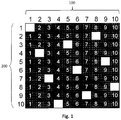
- Figure 1 is a weave diagram showing one pattern repeat of a single layer fabric according to a first embodiment of the invention.
- the warp yarns 100 are numbered 1 to 10 across the top of the pattern, while the weft yarns 200 are numbered 1 to 10 along the left side.
- black squares indicate that a warp yarn is passing over a weft yarn at that location in the fabric as woven, while white squares show that a warp yarn is passing under a weft yarn.
- warp yarn 1 passes under weft yarn 1 to interweave with it, and then floats over weft yarns 2 to 10 to complete the full pattern repeat.
- warp yarn 2 floats over weft yarns 1, 2 and 3, passes under weft yarn 4, then over weft yarns 5 to 10 to complete the repeat.
- All of the warp yarns in the pattern follow paths similar to that described in relation to warp yarns 1 and 2 and all form long floats over nine weft yarns in one repeat of the pattern. The knuckles formed by these long floats create localized protrusions and regions of low fiber density in the sheet being formed or conveyed by the fabric.
- any two adjacent warp yarns such as warp yarns 1 and 2 in Figure 1
- both pass together over two common weft yarns such as weft yarns 2 and 3, before interlacing with a weft yarn to form an MS knuckle.
- the same interweaving occurs throughout the pattern repeat: warp yarns 2 and 3 both pass over weft yarns 5 and 6; warp yarns 3 and 4 both pass over weft yarns 8 and 9, and so on.
- warp yarns 2 and 3 both pass over weft yarns 5 and 6
- FIG 2 is a photograph of the sheet support surface of a fabric 10 woven according to the pattern shown in Figure 1 and showing one pattern repeat of the fabric weave pattern shown in Figure 1 .
- the warp yarns 100 extend vertically and are arranged from left to right in the photograph while the weft yarns 200 extend horizontally and are arranged from top to bottom and are numbered from 201 to 210; there are ten warp yarns 100 and ten weft yarns 200 in Figure 2 ; warp yarns 101, 103, 108 an 109 are identified.
- Each of the warp yarns 100 forms long floats over nine weft yarns 200; warp yarn 101 is exemplary and floats over weft yarns 202 to 210 and then interlaces with weft yarn 201 in the pattern repeat.
- the sheet support surface of the fabric shown in Figure 2 has been surfaced by abrasive means so as to remove a portion of the warp yarn material from the warp knuckles, such as the area shown at 150, where the abraded region is shown as white, and the unabraded portion remains dark, and to remove a portion of the weft yarn material from the weft yarn knuckles, as shown at 220 and 225; this process increases the surface contact area between the paper sheet and fabric.
- surfaced area 150 has had about 0.075 mm of polymeric material removed in the surfacing process; other warp yarns are similar.
- the fabric 10 shown in Figure 2 has an MD contact area (i.e. along the warp yarns 100) of 32.2% and a CD contact area (i.e. along the weft yarns 200) of about 1.1% which together provide for a total fabric contact area between the fabric and sheet of about 33.3%.
- FIG. 2 also shows a further feature of the fabrics of the invention. It can be seen that weft yarn 210 forms a knuckle 220 on warp yarn 108 as it interlaces with that yarn; similarly, weft yarn 207 forms a knuckle 225 as it interlaces with adjacent warp yarn 109. As shown in the area 250, for each of the two adjacent warp yarns 108 and 109, each warp yarn passes over and adjacently overlaps at least two common weft yarns such as 208 and 209 before one of the two warp yarns passes under a weft yarn to form an MS warp knuckle, such as occurs at weft knuckles 220 and 225.
- Figure 3 is an enlarged view of a portion of the fabric shown in Figure 2 and showing a further feature of the fabrics of the present invention regarding the overlap region of two adjacent warp yarn floats.
- the warp yarns such as 110 are oriented vertically and the weft yarns such as 210 are oriented horizontally in the photograph.
- the MD oriented warp yarn floats on any two adjacent warp yarns will be partly concurrent with each other, and be coplanar, over an MD distance equal to at least about 20% of their float length.
- Figure 3 shows one concurrent region of two adjacent warp yarn floats, shown as 120A and 120B in the fabric 10.
- this area of concurrency is indicated by the horizontal lines and vertical arrows presented within the circle 300.
- the warp knuckles 120A and 120B are coplanar with one another.
- the knuckles 120A and 120B are also coplanar with other similar warp knuckles in the sheet support surface of the fabric, regardless of whether or not the fabric has been subjected to a surfacing process.
- the fabric 10 shown in Figures 2 and 3 was woven using circular cross-section 0.35mm diameter polyester terephthalate (PET) warp yarns such as 110, and 0.45mm diameter PET weft yarns such as 210.
- PET polyester terephthalate
- the total length of a warp knuckle, such as 120A or 120B as it floats over nine consecutive weft yarns 210 in the pattern repeat, before interlacing with a tenth weft yarn was measured and found to be about 3.03mm; this warp float length recurs throughout the fabric for all of the warp yarn floats.
- This large coplanar concurrent path of the warp floats in the fabric 10 is desirable as it provides a continuity of MD contact area across the warp yarn floats in the fabric and thus in the paper product conveyed by the fabric which in turn improves the reliability of sheet transfer to subsequent downstream machine sections during the papermaking process.
- Figure 4 illustrates another feature of fabrics made in accordance with the teachings of the present invention.
- Figure 4 is a photograph of the sheet support surface of the fabrics previously presented in Figures 2 and 3 in which two representative pockets 410 and 411 in the sheet support surface are indicated in white with dotted outline and which are located between adjacent warp knuckles 120A, 120B and 120C.
- Pocket 410 which is the larger pocket, is bordered by warp knuckles 120A and 120B, and extends in the MD from sheet support surface weft knuckles 220A to 220B over six weft yarns 203 to 208 in the longitudinal direction of the sheet support surface of fabric 10.
- Pocket 411 which is the smaller pocket, is bordered by warp knuckles 120B and 120C, as well as weft knuckles 220A and 220C and extends over two weft yarns 203 and 204 in the longitudinal direction of fabric 10.
- the warp yarn floats such as 120A, 120B and 120C of adjacent warp yarns form both short pockets such as 411 (between floats 120B and 120C) and long pockets such as 410 (between floats 120A and 120B) throughout the sheet support surface of the fabric.
- each pocket 410 and 411 is the Z-direction distance perpendicular to the plane of the sheet support surface top of a surfaced yarn, such as 120A, to the PS top of the weft yarns, such as weft yarns 203 to 208, which are exposed in the bottom of the pocket and will be at least equal to the thickness, or diameter, of the warp yarns 120A, 120B at that location.
- the depth of pocket 411 will be the Z-direction distance from the top of a warp yarn such as 120B in the sheet support surface to the tops of the exposed weft yarns, such as 203 and 204 in the bottom of the pocket.
- larger pockets such as 410 have an MD length of about 4.23mm and a CD width of about 0.21mm to provide a pocket area of about 0.89mm 2 for each larger pocket in the fabric; as woven there are about 26.5 pockets/cm 2 (171 pockets/in 2 ) similar to larger pocket 410 throughout fabric 10.
- Smaller pocket 411 has an MD length of about 1.56mm, and a CD width of 0.21mm to provide an area of about 0.33mm 2 to the smaller pockets in the fabric; as woven, there are about 26.5 smaller pockets/cm 2 (171 pockets/in 2 ) throughout the fabric.
- the pockets have a depth extending from the top of the sheet support surface into the fabric interior to the PS tops of the weft yarns over which the warp yarns float.
- Pocket depth is defined by the Z-direction distance between the top of the warp yarns in the sheet support surface and the top of the weft yarns at the bottom center of the pocket.
- This feature is illustrated in the photograph shown in Figure 5 which shows a warp yarn such as 110 interwoven with a plurality of weft yarns such as 210 in a cross-section through fabric 10.
- the pocket depth, d is indicated as the distance from the top or maximum height of the warp yarn float to the PS top of the weft yarns 210 at the bottom center of the pocket.
- this distance d is typically about 60% of fabric caliper (fabric thickness) and is at least equal to the thickness, or diameter, of the warp yarns. In the fabric shown in Figure 5 , this depth d measures about 0.686mm (0.027 in.) while the overall fabric caliper is about 1.12mm (0.044 in.).
- FIGS 6A, 6B and 6C are weave diagrams showing one pattern repeat of three further embodiments of fabrics designed in accordance with the teachings of the invention.
- the weft repeat length, or number of weft yarns required in the pattern repeat is twenty yarns as opposed to ten in the design shown in Figure 1 .
- the warp yarns are numbered from 1 to 10 across the top of the weave diagram while the weft yarns are numbered from 1 onwards from the upper left of the design.
- the fabric constructions are all single layer fabrics.
- FIG 6A shows a first alternate embodiment of the invention, in which warp yarn 1 is exemplary.
- warp yarn 1 passes under weft yarn 1 (white square at upper left of pattern), then floats over weft yarns 2 to 10 to pass under weft yarn11.
- warp yarn 1 forms a float over nine consecutive weft yarns, as in the design shown in Figure 1 .
- Warp yarn 1 then floats over weft yarns 12, 13, 14 and 15, passes under weft yarn 16, and then floats over remaining weft yarns 17, 18, 19 and 20 at which point the pattern repeats.
- warp yarn 2 floats over weft yarns 15, 16, 17, 18, 19, 20, 1, 2 and 3 to form a float over nine consecutive weft yarns; warp yarn 2 then passes under weft yarn 4, over weft yarns 5, 6, 7 and 8, under weft yarn 9 and then over weft yarns 10, 11, 12 and 13, and then under weft yarn 14 at which point the pattern repeats.
- the remaining eight warp yarns in the pattern are interwoven in a like manner with the weft yarns.
- FIG. 6B The pattern shown in Figure 6B is similar to that shown in Figure 6A , the main difference being in the paths of warp yarns 1, 3, 5, 7 and 9 which are each shifted in relation to their orientation in Figure 6A .
- warp yarn 1 passes under weft yarn 1, then over weft yarns 2, 3, 4 and 5 to form a four-weft yarn float; it then passes under weft yarn 6, and over weft yarns 7, 8, 9 and 10 to form a second four-weft yarn float.
- Warp yarn 1 then passes under weft yarn 11, and then over all of weft yarns 12 to 20 to form a nine-weft yarn float.
- Warp yarns 3, 5, 7 and 9 follow paths similar to that of warp yarn 1, only each is shifted in relation to warp yarn 1 (e.g. the first interlacing from the top of the pattern for warp yarn 3 is at weft yarn 7 as compared to weft yarn 1 for warp yarn 1, then weft yarn 13 for warp yarn 5, and so on).
- warp yarn 2 floats over weft yarns 15, 16, 17, 18, 19, 20, 1, 2 and 3 to form a float over nine consecutive weft yarns; warp yarn 2 then passes under weft yarn 4, over weft yarns 5, 6, 7 and 8, under weft yarn 9 and then over weft yarns 10, 11, 12 and 13, and then under weft yarn 14 at which point the pattern repeats.
- the path of warp yarns 4, 6, 8 and 10 is identical that of warp yarn 2, only each is shifted down in the pattern repeat by six weft yarns in comparison.
- each of warp yarns 1, 3, 5, 7 and 9 forms two floats over nine consecutive weft yarns in each repeat of the weave pattern.
- warp 1 interweaves with weft 1 and then floats over weft yarns 2 to 10
- floats over weft yarns 12 to 20 to form two long warp floats in one pattern repeat.
- Warp yarn 3 floats over weft yarns 18, 19 and 20, then over weft yarns 1 to 6 to form a first float over nine weft yarns; warp yarn 3 then passes under weft yarn 7 and floats over weft yarns 8 to 16 to form a second float over nine weft yarns.
- the paths of warp yarns 5, 7 and 9 are similar to those of warp yarns 1 and 3, but they are shifted in the pattern in relation to those yarns.
- warp yarns 2, 4, 6, 8 and 10 each form four four-weft yarn floats in the pattern repeat.
- warp yarn 2 passes over weft yarns 20, 1, 2 and 3, under weft yarn 4, over weft yarns 5, 6, 7 and 8 to form a first and second float, under weft yarn 9, over weft yarns 10, 11, 12 and 13 to form a third float, under weft yarn 14, and over weft yarns 15 to 18 to form a fourth float.
- every second warp yarn i.e. 50% of the warp yarns
- forms floats over nine weft yarns while the remainder of the warp yarns form shorter four-weft floats. This may assist to increase the dimensional stability of fabrics woven according to the pattern of Figure 6C .
- the fabrics of the present invention are woven at a mesh (number of warp yarns per unit width) and knocking (number of weft yarns per unit length) that is suitable for their intended end use in the production of tissue and similar products.
- the fabrics of the invention will have an air permeability ranging from about 500 to 900 CFM (about 9144 to 16458 m 3 /m 2 /hr).
- the fabrics will have an open area that may range from about 25% to about 40% and are woven at a mesh (number of warp yarns/unit length) of from 30 yarns/in. to about 80 yarns/in.
- the warp and weft yarn diameters may range from about 0.1 mm to about 1 mm but will ideally be in a range of from about 0.2 mm to about 0.6 mm.
- the fabrics of the present invention are suitable for use in any of the forming, transfer or TAD sections of the papermaking machine as appropriate.
Landscapes
- Woven Fabrics (AREA)
- Paper (AREA)
Claims (12)
- Tissu de fabrication de papier à monocouche tissée (10), présentant une surface de support de feuille et une surface côté machine, comprenant :un jeu de fils de chaîne (101) orientés dans le sens machine (MD) de type monofilament entrelacés avec un jeu de fils de trame (201) de type monofilament suivant un dessin d'armure répétitif, dans lequel dans chaque répétition du dessin d'armure répétitif, chaque fil du jeu de fils de chaîne orientés dans le sens machine (MD) de type monofilament forme dans la surface de support de feuille au moins un flotté long (150) sur neuf fils de trame consécutifs,dans lequelpour chaque deux fils de chaîne adjacents (120A, 120B), dans chaque répétition du dessin d'armure répétitif, les deux fils de chaîne flottent de manière concurrente et adjacente sur au moins un groupe d'au moins deux fils de trame (209, 210) ;pour chaque deux fils de chaîne adjacents (120A, 120B), leurs flottés longs adjacents conjointement aux croisements de trame associés (220A, 220B) définissent une pluralité de poches orientées MD (410, 411) dans la surface de support de feuille,caractérisé en ce quele dessin d'armure répétitif est un dessin d'armure répétitif à 10 foules, etla pluralité de poches orientées MD (410, 411) entre deux fils de chaîne (120A, 120B) comprend un premier jeu de poches (410) et un second jeu de poches, les poches (410) du premier jeu présentant une alternance avec les poches du second jeu dans le MD, les poches (410) du premier jeu étant plus longues dans le MD que les poches du second jeu.
- Tissu (10) selon la revendication 1, caractérisé en ce que les poches du premier jeu de poches (410) s'étendent sur six fils de trame, et les poches du second jeu de poches (411) s'étendent sur deux fils de trame.
- Tissu (10) selon la revendication 1 ou 2, caractérisé en ce que les poches (410, 411) présentent une profondeur de poche maximale, comme mesuré à partir d'un haut d'un flotté de fil sur la surface de support de feuille à un haut d'un fil de trame au-dessous, égale à environ 60 % d'une épaisseur du tissu (10).
- Tissu (10) selon l'une quelconque des revendications 1 à 3, caractérisé en ce qu'une zone de contact de la surface de support de feuille est comprise entre 20 % et 40 %, ou davantage.
- Tissu (10) selon la revendication 4, dans lequel la zone de contact de la surface de support de feuille est comprise entre 30 % et 40 %.
- Tissu (10) selon l'une quelconque des revendications 1 à 3, dans lequel les surfaces d'au moins certains des fils de chaîne (101) et de trame (201) dans la surface de support de feuille du tissu comprennent une pluralité de zones texturées par abrasion, et une zone de contact de la surface de support de feuille est d'au moins 30 %.
- Tissu (10) selon la revendication 1, dans lequel pour chaque deux fils de chaîne adjacents (120A, 120B), leurs flottés longs s'étendent de manière concurrente dans le MD sur au moins 20 % de leurs longueurs respectives.
- Tissu selon l'une quelconque des revendications 1 à 7, dans lequel le jeu de fils de chaîne (101) orientés dans le sens MD de type monofilament présente une forme en coupe transversale parmi une des formes circulaire, ovoïde, elliptique, rectangulaire, trapézoïdale et carrée, et le jeu de fils de trame (201) de type monofilament présente une forme en coupe transversale parmi une des formes circulaire, ovoïde, elliptique, rectangulaire, trapézoïdale et carrée.
- Tissu selon la revendication 8, dans lequel le jeu de fils de chaîne orientés dans le sens MD de type monofilament et le jeu de fils de trame de type monofilament présentent chacun une forme en coupe transversale circulaire.
- Tissu selon la revendication 8, dans lequel la forme en coupe transversale du jeu de fils de chaîne orientés dans le sens MD de type monofilament est rectangulaire, et la forme en coupe transversale du jeu de fils de trame de type monofilament est circulaire.
- Tissu selon l'une quelconque des revendications 1 à 10, présentant une perméabilité à l'air comprise entre 500 et 900 pieds cubes/ft2/min (9144 à 16 459 m3/m2/h).
- Tissu selon l'une quelconque des revendications 1 à 11, présentant une zone ouverte comprise entre 25 % et 40 %.
Applications Claiming Priority (2)
| Application Number | Priority Date | Filing Date | Title |
|---|---|---|---|
| CA2773501A CA2773501A1 (fr) | 2012-04-02 | 2012-04-02 | Tissus monocouches permeables a l'air restant plus secs |
| PCT/CA2013/000280 WO2013149319A1 (fr) | 2012-04-02 | 2013-03-26 | Tissus de fabrication de papier monocouche pour fabrication de tissu et de produits similaires |
Publications (3)
| Publication Number | Publication Date |
|---|---|
| EP2834411A1 EP2834411A1 (fr) | 2015-02-11 |
| EP2834411A4 EP2834411A4 (fr) | 2015-11-25 |
| EP2834411B1 true EP2834411B1 (fr) | 2017-05-31 |
Family
ID=49289833
Family Applications (1)
| Application Number | Title | Priority Date | Filing Date |
|---|---|---|---|
| EP13772299.7A Active EP2834411B1 (fr) | 2012-04-02 | 2013-03-26 | Tissus de fabrication de papier monocouche pour fabrication de tissu et de produits similaires |
Country Status (6)
| Country | Link |
|---|---|
| US (1) | US9062414B2 (fr) |
| EP (1) | EP2834411B1 (fr) |
| CN (1) | CN104204348B (fr) |
| CA (1) | CA2773501A1 (fr) |
| IN (1) | IN2014MN01709A (fr) |
| WO (1) | WO2013149319A1 (fr) |
Families Citing this family (7)
| Publication number | Priority date | Publication date | Assignee | Title |
|---|---|---|---|---|
| US9963831B2 (en) | 2015-06-08 | 2018-05-08 | Gpcp Ip Holdings Llc | Soft absorbent sheets, structuring fabrics for making soft absorbent sheets, and methods of making soft absorbent sheets |
| US10138601B2 (en) | 2015-06-08 | 2018-11-27 | Gpcp Ip Holdings Llc | Soft absorbent sheets, structuring fabrics for making soft absorbent sheets, and methods of making soft absorbent sheets |
| JP6583136B2 (ja) * | 2016-05-11 | 2019-10-02 | 信越化学工業株式会社 | 新規スルホニウム化合物及びその製造方法、レジスト組成物、並びにパターン形成方法 |
| EP3631064B1 (fr) * | 2017-05-30 | 2022-03-30 | AstenJohnson, Inc. | Tissu de séchage à fils de chaîne empilés à stabilité élevée avec flottés de chaîne longs |
| US12553189B2 (en) * | 2019-05-03 | 2026-02-17 | First Quality Tissue, Llc | Absorbent structures with high strength and low MD stretch |
| CN112853798A (zh) * | 2021-03-19 | 2021-05-28 | 西安兴晟生态环境有限公司 | 可生产立体花纹纸的成型网、造纸用抄纸滤筛及造纸机 |
| US12188178B2 (en) * | 2022-12-07 | 2025-01-07 | Voith Patent Gmbh | Structured fabric with discrete elements |
Family Cites Families (41)
| Publication number | Priority date | Publication date | Assignee | Title |
|---|---|---|---|---|
| US3301746A (en) | 1964-04-13 | 1967-01-31 | Procter & Gamble | Process for forming absorbent paper by imprinting a fabric knuckle pattern thereon prior to drying and paper thereof |
| US3573164A (en) | 1967-08-22 | 1971-03-30 | Procter & Gamble | Fabrics with improved web transfer characteristics |
| US3603354A (en) | 1968-04-10 | 1971-09-07 | Huyck Corp | Apparatus for use on papermaking machines |
| US3905863A (en) | 1973-06-08 | 1975-09-16 | Procter & Gamble | Process for forming absorbent paper by imprinting a semi-twill fabric knuckle pattern thereon prior to final drying and paper thereof |
| SE397371C (sv) * | 1976-02-24 | 1980-08-18 | Nordiska Maskinfilt Ab | Formeringsvira for pappers-, cellulosa- eller liknande maskiner |
| CA1071913A (fr) | 1977-03-28 | 1980-02-19 | Robert H. Kositzke | Toile synthetique a coutures rectangulaires pour machine a papier |
| US4290209A (en) | 1978-05-17 | 1981-09-22 | Jwi Ltd. | Dryer fabric |
| US4239065A (en) | 1979-03-09 | 1980-12-16 | The Procter & Gamble Company | Papermachine clothing having a surface comprising a bilaterally staggered array of wicker-basket-like cavities |
| US4191609A (en) | 1979-03-09 | 1980-03-04 | The Procter & Gamble Company | Soft absorbent imprinted paper sheet and method of manufacture thereof |
| US4281688A (en) | 1979-05-01 | 1981-08-04 | Scapa Dryers (Canada) Ltd. | Reversible forming fabric having dominating floats on each face |
| US4438788A (en) | 1980-09-30 | 1984-03-27 | Scapa Inc. | Papermakers belt formed from warp yarns of non-circular cross section |
| US4426795A (en) | 1981-07-31 | 1984-01-24 | Albany International Corp. | Dryer felt fabric and dryer belt |
| US4423755A (en) | 1982-01-22 | 1984-01-03 | Huyck Corporation | Papermakers' fabric |
| CA1277209C (fr) | 1986-11-28 | 1990-12-04 | Dale B. Johnson | Faconnage d'un tissu composite |
| JP2558153B2 (ja) | 1988-08-30 | 1996-11-27 | 日本フイルコン株式会社 | ワイヤマークを改善した単織製紙用織物 |
| JP2558155B2 (ja) | 1988-08-31 | 1996-11-27 | 日本フイルコン株式会社 | 製紙面に補助緯糸の水平面を形成した製紙用一重織物 |
| JP2558154B2 (ja) | 1988-08-31 | 1996-11-27 | 日本フイルコン株式会社 | 製紙面の凹所に補助緯糸を配置した製紙用一重織物 |
| US4909284A (en) | 1988-09-23 | 1990-03-20 | Albany International Corp. | Double layered papermaker's fabric |
| AU628669B2 (en) * | 1989-09-19 | 1992-09-17 | Jwi Ltd. | Press section dewatering fabric |
| US5211815A (en) | 1989-10-30 | 1993-05-18 | James River Corporation | Forming fabric for use in producing a high bulk paper web |
| US5013330A (en) | 1989-12-04 | 1991-05-07 | Asten Group, Inc. | Multi-layered papermakers fabric for thru-dryer application |
| US5151316A (en) | 1989-12-04 | 1992-09-29 | Asten Group, Inc. | Multi-layered papermaker's fabric for thru-dryer application |
| US5103874A (en) | 1990-06-06 | 1992-04-14 | Asten Group, Inc. | Papermakers fabric with stacked machine direction yarns |
| JPH04100955A (ja) | 1990-08-08 | 1992-04-02 | Nippon Oil Co Ltd | 厚地織物用オサ打ち装置 |
| DE4302031C1 (de) * | 1993-01-26 | 1993-12-16 | Heimbach Gmbh Thomas Josef | Trockensieb sowie Verfahren zu dessen Herstellung |
| US5429686A (en) | 1994-04-12 | 1995-07-04 | Lindsay Wire, Inc. | Apparatus for making soft tissue products |
| US5542455A (en) | 1994-08-01 | 1996-08-06 | Wangner Systems Corp. | Papermaking fabric having diagonal rows of pockets separated by diagonal rows of strips having a co-planar surface |
| US5456293A (en) | 1994-08-01 | 1995-10-10 | Wangner Systems Corporation | Woven papermaking fabric with diagonally arranged pockets and troughs |
| US5544678A (en) * | 1995-04-14 | 1996-08-13 | Jwi Ltd. | Composite forming fabric woven with an Nx2N machine side layer |
| US5853547A (en) | 1996-02-29 | 1998-12-29 | Asten, Inc. | Papermaking fabric, process for producing high bulk products and the products produced thereby |
| US6237644B1 (en) | 1998-09-01 | 2001-05-29 | Stewart Lister Hay | Tissue forming fabrics |
| DE19917869C2 (de) | 1999-04-20 | 2003-05-22 | Sca Hygiene Prod Gmbh | Papiermaschinen-Bespannung sowie damit hergestelltes Tissue-Papier |
| US6745797B2 (en) * | 2001-06-21 | 2004-06-08 | Weavexx Corporation | Papermaker's forming fabric |
| US6837276B2 (en) * | 2002-11-07 | 2005-01-04 | Albany International Corp. | Air channel dryer fabric |
| US7300554B2 (en) | 2003-09-11 | 2007-11-27 | Albany International Corp. | Textured surface of a tissue forming fabric to generate bulk, cross directional tensile, absorbency, and softness in a sheet of paper |
| US7585395B2 (en) | 2004-01-30 | 2009-09-08 | Voith Patent Gmbh | Structured forming fabric |
| US7207356B2 (en) | 2004-05-19 | 2007-04-24 | Voith Paper Patent Gmbh | Through air dryer fabric |
| AU2006236320A1 (en) | 2005-04-20 | 2006-10-26 | Albany International Corp. | Through-air-drying fabric |
| US7360560B2 (en) * | 2006-01-31 | 2008-04-22 | Astenjohnson, Inc. | Single layer papermakers fabric |
| WO2008073301A2 (fr) | 2006-12-08 | 2008-06-19 | Astenjohnson, Inc. | Dessin de tissage de couche côté machine pour fabrication de tissus composites |
| US8114254B2 (en) | 2008-07-30 | 2012-02-14 | Voith Patent Gmbh | Structured forming fabric, papermaking machine, and method |
-
2012
- 2012-04-02 CA CA2773501A patent/CA2773501A1/fr not_active Abandoned
-
2013
- 2013-03-26 US US14/388,951 patent/US9062414B2/en active Active
- 2013-03-26 WO PCT/CA2013/000280 patent/WO2013149319A1/fr not_active Ceased
- 2013-03-26 EP EP13772299.7A patent/EP2834411B1/fr active Active
- 2013-03-26 CN CN201380014620.4A patent/CN104204348B/zh not_active Expired - Fee Related
-
2014
- 2014-08-25 IN IN1709MUN2014 patent/IN2014MN01709A/en unknown
Also Published As
| Publication number | Publication date |
|---|---|
| CA2773501A1 (fr) | 2013-10-02 |
| US20150068698A1 (en) | 2015-03-12 |
| WO2013149319A1 (fr) | 2013-10-10 |
| IN2014MN01709A (fr) | 2015-05-29 |
| US9062414B2 (en) | 2015-06-23 |
| EP2834411A4 (fr) | 2015-11-25 |
| EP2834411A1 (fr) | 2015-02-11 |
| CN104204348A (zh) | 2014-12-10 |
| CN104204348B (zh) | 2017-05-24 |
Similar Documents
| Publication | Publication Date | Title |
|---|---|---|
| US7493923B2 (en) | Double layer papermakers fabric with pockets for bulk enhancement | |
| US9422666B2 (en) | Ten-shed semi-duplex through-air dryer fabric | |
| EP2834411B1 (fr) | Tissus de fabrication de papier monocouche pour fabrication de tissu et de produits similaires | |
| EP2140053B1 (fr) | Tissus à séchage par air traversant | |
| US11680369B2 (en) | Woven papermaking fabric including stabilized weave providing textured contacting surface | |
| WO2013023276A1 (fr) | Tissu de gaufrage comprenant des ensembles de fils de chaîne | |
| AU2017386370B2 (en) | Papermaking fabric including textured contacting surface |
Legal Events
| Date | Code | Title | Description |
|---|---|---|---|
| PUAI | Public reference made under article 153(3) epc to a published international application that has entered the european phase |
Free format text: ORIGINAL CODE: 0009012 |
|
| 17P | Request for examination filed |
Effective date: 20141008 |
|
| AK | Designated contracting states |
Kind code of ref document: A1 Designated state(s): AL AT BE BG CH CY CZ DE DK EE ES FI FR GB GR HR HU IE IS IT LI LT LU LV MC MK MT NL NO PL PT RO RS SE SI SK SM TR |
|
| AX | Request for extension of the european patent |
Extension state: BA ME |
|
| RIN1 | Information on inventor provided before grant (corrected) |
Inventor name: CHAPLIN, DEREK |
|
| DAX | Request for extension of the european patent (deleted) | ||
| RA4 | Supplementary search report drawn up and despatched (corrected) |
Effective date: 20151027 |
|
| RIC1 | Information provided on ipc code assigned before grant |
Ipc: D03D 23/00 20060101ALI20151021BHEP Ipc: D21F 7/12 20060101AFI20151021BHEP Ipc: D03D 13/00 20060101ALI20151021BHEP Ipc: D21F 1/10 20060101ALI20151021BHEP |
|
| GRAP | Despatch of communication of intention to grant a patent |
Free format text: ORIGINAL CODE: EPIDOSNIGR1 |
|
| INTG | Intention to grant announced |
Effective date: 20161222 |
|
| RIN1 | Information on inventor provided before grant (corrected) |
Inventor name: CHAPLIN, DEREK |
|
| GRAS | Grant fee paid |
Free format text: ORIGINAL CODE: EPIDOSNIGR3 |
|
| GRAA | (expected) grant |
Free format text: ORIGINAL CODE: 0009210 |
|
| AK | Designated contracting states |
Kind code of ref document: B1 Designated state(s): AL AT BE BG CH CY CZ DE DK EE ES FI FR GB GR HR HU IE IS IT LI LT LU LV MC MK MT NL NO PL PT RO RS SE SI SK SM TR |
|
| REG | Reference to a national code |
Ref country code: CH Ref legal event code: EP Ref country code: GB Ref legal event code: FG4D |
|
| REG | Reference to a national code |
Ref country code: AT Ref legal event code: REF Ref document number: 897589 Country of ref document: AT Kind code of ref document: T Effective date: 20170615 |
|
| REG | Reference to a national code |
Ref country code: IE Ref legal event code: FG4D |
|
| REG | Reference to a national code |
Ref country code: DE Ref legal event code: R096 Ref document number: 602013021756 Country of ref document: DE |
|
| REG | Reference to a national code |
Ref country code: NL Ref legal event code: MP Effective date: 20170531 |
|
| REG | Reference to a national code |
Ref country code: LT Ref legal event code: MG4D |
|
| REG | Reference to a national code |
Ref country code: AT Ref legal event code: MK05 Ref document number: 897589 Country of ref document: AT Kind code of ref document: T Effective date: 20170531 |
|
| PG25 | Lapsed in a contracting state [announced via postgrant information from national office to epo] |
Ref country code: HR Free format text: LAPSE BECAUSE OF FAILURE TO SUBMIT A TRANSLATION OF THE DESCRIPTION OR TO PAY THE FEE WITHIN THE PRESCRIBED TIME-LIMIT Effective date: 20170531 Ref country code: FI Free format text: LAPSE BECAUSE OF FAILURE TO SUBMIT A TRANSLATION OF THE DESCRIPTION OR TO PAY THE FEE WITHIN THE PRESCRIBED TIME-LIMIT Effective date: 20170531 Ref country code: NO Free format text: LAPSE BECAUSE OF FAILURE TO SUBMIT A TRANSLATION OF THE DESCRIPTION OR TO PAY THE FEE WITHIN THE PRESCRIBED TIME-LIMIT Effective date: 20170831 Ref country code: ES Free format text: LAPSE BECAUSE OF FAILURE TO SUBMIT A TRANSLATION OF THE DESCRIPTION OR TO PAY THE FEE WITHIN THE PRESCRIBED TIME-LIMIT Effective date: 20170531 Ref country code: LT Free format text: LAPSE BECAUSE OF FAILURE TO SUBMIT A TRANSLATION OF THE DESCRIPTION OR TO PAY THE FEE WITHIN THE PRESCRIBED TIME-LIMIT Effective date: 20170531 Ref country code: AT Free format text: LAPSE BECAUSE OF FAILURE TO SUBMIT A TRANSLATION OF THE DESCRIPTION OR TO PAY THE FEE WITHIN THE PRESCRIBED TIME-LIMIT Effective date: 20170531 Ref country code: GR Free format text: LAPSE BECAUSE OF FAILURE TO SUBMIT A TRANSLATION OF THE DESCRIPTION OR TO PAY THE FEE WITHIN THE PRESCRIBED TIME-LIMIT Effective date: 20170901 |
|
| PG25 | Lapsed in a contracting state [announced via postgrant information from national office to epo] |
Ref country code: SE Free format text: LAPSE BECAUSE OF FAILURE TO SUBMIT A TRANSLATION OF THE DESCRIPTION OR TO PAY THE FEE WITHIN THE PRESCRIBED TIME-LIMIT Effective date: 20170531 Ref country code: NL Free format text: LAPSE BECAUSE OF FAILURE TO SUBMIT A TRANSLATION OF THE DESCRIPTION OR TO PAY THE FEE WITHIN THE PRESCRIBED TIME-LIMIT Effective date: 20170531 Ref country code: RS Free format text: LAPSE BECAUSE OF FAILURE TO SUBMIT A TRANSLATION OF THE DESCRIPTION OR TO PAY THE FEE WITHIN THE PRESCRIBED TIME-LIMIT Effective date: 20170531 Ref country code: BG Free format text: LAPSE BECAUSE OF FAILURE TO SUBMIT A TRANSLATION OF THE DESCRIPTION OR TO PAY THE FEE WITHIN THE PRESCRIBED TIME-LIMIT Effective date: 20170831 Ref country code: LV Free format text: LAPSE BECAUSE OF FAILURE TO SUBMIT A TRANSLATION OF THE DESCRIPTION OR TO PAY THE FEE WITHIN THE PRESCRIBED TIME-LIMIT Effective date: 20170531 Ref country code: IS Free format text: LAPSE BECAUSE OF FAILURE TO SUBMIT A TRANSLATION OF THE DESCRIPTION OR TO PAY THE FEE WITHIN THE PRESCRIBED TIME-LIMIT Effective date: 20170930 |
|
| REG | Reference to a national code |
Ref country code: FR Ref legal event code: PLFP Year of fee payment: 6 |
|
| PG25 | Lapsed in a contracting state [announced via postgrant information from national office to epo] |
Ref country code: DK Free format text: LAPSE BECAUSE OF FAILURE TO SUBMIT A TRANSLATION OF THE DESCRIPTION OR TO PAY THE FEE WITHIN THE PRESCRIBED TIME-LIMIT Effective date: 20170531 Ref country code: SK Free format text: LAPSE BECAUSE OF FAILURE TO SUBMIT A TRANSLATION OF THE DESCRIPTION OR TO PAY THE FEE WITHIN THE PRESCRIBED TIME-LIMIT Effective date: 20170531 Ref country code: RO Free format text: LAPSE BECAUSE OF FAILURE TO SUBMIT A TRANSLATION OF THE DESCRIPTION OR TO PAY THE FEE WITHIN THE PRESCRIBED TIME-LIMIT Effective date: 20170531 Ref country code: CZ Free format text: LAPSE BECAUSE OF FAILURE TO SUBMIT A TRANSLATION OF THE DESCRIPTION OR TO PAY THE FEE WITHIN THE PRESCRIBED TIME-LIMIT Effective date: 20170531 Ref country code: EE Free format text: LAPSE BECAUSE OF FAILURE TO SUBMIT A TRANSLATION OF THE DESCRIPTION OR TO PAY THE FEE WITHIN THE PRESCRIBED TIME-LIMIT Effective date: 20170531 |
|
| PG25 | Lapsed in a contracting state [announced via postgrant information from national office to epo] |
Ref country code: SM Free format text: LAPSE BECAUSE OF FAILURE TO SUBMIT A TRANSLATION OF THE DESCRIPTION OR TO PAY THE FEE WITHIN THE PRESCRIBED TIME-LIMIT Effective date: 20170531 Ref country code: PL Free format text: LAPSE BECAUSE OF FAILURE TO SUBMIT A TRANSLATION OF THE DESCRIPTION OR TO PAY THE FEE WITHIN THE PRESCRIBED TIME-LIMIT Effective date: 20170531 |
|
| REG | Reference to a national code |
Ref country code: DE Ref legal event code: R097 Ref document number: 602013021756 Country of ref document: DE |
|
| PLBE | No opposition filed within time limit |
Free format text: ORIGINAL CODE: 0009261 |
|
| STAA | Information on the status of an ep patent application or granted ep patent |
Free format text: STATUS: NO OPPOSITION FILED WITHIN TIME LIMIT |
|
| 26N | No opposition filed |
Effective date: 20180301 |
|
| PG25 | Lapsed in a contracting state [announced via postgrant information from national office to epo] |
Ref country code: SI Free format text: LAPSE BECAUSE OF FAILURE TO SUBMIT A TRANSLATION OF THE DESCRIPTION OR TO PAY THE FEE WITHIN THE PRESCRIBED TIME-LIMIT Effective date: 20170531 |
|
| REG | Reference to a national code |
Ref country code: CH Ref legal event code: PL |
|
| PG25 | Lapsed in a contracting state [announced via postgrant information from national office to epo] |
Ref country code: MC Free format text: LAPSE BECAUSE OF FAILURE TO SUBMIT A TRANSLATION OF THE DESCRIPTION OR TO PAY THE FEE WITHIN THE PRESCRIBED TIME-LIMIT Effective date: 20170531 |
|
| REG | Reference to a national code |
Ref country code: BE Ref legal event code: MM Effective date: 20180331 |
|
| REG | Reference to a national code |
Ref country code: IE Ref legal event code: MM4A |
|
| PG25 | Lapsed in a contracting state [announced via postgrant information from national office to epo] |
Ref country code: LU Free format text: LAPSE BECAUSE OF NON-PAYMENT OF DUE FEES Effective date: 20180326 |
|
| PG25 | Lapsed in a contracting state [announced via postgrant information from national office to epo] |
Ref country code: IE Free format text: LAPSE BECAUSE OF NON-PAYMENT OF DUE FEES Effective date: 20180326 |
|
| PG25 | Lapsed in a contracting state [announced via postgrant information from national office to epo] |
Ref country code: CH Free format text: LAPSE BECAUSE OF NON-PAYMENT OF DUE FEES Effective date: 20180331 Ref country code: BE Free format text: LAPSE BECAUSE OF NON-PAYMENT OF DUE FEES Effective date: 20180331 Ref country code: LI Free format text: LAPSE BECAUSE OF NON-PAYMENT OF DUE FEES Effective date: 20180331 |
|
| PG25 | Lapsed in a contracting state [announced via postgrant information from national office to epo] |
Ref country code: MT Free format text: LAPSE BECAUSE OF NON-PAYMENT OF DUE FEES Effective date: 20180326 |
|
| PG25 | Lapsed in a contracting state [announced via postgrant information from national office to epo] |
Ref country code: TR Free format text: LAPSE BECAUSE OF FAILURE TO SUBMIT A TRANSLATION OF THE DESCRIPTION OR TO PAY THE FEE WITHIN THE PRESCRIBED TIME-LIMIT Effective date: 20170531 |
|
| PG25 | Lapsed in a contracting state [announced via postgrant information from national office to epo] |
Ref country code: PT Free format text: LAPSE BECAUSE OF FAILURE TO SUBMIT A TRANSLATION OF THE DESCRIPTION OR TO PAY THE FEE WITHIN THE PRESCRIBED TIME-LIMIT Effective date: 20170531 |
|
| PG25 | Lapsed in a contracting state [announced via postgrant information from national office to epo] |
Ref country code: HU Free format text: LAPSE BECAUSE OF FAILURE TO SUBMIT A TRANSLATION OF THE DESCRIPTION OR TO PAY THE FEE WITHIN THE PRESCRIBED TIME-LIMIT; INVALID AB INITIO Effective date: 20130326 Ref country code: MK Free format text: LAPSE BECAUSE OF NON-PAYMENT OF DUE FEES Effective date: 20170531 Ref country code: CY Free format text: LAPSE BECAUSE OF FAILURE TO SUBMIT A TRANSLATION OF THE DESCRIPTION OR TO PAY THE FEE WITHIN THE PRESCRIBED TIME-LIMIT Effective date: 20170531 |
|
| PG25 | Lapsed in a contracting state [announced via postgrant information from national office to epo] |
Ref country code: AL Free format text: LAPSE BECAUSE OF FAILURE TO SUBMIT A TRANSLATION OF THE DESCRIPTION OR TO PAY THE FEE WITHIN THE PRESCRIBED TIME-LIMIT Effective date: 20170531 |
|
| PGFP | Annual fee paid to national office [announced via postgrant information from national office to epo] |
Ref country code: GB Payment date: 20260211 Year of fee payment: 14 |
|
| PGFP | Annual fee paid to national office [announced via postgrant information from national office to epo] |
Ref country code: DE Payment date: 20260213 Year of fee payment: 14 |
|
| PGFP | Annual fee paid to national office [announced via postgrant information from national office to epo] |
Ref country code: IT Payment date: 20260310 Year of fee payment: 14 |
|
| PGFP | Annual fee paid to national office [announced via postgrant information from national office to epo] |
Ref country code: FR Payment date: 20260209 Year of fee payment: 14 |