EP2834440B1 - Dispositif de support réglable pour un cadre et méthode d'installation - Google Patents
Dispositif de support réglable pour un cadre et méthode d'installation Download PDFInfo
- Publication number
- EP2834440B1 EP2834440B1 EP12708019.0A EP12708019A EP2834440B1 EP 2834440 B1 EP2834440 B1 EP 2834440B1 EP 12708019 A EP12708019 A EP 12708019A EP 2834440 B1 EP2834440 B1 EP 2834440B1
- Authority
- EP
- European Patent Office
- Prior art keywords
- adjustable support
- foundation
- support device
- frame member
- stem
- Prior art date
- Legal status (The legal status is an assumption and is not a legal conclusion. Google has not performed a legal analysis and makes no representation as to the accuracy of the status listed.)
- Active
Links
Images

Classifications
-
- E—FIXED CONSTRUCTIONS
- E06—DOORS, WINDOWS, SHUTTERS, OR ROLLER BLINDS IN GENERAL; LADDERS
- E06B—FIXED OR MOVABLE CLOSURES FOR OPENINGS IN BUILDINGS, VEHICLES, FENCES OR LIKE ENCLOSURES IN GENERAL, e.g. DOORS, WINDOWS, BLINDS, GATES
- E06B1/00—Border constructions of openings in walls, floors, or ceilings; Frames to be rigidly mounted in such openings
- E06B1/56—Fastening frames to the border of openings or to similar contiguous frames
- E06B1/60—Fastening frames to the border of openings or to similar contiguous frames by mechanical means, e.g. anchoring means
- E06B1/6069—Separate spacer means acting exclusively in the plane of the opening; Shims; Wedges; Tightening of a complete frame inside a wall opening
- E06B1/6076—Separate spacer means acting exclusively in the plane of the opening; Shims; Wedges; Tightening of a complete frame inside a wall opening of screw-type
-
- E—FIXED CONSTRUCTIONS
- E06—DOORS, WINDOWS, SHUTTERS, OR ROLLER BLINDS IN GENERAL; LADDERS
- E06B—FIXED OR MOVABLE CLOSURES FOR OPENINGS IN BUILDINGS, VEHICLES, FENCES OR LIKE ENCLOSURES IN GENERAL, e.g. DOORS, WINDOWS, BLINDS, GATES
- E06B1/00—Border constructions of openings in walls, floors, or ceilings; Frames to be rigidly mounted in such openings
- E06B1/04—Frames for doors, windows, or the like to be fixed in openings
-
- E—FIXED CONSTRUCTIONS
- E06—DOORS, WINDOWS, SHUTTERS, OR ROLLER BLINDS IN GENERAL; LADDERS
- E06B—FIXED OR MOVABLE CLOSURES FOR OPENINGS IN BUILDINGS, VEHICLES, FENCES OR LIKE ENCLOSURES IN GENERAL, e.g. DOORS, WINDOWS, BLINDS, GATES
- E06B1/00—Border constructions of openings in walls, floors, or ceilings; Frames to be rigidly mounted in such openings
- E06B1/56—Fastening frames to the border of openings or to similar contiguous frames
- E06B1/60—Fastening frames to the border of openings or to similar contiguous frames by mechanical means, e.g. anchoring means
- E06B1/6015—Anchoring means
- E06B1/6023—Anchoring means completely hidden between the frame and the border of the opening, at least part of the means being previously fixed to the wall
- E06B1/603—Anchoring means completely hidden between the frame and the border of the opening, at least part of the means being previously fixed to the wall adjustable
-
- E—FIXED CONSTRUCTIONS
- E06—DOORS, WINDOWS, SHUTTERS, OR ROLLER BLINDS IN GENERAL; LADDERS
- E06B—FIXED OR MOVABLE CLOSURES FOR OPENINGS IN BUILDINGS, VEHICLES, FENCES OR LIKE ENCLOSURES IN GENERAL, e.g. DOORS, WINDOWS, BLINDS, GATES
- E06B7/00—Special arrangements or measures in connection with doors or windows
Definitions
- the invention concerns an adjustable support device which with suitable accessories may be used for adjusting the height, level and sideways clearance when installing windows and doors in various building constructions. More specifically, the invention concerns an adjustable support device for a frame member, comprising a stem having fastening means for releasably connecting the stem to a foundation, and the adjustable support device also comprising a support element for the frame member, connected to one end of the stem, and a method of supporting and adjusting a frame member with respect to a foundation, by using at least two adjustable support devices according to the invention.
- the state of the art involves using wedges made of wood or plastic as frame supports and adjustment means, an example of which is illustrated in figure 1 .
- the wedges 17 are inserted towards each other, one from each side of the bottom frame member 8 frame or side frame members 18 of the window 16, and pushed towards each other until the desired height adjustment and level has been obtained.
- the wedges 17 are normally fixed by a nail, extending through the wedges and into the foundation 10. If the wedges are too long, compared to the width of the foundation, they must be cut following installation.
- Each assembly of wedges 17 occupies a significant volume between the foundation and the frame; these volumes cannot be insulated and are hence in effect thermal bridges in the finished building construction. This gives a higher U-value (a measure of the rate of heat loss through a material) than what is desired.
- the state of the art includes NO 315431, which discloses an adjustable fastener for joining a window frame to a surrounding stationary building structure.
- the fastener comprises an externally threaded bushing which is designed to be screwed into a pre-drilled hole through the frame.
- a combined fastening and support screw fits inside the bushing, and the frame may thus be levelled by rotating the screw.
- NO 142823 , DE 7128103 and EP 0878591 all disclose fasteners for door frames.
- GB 2131113 A which discloses a bolt and EP 899407 A1 which discloses a screw with a tiltable support plate.
- an adjustable support device for a frame member comprising a stem having fastening means for releasably connecting the stem to a foundation, and the adjustable support device also comprising a support element for the frame member, connected to one end of the stem.
- the adjustable support device is characterized by a tool interface portion which is accessible for an operating tool when the frame member is resting on the support element and configured such that the distance between the foundation and the frame member may be adjusted by the operating tool when a frame member is resting on the support element.
- the tool interface portion comprises at least one pair of parallel, opposing faces which are configured for connection to the operating tool.
- the support element is a plate member and the tool interface portion is arranged on an edge of the plate member.
- the adjustable support device preferably comprises distance indication means for indicating the distance between the foundation and the frame member.
- the distance indication means are in one embodiment markings at regular intervals on the stem.
- the support element comprises a recessed portion configured for connection to a screw driver, bit or similar, and the recessed portion is arranged in the part of the support element which is configured for abutting against the frame member.
- the invention makes it possible to adjust the height of the adjustable support device with respect to the support even when a frame is resting on the support element.
- FIG 2 is a perspective view of an embodiment of the adjustable support device 1 according to the invention.
- the device which in the following also will be referred to as an adjustment screw 1, comprises a stem 2a with external threads 1b and a pointed end 6.
- the stem is dimensioned for the weight which the screw is intended to carry and configured for connection to the applicable foundation.
- the materials of the foundation may typically be wood, Siporex , metal, Leca (" Light Expanded Clay Aggregate”) , brick or concrete.
- the adjustment screw 1 furthermore comprises a support plate 3 and an interface portion 4 for a screw driver (not shown) or similar.
- the interface portion 4 is in the form of a recessed hexagonal receptacle for a bit or screw driver.
- the support plate 3 comprises an edge 7 configured for interface with a suitable operating tool 15 (see figure 5 ); the figures illustrating an octagonal edge 7 having pairs of parallel and opposing faces 7a.
- the support plate 3 is dimensioned according to relevant weight and surface area requirements.
- the upper part of the stem 2a comprises distance indicator markings 5, whereby the operator visually may verify the height of the support plate, i.e. its distance from the foundation.
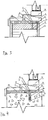
- Figure 3 is a horizontal view of the adjustment screw in use for supporting and adjusting a window having a bottom frame member 8.
- the stem 2a extends into a foundation of wood 10 and allows an external seal 9 to be fitted around the frame, and insulation 12 to be distributed evenly between the foundation 10 and the bottom frame member 8.
- Reference number 11 indicates external panelling. The invention thus provides for a better U-value than that of the prior art ( figure 1 ).
- the stem 2a extends into a plug 14 which has been inserted into a pre-drilled hole in a foundation of concrete 13. Similar to the configuration illustrated by figure 3 , the invention allows an external seal 9 to be fitted around the frame, and insulation 12 to be distributed evenly between the foundation 10 and the bottom frame member 8. The invention thus provides for a better U-value that that of the prior art ( figure 1 ).
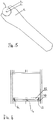
- FIG 5 illustrates an operating tool (or key) 15, connected to the octagonal edge 7 of the support plate 3.
- the operating tool 15 may easily be inserted between the bottom frame member 8 and the wood foundation 10 (or concrete foundation 13) and connected to the edge 7 even when the support plate 3 supports a frame. The height and/or level of the frame (and hence the window or door, etc.) may thus easily be adjusted.
- FIG 6 illustrates a method of using the adjustment screw.
- Adjustment screws 1a-c are fastened to the wood foundation 10, e.g. by means of a driving bit connected to the interface 4 (see figure 2 ).
- one screw 1a,b is positioned at each reveal (corner) and one screw 1c in the middle.
- the first screw 1a is adjusted to the desired level, e.g. by using the distance indicators 15.
- a second screws 1b is installed, a level 19 is placed on top of the screws' support plates 3, and each adjustment screw 1a-c is adjusted (by the tool 15; see figure 5 ) until the level is correct.
- the window or door may then be installed in a level frame.
Landscapes
- Engineering & Computer Science (AREA)
- Civil Engineering (AREA)
- Structural Engineering (AREA)
- Mechanical Engineering (AREA)
- Door And Window Frames Mounted To Openings (AREA)
Claims (6)
- Dispositif de support réglable (1) destiné à un élément de cadre (8), comprenant une tige (2a) ayant des moyens de fixation (2b, 6) destinés à relier de manière amovible la tige à un socle (10, 13), le dispositif de support réglable comprenant en outre un élément de support (3) destiné à l'élément de cadre, relié à une extrémité de la tige, le dispositif de support réglable (1) comprenant en outre une partie d'interface d'outil (7) accessible pour un outil fonctionnel (15) lorsque l'élément de cadre repose sur l'élément de support (3) et est configuré de sorte que la distance entre le socle et l'élément de cadre puisse être réglée par l'outil fonctionnel lorsqu'un élément de cadre repose sur l'élément de support,
caractérisé en ce que la partie supérieure de la tige (2a) comprend en outre un moyen d'indication de distance (5) prévu entre les moyens de fixation (2b, 6) et l'élément de support (3) afin d'indiquer une distance souhaitée entre le socle et le cadre lorsque le cadre est placé sur l'élément de support. - Dispositif de support réglable selon la revendication 1, dans lequel la partie d'interface d'outil (7) comprend au moins une paire de faces opposées parallèles (7a) qui sont configurées pour être reliées à l'outil fonctionnel (15).
- Dispositif de support réglable selon la revendication 1 ou 2, dans lequel l'élément de support (3) est un élément de plaque et la partie d'interface d'outil (7) est prévue sur un bord de l'élément de plaque.
- Dispositif de support réglable selon la revendication 1, dans lequel le moyen d'indication de distance (5) comprend des marquages à des intervalles réguliers sur la tige.
- Dispositif de support réglable selon l'une quelconque des revendications précédentes, dans lequel l'élément de support comprend une partie renfoncée (4) configurée pour être reliée à un tournevis, un foret ou un instrument similaire, et la partie renfoncée est prévue dans la partie de l'élément de support qui est configurée pour buter contre l'élément de cadre.
- Procédé de support et de réglage d'un élément de cadre (8) par rapport à un socle (10, 13) en utilisant au moins deux dispositifs de support réglables (1 a, 1 b) selon l'une quelconque des revendications 1 à 5,
caractérisé en ce que le procédé comprend les étapes consistant à :a) installer un premier dispositif de support réglable (1a) en vissant ou en insérant sa tige à une distance souhaitée à l'intérieur du socle, à l'aide du moyen d'indication de distance (5) ;b) installer un second dispositif de support réglable (1 b) en vissant ou en insérant sa tige sur une distance souhaitée à l'intérieur du socle, à l'aide du moyen d'indication de distance (5) ;c) placer un niveau (19) au-dessus des plaques de support (3) du premier et du second dispositifs de support réglables ;d) régler la distance entre le socle (10, 13) et l'élément de support (3) des dispositifs de support réglables (1a, 1b) jusqu'à ce que le niveau adéquat soit atteint.
Applications Claiming Priority (1)
| Application Number | Priority Date | Filing Date | Title |
|---|---|---|---|
| PCT/EP2012/054026 WO2013131572A1 (fr) | 2012-03-08 | 2012-03-08 | Dispositif de support réglable pour un élément de châssis et procédé d'installation |
Publications (2)
| Publication Number | Publication Date |
|---|---|
| EP2834440A1 EP2834440A1 (fr) | 2015-02-11 |
| EP2834440B1 true EP2834440B1 (fr) | 2017-05-03 |
Family
ID=45812781
Family Applications (1)
| Application Number | Title | Priority Date | Filing Date |
|---|---|---|---|
| EP12708019.0A Active EP2834440B1 (fr) | 2012-03-08 | 2012-03-08 | Dispositif de support réglable pour un cadre et méthode d'installation |
Country Status (5)
| Country | Link |
|---|---|
| US (1) | US20150075091A1 (fr) |
| EP (1) | EP2834440B1 (fr) |
| CN (1) | CN104302860A (fr) |
| CA (1) | CA2903902C (fr) |
| WO (1) | WO2013131572A1 (fr) |
Families Citing this family (2)
| Publication number | Priority date | Publication date | Assignee | Title |
|---|---|---|---|---|
| CN104712220B (zh) * | 2015-03-19 | 2017-03-08 | 常州玖洲联横建材有限公司 | 一种附框连接件及其安装方法 |
| CN113417542B (zh) * | 2021-07-16 | 2022-05-03 | 北京建筑大学 | 一种适用于保护历史建筑的双层窗户 |
Citations (6)
| Publication number | Priority date | Publication date | Assignee | Title |
|---|---|---|---|---|
| GB2131113A (en) | 1982-11-25 | 1984-06-13 | Chang Chung Hsing | Bolt driving formation |
| US4856241A (en) | 1985-09-09 | 1989-08-15 | Lars Lagergren | Device for fastening doors and windows to a wall opening |
| KR100762784B1 (ko) | 2007-01-08 | 2007-10-02 | (주)좋은문 | 문틀 고정 장치 |
| US20100209213A1 (en) | 2009-02-17 | 2010-08-19 | Savio S.P.A. | System for fastening accessories on frames made of metal material for doors, windows, and the like |
| CN201775689U (zh) | 2010-08-23 | 2011-03-30 | 阎京如 | 一种牙科人工植体 |
| US20110112436A1 (en) | 2009-11-06 | 2011-05-12 | SpineSmith Partners, LP | Distraction pins for fluid aspiration |
Family Cites Families (26)
| Publication number | Priority date | Publication date | Assignee | Title |
|---|---|---|---|---|
| DE7128103U (de) | 1971-10-28 | Fitzner A | Befestigungseinrichtung für Blockfutter, insbesondere von Türrahmen | |
| US2764886A (en) * | 1951-04-10 | 1956-10-02 | Robertson Co H H | Identification device for the wiring cells of a floor |
| US2940784A (en) * | 1956-06-06 | 1960-06-14 | William B Fell | Precision threaded adjustment |
| IT1035892B (it) * | 1974-06-05 | 1979-10-20 | Hulinsky J | Dispositivo e procedimento per il fissaggio di intelaiature di porte e finestre |
| US4450834A (en) * | 1979-10-18 | 1984-05-29 | Ace Orthopedic Manufacturing, Inc. | External fixation device |
| US4397124A (en) * | 1981-06-10 | 1983-08-09 | Kawneer Company, Inc. | Glass jacks for doors, windows, walls, etc. |
| US4635414A (en) * | 1982-09-15 | 1987-01-13 | Allen Ernest R | Adjustable door jamb leveler |
| US5180388A (en) * | 1990-06-28 | 1993-01-19 | American Cyanamid Company | Bone pinning system |
| US5511760A (en) * | 1993-11-02 | 1996-04-30 | Kambara; Goro | Post installable self locking machine leveling device |
| DE19720879A1 (de) | 1997-05-17 | 1998-11-19 | Adolf Wuerth Gmbh & Co Kg | Vorrichtung zur Befestigung eines Holzelementes |
| US5895389A (en) * | 1997-05-29 | 1999-04-20 | Synthes (U.S.A.) | Drilling guide and measuring instrumentation |
| EP0899407A1 (fr) * | 1997-09-01 | 1999-03-03 | GLUSA, Dieter | Dispositif de support et de fixation pour la fixation d'un dormant d'une fenêtre ou d'une porte dans l'ouverture d'un mur d'un bâtiment |
| US6308476B1 (en) * | 1998-08-25 | 2001-10-30 | Kabushiki Kaisha Juken Sangyo | Adjustable frame |
| US6185870B1 (en) * | 1999-08-06 | 2001-02-13 | Stafast Products, Inc. | Adjustable threshold assembly |
| DE19948543A1 (de) * | 1999-09-22 | 2001-04-26 | Andreas Stroeber | Vorrichtung für Fenster- oder Türrahmen zu deren Justage beim Einbau in Mauer- oder dergleichen Wandöffnungen und Verfahren zur Herstellung von Fensterrahmen |
| DE10202029A1 (de) * | 2002-01-18 | 2003-07-24 | Bayerwald Fenster Und Haustuer | Vorrichtung zum Einbau von Türen |
| US6951562B2 (en) * | 2002-11-13 | 2005-10-04 | Ralph Fritz Zwirnmann | Adjustable length tap and method for drilling and tapping a bore in bone |
| US7210382B2 (en) * | 2005-08-15 | 2007-05-01 | Eastway Fair Company Ltd. | Screw guide device |
| US7987637B2 (en) * | 2006-09-25 | 2011-08-02 | Smith Patrick J | Adjustable shim |
| US7481253B2 (en) * | 2006-10-02 | 2009-01-27 | Woodpeckers, Inc. | Adjustable scale and router table for use therewith |
| US20100257789A1 (en) * | 2009-04-09 | 2010-10-14 | Quanex Building Products Corporation | Seal for an adjustable threshold assembly |
| DE202009015144U1 (de) * | 2009-11-06 | 2010-03-18 | Weber, Josef | Schraubvorrichtung |
| NZ574949A (en) * | 2010-01-12 | 2011-04-29 | Pranesh Kumar | Cannulated surgical drill with depth gauge |
| US8806812B2 (en) * | 2010-01-27 | 2014-08-19 | Black Mountain Door, Llc | Adjustable door frame assembly and method of installation |
| US9308080B2 (en) * | 2010-03-10 | 2016-04-12 | Smith & Nephew Inc. | Composite interference screws and drivers |
| JP5855925B2 (ja) * | 2011-12-13 | 2016-02-09 | 株式会社屋根技術研究所 | 支持瓦 |
-
2012
- 2012-03-08 CA CA2903902A patent/CA2903902C/fr active Active
- 2012-03-08 US US14/382,556 patent/US20150075091A1/en not_active Abandoned
- 2012-03-08 WO PCT/EP2012/054026 patent/WO2013131572A1/fr not_active Ceased
- 2012-03-08 CN CN201280071276.8A patent/CN104302860A/zh active Pending
- 2012-03-08 EP EP12708019.0A patent/EP2834440B1/fr active Active
Patent Citations (6)
| Publication number | Priority date | Publication date | Assignee | Title |
|---|---|---|---|---|
| GB2131113A (en) | 1982-11-25 | 1984-06-13 | Chang Chung Hsing | Bolt driving formation |
| US4856241A (en) | 1985-09-09 | 1989-08-15 | Lars Lagergren | Device for fastening doors and windows to a wall opening |
| KR100762784B1 (ko) | 2007-01-08 | 2007-10-02 | (주)좋은문 | 문틀 고정 장치 |
| US20100209213A1 (en) | 2009-02-17 | 2010-08-19 | Savio S.P.A. | System for fastening accessories on frames made of metal material for doors, windows, and the like |
| US20110112436A1 (en) | 2009-11-06 | 2011-05-12 | SpineSmith Partners, LP | Distraction pins for fluid aspiration |
| CN201775689U (zh) | 2010-08-23 | 2011-03-30 | 阎京如 | 一种牙科人工植体 |
Also Published As
| Publication number | Publication date |
|---|---|
| CA2903902C (fr) | 2017-11-14 |
| CN104302860A (zh) | 2015-01-21 |
| EP2834440A1 (fr) | 2015-02-11 |
| CA2903902A1 (fr) | 2013-09-12 |
| WO2013131572A1 (fr) | 2013-09-12 |
| US20150075091A1 (en) | 2015-03-19 |
Similar Documents
| Publication | Publication Date | Title |
|---|---|---|
| US7908804B2 (en) | Structural lintel assembly and building construction method using the same | |
| US8826629B1 (en) | Apparatus and method for an adjustable column | |
| US6231025B1 (en) | Ready-mixed concrete placing method and formwork unit used for the method | |
| US20180320384A1 (en) | Cladding System | |
| EA010805B1 (ru) | Теплоизолированная опалубка с анкерными креплениями регулируемой длины | |
| EP2261430A2 (fr) | Construction d'un surplomb | |
| AU2010214742B2 (en) | Expansion joints | |
| US8915038B1 (en) | Dynamic concrete form | |
| EP2834440B1 (fr) | Dispositif de support réglable pour un cadre et méthode d'installation | |
| KR101966138B1 (ko) | 빔과 슬라브패널을 지지 및 하강시키는 서포터헤드구조 | |
| CN207363272U (zh) | 现浇混凝土楼板厚度控制工具 | |
| KR102100751B1 (ko) | 건축물 상에 외장재를 시공하기 위한 막대형 외장재 고정 장치 | |
| KR102100754B1 (ko) | 단열재가 부착된 건축물의 외부 벽면 상에 외장재를 시공하기 위한 쐐기형 외장재 고정 장치 | |
| AU2016256678A2 (en) | Creation of Surface-Mounted Sills or Hobs on Cast-in-situ Concrete Building Slabs | |
| CN220814616U (zh) | 一种装配式构件安装结构 | |
| CN204252509U (zh) | 一种电梯井施工作业架 | |
| CA2773765A1 (fr) | Cadre de bordure de dalle et methode connexe | |
| KR200415831Y1 (ko) | 칸막이용 경량 패널의 높낮이 조절장치 | |
| KR200493277Y1 (ko) | 분합 창호 받침대 | |
| CA2602767C (fr) | Ensemble de linteaux structuraux et methode de construction associee | |
| CN104234401A (zh) | 一种电梯井施工作业架 | |
| US20170254070A1 (en) | Wall Construction | |
| WO2011018740A1 (fr) | Linteau | |
| KR200389431Y1 (ko) | 바닥 콘크리트층의 수평레벨링장치 | |
| WO2009033251A1 (fr) | Ensemble de linteau structurel et procédé de construction de bâtiment à l'aide de celui-ci |
Legal Events
| Date | Code | Title | Description |
|---|---|---|---|
| PUAI | Public reference made under article 153(3) epc to a published international application that has entered the european phase |
Free format text: ORIGINAL CODE: 0009012 |
|
| 17P | Request for examination filed |
Effective date: 20141001 |
|
| AK | Designated contracting states |
Kind code of ref document: A1 Designated state(s): AL AT BE BG CH CY CZ DE DK EE ES FI FR GB GR HR HU IE IS IT LI LT LU LV MC MK MT NL NO PL PT RO RS SE SI SK SM TR |
|
| AX | Request for extension of the european patent |
Extension state: BA ME |
|
| DAX | Request for extension of the european patent (deleted) | ||
| REG | Reference to a national code |
Ref country code: DE Ref legal event code: R079 Ref document number: 602012031879 Country of ref document: DE Free format text: PREVIOUS MAIN CLASS: E06B0001600000 Ipc: E06B0001040000 |
|
| GRAP | Despatch of communication of intention to grant a patent |
Free format text: ORIGINAL CODE: EPIDOSNIGR1 |
|
| STAA | Information on the status of an ep patent application or granted ep patent |
Free format text: STATUS: GRANT OF PATENT IS INTENDED |
|
| RIC1 | Information provided on ipc code assigned before grant |
Ipc: E06B 7/00 20060101ALI20161019BHEP Ipc: E06B 1/60 20060101ALI20161019BHEP Ipc: E06B 1/04 20060101AFI20161019BHEP |
|
| INTG | Intention to grant announced |
Effective date: 20161110 |
|
| GRAS | Grant fee paid |
Free format text: ORIGINAL CODE: EPIDOSNIGR3 |
|
| GRAA | (expected) grant |
Free format text: ORIGINAL CODE: 0009210 |
|
| STAA | Information on the status of an ep patent application or granted ep patent |
Free format text: STATUS: THE PATENT HAS BEEN GRANTED |
|
| AK | Designated contracting states |
Kind code of ref document: B1 Designated state(s): AL AT BE BG CH CY CZ DE DK EE ES FI FR GB GR HR HU IE IS IT LI LT LU LV MC MK MT NL NO PL PT RO RS SE SI SK SM TR |
|
| REG | Reference to a national code |
Ref country code: GB Ref legal event code: FG4D |
|
| REG | Reference to a national code |
Ref country code: AT Ref legal event code: REF Ref document number: 890193 Country of ref document: AT Kind code of ref document: T Effective date: 20170515 Ref country code: CH Ref legal event code: EP |
|
| REG | Reference to a national code |
Ref country code: IE Ref legal event code: FG4D |
|
| REG | Reference to a national code |
Ref country code: DE Ref legal event code: R096 Ref document number: 602012031879 Country of ref document: DE |
|
| REG | Reference to a national code |
Ref country code: SE Ref legal event code: TRGR |
|
| REG | Reference to a national code |
Ref country code: NL Ref legal event code: MP Effective date: 20170503 |
|
| REG | Reference to a national code |
Ref country code: LT Ref legal event code: MG4D |
|
| REG | Reference to a national code |
Ref country code: NO Ref legal event code: T2 Effective date: 20170503 |
|
| PG25 | Lapsed in a contracting state [announced via postgrant information from national office to epo] |
Ref country code: ES Free format text: LAPSE BECAUSE OF FAILURE TO SUBMIT A TRANSLATION OF THE DESCRIPTION OR TO PAY THE FEE WITHIN THE PRESCRIBED TIME-LIMIT Effective date: 20170503 Ref country code: LT Free format text: LAPSE BECAUSE OF FAILURE TO SUBMIT A TRANSLATION OF THE DESCRIPTION OR TO PAY THE FEE WITHIN THE PRESCRIBED TIME-LIMIT Effective date: 20170503 Ref country code: GR Free format text: LAPSE BECAUSE OF FAILURE TO SUBMIT A TRANSLATION OF THE DESCRIPTION OR TO PAY THE FEE WITHIN THE PRESCRIBED TIME-LIMIT Effective date: 20170804 Ref country code: HR Free format text: LAPSE BECAUSE OF FAILURE TO SUBMIT A TRANSLATION OF THE DESCRIPTION OR TO PAY THE FEE WITHIN THE PRESCRIBED TIME-LIMIT Effective date: 20170503 |
|
| PG25 | Lapsed in a contracting state [announced via postgrant information from national office to epo] |
Ref country code: NL Free format text: LAPSE BECAUSE OF FAILURE TO SUBMIT A TRANSLATION OF THE DESCRIPTION OR TO PAY THE FEE WITHIN THE PRESCRIBED TIME-LIMIT Effective date: 20170503 Ref country code: LV Free format text: LAPSE BECAUSE OF FAILURE TO SUBMIT A TRANSLATION OF THE DESCRIPTION OR TO PAY THE FEE WITHIN THE PRESCRIBED TIME-LIMIT Effective date: 20170503 Ref country code: RS Free format text: LAPSE BECAUSE OF FAILURE TO SUBMIT A TRANSLATION OF THE DESCRIPTION OR TO PAY THE FEE WITHIN THE PRESCRIBED TIME-LIMIT Effective date: 20170503 Ref country code: BG Free format text: LAPSE BECAUSE OF FAILURE TO SUBMIT A TRANSLATION OF THE DESCRIPTION OR TO PAY THE FEE WITHIN THE PRESCRIBED TIME-LIMIT Effective date: 20170803 Ref country code: IS Free format text: LAPSE BECAUSE OF FAILURE TO SUBMIT A TRANSLATION OF THE DESCRIPTION OR TO PAY THE FEE WITHIN THE PRESCRIBED TIME-LIMIT Effective date: 20170903 Ref country code: PL Free format text: LAPSE BECAUSE OF FAILURE TO SUBMIT A TRANSLATION OF THE DESCRIPTION OR TO PAY THE FEE WITHIN THE PRESCRIBED TIME-LIMIT Effective date: 20170503 |
|
| PG25 | Lapsed in a contracting state [announced via postgrant information from national office to epo] |
Ref country code: EE Free format text: LAPSE BECAUSE OF FAILURE TO SUBMIT A TRANSLATION OF THE DESCRIPTION OR TO PAY THE FEE WITHIN THE PRESCRIBED TIME-LIMIT Effective date: 20170503 Ref country code: RO Free format text: LAPSE BECAUSE OF FAILURE TO SUBMIT A TRANSLATION OF THE DESCRIPTION OR TO PAY THE FEE WITHIN THE PRESCRIBED TIME-LIMIT Effective date: 20170503 Ref country code: CZ Free format text: LAPSE BECAUSE OF FAILURE TO SUBMIT A TRANSLATION OF THE DESCRIPTION OR TO PAY THE FEE WITHIN THE PRESCRIBED TIME-LIMIT Effective date: 20170503 Ref country code: SK Free format text: LAPSE BECAUSE OF FAILURE TO SUBMIT A TRANSLATION OF THE DESCRIPTION OR TO PAY THE FEE WITHIN THE PRESCRIBED TIME-LIMIT Effective date: 20170503 Ref country code: DK Free format text: LAPSE BECAUSE OF FAILURE TO SUBMIT A TRANSLATION OF THE DESCRIPTION OR TO PAY THE FEE WITHIN THE PRESCRIBED TIME-LIMIT Effective date: 20170503 |
|
| REG | Reference to a national code |
Ref country code: DE Ref legal event code: R026 Ref document number: 602012031879 Country of ref document: DE |
|
| PLBI | Opposition filed |
Free format text: ORIGINAL CODE: 0009260 |
|
| PLAX | Notice of opposition and request to file observation + time limit sent |
Free format text: ORIGINAL CODE: EPIDOSNOBS2 |
|
| PG25 | Lapsed in a contracting state [announced via postgrant information from national office to epo] |
Ref country code: IT Free format text: LAPSE BECAUSE OF FAILURE TO SUBMIT A TRANSLATION OF THE DESCRIPTION OR TO PAY THE FEE WITHIN THE PRESCRIBED TIME-LIMIT Effective date: 20170503 Ref country code: SM Free format text: LAPSE BECAUSE OF FAILURE TO SUBMIT A TRANSLATION OF THE DESCRIPTION OR TO PAY THE FEE WITHIN THE PRESCRIBED TIME-LIMIT Effective date: 20170503 |
|
| 26 | Opposition filed |
Opponent name: VAESTSVENSK BYGGSKRUV AB Effective date: 20180205 |
|
| PG25 | Lapsed in a contracting state [announced via postgrant information from national office to epo] |
Ref country code: SI Free format text: LAPSE BECAUSE OF FAILURE TO SUBMIT A TRANSLATION OF THE DESCRIPTION OR TO PAY THE FEE WITHIN THE PRESCRIBED TIME-LIMIT Effective date: 20170503 |
|
| PLBB | Reply of patent proprietor to notice(s) of opposition received |
Free format text: ORIGINAL CODE: EPIDOSNOBS3 |
|
| PLBP | Opposition withdrawn |
Free format text: ORIGINAL CODE: 0009264 |
|
| PLBD | Termination of opposition procedure: decision despatched |
Free format text: ORIGINAL CODE: EPIDOSNOPC1 |
|
| REG | Reference to a national code |
Ref country code: DE Ref legal event code: R100 Ref document number: 602012031879 Country of ref document: DE |
|
| PLBM | Termination of opposition procedure: date of legal effect published |
Free format text: ORIGINAL CODE: 0009276 |
|
| GBPC | Gb: european patent ceased through non-payment of renewal fee |
Effective date: 20180308 |
|
| PG25 | Lapsed in a contracting state [announced via postgrant information from national office to epo] |
Ref country code: MC Free format text: LAPSE BECAUSE OF FAILURE TO SUBMIT A TRANSLATION OF THE DESCRIPTION OR TO PAY THE FEE WITHIN THE PRESCRIBED TIME-LIMIT Effective date: 20170503 |
|
| 27C | Opposition proceedings terminated |
Effective date: 20180727 |
|
| REG | Reference to a national code |
Ref country code: BE Ref legal event code: MM Effective date: 20180331 |
|
| REG | Reference to a national code |
Ref country code: IE Ref legal event code: MM4A |
|
| PG25 | Lapsed in a contracting state [announced via postgrant information from national office to epo] |
Ref country code: LU Free format text: LAPSE BECAUSE OF NON-PAYMENT OF DUE FEES Effective date: 20180308 |
|
| PG25 | Lapsed in a contracting state [announced via postgrant information from national office to epo] |
Ref country code: IE Free format text: LAPSE BECAUSE OF NON-PAYMENT OF DUE FEES Effective date: 20180308 |
|
| PG25 | Lapsed in a contracting state [announced via postgrant information from national office to epo] |
Ref country code: GB Free format text: LAPSE BECAUSE OF NON-PAYMENT OF DUE FEES Effective date: 20180308 Ref country code: BE Free format text: LAPSE BECAUSE OF NON-PAYMENT OF DUE FEES Effective date: 20180331 |
|
| PG25 | Lapsed in a contracting state [announced via postgrant information from national office to epo] |
Ref country code: FR Free format text: LAPSE BECAUSE OF NON-PAYMENT OF DUE FEES Effective date: 20180331 |
|
| PG25 | Lapsed in a contracting state [announced via postgrant information from national office to epo] |
Ref country code: MT Free format text: LAPSE BECAUSE OF NON-PAYMENT OF DUE FEES Effective date: 20180308 |
|
| REG | Reference to a national code |
Ref country code: AT Ref legal event code: UEP Ref document number: 890193 Country of ref document: AT Kind code of ref document: T Effective date: 20170503 |
|
| PG25 | Lapsed in a contracting state [announced via postgrant information from national office to epo] |
Ref country code: TR Free format text: LAPSE BECAUSE OF FAILURE TO SUBMIT A TRANSLATION OF THE DESCRIPTION OR TO PAY THE FEE WITHIN THE PRESCRIBED TIME-LIMIT Effective date: 20170503 |
|
| PG25 | Lapsed in a contracting state [announced via postgrant information from national office to epo] |
Ref country code: PT Free format text: LAPSE BECAUSE OF FAILURE TO SUBMIT A TRANSLATION OF THE DESCRIPTION OR TO PAY THE FEE WITHIN THE PRESCRIBED TIME-LIMIT Effective date: 20170503 |
|
| PG25 | Lapsed in a contracting state [announced via postgrant information from national office to epo] |
Ref country code: MK Free format text: LAPSE BECAUSE OF NON-PAYMENT OF DUE FEES Effective date: 20170503 Ref country code: CY Free format text: LAPSE BECAUSE OF FAILURE TO SUBMIT A TRANSLATION OF THE DESCRIPTION OR TO PAY THE FEE WITHIN THE PRESCRIBED TIME-LIMIT Effective date: 20170503 Ref country code: HU Free format text: LAPSE BECAUSE OF FAILURE TO SUBMIT A TRANSLATION OF THE DESCRIPTION OR TO PAY THE FEE WITHIN THE PRESCRIBED TIME-LIMIT; INVALID AB INITIO Effective date: 20120308 |
|
| PG25 | Lapsed in a contracting state [announced via postgrant information from national office to epo] |
Ref country code: AL Free format text: LAPSE BECAUSE OF FAILURE TO SUBMIT A TRANSLATION OF THE DESCRIPTION OR TO PAY THE FEE WITHIN THE PRESCRIBED TIME-LIMIT Effective date: 20170503 |
|
| PGFP | Annual fee paid to national office [announced via postgrant information from national office to epo] |
Ref country code: DE Payment date: 20220322 Year of fee payment: 11 Ref country code: CH Payment date: 20220321 Year of fee payment: 11 Ref country code: AT Payment date: 20220322 Year of fee payment: 11 |
|
| REG | Reference to a national code |
Ref country code: FI Ref legal event code: PCE Owner name: NESBOE, PAUL ARNE |
|
| REG | Reference to a national code |
Ref country code: NO Ref legal event code: CHAD Owner name: PAUL ARNE NESBOE, NO |
|
| REG | Reference to a national code |
Ref country code: DE Ref legal event code: R119 Ref document number: 602012031879 Country of ref document: DE |
|
| REG | Reference to a national code |
Ref country code: CH Ref legal event code: PL |
|
| REG | Reference to a national code |
Ref country code: AT Ref legal event code: MM01 Ref document number: 890193 Country of ref document: AT Kind code of ref document: T Effective date: 20230308 |
|
| PG25 | Lapsed in a contracting state [announced via postgrant information from national office to epo] |
Ref country code: LI Free format text: LAPSE BECAUSE OF NON-PAYMENT OF DUE FEES Effective date: 20230331 Ref country code: DE Free format text: LAPSE BECAUSE OF NON-PAYMENT OF DUE FEES Effective date: 20231003 Ref country code: CH Free format text: LAPSE BECAUSE OF NON-PAYMENT OF DUE FEES Effective date: 20230331 Ref country code: AT Free format text: LAPSE BECAUSE OF NON-PAYMENT OF DUE FEES Effective date: 20230308 |
|
| PGFP | Annual fee paid to national office [announced via postgrant information from national office to epo] |
Ref country code: SE Payment date: 20260212 Year of fee payment: 15 |
|
| PGFP | Annual fee paid to national office [announced via postgrant information from national office to epo] |
Ref country code: NO Payment date: 20260114 Year of fee payment: 15 |
|
| PGFP | Annual fee paid to national office [announced via postgrant information from national office to epo] |
Ref country code: FI Payment date: 20260212 Year of fee payment: 15 |