EP2834829B1 - Türverriegelungsvorrichtung mit integriertem türsensorschalter - Google Patents
Türverriegelungsvorrichtung mit integriertem türsensorschalter Download PDFInfo
- Publication number
- EP2834829B1 EP2834829B1 EP13716922.3A EP13716922A EP2834829B1 EP 2834829 B1 EP2834829 B1 EP 2834829B1 EP 13716922 A EP13716922 A EP 13716922A EP 2834829 B1 EP2834829 B1 EP 2834829B1
- Authority
- EP
- European Patent Office
- Prior art keywords
- door
- spring holder
- spring
- locking device
- locking
- Prior art date
- Legal status (The legal status is an assumption and is not a legal conclusion. Google has not performed a legal analysis and makes no representation as to the accuracy of the status listed.)
- Active
Links
Images
Classifications
-
- H—ELECTRICITY
- H01—ELECTRIC ELEMENTS
- H01H—ELECTRIC SWITCHES; RELAYS; SELECTORS; EMERGENCY PROTECTIVE DEVICES
- H01H89/00—Combinations of two or more different basic types of electric switches, relays, selectors and emergency protective devices, not covered by any single one of the other main groups of this subclass
- H01H89/04—Combination of a thermally actuated switch with a manually operated switch
-
- E—FIXED CONSTRUCTIONS
- E05—LOCKS; KEYS; WINDOW OR DOOR FITTINGS; SAFES
- E05B—LOCKS; ACCESSORIES THEREFOR; HANDCUFFS
- E05B47/00—Operating or controlling locks or other fastening devices by electric or magnetic means
- E05B47/0001—Operating or controlling locks or other fastening devices by electric or magnetic means with electric actuators; Constructional features thereof
- E05B47/0009—Operating or controlling locks or other fastening devices by electric or magnetic means with electric actuators; Constructional features thereof with thermo-electric actuators, e.g. heated bimetals
-
- E—FIXED CONSTRUCTIONS
- E05—LOCKS; KEYS; WINDOW OR DOOR FITTINGS; SAFES
- E05B—LOCKS; ACCESSORIES THEREFOR; HANDCUFFS
- E05B47/00—Operating or controlling locks or other fastening devices by electric or magnetic means
- E05B47/06—Controlling mechanically-operated bolts by electro-magnetically-operated detents
- E05B47/0603—Controlling mechanically-operated bolts by electro-magnetically-operated detents the detent moving rectilinearly
-
- E—FIXED CONSTRUCTIONS
- E05—LOCKS; KEYS; WINDOW OR DOOR FITTINGS; SAFES
- E05B—LOCKS; ACCESSORIES THEREFOR; HANDCUFFS
- E05B47/00—Operating or controlling locks or other fastening devices by electric or magnetic means
- E05B2047/0048—Circuits, feeding, monitoring
- E05B2047/0067—Monitoring
- E05B2047/0068—Door closed
-
- H—ELECTRICITY
- H01—ELECTRIC ELEMENTS
- H01H—ELECTRIC SWITCHES; RELAYS; SELECTORS; EMERGENCY PROTECTIVE DEVICES
- H01H37/00—Thermally-actuated switches
- H01H37/02—Details
- H01H37/10—Compensation for variation of ambient temperature or pressure
-
- H—ELECTRICITY
- H01—ELECTRIC ELEMENTS
- H01H—ELECTRIC SWITCHES; RELAYS; SELECTORS; EMERGENCY PROTECTIVE DEVICES
- H01H37/00—Thermally-actuated switches
- H01H37/02—Details
- H01H37/12—Means for adjustment of "on" or "off" operating temperature
- H01H37/20—Means for adjustment of "on" or "off" operating temperature by varying the position of the thermal element in relation to switch base or casing
-
- H—ELECTRICITY
- H01—ELECTRIC ELEMENTS
- H01H—ELECTRIC SWITCHES; RELAYS; SELECTORS; EMERGENCY PROTECTIVE DEVICES
- H01H61/00—Electrothermal relays
- H01H61/04—Electrothermal relays wherein the thermally-sensitive member is only heated directly
-
- H—ELECTRICITY
- H01—ELECTRIC ELEMENTS
- H01H—ELECTRIC SWITCHES; RELAYS; SELECTORS; EMERGENCY PROTECTIVE DEVICES
- H01H9/00—Details of switching devices, not covered by groups H01H1/00 - H01H7/00
- H01H9/20—Interlocking, locking, or latching mechanisms
- H01H9/22—Interlocking, locking, or latching mechanisms for interlocking between casing, cover, or protective shutter and mechanism for operating contacts
Definitions
- the present invention relates to a door locking device for domestic appliances, in particular for washing machines.
- a door locking device has the purpose of ensuring that the door of the domestic appliance is locked in the closed position and can only be opened when a sufficient time has elapsed after the ending of an operating cycle.
- EP-A-1137030 discloses a door locking device according to the preamble of claim 1, having an electric switching unit which includes a bimetal strip connected to a PTC resistor and a bistable switching device electrically connected to the bimetal strip through the PTC resistor and including a locking pin which in an energized position of the bistable switching device engages and locks a retaining slider which locks the door in the closed position.
- a door sensing switch is requested.
- the door sensing switch is indirectly actuated by the door of the domestic appliance.
- the purpose of the additional door sensing switch is to prevent the start of the domestic appliance (e.g. the start of a washing cycle) when the door is open and in some special circumstances which are described in one of the IEC standards for domestic appliances.
- Document EP1645706 discloses a device according to the preamble of claim 1.
- the object of the present invention is to provide a door locking device with an integrated door sensing switch capable of sensing the closed condition of the door in a de-energized condition of the door locking device, which requires little space and can be added with only small modifications also to existing versions of door locking devices.
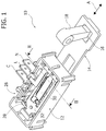
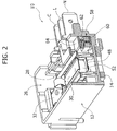
- the door locking device 10 comprises a housing 12 carrying at least two and preferably three fixed electric contacts indicated respectively N, L and C.
- the fixed electric contacts N, L, C include respective metal blades which project from a lateral wall of the housing 12.
- the door locking device 10 comprises a retaining slider 14 which is movable with respect to the housing 12 in a direction indicated by the arrow A.
- the retaining slider 14 has an opening 16 for receiving a hook 18 connected to the door of a domestic appliance, such as a washing machine.
- the retaining slider 14 is movable with respect to the housing 12 in the direction A between a rest position corresponding to the open position of the door and a locking position corresponding to the closed position of the door.
- a helical compression spring 20 is set between the retaining slider 14 and a mounting plate 22.
- the retaining slider 14 is movable in a space defined between a bottom wall 24 of the housing 12 and the mounting plate 22.
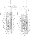
- the spring 20 biases the retaining slider 14 towards its rest position shown in figure 3 .
- the hook 18 connected to the door enters into the opening 16 of the retaining slider 14 and moves the retaining slider 14 in the locking position shown in figure 4 .
- the slider 14 can move from the rest position to the locked position in both directions depending on the model of door lock. In the position of figure 4 the retaining slider 14 locks the hook 18 and prevents opening of the door.
- the door locking device 10 comprises an electric actuator 26 housed into the housing 12.
- the electric actuator 26 comprises a bistable switching device 28 electrically connected to the second electric contact L.
- the bistable switching device 28 is made up of a strip spring 30 and a hoop spring 32.
- the strip spring 30 and hoop spring 32 are preferably made of a single metal strip and have a common end fastened to a metal strip 34 connected to or integral with the second electric terminal L.
- the strip spring 30 and hoop spring 32 are elastically joined by a coupling spring 36.
- the hoop spring 32 of the bistable switching device 28 jumps over from a de-energized stable position shown in figure 3 to an energized stable position shown in figure 4 .
- the bistable switching device 28 includes a locking pin 38 connected to the free end of the hoop spring 32.
- the free end of the locking pin 38 extends through a hole 40 of the bottom wall 24.
- the locking pin 38 is intended to engage a locking hole 42 of the retaining slider 14 when the retaining slider 14 is in the locking position and when the bistable switching device 28 is in the energized stable position (see figure 4 ).
- the hoop spring 32 is provided with a movable contact 44 close to the free end. In the energized position of the bistable switching device 28 the movable contact 44 abuts against a fixed contact 46 carried by the third electric contact C.
- the electric actuator 26 also comprises a bimetal strip 48, a compensating bimetal strip 50 and a PTC resistor 52.
- the PTC resistor 52 is electrically connected between the bimetal strip 48 and the strip spring 30.
- a first end of the bimetal strip 48 is leaned against an adjusting screw 54 and the second end thereof is leaned against the compensating bimetal strip 50.
- Both ends of the compensating bimetal strip 50 are leaned against the bottom wall 54 of the housing 12.
- the adjusting screw 54 is screwed into a threaded hole of an intermediate contact 56 which is leaned against the bottom wall 24.
- the head of the adjusting screw 54 is accessible through a hole of the bottom wall 24.
- the electric actuator 26 might include an electromagnet, or other types of electric actuators, for moving the locking pin 38 between the unlocked position and the locked position.
- the door locking device 10 comprises an integrated door sensing switch 58 electrically connected between the first electric contact N and the electric actuator 26.
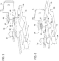
- the door sensing switch 58 includes an helical compression spring 62 made of electrically conducting material and a spring holder 60 preferably made of plastic material.
- the helical compression spring 62 has a first end which abuts against a lateral projection 64 of the first electric contact N.
- the spring holder 60 has a seat 63 for the helical compression spring 62.
- the seat 63 has an open end 65 ( figure 5 ) through which a second end of the helical compression spring 62 is exposed.
- the spring holder 60 is movable between a disconnected circuit position shown in figure 5 and a connected circuit position shown in figure 6 .
- the compression spring 62 elastically biases the spring holder 60 towards the connected circuit position, in which the spring holder 60 abuts against the intermediate contact 56.
- the spring holder 60 has a projection 66 which extends through an aperture of the bottom wall 24 and cooperates with a ramp portion 68 of the retaining slider 14. As best shown in figures 5 and 6 , the ramp portion 68 has a raised portion 70 and a recessed portion 72. When the retaining slider 14 is in the rest position, corresponding to the open condition of the door, the projection 66 abuts against the raised portion 70 of the ramp portion 68 as shown in figures 3 and 5 . In this condition the spring holder 60 is in the disconnected circuit position and, as described above, the electric connection between the first electric contact N and the bimetal strip 48 is interrupted.
- the projection 66 is situated in correspondence with the recessed portion 72 of the ramp 68.
- the spring holder 60 is biased by the spring 62 in the connected circuit position.
- the spring 62 closes the electric connection between the first electric contact N and the bimetal strip 48.
- the bistable switching device 28 When the door sensing switch 58 is in the open condition, electric current cannot flow through the bimetal strip 48 and the PTC resistor 52. Accordingly, the bistable switching device 28 is in the de-energized position shown in figure 3 . In this position the locking pin 38 is raised and the retaining slider 14 is unlocked and free to move in the direction A.
- the door sensing switch 58 moves to the closed position and closes the circuit between the first electric contact N and the bimetal strip 48.
- electric current flows from the first electric contact N to the second electric contact L through the door sensing switch 58, the intermediate contact 56, the adjusting screw 54, the bimetal strip 48, the PTC resistor 52 and the strip spring 30.
- the PTC resistor warms up and the bimetal strip 48, which is in touch with the PTC resistor 52, gets warm too and pushes the PTC resistor 52 towards the strip spring 30.
- the hoop spring 32 jumps over into the energized position shown in figure 4 .
- the locking pin 38 moves to the locking position and engages the locking hole 42 of the retaining slider 14, thereby locking the retaining slider 14 in the locking position.
- the contacts 44, 46 enter into mutual contact and connect electrically the second electric contact L with the third electric contact C, thereby confirming that the door is locked.
Landscapes
- Push-Button Switches (AREA)
Claims (5)
- Türverriegelungsvorrichtung für ein Haushaltsgerät, die Folgendes umfasst:- ein Gehäuse (12), das wenigstens einen ersten und einen zweiten fest angebrachten elektrischen Kontakt (N, L) trägt,- ein Rückhalte-Gleitelement (14), das ein Verriegelungsloch (42) aufweist und in Bezug auf das Gehäuse (12) zwischen einer Ruheposition, die der offenen Position der Tür entspricht, und einer Verriegelungsposition, die der geschlossenen Position der Tür entspricht, bewegt werden kann,- einen elektrischen Aktuator (26), der mit dem zweiten elektrischen Kontakt (L) elektrisch verbunden ist und zwischen einer spannungsfreien Position und einer Position, in der Spannung anliegt, bewegt werden kann, wobei der elektrische Aktuator (26) einen Verriegelungsstift (38) aufweist, der in der Position des elektrischen Aktuators (26), in der Spannung anliegt, mit dem Verriegelungsloch (42) des Rückhalte-Gleitelements (14) in Eingriff gelangt, wenn sich das Rückhalte-Gleitelement (14) in der Verrieglungsposition befindet,dadurch gekennzeichnet, dass sie einen Türerfassungsschalter (58) umfasst, der zwischen dem ersten elektrischen Kontakt (N) und dem elektrischen Aktuator (26) elektrisch angeschlossen ist, wobei der Türerfassungsschalter (58) eine Kompressionsfeder (62) aufweist, deren erstes Ende mit dem ersten elektrischen Kontakt (N) elektrisch verbunden ist und deren zweites Ende, das eine elektrische Verbindung mit einem Zwischenkontakt (56) wahlweise öffnet und schließt, mit dem elektrischen Aktuator (26) elektrisch verbunden ist, wobei das zweite Ende der Kompressionsfeder (62) in einer Aufnahme (63) einer Federhalterung (60) aufgenommen ist, die zwischen einer Position mit unterbrochener Schaltung und einer Position mit geschlossener Schaltung bewegt werden kann, wobei die Federhalterung (60) in Richtung der Position mit geschlossener Schaltung elastisch vorbelastet ist und mit einem Rampenabschnitt (68) des Rückhalte-Gleitelements (14) zusammenwirkt, der die Federhalterung (60) in die Position mit unterbrochener Schaltung drängt, wenn sich das Rückhalte-Gleitelement (14) in der Ruheposition befindet, und der zulässt, dass sich die Federhalterung (60) in die Position mit geschlossener Schaltung bewegt, wenn sich das Rückhalte-Gleitelement (14) in der Verriegelungsposition befindet.
- Türverriegelungsvorrichtung nach Anspruch 1, dadurch gekennzeichnet, dass die Kompressionsfeder (62) zwischen die Federhalterung (60) und einen seitlichen Vorsprung (64) des ersten elektrischen Kontakts (N) eingesetzt ist.
- Türverriegelungsvorrichtung nach Anspruch 1, dadurch gekennzeichnet, dass die Federhalterung (60) einen Vorsprung (66) aufweist, der sich durch ein Loch einer Bodenwand (24) des Gehäuses (12) erstreckt und mit dem Rampenabschnitt (68) zusammenwirkt.
- Türverriegelungsvorrichtung nach Anspruch 1, dadurch gekennzeichnet, dass der Sitz (63) der Federhalterung (60) ein offenes Ende (65) aufweist, durch das das zweite Ende der Kompressionsfeder (62) freiliegt.
- Türverriegelungsvorrichtung nach Anspruch 3, dadurch gekennzeichnet, dass der Rampenabschnitt (68) einen erhöhten Abschnitt (70), der mit dem Vorsprung (66) der Federhalterung (60) übereinstimmt, wenn sich das Rückhalte-Gleitelement (14) in der Ruheposition befindet, und einen ausgesparten Abschnitt (72), der mit dem Vorsprung (66) der Federhalterung (60) übereinstimmt, wenn sich das Rückhalte-Gleitelement (14) in der Verriegelungsposition befindet, aufweist.
Priority Applications (1)
| Application Number | Priority Date | Filing Date | Title |
|---|---|---|---|
| PL13716922T PL2834829T3 (pl) | 2012-04-03 | 2013-04-02 | Urządzenie do blokowania drzwi z wbudowanym przełącznikiem wykrywania drzwi |
Applications Claiming Priority (2)
| Application Number | Priority Date | Filing Date | Title |
|---|---|---|---|
| IT000291A ITTO20120291A1 (it) | 2012-04-03 | 2012-04-03 | Dispositivo di bloccaggio porta con interruttore di rilevamento porta integrato |
| PCT/US2013/034894 WO2013151964A1 (en) | 2012-04-03 | 2013-04-02 | Door locking device with integrated door sensing switch |
Publications (2)
| Publication Number | Publication Date |
|---|---|
| EP2834829A1 EP2834829A1 (de) | 2015-02-11 |
| EP2834829B1 true EP2834829B1 (de) | 2016-03-02 |
Family
ID=46001519
Family Applications (1)
| Application Number | Title | Priority Date | Filing Date |
|---|---|---|---|
| EP13716922.3A Active EP2834829B1 (de) | 2012-04-03 | 2013-04-02 | Türverriegelungsvorrichtung mit integriertem türsensorschalter |
Country Status (4)
| Country | Link |
|---|---|
| EP (1) | EP2834829B1 (de) |
| IT (1) | ITTO20120291A1 (de) |
| PL (1) | PL2834829T3 (de) |
| WO (1) | WO2013151964A1 (de) |
Families Citing this family (4)
| Publication number | Priority date | Publication date | Assignee | Title |
|---|---|---|---|---|
| CN107227586B (zh) * | 2016-03-25 | 2023-11-24 | 伊利诺斯工具制品有限公司 | 电器门锁、电磁门锁组件及电器 |
| IT201700039100A1 (it) * | 2017-04-10 | 2018-10-10 | Bitron Spa | Dispositivo blocca-porta, particolarmente per apparecchi elettrodomestici. |
| EP3916145B1 (de) | 2020-05-25 | 2025-04-16 | ELBI International S.p.A. | Türverriegelungsvorrichtung mit verbessertem sicherheitsmodul |
| EP4624704A1 (de) * | 2024-03-29 | 2025-10-01 | Illinois Tool Works Inc. | Türschloss und elektrisches gerät damit |
Family Cites Families (3)
| Publication number | Priority date | Publication date | Assignee | Title |
|---|---|---|---|---|
| GB9409489D0 (en) * | 1994-05-12 | 1994-06-29 | Diamond H Controls Ltd | Energy regulator |
| SI20537A (sl) | 2000-03-23 | 2001-10-31 | Metalflex | Električni stikalni sklop za varnostno pripravo v stroju |
| SI21888A (sl) * | 2004-10-06 | 2006-04-30 | Itw Metalflex D.O.O. Tolmin | Varnostna zapora vrat gospodinjskih aparatov |
-
2012
- 2012-04-03 IT IT000291A patent/ITTO20120291A1/it unknown
-
2013
- 2013-04-02 EP EP13716922.3A patent/EP2834829B1/de active Active
- 2013-04-02 WO PCT/US2013/034894 patent/WO2013151964A1/en not_active Ceased
- 2013-04-02 PL PL13716922T patent/PL2834829T3/pl unknown
Also Published As
| Publication number | Publication date |
|---|---|
| ITTO20120291A1 (it) | 2013-10-04 |
| EP2834829A1 (de) | 2015-02-11 |
| PL2834829T3 (pl) | 2016-08-31 |
| WO2013151964A1 (en) | 2013-10-10 |
Similar Documents
| Publication | Publication Date | Title |
|---|---|---|
| US8991877B2 (en) | Door lock for the door of a household appliance | |
| WO2013181289A1 (en) | Electromagnetic door-lock | |
| US7549685B2 (en) | Lock for a household appliance | |
| JP6148964B2 (ja) | コネクタ | |
| CN101517182B (zh) | 家用电器的门锁装置 | |
| EP2450510B1 (de) | Türverriegelungsvorrichtung für Haushaltsgerät und bistabiler Mechanismus | |
| US20110133490A1 (en) | Safety lock for a door of a household appliance, preferably of a washing machine | |
| EP2834829B1 (de) | Türverriegelungsvorrichtung mit integriertem türsensorschalter | |
| CN103534778A (zh) | 电开关 | |
| KR102482397B1 (ko) | 특히 가전기기를 위한 도어 잠금 장치 | |
| CN206565918U (zh) | 洗碗机自动门锁系统及洗碗机 | |
| KR102481001B1 (ko) | 특히 가전기기를 위한 도어 잠금 장치 | |
| RU2461906C1 (ru) | Миниатюрный защитный выключатель | |
| EP1726750B1 (de) | Eine Vorrichtung zum Verriegeln einer Bullaugentür einer Waschmaschine | |
| EP1645706B1 (de) | Sicherheitsschloss für eine Tür eines Haushaltsgerätes | |
| KR100793146B1 (ko) | 가전제품의 도어락 안전 차단 방법 및 그 장치 | |
| KR20070118579A (ko) | 전기 회로를 보호하기 위한 보호 회로 스위치 | |
| US9217217B2 (en) | Door-locking device for a household appliance, door arrangement comprising a door-locking device and method for locking a door of a household appliance | |
| US20250003258A1 (en) | Improved door lock for a household appliance | |
| KR970001842Y1 (ko) | 전원 자동 차단형 푸쉬 스위치 | |
| CN118653745A (zh) | 用于家用电器的门锁 | |
| HK1096767B (en) | Electronic function relay | |
| JP2006221894A (ja) | 回路遮断器 | |
| HK1096767A1 (zh) | 电子功能继电器 | |
| KR20080101491A (ko) | 가전제품에 쓰이는 도어 안전 락 장치의 접점유닛 |
Legal Events
| Date | Code | Title | Description |
|---|---|---|---|
| PUAI | Public reference made under article 153(3) epc to a published international application that has entered the european phase |
Free format text: ORIGINAL CODE: 0009012 |
|
| 17P | Request for examination filed |
Effective date: 20140716 |
|
| AK | Designated contracting states |
Kind code of ref document: A1 Designated state(s): AL AT BE BG CH CY CZ DE DK EE ES FI FR GB GR HR HU IE IS IT LI LT LU LV MC MK MT NL NO PL PT RO RS SE SI SK SM TR |
|
| AX | Request for extension of the european patent |
Extension state: BA ME |
|
| DAX | Request for extension of the european patent (deleted) | ||
| GRAP | Despatch of communication of intention to grant a patent |
Free format text: ORIGINAL CODE: EPIDOSNIGR1 |
|
| INTG | Intention to grant announced |
Effective date: 20151015 |
|
| GRAS | Grant fee paid |
Free format text: ORIGINAL CODE: EPIDOSNIGR3 |
|
| GRAA | (expected) grant |
Free format text: ORIGINAL CODE: 0009210 |
|
| AK | Designated contracting states |
Kind code of ref document: B1 Designated state(s): AL AT BE BG CH CY CZ DE DK EE ES FI FR GB GR HR HU IE IS IT LI LT LU LV MC MK MT NL NO PL PT RO RS SE SI SK SM TR |
|
| REG | Reference to a national code |
Ref country code: GB Ref legal event code: FG4D |
|
| REG | Reference to a national code |
Ref country code: AT Ref legal event code: REF Ref document number: 778529 Country of ref document: AT Kind code of ref document: T Effective date: 20160315 Ref country code: CH Ref legal event code: EP |
|
| REG | Reference to a national code |
Ref country code: IE Ref legal event code: FG4D |
|
| REG | Reference to a national code |
Ref country code: DE Ref legal event code: R096 Ref document number: 602013005260 Country of ref document: DE |
|
| REG | Reference to a national code |
Ref country code: NL Ref legal event code: MP Effective date: 20160302 |
|
| REG | Reference to a national code |
Ref country code: LT Ref legal event code: MG4D |
|
| REG | Reference to a national code |
Ref country code: AT Ref legal event code: MK05 Ref document number: 778529 Country of ref document: AT Kind code of ref document: T Effective date: 20160302 |
|
| PG25 | Lapsed in a contracting state [announced via postgrant information from national office to epo] |
Ref country code: NO Free format text: LAPSE BECAUSE OF FAILURE TO SUBMIT A TRANSLATION OF THE DESCRIPTION OR TO PAY THE FEE WITHIN THE PRESCRIBED TIME-LIMIT Effective date: 20160602 Ref country code: GR Free format text: LAPSE BECAUSE OF FAILURE TO SUBMIT A TRANSLATION OF THE DESCRIPTION OR TO PAY THE FEE WITHIN THE PRESCRIBED TIME-LIMIT Effective date: 20160603 Ref country code: FI Free format text: LAPSE BECAUSE OF FAILURE TO SUBMIT A TRANSLATION OF THE DESCRIPTION OR TO PAY THE FEE WITHIN THE PRESCRIBED TIME-LIMIT Effective date: 20160302 Ref country code: HR Free format text: LAPSE BECAUSE OF FAILURE TO SUBMIT A TRANSLATION OF THE DESCRIPTION OR TO PAY THE FEE WITHIN THE PRESCRIBED TIME-LIMIT Effective date: 20160302 Ref country code: ES Free format text: LAPSE BECAUSE OF FAILURE TO SUBMIT A TRANSLATION OF THE DESCRIPTION OR TO PAY THE FEE WITHIN THE PRESCRIBED TIME-LIMIT Effective date: 20160302 |
|
| PG25 | Lapsed in a contracting state [announced via postgrant information from national office to epo] |
Ref country code: SE Free format text: LAPSE BECAUSE OF FAILURE TO SUBMIT A TRANSLATION OF THE DESCRIPTION OR TO PAY THE FEE WITHIN THE PRESCRIBED TIME-LIMIT Effective date: 20160302 Ref country code: BE Free format text: LAPSE BECAUSE OF NON-PAYMENT OF DUE FEES Effective date: 20160430 Ref country code: LV Free format text: LAPSE BECAUSE OF FAILURE TO SUBMIT A TRANSLATION OF THE DESCRIPTION OR TO PAY THE FEE WITHIN THE PRESCRIBED TIME-LIMIT Effective date: 20160302 Ref country code: NL Free format text: LAPSE BECAUSE OF FAILURE TO SUBMIT A TRANSLATION OF THE DESCRIPTION OR TO PAY THE FEE WITHIN THE PRESCRIBED TIME-LIMIT Effective date: 20160302 Ref country code: RS Free format text: LAPSE BECAUSE OF FAILURE TO SUBMIT A TRANSLATION OF THE DESCRIPTION OR TO PAY THE FEE WITHIN THE PRESCRIBED TIME-LIMIT Effective date: 20160302 Ref country code: LT Free format text: LAPSE BECAUSE OF FAILURE TO SUBMIT A TRANSLATION OF THE DESCRIPTION OR TO PAY THE FEE WITHIN THE PRESCRIBED TIME-LIMIT Effective date: 20160302 Ref country code: AT Free format text: LAPSE BECAUSE OF FAILURE TO SUBMIT A TRANSLATION OF THE DESCRIPTION OR TO PAY THE FEE WITHIN THE PRESCRIBED TIME-LIMIT Effective date: 20160302 |
|
| PG25 | Lapsed in a contracting state [announced via postgrant information from national office to epo] |
Ref country code: EE Free format text: LAPSE BECAUSE OF FAILURE TO SUBMIT A TRANSLATION OF THE DESCRIPTION OR TO PAY THE FEE WITHIN THE PRESCRIBED TIME-LIMIT Effective date: 20160302 Ref country code: IS Free format text: LAPSE BECAUSE OF FAILURE TO SUBMIT A TRANSLATION OF THE DESCRIPTION OR TO PAY THE FEE WITHIN THE PRESCRIBED TIME-LIMIT Effective date: 20160702 |
|
| REG | Reference to a national code |
Ref country code: DE Ref legal event code: R119 Ref document number: 602013005260 Country of ref document: DE |
|
| PG25 | Lapsed in a contracting state [announced via postgrant information from national office to epo] |
Ref country code: SK Free format text: LAPSE BECAUSE OF FAILURE TO SUBMIT A TRANSLATION OF THE DESCRIPTION OR TO PAY THE FEE WITHIN THE PRESCRIBED TIME-LIMIT Effective date: 20160302 Ref country code: CZ Free format text: LAPSE BECAUSE OF FAILURE TO SUBMIT A TRANSLATION OF THE DESCRIPTION OR TO PAY THE FEE WITHIN THE PRESCRIBED TIME-LIMIT Effective date: 20160302 Ref country code: SM Free format text: LAPSE BECAUSE OF FAILURE TO SUBMIT A TRANSLATION OF THE DESCRIPTION OR TO PAY THE FEE WITHIN THE PRESCRIBED TIME-LIMIT Effective date: 20160302 Ref country code: RO Free format text: LAPSE BECAUSE OF FAILURE TO SUBMIT A TRANSLATION OF THE DESCRIPTION OR TO PAY THE FEE WITHIN THE PRESCRIBED TIME-LIMIT Effective date: 20160302 Ref country code: PT Free format text: LAPSE BECAUSE OF FAILURE TO SUBMIT A TRANSLATION OF THE DESCRIPTION OR TO PAY THE FEE WITHIN THE PRESCRIBED TIME-LIMIT Effective date: 20160704 |
|
| REG | Reference to a national code |
Ref country code: CH Ref legal event code: PL |
|
| PG25 | Lapsed in a contracting state [announced via postgrant information from national office to epo] |
Ref country code: IT Free format text: LAPSE BECAUSE OF FAILURE TO SUBMIT A TRANSLATION OF THE DESCRIPTION OR TO PAY THE FEE WITHIN THE PRESCRIBED TIME-LIMIT Effective date: 20160302 Ref country code: BE Free format text: LAPSE BECAUSE OF FAILURE TO SUBMIT A TRANSLATION OF THE DESCRIPTION OR TO PAY THE FEE WITHIN THE PRESCRIBED TIME-LIMIT Effective date: 20160302 |
|
| PLBE | No opposition filed within time limit |
Free format text: ORIGINAL CODE: 0009261 |
|
| STAA | Information on the status of an ep patent application or granted ep patent |
Free format text: STATUS: NO OPPOSITION FILED WITHIN TIME LIMIT |
|
| REG | Reference to a national code |
Ref country code: IE Ref legal event code: MM4A |
|
| REG | Reference to a national code |
Ref country code: FR Ref legal event code: ST Effective date: 20161230 |
|
| PG25 | Lapsed in a contracting state [announced via postgrant information from national office to epo] |
Ref country code: DK Free format text: LAPSE BECAUSE OF FAILURE TO SUBMIT A TRANSLATION OF THE DESCRIPTION OR TO PAY THE FEE WITHIN THE PRESCRIBED TIME-LIMIT Effective date: 20160302 Ref country code: FR Free format text: LAPSE BECAUSE OF NON-PAYMENT OF DUE FEES Effective date: 20160502 Ref country code: LI Free format text: LAPSE BECAUSE OF NON-PAYMENT OF DUE FEES Effective date: 20160430 Ref country code: CH Free format text: LAPSE BECAUSE OF NON-PAYMENT OF DUE FEES Effective date: 20160430 Ref country code: DE Free format text: LAPSE BECAUSE OF NON-PAYMENT OF DUE FEES Effective date: 20161101 |
|
| 26N | No opposition filed |
Effective date: 20161205 |
|
| PG25 | Lapsed in a contracting state [announced via postgrant information from national office to epo] |
Ref country code: BG Free format text: LAPSE BECAUSE OF FAILURE TO SUBMIT A TRANSLATION OF THE DESCRIPTION OR TO PAY THE FEE WITHIN THE PRESCRIBED TIME-LIMIT Effective date: 20160602 Ref country code: SI Free format text: LAPSE BECAUSE OF FAILURE TO SUBMIT A TRANSLATION OF THE DESCRIPTION OR TO PAY THE FEE WITHIN THE PRESCRIBED TIME-LIMIT Effective date: 20160302 |
|
| PG25 | Lapsed in a contracting state [announced via postgrant information from national office to epo] |
Ref country code: IE Free format text: LAPSE BECAUSE OF NON-PAYMENT OF DUE FEES Effective date: 20160402 |
|
| GBPC | Gb: european patent ceased through non-payment of renewal fee |
Effective date: 20170402 |
|
| PG25 | Lapsed in a contracting state [announced via postgrant information from national office to epo] |
Ref country code: GB Free format text: LAPSE BECAUSE OF NON-PAYMENT OF DUE FEES Effective date: 20170402 |
|
| PG25 | Lapsed in a contracting state [announced via postgrant information from national office to epo] |
Ref country code: HU Free format text: LAPSE BECAUSE OF FAILURE TO SUBMIT A TRANSLATION OF THE DESCRIPTION OR TO PAY THE FEE WITHIN THE PRESCRIBED TIME-LIMIT; INVALID AB INITIO Effective date: 20130402 |
|
| PG25 | Lapsed in a contracting state [announced via postgrant information from national office to epo] |
Ref country code: MT Free format text: LAPSE BECAUSE OF NON-PAYMENT OF DUE FEES Effective date: 20160430 Ref country code: CY Free format text: LAPSE BECAUSE OF FAILURE TO SUBMIT A TRANSLATION OF THE DESCRIPTION OR TO PAY THE FEE WITHIN THE PRESCRIBED TIME-LIMIT Effective date: 20160302 Ref country code: MK Free format text: LAPSE BECAUSE OF FAILURE TO SUBMIT A TRANSLATION OF THE DESCRIPTION OR TO PAY THE FEE WITHIN THE PRESCRIBED TIME-LIMIT Effective date: 20160302 Ref country code: MC Free format text: LAPSE BECAUSE OF FAILURE TO SUBMIT A TRANSLATION OF THE DESCRIPTION OR TO PAY THE FEE WITHIN THE PRESCRIBED TIME-LIMIT Effective date: 20160302 Ref country code: LU Free format text: LAPSE BECAUSE OF NON-PAYMENT OF DUE FEES Effective date: 20160402 |
|
| PG25 | Lapsed in a contracting state [announced via postgrant information from national office to epo] |
Ref country code: AL Free format text: LAPSE BECAUSE OF FAILURE TO SUBMIT A TRANSLATION OF THE DESCRIPTION OR TO PAY THE FEE WITHIN THE PRESCRIBED TIME-LIMIT Effective date: 20160302 Ref country code: TR Free format text: LAPSE BECAUSE OF FAILURE TO SUBMIT A TRANSLATION OF THE DESCRIPTION OR TO PAY THE FEE WITHIN THE PRESCRIBED TIME-LIMIT Effective date: 20160302 |
|
| P01 | Opt-out of the competence of the unified patent court (upc) registered |
Effective date: 20230606 |
|
| PGFP | Annual fee paid to national office [announced via postgrant information from national office to epo] |
Ref country code: PL Payment date: 20260320 Year of fee payment: 14 |