EP2835105A1 - Système de guidage chirurgical - Google Patents
Système de guidage chirurgical Download PDFInfo
- Publication number
- EP2835105A1 EP2835105A1 EP13179418.2A EP13179418A EP2835105A1 EP 2835105 A1 EP2835105 A1 EP 2835105A1 EP 13179418 A EP13179418 A EP 13179418A EP 2835105 A1 EP2835105 A1 EP 2835105A1
- Authority
- EP
- European Patent Office
- Prior art keywords
- probe
- targeter
- real world
- elements
- orientation
- Prior art date
- Legal status (The legal status is an assumption and is not a legal conclusion. Google has not performed a legal analysis and makes no representation as to the accuracy of the status listed.)
- Withdrawn
Links
- 239000000523 sample Substances 0.000 claims abstract description 232
- 238000005553 drilling Methods 0.000 claims abstract description 44
- 230000000007 visual effect Effects 0.000 claims abstract description 24
- 238000004891 communication Methods 0.000 claims abstract description 4
- 230000033001 locomotion Effects 0.000 claims description 43
- 238000000034 method Methods 0.000 claims description 29
- 238000005259 measurement Methods 0.000 claims description 10
- 230000008859 change Effects 0.000 claims description 4
- 238000003384 imaging method Methods 0.000 claims description 3
- 238000012544 monitoring process Methods 0.000 claims 2
- 238000001356 surgical procedure Methods 0.000 description 27
- 210000000988 bone and bone Anatomy 0.000 description 12
- 239000007943 implant Substances 0.000 description 12
- 210000001519 tissue Anatomy 0.000 description 10
- 230000008685 targeting Effects 0.000 description 6
- 230000007246 mechanism Effects 0.000 description 5
- 210000000845 cartilage Anatomy 0.000 description 4
- 230000008901 benefit Effects 0.000 description 3
- 230000006872 improvement Effects 0.000 description 3
- 210000001503 joint Anatomy 0.000 description 3
- VFWCMGCRMGJXDK-UHFFFAOYSA-N 1-chlorobutane Chemical compound CCCCCl VFWCMGCRMGJXDK-UHFFFAOYSA-N 0.000 description 2
- 230000009545 invasion Effects 0.000 description 2
- 210000003041 ligament Anatomy 0.000 description 2
- ZIBGPFATKBEMQZ-UHFFFAOYSA-N triethylene glycol Chemical compound OCCOCCOCCO ZIBGPFATKBEMQZ-UHFFFAOYSA-N 0.000 description 2
- 238000012800 visualization Methods 0.000 description 2
- 201000009859 Osteochondrosis Diseases 0.000 description 1
- 238000012937 correction Methods 0.000 description 1
- 238000001514 detection method Methods 0.000 description 1
- 208000015181 infectious disease Diseases 0.000 description 1
- 230000003993 interaction Effects 0.000 description 1
- 230000003902 lesion Effects 0.000 description 1
- 230000004048 modification Effects 0.000 description 1
- 238000012986 modification Methods 0.000 description 1
- 208000007656 osteochondritis dissecans Diseases 0.000 description 1
- 230000008569 process Effects 0.000 description 1
- 230000008439 repair process Effects 0.000 description 1
- 210000000323 shoulder joint Anatomy 0.000 description 1
- 238000007794 visualization technique Methods 0.000 description 1
Images


Classifications
-
- A—HUMAN NECESSITIES
- A61—MEDICAL OR VETERINARY SCIENCE; HYGIENE
- A61B—DIAGNOSIS; SURGERY; IDENTIFICATION
- A61B34/00—Computer-aided surgery; Manipulators or robots specially adapted for use in surgery
- A61B34/20—Surgical navigation systems; Devices for tracking or guiding surgical instruments, e.g. for frameless stereotaxis
-
- A—HUMAN NECESSITIES
- A61—MEDICAL OR VETERINARY SCIENCE; HYGIENE
- A61B—DIAGNOSIS; SURGERY; IDENTIFICATION
- A61B17/00—Surgical instruments, devices or methods
- A61B17/16—Instruments for performing osteoclasis; Drills or chisels for bones; Trepans
- A61B17/17—Guides or aligning means for drills, mills, pins or wires
- A61B17/1703—Guides or aligning means for drills, mills, pins or wires using imaging means, e.g. by X-rays
-
- A—HUMAN NECESSITIES
- A61—MEDICAL OR VETERINARY SCIENCE; HYGIENE
- A61B—DIAGNOSIS; SURGERY; IDENTIFICATION
- A61B17/00—Surgical instruments, devices or methods
- A61B17/16—Instruments for performing osteoclasis; Drills or chisels for bones; Trepans
- A61B17/17—Guides or aligning means for drills, mills, pins or wires
- A61B17/1707—Guides or aligning means for drills, mills, pins or wires using electromagnetic effects, e.g. with magnet and external sensors
-
- A—HUMAN NECESSITIES
- A61—MEDICAL OR VETERINARY SCIENCE; HYGIENE
- A61B—DIAGNOSIS; SURGERY; IDENTIFICATION
- A61B17/00—Surgical instruments, devices or methods
- A61B17/16—Instruments for performing osteoclasis; Drills or chisels for bones; Trepans
- A61B17/17—Guides or aligning means for drills, mills, pins or wires
- A61B17/1739—Guides or aligning means for drills, mills, pins or wires specially adapted for particular parts of the body
- A61B17/1778—Guides or aligning means for drills, mills, pins or wires specially adapted for particular parts of the body for the shoulder
-
- A—HUMAN NECESSITIES
- A61—MEDICAL OR VETERINARY SCIENCE; HYGIENE
- A61B—DIAGNOSIS; SURGERY; IDENTIFICATION
- A61B17/00—Surgical instruments, devices or methods
- A61B2017/00681—Aspects not otherwise provided for
- A61B2017/00725—Calibration or performance testing
-
- A—HUMAN NECESSITIES
- A61—MEDICAL OR VETERINARY SCIENCE; HYGIENE
- A61B—DIAGNOSIS; SURGERY; IDENTIFICATION
- A61B17/00—Surgical instruments, devices or methods
- A61B2017/00681—Aspects not otherwise provided for
- A61B2017/00738—Aspects not otherwise provided for part of the tool being offset with respect to a main axis, e.g. for better view for the surgeon
-
- A—HUMAN NECESSITIES
- A61—MEDICAL OR VETERINARY SCIENCE; HYGIENE
- A61B—DIAGNOSIS; SURGERY; IDENTIFICATION
- A61B34/00—Computer-aided surgery; Manipulators or robots specially adapted for use in surgery
- A61B34/10—Computer-aided planning, simulation or modelling of surgical operations
- A61B2034/107—Visualisation of planned trajectories or target regions
-
- A—HUMAN NECESSITIES
- A61—MEDICAL OR VETERINARY SCIENCE; HYGIENE
- A61B—DIAGNOSIS; SURGERY; IDENTIFICATION
- A61B34/00—Computer-aided surgery; Manipulators or robots specially adapted for use in surgery
- A61B34/20—Surgical navigation systems; Devices for tracking or guiding surgical instruments, e.g. for frameless stereotaxis
- A61B2034/2046—Tracking techniques
- A61B2034/2051—Electromagnetic tracking systems
-
- A—HUMAN NECESSITIES
- A61—MEDICAL OR VETERINARY SCIENCE; HYGIENE
- A61B—DIAGNOSIS; SURGERY; IDENTIFICATION
- A61B34/00—Computer-aided surgery; Manipulators or robots specially adapted for use in surgery
- A61B34/20—Surgical navigation systems; Devices for tracking or guiding surgical instruments, e.g. for frameless stereotaxis
- A61B2034/2046—Tracking techniques
- A61B2034/2055—Optical tracking systems
-
- A—HUMAN NECESSITIES
- A61—MEDICAL OR VETERINARY SCIENCE; HYGIENE
- A61B—DIAGNOSIS; SURGERY; IDENTIFICATION
- A61B34/00—Computer-aided surgery; Manipulators or robots specially adapted for use in surgery
- A61B34/20—Surgical navigation systems; Devices for tracking or guiding surgical instruments, e.g. for frameless stereotaxis
- A61B2034/2068—Surgical navigation systems; Devices for tracking or guiding surgical instruments, e.g. for frameless stereotaxis using pointers, e.g. pointers having reference marks for determining coordinates of body points
-
- A—HUMAN NECESSITIES
- A61—MEDICAL OR VETERINARY SCIENCE; HYGIENE
- A61B—DIAGNOSIS; SURGERY; IDENTIFICATION
- A61B34/00—Computer-aided surgery; Manipulators or robots specially adapted for use in surgery
- A61B34/20—Surgical navigation systems; Devices for tracking or guiding surgical instruments, e.g. for frameless stereotaxis
- A61B2034/2072—Reference field transducer attached to an instrument or patient
-
- A—HUMAN NECESSITIES
- A61—MEDICAL OR VETERINARY SCIENCE; HYGIENE
- A61B—DIAGNOSIS; SURGERY; IDENTIFICATION
- A61B34/00—Computer-aided surgery; Manipulators or robots specially adapted for use in surgery
- A61B34/20—Surgical navigation systems; Devices for tracking or guiding surgical instruments, e.g. for frameless stereotaxis
- A61B2034/2074—Interface software
-
- A—HUMAN NECESSITIES
- A61—MEDICAL OR VETERINARY SCIENCE; HYGIENE
- A61B—DIAGNOSIS; SURGERY; IDENTIFICATION
- A61B34/00—Computer-aided surgery; Manipulators or robots specially adapted for use in surgery
- A61B34/25—User interfaces for surgical systems
- A61B2034/252—User interfaces for surgical systems indicating steps of a surgical procedure
-
- A—HUMAN NECESSITIES
- A61—MEDICAL OR VETERINARY SCIENCE; HYGIENE
- A61B—DIAGNOSIS; SURGERY; IDENTIFICATION
- A61B90/00—Instruments, implements or accessories specially adapted for surgery or diagnosis and not covered by any of the groups A61B1/00 - A61B50/00, e.g. for luxation treatment or for protecting wound edges
- A61B90/36—Image-producing devices or illumination devices not otherwise provided for
- A61B2090/363—Use of fiducial points
-
- A—HUMAN NECESSITIES
- A61—MEDICAL OR VETERINARY SCIENCE; HYGIENE
- A61B—DIAGNOSIS; SURGERY; IDENTIFICATION
- A61B90/00—Instruments, implements or accessories specially adapted for surgery or diagnosis and not covered by any of the groups A61B1/00 - A61B50/00, e.g. for luxation treatment or for protecting wound edges
- A61B90/36—Image-producing devices or illumination devices not otherwise provided for
- A61B2090/364—Correlation of different images or relation of image positions in respect to the body
- A61B2090/368—Correlation of different images or relation of image positions in respect to the body changing the image on a display according to the operator's position
-
- A—HUMAN NECESSITIES
- A61—MEDICAL OR VETERINARY SCIENCE; HYGIENE
- A61B—DIAGNOSIS; SURGERY; IDENTIFICATION
- A61B90/00—Instruments, implements or accessories specially adapted for surgery or diagnosis and not covered by any of the groups A61B1/00 - A61B50/00, e.g. for luxation treatment or for protecting wound edges
- A61B90/36—Image-producing devices or illumination devices not otherwise provided for
- A61B90/37—Surgical systems with images on a monitor during operation
- A61B2090/376—Surgical systems with images on a monitor during operation using X-rays, e.g. fluoroscopy
-
- A—HUMAN NECESSITIES
- A61—MEDICAL OR VETERINARY SCIENCE; HYGIENE
- A61B—DIAGNOSIS; SURGERY; IDENTIFICATION
- A61B90/00—Instruments, implements or accessories specially adapted for surgery or diagnosis and not covered by any of the groups A61B1/00 - A61B50/00, e.g. for luxation treatment or for protecting wound edges
- A61B90/39—Markers, e.g. radio-opaque or breast lesions markers
- A61B2090/3937—Visible markers
-
- A—HUMAN NECESSITIES
- A61—MEDICAL OR VETERINARY SCIENCE; HYGIENE
- A61B—DIAGNOSIS; SURGERY; IDENTIFICATION
- A61B90/00—Instruments, implements or accessories specially adapted for surgery or diagnosis and not covered by any of the groups A61B1/00 - A61B50/00, e.g. for luxation treatment or for protecting wound edges
- A61B90/39—Markers, e.g. radio-opaque or breast lesions markers
- A61B2090/3954—Markers, e.g. radio-opaque or breast lesions markers magnetic, e.g. NMR or MRI
-
- A—HUMAN NECESSITIES
- A61—MEDICAL OR VETERINARY SCIENCE; HYGIENE
- A61B—DIAGNOSIS; SURGERY; IDENTIFICATION
- A61B90/00—Instruments, implements or accessories specially adapted for surgery or diagnosis and not covered by any of the groups A61B1/00 - A61B50/00, e.g. for luxation treatment or for protecting wound edges
- A61B90/39—Markers, e.g. radio-opaque or breast lesions markers
- A61B2090/3966—Radiopaque markers visible in an X-ray image
-
- A—HUMAN NECESSITIES
- A61—MEDICAL OR VETERINARY SCIENCE; HYGIENE
- A61B—DIAGNOSIS; SURGERY; IDENTIFICATION
- A61B90/00—Instruments, implements or accessories specially adapted for surgery or diagnosis and not covered by any of the groups A61B1/00 - A61B50/00, e.g. for luxation treatment or for protecting wound edges
- A61B90/39—Markers, e.g. radio-opaque or breast lesions markers
- A61B2090/3983—Reference marker arrangements for use with image guided surgery
Definitions
- New surgical techniques are being constantly developed and improved, and in a number of situations these surgical techniques relate to correction of damage to ligaments or other aspects relating to joints and the like.
- these surgical techniques relate to correction of damage to ligaments or other aspects relating to joints and the like.
- damage to occur in joints and ligaments of the body which need surgical techniques to properly repair and restore the normal freedom of movement to the body.
- Many of these techniques are desirably undertaken by means of orthoscopic techniques; generally these techniques meaning that the surgical site is not fully open or investigated during the surgical procedure, rather the surgeon uses a small camera within the cavity or joint of the patient in order to visualise what is occurring.
- Many surgical techniques for example those of transcoracoid-transclavicular drilling, preferably require the surgeon to make a bore or drill hole through a portion of the patient's body to a desired site, wherein the end of the bore hole is defined within the patient's body but not visible to the surgeon when drilling.
- a surgeon is required to drill through the bone of the patient into the centre of a joint, for example to the underside of the joint cartilage, it is desirable for the patient's joint to be generally undisturbed and for the drill bore to proceed to the desired point within the joints - without the surgeon viewing the end point of the bore from the other side. That is, in many situations the surgical procedure is much improved by leaving the cartilage in an undisturbed, or minimally disturbed, state, thus meaning that the surgeon uses their skill in locating the bore and stopping the drill at the desired end point within the joint.
- Know surgical guidance systems exist, for example the Smith & Nephew Trigen Sure-Shot System, wherein these systems provide a targeter which can locate a chip present or inluded in an implant within the patient.
- Certain surgical procedures require the introduction of an intramedullary nail into the bone of a patient., wherein this nail is to be fixed by means of screws and bolts.
- the Smith & Nephew System introduces a chip which can be sensed by the targeting system so as to locate the bore in the intramedullary nail to allow for successful drilling by the surgeon. Location of the chip positioned within the implant in the patient's body thus allows the surgeon to make a proper drill hole into the bone of the patient and successfully find the fixation bore of the implant.
- This known technique provides a mechanism of reliably locating a bore within an implant placed in the body of a patient. Such a technique does improve the accuracy of a surgeon drilling into a patient, however this requires that the patient has undergone serious surgery in order to introduce an implant within the bone. This system is not intended for use in simply drilling into the bone of a patient, and explicitly requires the use of both the implant with a chip and the targeter.
- the present disclosure relates to a guidance system which can be used by a surgeon in situations where a patient has not already undergone surgery to have an implant placed within the body.
- this system allows for accurate guidance of a drill bit and drill bore without the necessity of implanting a targeting chip or beacon within the body of the patient in order to guide the surgeon.
- the guidance system is best seen in the discussion of independent claim 1, wherein a method of properly calibrating this system is defined in independent claim 13.
- the present disclosure relates to a guidance system for surgery and in particular one for improvement of drilling in an orthoscopic surgical technique.
- the system comprises a probe, wherein the probe is preferably utilised for highlighting the end point within the patient's body to which the drill bore should extend.
- the probe is preferably structured such that the end point of the probe can be positioned within a patient's body.
- the system advantageously comprises a targeter or target module, wherein the targeter is configured to be able to sense the end of the probe, and thus the end point of a drill line.
- the system further incorporates some form of drill guide or drill tube for providing a guidance to a drill bit when drilling into the patient's body, such that measurements made by the targeter can be used to align the drill guide to the desired end point of the bore to be drilled.
- a control system may be provided which is to be used in conjunction with the targeter providing a real time visualisation of the end of the probe and the targeter.
- the control system may be provided to highlight the direction in which drilling would proceed through the targeter, and the end of the probe to ensure that drilling can proceed in a successful manner.
- the probe may preferably comprise an elongate shaft, such that the probe can be inserted into a patient's body. Along this shaft one or more elements which can be sensed by the targeter can be positioned, such that the targeter and control system may determine the location of the probe, and in particular the end of the probe to allow for the system to properly guide the drill. These elements are specifically, and preferably, located away from the probe's end.
- the control system is preferably adapted such that it may make measurements or take measurements from the targeter or targeting module, and from these measurements make a determination of the end of the probe and thus the desired point for the end of the drill bore. Not only with this system sense the direction along the drilling line through the drill guide, but will also sense the distance from the drill guide to the end of the probe to allow for the correct bore to be made.
- the system may also comprise some means of generating an image for the surgeon such that the end of the probe, the direction and the end of the drill guide can be readably seen and grasped.
- This means that the drill guide can be properly aligned to provide a desired drilling direction to the end of the probe, and the angle of the drill guide can also be shown on the screen to the user to also allow for the surgeon to select a desired angle in which to drill, which is often very important in certain surgical procedures.
- the entire system is devised in such a manner that the visual representation of the targeter, and in particular the direction of the drill guide, and the end of the probe correlates with the real world directions of the drill guide and probe.
- the surgeon is using the system wherein the onscreen or other visual representation of the system matches with the real world directions, movement of the targeter to the left will also mean that the image changes to move the visual representation of the targeter with respect to the probe to the left. It will be understood that this greatly improves the intuitive nature of the system, and leads to great improvement in the accuracy and speed of use of the system in locating the correct position of the drill guide with respect to the probe.
- the system can properly correlate the drill guide angle with the end of the probe and show this relationship on the visual representation.
- a calibration routine or subsection of the control system may be provided, such that the surgeon can properly calibrate the real world orientation of the probe and store this in the system.
- the surgeon is not restricted in the actual direction in which the probe is positioned into the patient, and greater flexibility of the technique is given.
- control system is preferably adapted to recognise a triggering act or signal.
- the actual act or signal is not in any way limited, however it is preferable that this act or signal is unlikely to arise during actual surgical procedure, so as to avoid an inadvertent calibration routine rather than proper targeting of the system.
- the end of the targeter brought into close proximity with the end of the probe; for the surgeon to provide a certain predetermined set of motions of the targeter near the probe; to actuate a switch or other element on the probe or targeter; to move the targeter in such a manner that the probe cannot be sensed by the targeter, wherein preferably this could be done for a predetermined length of time.
- control system can monitor any relative motion between the probe and the targeter and determine this to be a change in the real world orientation of the probe - rather than an actual target procedure.
- the surgeon does not need to keep the orientation of the probe generally the same after calibration, and further the intuitive nature of the system and accuracy of the surgery will be improved.
- a preferable structure to the probe is to comprise elements which can be seen by the targeter at a position on the probe which is not going to be positioned within the patient's body during targeting.
- these elements could be any one or more of coils, magnets, RFIDs, denser portions of the shaft, other electromagnetically discernible elements. It is also preferable that if multiple elements are provided, each of these elements is different. The difference is in no way limited, however by providing a difference which can be sensed by the targeter, the end of the probe can be determined by means of the two elements in a quicker and more accurate manner. To this end, it is preferable if the targeter is in some way an electromagnetic sensor such that the elements can be readily viewed.
- a further modification in the system could be to combine the drill guide or drill tube with the targeter, so that the targeter and drill guide form a combined unit.
- This has the advantage that the targeter can be used to locate the end of the probe and then can at the same time properly align the drill guide for performing the desired surgery.
- a method for calibration of the above system can also be provided.
- the method of use of the above targeter, probe and control system could allow for some triggering step to reset any predefined orientation of the probe in the system.
- the control system can provide instructions to the user via the real time visual representation, so as to instruct the user how to move one or other of the probe or targeter with respect to the other of the targeter or probe.
- the system may then monitor the relative motion between the probe and the targeter, and use this to determine the actual real world orientation of the probe in use.
- Such a method allows for the surgeon to properly program the system to understand the real world direction of the probe, and thus improve the visual representation and visual movement in correlation with the real world movement.
- this method be provided with a continued learning phase, wherein after the calibration has occurred the system monitors all movement of the probe with relation to the targeter and uses this to update the real world orientation of the probe. In such a manner, the accuracy of the visual representation can be improved even further thus ensuring that surgery can proceed in a swift an accurate manner.
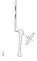
- a surgical guidance system 1 which comprises a probe 10 and targeter 20.
- Fig. 1 shows a general representation of the probe 10 and targeter 20.
- certain surgical techniques and procedures for example Transcoracoid-Transclavicular Drilling or Retrograde Drilling of Osteochondritis Dissecans Lesions, wherein it is preferable to drill through a portion of body tissue to a desired site within the body of a patient from a side where the desired end of the drill site cannot be seen.
- the targeter 20 may be used to locate the end of the probe 12.
- the surgeon will initially place the probe 10 such that the end of the probe 12 is located at the desired end point of the hole to be drilled.
- the positioning of the probe 10 at such a position, and in particular the end of the probe 12, is less invasive than drilling to this position, or otherwise, and the surgeon can thus ensure that minimal damage to surrounding body tissue ensues from the probe 10 placement.
- the targeter 20 can be used to locate the end of the probe 12, and thus aid the surgeon in drilling to the desired end point and site within the body.
- the targeter 20 is preferably provided with a drilling guide 21, wherein the drilling guide 21 can take any form appropriate for ensuring that a drill will proceed in the direction of the drilling guide 21.
- the drilling guide 21 can take any form appropriate for ensuring that a drill will proceed in the direction of the drilling guide 21.
- One example would simply be a hole through the targeter 20, or even a hole through the targeter 20 and an extended elongated tube through which a bore passes, to ensure that the drill proceeds in the correct angle.
- the targeter 20 and drill guide 21 define a drill line 22, wherein the drill line 22 is the line along which the drill will progress and the bore in the body tissue will be made.
- the targeter 20 locates the end of the probe 12
- the system 1 it is also possible by using the system 1 to ensure that the drilled hole does not extend too far.
- the end of the probe 12 provides a definite point within the body of the patient, and the targeter 20 can not only guide the angle of the drill line into the direction of the probe 12, but will also be able to determine how far the end of the probe 12 is from the end of the drill guide 23. This ensures that the bore which is drilled in the bone, or other body tissue, will not extend too far and will end exactly at the head of the probe 12.
- the system allows for great flexibility and accuracy in locating a drill hole through body tissue to an end and desired point - without the need for invasive opening of the joint or other visualisation techniques, as have been discussed in the prior art as being undesirable. Figs.
- FIGS. 2 and 3 also show the surgical guidance system 1 in use, wherein the probe 10 can be positioned on one side of a bone, and the targeter 20 can be used to align the drill line 22 such that the drilling will proceed in the appropriate direction and will arrive at the end of the probe 12.
- the present system 1 preferably incorporates one or more elements 11 on the probe 10 which can be visualised by the targeter 20.
- the targeter 20 is an electromagnetic targeter, and thus requires only that the position of the one or more elements 11 can be determined by electromagnetic means.
- the prior art system discussed above to Smith & Nephew, that of the Trigen Sure-Shot System provides an electromagnetic sensor as the targeter 20, and can be used to target a chip which has been placed into an intramedullary nail.
- the present system utilises the same concepts as defined in this prior known system, however instead of positioning the chip into an implant, the present system provides the reusable and user positionable probe 10.
- the known technique uses a targeter 20 as described above to locate a chip which is positioned within an implant which has already been placed within a patient.
- the prior art therefore, does not allow for the user of the system to pick a desired location in the body as the end point of a drilling line, as it provides an element within an implant which can be sensed by means of an electromagnetic targeter.
- space requirements for locating an item which can be sensed electromagnetically are of little concern, as the skilled person will realise that positioning an implant within the body of a patient is already a rather invasive technique, and most implants are of a sufficient size to allow for a chip, or other item which can be sensed by the electromagnetic targeter 20, to be positioned therein.
- the present case requires that the minimum invasion of the patient's body be made in order to position the end of the probe 12 at the desired end site of the drilling hole.
- the surgeon would usually use an orthoscopic technique to view the joint or other body part to which a hole must be drilled, and further would require or desire to use a small probe 10 for positioning the end of the probe 12 at the desired end site of the hole.
- the end of the probe 12 - and indeed most of the probe 10 itself should desirably be of as small a size as possible, thus ensuring that the minimum disruption to the patient's body at the side not being drilled is made. In some surgical techniques it is preferred not to interfere with the other side of the drill line as much as possible, and thus the use of large or bulky probes 10 to locate the end of the drilled hole is undesirable.
- the probe 10 may be provided with one or more elements 11 at a position away from the end of the probe 12.
- the end of the probe can be made into a very small and readily positionable point, such that minimum invasion and damage to surrounding tissue occurs.
- the targeter 20 by providing a very small end to the probe 12 to avoid damage, it is not possible for the targeter 20 to focus and obtain accurate readings of the end 12, as it is also very difficult to put a sufficiently detectable element 11 at the end of the very small probe 12.
- the newly described system 1 proposes the use of one or more elements 11 away from the distal end of the probe 12.
- the elements 11 By positioning the elements 11 along the shaft of the probe 13, it is possible to both make the end of the probe 12 a very small point, and also ensure that the targeter 20 can properly visualise the elements 11 and take an appropriate reading therefrom.
- two elements 11 are positioned along the shaft 13 of the probe 10, and that these elements 11 are positioned away from the end of the probe 12.
- the two elements 11 are positioned a sufficient distance away from the end of the probe 12 such that the two elements 11 are not placed within the body of the patient when the probe 10 is located with the end of the probe 12 at the desired drilling point.
- the probe 10 may be provided with a hook 14 as the end of the probe 12, wherein the hook 14 can be used in order to also define both the end of the probe 12 and in some cases also a further extension of the drilling line 22.
- the positioning of a hook 14 at the end of the probe 10 is not problematic, as the system 1 can also determine the offset from the elements 11 of the end of the probe 12.
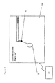
- a control system 30 shown schematically in some form of communication with the targeter 20 or the like in the figures, which is in communication with the targeter 20.
- the targeter 20 will take measurements and will locate the positions of the one or more elements 11, and can thus then provide this information to the control system 30.
- the control system 30 then takes the information as to the position of the elements 11, and can calculate the location of the end of the probe 12.
- the control system 30 is obviously precalibrated to determine the precise location of the end of the probe 12 from the measurement of the position of the one or more elements 11, even when the probe 10 is provided with a hook 14. To this end, the measurements taken by the targeter 20 are transferred to the control system 30 this can calculate the relative position of the end of the probe 12 with regard to the end of the drill guide 23.
- the control system 30 so designed to calculate the relative positions of the end of the probe 12 and the end of the drill guide 23, but it can also take account of the extension of the drill line 22 with respect to the head of the probe 12.
- the targeter 20 will need to be moved in order to align the drill guide 21 appropriately.
- the control system remains in contact with the targeter 20 and thus obtains real time information of the relative locations of the head of the probe 12, the end of the drill guide 23 and the drill line 22.
- the surgeon can obviously move the targeter 20 until the drill line 22 overlaps with the end of the probe 12.
- control system 30 can indicate the distance between the end of the drill guide 23 and the end of the probe 12, along the drill line 22, such that the surgeon knows exactly how far to drill into the patient to reach the end of the probe 12.
- system is also adapted to be able to highlight the relative angle between the drill line 22 and the end of the probe 12, and show this on the image. This would allow certain procedures to also ensure that the drill line 22 will not only overlap with the end of the probe 12, but will also be at a specific angle - which can be advantageous in certain surgical procedures.
- the system will thus provide a real time image indicating both the end of the probe 12 as well as the location of the end of the drill guide 23 and the direction of the drill line 22; this will allow the surgeon to move the targeter 20 and align the drill line 22 with the end of the probe 12.
- a system is schematically shown in Fig. 4 , wherein the end of the probe 12 is highlighted by the dot 32, the circle 33 represents a physical location of the end of the drill guide 23 in relation to the end of the probe 12, and the line represents the drill line 22.
- the guidance system 1 would be greatly improved in usability when the visual representation of the end of the drill guide 23 as well as the drill line 22 and the end of the probe 12 aligns with the "real world" orientation of the probe 10 and targeter 20.
- the term "real world” will always be used to indicate the physical orientations and positions of all elements of the guidance system 1 in and around the user of the system and patient.
- the real world orientations are those which the user of the system perceives and in essence lives in, as opposed to the graphical representation 31 on the display device of the guidance system 1.
- the location of the end of the probe 12 can be determined from sensing of the one or more elements 11.
- the directional line of the probe 10 can be understood by the control system 30, and the location of the end of the probe 12 can be derived therefrom.
- a possible way of determining the actual direction of the probe 10 is to provide the elements 11 with a different nature which can be sensed by the control system 30. For example, if each of the multiple elements 11 were to be different - for example a coil which can be sensed by the EM sensor of the targeter 20, or an RFID tag, or a denser portion of the shaft 13, or the like - it is possible for the actual direction of the probe 10 with respect to the targeter 20 to be determined.
- the control system 30 knows the direction of the probe 10, and in particular the direction of the shaft 13, the position of the end of the probe 12 can be located with respect to the targeter 20. In particular, the position of the end of the probe 12 can be determined with respect to the end of the drill guide 23 and the drill line 22.
- a simple technique would be to always ensure that the probe 10 extends in a known direction to the control system 30, such that once the location of the one or more elements 11, and thus the end of the probe 12, have been determined, the movement of the targeter 20 is also properly aligned with the image on the screen.
- the present guidance system 1 proposes some form of calibration to ensure that the real world directions of the probe 10 and targeter 20 are aligned with the visualisation directions as determined by the control system 30.
- the user can thus calibrate the known position of the probe 10 with the targeter 20, and ensure that the control system 30 has a clear understanding of the actual physical orientation in the real world of the probe 10 and can thus ensure that relative movements of the targeter 20 will then be shown accurately on the visual representation 31.
- the user could begin the calibration routine by means of some triggering signal.
- the control system 30 can then guide the user of the system through a series of motions of either the probe 10 or targeter 20, to ensure that the location of the probe 10 in the real world can be monitored by the control system 30 such that later relative movements between the targeter 20 and the probe 10 can be co-ordinated between the real world and the visual representation 31. It is generally easier to provide the probe 10 in a fixed orientation and move the targeter 20 with respect thereto, however the skilled person will realise that the exact opposite will also allow the system 30 to determine the orientation of the probe 10.
- triggering signal is not really limited to any single technique. It is desirable on the part of the user to avoid having to interact with anything other than the probe 10 and targeter 20, and thus a preferred technique is generally one which requires the user not to have to interact with the control system 30 directly or physically.
- a preferred technique is generally one which requires the user not to have to interact with the control system 30 directly or physically.
- the end of the drill guide 23 could be brought into contact or very near contact with the end of the probe 12, this can be registered by the control system 30 as a triggering signal which will then lead the control system 30 to begin a calibration routine.
- a known motion of the targeter 20 could be used in relation to the probe 10 in order to begin the calibration routine.
- the triggering signal could be the physical removal of the targeter 20 away from the probe 10, such that the field of view of the targeter 20 no longer comprises the probe 10 at all, and maintaining the targeter 20 away from the probe 10 for a sufficiently long time to ensure resetting of the system.
- any form of motion between the probe and targeter 20 can be used to start the calibration routine, and thus the system is not really limited to any of the possibilities.
- the simplest mechanism of determining the real world orientation of the probe 10 by the control system 30, is to lead the user of the system through a series of defined motions of the targeter 20 in the real world. For example, moving the targeter 20 to the left; followed by to the right; followed by up; followed by down, will lead the control system 30 to fully understand the physical orientation of the probe 10 in the real world, and thus the probe 10 orientation can be stored and the visual representation 31 between the motion of the targeter 20 with respect to the probe 10 can be coordinated for easy use by the surgeon. Other motions of the targeter 20 can also be used to indicate the location of the probe 10, and in fact the probe 10 can be moved instead of moving the targeter 20.
- the actual mechanism by which the control system 30 determines the orientation of the probe 10 is, as stressed a second time, not limited, and it is the provision of the calibration routine in order for the control system 30 to learn the real world orientation of the probe 10 that is important.
- the orientation of the probe 10 in the real world should probably not change too much from that of the targeter 20.
- a preferable further step to the calibration method is to allow for the system to monitor the movement of the probe 10 and update the stored probe 10 orientation.
- the targeter 20 could be maintained in its known orientation and monitor the motion of the probe 10 as this is placed into the desired surgical site.
- the control system 30 could stop updating the orientation of the probe 10 and then allow for the relative movement between the end of the probe 12 and the targeter 20 to be understood as motion of the targeter 20 to align the drill line 22 to the end of the probe 12. That is, after a certain amount of learning time, the control system 30 assumes that the probe 10 is in location such that the end of the probe 12 now marks the desired end point of the drill, such that the motion of the targeter 20 is then treated as a targeting motion, rather than a calibration motion. In this manner, even motion of the probe 10 after calibration will be updated as the orientation of the probe in the system, further increasing the accuracy of the system 1.
- a further advantage of the second probe 10 orientation storage is that should the surgeon need to dramatically change the orientation of the probe 10 in the real world as a result of trying to get to the site at the end of the drill hole, it will not be necessary to go through the calibration routine a second time. Again this improves the interaction of the surgeon with the display and greatly improves the accuracy of using the guidance system 1. Furthermore, the speed of using the system 1 is increased which again reduces the length of a surgical procedure which is always desirable.
- the system is shown with a combined targeter 20 and drill guide 21, however this is for convenience only - at all points the skilled person will appreciate that the targeter 20 could be separate from the drill guide 21. Indeed, in some surgical techniques it is actually preferable for the drill guide 21 to be a separate item and not part of the targeter 20. In such cases the surgeon could locate the separate drill guide 21 in the desired orientation and position - based on the measurements made by the targeter 20 for locating the end of the probe 12. An assistant could hold the targeter 20 behind the separate drill guide 21 along the same line as the drill line 22 of the drill guide 21, so as to allow alignment of the drill guide 21 with the end of the probe 12.
Landscapes
- Health & Medical Sciences (AREA)
- Life Sciences & Earth Sciences (AREA)
- Surgery (AREA)
- Engineering & Computer Science (AREA)
- Nuclear Medicine, Radiotherapy & Molecular Imaging (AREA)
- Animal Behavior & Ethology (AREA)
- Heart & Thoracic Surgery (AREA)
- Medical Informatics (AREA)
- Molecular Biology (AREA)
- Biomedical Technology (AREA)
- General Health & Medical Sciences (AREA)
- Public Health (AREA)
- Veterinary Medicine (AREA)
- Dentistry (AREA)
- Orthopedic Medicine & Surgery (AREA)
- Oral & Maxillofacial Surgery (AREA)
- Robotics (AREA)
- Radiology & Medical Imaging (AREA)
- Pathology (AREA)
- Physics & Mathematics (AREA)
- Electromagnetism (AREA)
- Surgical Instruments (AREA)
Priority Applications (4)
| Application Number | Priority Date | Filing Date | Title |
|---|---|---|---|
| EP13179418.2A EP2835105A1 (fr) | 2013-08-06 | 2013-08-06 | Système de guidage chirurgical |
| PCT/EP2014/066946 WO2015018877A1 (fr) | 2013-08-06 | 2014-08-06 | Système de guidage chirurgical pour un forage orthoscopique |
| EP14747686.5A EP3030189A1 (fr) | 2013-08-06 | 2014-08-06 | Système de guidage chirurgical pour un forage orthoscopique |
| US15/016,922 US20160151119A1 (en) | 2013-08-06 | 2016-02-05 | Surgical guidance system |
Applications Claiming Priority (1)
| Application Number | Priority Date | Filing Date | Title |
|---|---|---|---|
| EP13179418.2A EP2835105A1 (fr) | 2013-08-06 | 2013-08-06 | Système de guidage chirurgical |
Publications (1)
| Publication Number | Publication Date |
|---|---|
| EP2835105A1 true EP2835105A1 (fr) | 2015-02-11 |
Family
ID=48918276
Family Applications (2)
| Application Number | Title | Priority Date | Filing Date |
|---|---|---|---|
| EP13179418.2A Withdrawn EP2835105A1 (fr) | 2013-08-06 | 2013-08-06 | Système de guidage chirurgical |
| EP14747686.5A Withdrawn EP3030189A1 (fr) | 2013-08-06 | 2014-08-06 | Système de guidage chirurgical pour un forage orthoscopique |
Family Applications After (1)
| Application Number | Title | Priority Date | Filing Date |
|---|---|---|---|
| EP14747686.5A Withdrawn EP3030189A1 (fr) | 2013-08-06 | 2014-08-06 | Système de guidage chirurgical pour un forage orthoscopique |
Country Status (3)
| Country | Link |
|---|---|
| US (1) | US20160151119A1 (fr) |
| EP (2) | EP2835105A1 (fr) |
| WO (1) | WO2015018877A1 (fr) |
Cited By (1)
| Publication number | Priority date | Publication date | Assignee | Title |
|---|---|---|---|---|
| WO2017008119A1 (fr) | 2015-07-15 | 2017-01-19 | 360 Knee Systems Pty Ltd | Configuration d'outil chirurgical |
Families Citing this family (19)
| Publication number | Priority date | Publication date | Assignee | Title |
|---|---|---|---|---|
| US8388624B2 (en) | 2003-02-24 | 2013-03-05 | Arthrosurface Incorporated | Trochlear resurfacing system and method |
| EP1765201A4 (fr) | 2004-06-28 | 2013-01-23 | Arthrosurface Inc | Systeme de remplacement de surface articulaire |
| AU2007332787A1 (en) | 2006-12-11 | 2008-06-19 | Arthrosurface Incorporated | Retrograde resection apparatus and method |
| WO2016154393A1 (fr) | 2009-04-17 | 2016-09-29 | Arthrosurface Incorporated | Système de réparation de glénoïde et ses méthodes d'utilisation |
| WO2010121250A1 (fr) | 2009-04-17 | 2010-10-21 | Arthrosurface Incorporated | Système et procédé de re-surfaçage de glénoïde |
| AU2011222404A1 (en) | 2010-03-05 | 2012-09-27 | Arthrosurface Incorporated | Tibial resurfacing system and method |
| EP2804565B1 (fr) | 2011-12-22 | 2018-03-07 | Arthrosurface Incorporated | Système pour une fixation osseuse |
| DE112013003358T5 (de) | 2012-07-03 | 2015-03-19 | Arthrosurface, Inc. | System und Verfahren für Gelenkoberflächenersatz und -reparatur |
| US9492200B2 (en) | 2013-04-16 | 2016-11-15 | Arthrosurface Incorporated | Suture system and method |
| US11607319B2 (en) | 2014-03-07 | 2023-03-21 | Arthrosurface Incorporated | System and method for repairing articular surfaces |
| US20150250472A1 (en) | 2014-03-07 | 2015-09-10 | Arthrosurface Incorporated | Delivery System for Articular Surface Implant |
| US10624748B2 (en) | 2014-03-07 | 2020-04-21 | Arthrosurface Incorporated | System and method for repairing articular surfaces |
| US11160663B2 (en) | 2017-08-04 | 2021-11-02 | Arthrosurface Incorporated | Multicomponent articular surface implant |
| US11617493B2 (en) | 2018-12-13 | 2023-04-04 | Covidien Lp | Thoracic imaging, distance measuring, surgical awareness, and notification system and method |
| US11801113B2 (en) | 2018-12-13 | 2023-10-31 | Covidien Lp | Thoracic imaging, distance measuring, and notification system and method |
| US11478358B2 (en) | 2019-03-12 | 2022-10-25 | Arthrosurface Incorporated | Humeral and glenoid articular surface implant systems and methods |
| US11690680B2 (en) | 2019-03-19 | 2023-07-04 | Mako Surgical Corp. | Trackable protective packaging for tools and methods for calibrating tool installation using the same |
| JP7609443B2 (ja) * | 2019-12-30 | 2025-01-07 | 公立大学法人公立諏訪東京理科大学 | 穿孔装置 |
| USD1121826S1 (en) | 2023-08-18 | 2026-04-07 | Stryker European Operations Limited | Surgical tracker |
Citations (2)
| Publication number | Priority date | Publication date | Assignee | Title |
|---|---|---|---|---|
| US20010036245A1 (en) * | 1999-02-10 | 2001-11-01 | Kienzle Thomas C. | Computer assisted targeting device for use in orthopaedic surgery |
| US20100179418A1 (en) * | 2008-06-16 | 2010-07-15 | Matthias Mueller | Instrument aligning method using a free reference |
Family Cites Families (5)
| Publication number | Priority date | Publication date | Assignee | Title |
|---|---|---|---|---|
| CA2073266A1 (fr) * | 1991-07-09 | 1993-01-10 | Stryker Corporation | Systeme de ciblage distal |
| US6081741A (en) * | 1998-06-05 | 2000-06-27 | Vector Medical, Inc. | Infrared surgical site locating device and method |
| CA2735131A1 (fr) * | 2008-09-02 | 2010-03-11 | Virginia Tech Intellectual Properties, Inc. | Dispositif de ciblage de clou intramedullaire |
| EP2467080B1 (fr) * | 2009-08-20 | 2018-04-04 | Brainlab AG | Dispositif chirurgical intégré combinant un instrument ; un système de poursuite et un système de navigation |
| WO2012103169A2 (fr) * | 2011-01-25 | 2012-08-02 | Smith & Nephew, Inc. | Ciblage de sites d'exploitation |
-
2013
- 2013-08-06 EP EP13179418.2A patent/EP2835105A1/fr not_active Withdrawn
-
2014
- 2014-08-06 EP EP14747686.5A patent/EP3030189A1/fr not_active Withdrawn
- 2014-08-06 WO PCT/EP2014/066946 patent/WO2015018877A1/fr not_active Ceased
-
2016
- 2016-02-05 US US15/016,922 patent/US20160151119A1/en not_active Abandoned
Patent Citations (2)
| Publication number | Priority date | Publication date | Assignee | Title |
|---|---|---|---|---|
| US20010036245A1 (en) * | 1999-02-10 | 2001-11-01 | Kienzle Thomas C. | Computer assisted targeting device for use in orthopaedic surgery |
| US20100179418A1 (en) * | 2008-06-16 | 2010-07-15 | Matthias Mueller | Instrument aligning method using a free reference |
Cited By (3)
| Publication number | Priority date | Publication date | Assignee | Title |
|---|---|---|---|---|
| WO2017008119A1 (fr) | 2015-07-15 | 2017-01-19 | 360 Knee Systems Pty Ltd | Configuration d'outil chirurgical |
| EP3322370A4 (fr) * | 2015-07-15 | 2019-04-17 | 360 Knee Systems Pty Ltd | Configuration d'outil chirurgical |
| US10682182B2 (en) | 2015-07-15 | 2020-06-16 | 360 Knee Systems Pty Ltd. | Configuring a surgical tool |
Also Published As
| Publication number | Publication date |
|---|---|
| US20160151119A1 (en) | 2016-06-02 |
| EP3030189A1 (fr) | 2016-06-15 |
| WO2015018877A1 (fr) | 2015-02-12 |
Similar Documents
| Publication | Publication Date | Title |
|---|---|---|
| EP2835105A1 (fr) | Système de guidage chirurgical | |
| US12472004B2 (en) | Surgical instrument and method for detecting the position of a surgical instrument | |
| US20150216541A1 (en) | Pointing device and drilling tool | |
| EP3108795B1 (fr) | Système d'endoscope et procédé de contrôle d'endoscope | |
| US10076385B2 (en) | Method and apparatus for alerting a user to sensed lateral forces upon a guide-sleeve in a robot surgical system | |
| US8382759B2 (en) | Intramedullary pin tracking | |
| CN104799904B (zh) | 用于识别标记的系统和方法 | |
| US11033366B2 (en) | Interactive guidance and manipulation detection arrangements for a surgical robotic system, and associated method | |
| US20070093709A1 (en) | Surgical navigation markers | |
| US7776055B2 (en) | System and method for tracking progress of insertion of a rod in a bone | |
| EP3451295A1 (fr) | Affichage de la position et de l'axe optique d'un endoscope dans une image anatomique | |
| US20050222793A1 (en) | Method and system for calibrating deformed instruments | |
| CN102014771A (zh) | 用于识别标记的系统和方法 | |
| WO2019130314A1 (fr) | Interface de navigation chirurgicale générique | |
| CN113456223A (zh) | 用于引导轨迹的非光学导航系统 | |
| CN108472082A (zh) | 用于医学导航的配准系统以及其操作方法 | |
| WO2012033823A1 (fr) | Suivi de clou centromédullaire | |
| EP4284288B1 (fr) | Systèmes de planification d'insertion de tige et d'insertion de tige | |
| EP3482686B1 (fr) | Étalonnage d'un outil oto-rhinolaryngologique rigide | |
| EP4044915B1 (fr) | Identification automatique d'instrument médical | |
| US20220241017A1 (en) | Systems and methods for rod insertion planning and rod insertion | |
| EP2901946A1 (fr) | Dispositif de pointage et outil de perçage | |
| US20250177064A1 (en) | Localized tracking of a vertebral body or other anatomic structure | |
| WO2022162673A1 (fr) | Systèmes et procédés de planification d'insertion de tige et insertion de tige | |
| US20210251712A1 (en) | Optimal imaging point of view based on intervention instrument loading |
Legal Events
| Date | Code | Title | Description |
|---|---|---|---|
| PUAI | Public reference made under article 153(3) epc to a published international application that has entered the european phase |
Free format text: ORIGINAL CODE: 0009012 |
|
| 17P | Request for examination filed |
Effective date: 20130806 |
|
| AK | Designated contracting states |
Kind code of ref document: A1 Designated state(s): AL AT BE BG CH CY CZ DE DK EE ES FI FR GB GR HR HU IE IS IT LI LT LU LV MC MK MT NL NO PL PT RO RS SE SI SK SM TR |
|
| AX | Request for extension of the european patent |
Extension state: BA ME |
|
| STAA | Information on the status of an ep patent application or granted ep patent |
Free format text: STATUS: THE APPLICATION IS DEEMED TO BE WITHDRAWN |
|
| 18D | Application deemed to be withdrawn |
Effective date: 20150812 |