EP2835162A1 - Spielklotz - Google Patents
Spielklotz Download PDFInfo
- Publication number
- EP2835162A1 EP2835162A1 EP12878811.4A EP12878811A EP2835162A1 EP 2835162 A1 EP2835162 A1 EP 2835162A1 EP 12878811 A EP12878811 A EP 12878811A EP 2835162 A1 EP2835162 A1 EP 2835162A1
- Authority
- EP
- European Patent Office
- Prior art keywords
- cylindrical projections
- unit
- cylindrical
- lateral walls
- lateral wall
- Prior art date
- Legal status (The legal status is an assumption and is not a legal conclusion. Google has not performed a legal analysis and makes no representation as to the accuracy of the status listed.)
- Withdrawn
Links
- 230000000994 depressogenic effect Effects 0.000 claims description 6
- 238000005192 partition Methods 0.000 description 26
- 238000010586 diagram Methods 0.000 description 24
- 229920003023 plastic Polymers 0.000 description 7
- 239000004033 plastic Substances 0.000 description 7
- 239000000463 material Substances 0.000 description 5
- 230000003247 decreasing effect Effects 0.000 description 3
- PPBRXRYQALVLMV-UHFFFAOYSA-N Styrene Chemical compound C=CC1=CC=CC=C1 PPBRXRYQALVLMV-UHFFFAOYSA-N 0.000 description 2
- XECAHXYUAAWDEL-UHFFFAOYSA-N acrylonitrile butadiene styrene Chemical compound C=CC=C.C=CC#N.C=CC1=CC=CC=C1 XECAHXYUAAWDEL-UHFFFAOYSA-N 0.000 description 2
- 229920000122 acrylonitrile butadiene styrene Polymers 0.000 description 2
- 239000004676 acrylonitrile butadiene styrene Substances 0.000 description 2
- 238000010276 construction Methods 0.000 description 2
- 238000003780 insertion Methods 0.000 description 2
- 230000037431 insertion Effects 0.000 description 2
- -1 polypropylene Polymers 0.000 description 2
- 229920002972 Acrylic fiber Polymers 0.000 description 1
- 239000004743 Polypropylene Substances 0.000 description 1
- 230000004888 barrier function Effects 0.000 description 1
- 229920001870 copolymer plastic Polymers 0.000 description 1
- 230000000694 effects Effects 0.000 description 1
- 229920001155 polypropylene Polymers 0.000 description 1
Images








Classifications
-
- A—HUMAN NECESSITIES
- A63—SPORTS; GAMES; AMUSEMENTS
- A63H—TOYS, e.g. TOPS, DOLLS, HOOPS OR BUILDING BLOCKS
- A63H33/00—Other toys
- A63H33/04—Building blocks, strips, or similar building parts
- A63H33/06—Building blocks, strips, or similar building parts to be assembled without the use of additional elements
- A63H33/08—Building blocks, strips, or similar building parts to be assembled without the use of additional elements provided with complementary holes, grooves, or protuberances, e.g. dovetails
-
- A—HUMAN NECESSITIES
- A63—SPORTS; GAMES; AMUSEMENTS
- A63H—TOYS, e.g. TOPS, DOLLS, HOOPS OR BUILDING BLOCKS
- A63H33/00—Other toys
- A63H33/04—Building blocks, strips, or similar building parts
- A63H33/06—Building blocks, strips, or similar building parts to be assembled without the use of additional elements
- A63H33/08—Building blocks, strips, or similar building parts to be assembled without the use of additional elements provided with complementary holes, grooves, or protuberances, e.g. dovetails
- A63H33/086—Building blocks, strips, or similar building parts to be assembled without the use of additional elements provided with complementary holes, grooves, or protuberances, e.g. dovetails with primary projections fitting by friction in complementary spaces between secondary projections, e.g. sidewalls
-
- A—HUMAN NECESSITIES
- A63—SPORTS; GAMES; AMUSEMENTS
- A63H—TOYS, e.g. TOPS, DOLLS, HOOPS OR BUILDING BLOCKS
- A63H33/00—Other toys
- A63H33/04—Building blocks, strips, or similar building parts
Definitions
- the present invention is ideally applied to a toy block enabling the creation of various shapes by assembling multiple blocks.
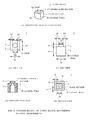
- a toy block which consists of a base section C3 having a parallelepiped shape with a hollow bottom and a cylindrical projection C2 projecting in a cylindrical shape from the base section C3, and in which assembly is enabled by interlocking the cylindrical projection C2 into the hollow portion of the base section C3, is conventionally known (see PTL 1, for example).
- the present invention provides a toy block that may improve the freedom of assembly.
- a toy block of the present invention is configured to include: a base section configured such that, taking the unit edge length to be 1 and a cube expressed as 1 x 1 x 1 to be one unit size, the base section has a parallelepiped shape of size approximately equal to one or more conjoined unit sizes, and is composed of an open, hollow face taken to be the bottom, four lateral walls, and a roof; and cylindrical projections of cylindrical shape provided on the outer face of one or more of the roof and the lateral walls, with a diameter being equal to or greater than 0.4 but less than 0.6 with respect to the unit edge length, and a height being (1 - diameter) x (0.4 to 0.5 inclusive); wherein the base section has an interlocking section that is enclosed by the four lateral walls, and by contacting and interlocking with other cylindrical projections of identical shape to the cylindrical projections with respect to at least one of the lateral walls, holds the other cylindrical projections; and the wall thickness near the bottom of the lateral walls is expressed as approximately (1
- cylindrical projections projecting in the vertical direction and the horizontal direction do not collide with each other, and additionally, cylindrical projections projecting in the horizontal direction are able to firmly hold other blocks.
- the present invention in the toy block, even in the case where cylindrical projections project in the horizontal direction, cylindrical projections projecting in the vertical direction and the horizontal direction do not collide with each other, and additionally, cylindrical projections projecting in the horizontal direction are able to firmly hold other blocks. In this way, the present invention is able to realize a toy block that may improve the freedom of assembly.
- the base section C3 is formed in a parallelepiped shape.
- the cylindrical projection C2 is formed with a diameter Cd3 of 5.0 mm and a height Cd4 of 3.5 mm.
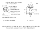
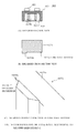
- a lateral wall cylindrical projection C2x on the lateral wall C3B of this 1-unit block C1 of conventional type will be described.
- another block some other block (hereinafter called “another block") is assembled with respect to the lateral wall cylindrical projection C2x, a step is formed between the base sections C3. If another block is assembled, a ubiquitous gap is formed between 1-unit blocks C1 due to the lateral wall cylindrical projection C2x contacting the lateral wall C3B of the base section C3.
- the projecting portion of the lateral wall cylindrical projection C2x interlocks inside the lateral walls C3B of the base section C3 of another block.
- the lateral walls C3B of the other block's base section C3 hang off the lateral wall cylindrical projection C2x, simply decreasing size of the lateral wall cylindrical projection C2x leads to the lateral wall cylindrical projection C2x becoming unable to support another block.
- a toy block of the first through third embodiments comprises combining blocks of various units, such as 1-unit blocks, 2-unit blocks, 4-unit blocks, 8-unit blocks, 16-unit blocks, 32-unit blocks, and 64-unit blocks, and the present invention is applied to each unit block.
- the units of a block may be a natural number, the value of which is not restricted. Note that the size tolerance is plus or minus 1.0%.
- toy blocks may also include unusual blocks with unusual shapes.
- toy blocks may also include unusual blocks with unusual shapes.
- highly elastic plastic such as ABS (Acrylonitrile-Butadiene-Styrene copolymer) plastic or acrylic plastic is used for all toy blocks.
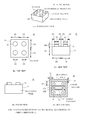
- Fig. 2 illustrates an overall configuration of a 1-unit block in the present embodiment.
- the 1-unit block has a base section 3 with a parallelepiped shape overall, and a cylindrical projection 2 with a cylindrical shape that projects from the roof 3A of the base section 3.
- the unit edge length D1 of the base section 3 is 6.0 mm, or in other words, the unit size is 6.0 x 6.0 x 6.0 mm.
- the cylindrical projection 2 has a diameter D2 that is 1/2 the unit edge length D1, or 3.0 mm, and a projection height D4 that is 1/2 the diameter D2, or 1.5 mm.
- the cylindrical projection 2 is chamfered along the edge of the circle on the upper face.
- the 1-unit block 1 has a hollow bottom.
- the 1-unit block 1 consists of one roof 3A and four lateral walls 3B, with the cylindrical projection 2 projecting from the roof 3A.
- the cylindrical projection 2 is provided at the center of the roof 3A, and the distance D3 from a lateral wall 3B to the edge of the cylindrical projection 2 is 1.5 mm in all cases. Note that the projection hole section 6 is not necessary.
- the space of an interlocking section 5 formed by the four lateral walls 3B and a projection hole section 6 are joined.
- the lateral walls 3B have an approximately uniform thickness overall, and that thickness T1 is 1/4 the unit edge length D1, or 1.5 mm.
- the horizontal inter-wall distance D5 of the interlocking section 5 ( Fig. 2(E) ) is 1/2 the unit edge length D1 in every horizontal direction, or in other words identical to the diameter D2 of the cylindrical projection 2. Consequently, when a cylindrical projection 2 is inserted into the interlocking section 5, that cylindrical projection 2 makes a 4-point contact on the inner faces of the lateral walls 3B constituting the interlocking section 5, and it becomes possible for the base section 3 to hold the cylindrical projection 2.
- the size of the interlocking section 5 in the horizontal direction is 3.0 mm x 3.0 mm.
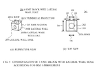
- Fig. 3 illustrates a 1-unit block with a lateral wall projection 101.
- the 1-unit block with a lateral wall projection 101 has a lateral wall cylindrical projection 102x, of identical shape and identical size as the cylindrical projection 102, on a lateral wall with a projection 103Ba, which is one of the lateral walls among the four lateral walls 103B.
- the 1-unit block with a lateral wall projection 101 is able to interlock not only the cylindrical projection 102 on the roof 103A of another block but also its lateral wall cylindrical projection 102x with the interlocking section 5 of another block, making it possible to hold a total of two other blocks.
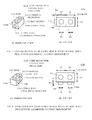
- the 1-unit block with a lateral wall projection 101 it becomes possible for the direction of blocks which could only be built upwards in the past to be assembled in two directions, as illustrated in Fig. 4(A) .
- Fig. 5 illustrates a 1-unit block with a lateral wall hole 201.
- the 1-unit block with a lateral wall hole 201 has a lateral wall hole 209 joined to the space of the interlocking section 205 (not illustrated) on a lateral wall with a hole 203Bb, which is one of the lateral walls among the four lateral walls 203B.
- the diameter D6 of the lateral wall hole 209 may be appropriately chosen according to material properties or wall thickness, but is nearly identical to the diameter D2, preferably plus or minus 3% of the diameter D2. In this embodiment, the diameter D6 is 3.0 mm and equal to the diameter D2 of the cylindrical projection 102. Also, the depth of the lateral wall hole 209 is equal to the wall thickness T1 of the lateral walls 203B (1.5 mm).
- the 1-unit block with a lateral wall hole 201 is able to accept the insertion of a cylindrical projection on another block at not only its interlocking section 205 (not illustrated), but also its lateral wall hole 209.
- assembly becomes possible in which the direction of blocks, which could only be built in one direction in the past, is changed to a difference direction, as illustrated in Fig. 4(B) .
- a 1-unit block with a lateral wall projection 101 and a 1-unit block with a lateral wall hole 201 in a toy block of this embodiment by including a 1-unit block with a lateral wall projection 101 and a 1-unit block with a lateral wall hole 201 in a toy block of this embodiment, the direction of cylindrical projections 2 can be increased and the direction of cylindrical projections 2 can be changed, therefore the freedom of assembly of the toy blocks can be significantly improved.
- the projection height D4 be less than or equal to ⁇ (unit edge length D1 - diameter D2) / 2 ⁇ .
- the 1-unit block with a lateral wall projection 101 will support a 1-unit block engaged in the horizontal direction.
- the lateral wall cylindrical projection 102 makes linear contact on the inner faces of the lateral walls 3B of another block. For this reason, at first glance it appears that the holding strength of a 1-unit block engaged in the horizontal direction can be raised by increasing the projection height D4 (see Fig. 2(C) ) as much as possible.
- an increase in the projection height D4 requires an equivalent decrease in the diameter D2. If the diameter D2 is overly decreased, the cylindrical projection 2 becomes needle-like, and the danger of puncturing one's hand may occur. Also, if the diameter D2 is decreased, the wall thickness T1 must be increased, requiring large amounts of material.
- the cylindrical projection 2 does not become needle-like, and safety as a toy can be guaranteed. Also, it is further preferable for the diameter D2 with respect to the unit edge length D1 to be 0.45 or greater, in order to maintain the external appearance as a toy block.
- a comparatively large wall thickness T1 can be ensured.
- a cylindrical projection projecting in the horizontal direction can suitably hold another block without the lateral walls 3B deforming, even in cases where additional weight from the lateral walls 3B is applied due to their own weight, etc.
- the thickness of the wall thickness T1 be less than 0.55.
- D1 1
- D2 the diameter of the cylindrical projection 2
- D4 the projection height
- T1 the wall thickness
- a 2-unit block 11 has an outward shape like that of two 1-unit blocks 1 lined up.
- the 2-unit block 11 has a base section 13 with a parallelepiped shape and two cylindrical projections 12.
- the cylindrical projections 12 have an identical shape to the cylindrical projection 2 of the 1-unit block 1.
- the base section 13 has the size of two conjoined 1-unit sizes, with edges in the one horizontal direction and the height being equal to the unit edge length D1, while the edges in the other horizontal direction is twice the unit edge length D1.
- the length x width x height 6.0 mm x 12.0 mm x 6.0 mm
- the wall thickness T1 1.5 mm
- the distance D3 1.5 mm.
- the 2-unit block 11 has an interlocking section 15 formed by the inner faces of the four lateral walls 13B. Specifically, the size of the interlocking section 15 in the horizontal direction is 3.0 mm x 9.0 mm. If the cylindrical projection of another block is inserted into this 2-unit block 11, the cylindrical projection and the lateral walls 13B contact at three points, holding the other block.
- a lateral wall cylindrical projection 112x is provided on a lateral wall with a projection 113Ba having the short edge in the horizontal direction from among the four lateral walls 113B.
- the shape of the lateral wall cylindrical projection 112x is identical to the cylindrical projections 12.
- two lateral wall cylindrical projections 112x are provided on a lateral wall with projections 113Ba having the long edge in the horizontal direction from among the four lateral walls 113B.
- respective lateral wall holes 219 are provided on a lateral wall with holes 213Bb having the short edge or long edge in the horizontal direction from among the four lateral walls 213B, similarly to the 2-unit blocks with lateral wall projections 111A and 111B.
- the shapes of the lateral wall holes 219 are identical to the lateral wall hole 209 of the 1-unit block with a lateral wall hole 201.
- an 8-unit block 21 has an outward shape of eight 1-unit blocks 1 lined up.
- the 8-unit block 21 has a base section 23 with a parallelepiped shape and eight cylindrical projections 22.
- the cylindrical projections 22 have an identical shape to the cylindrical projection 2 of the 1-unit block 1.
- the 8-unit block 21 has an interlocking section 25 formed by the inner faces of the four lateral walls 23B.
- the size of the interlocking section 25 in the horizontal direction is 21.0 mm x 9.0 mm.
- a middle partition 27 that constitutes the interlocking section 25 together with the lateral walls 23B is formed on the centerline in the longer direction. Insertion of cylindrical projections is made easier by having the middle partition 27 be slightly shorter than the lateral walls 23B in the height direction.
- the middle partition 27 is composed of two long walls 27A in the longer direction, and four short walls 27B that are orthogonal to the long walls 27A and join the two long walls 27A.
- the four cylindrical projections positioned at the ends in the longer direction and the lateral walls 23B contact at three points. Meanwhile, the other block is held such that the four cylindrical projections positioned inwardly in the longer direction and the lateral walls 23B contact at two points.
- the short walls 27B are provided at the portions where the cylindrical projections of another block and the long walls 27A contact, and suppress deformation of the long walls 27A due to additional weight from those cylindrical projections.
- the middle partition 27 is made to keep its strength as a middle partition 27 while reducing material usage.
- the long walls 27A may also be in a state of extending out past the short walls 27B.
- a 4-unit block 31 has an outward shape of four 1-unit blocks 1 lined up.
- the 4-unit block 31 has a base section 33 with a parallelepiped shape and four cylindrical projections 32.
- the cylindrical projections 32 have an identical shape to the cylindrical projection 2 of the 1-unit block 1.
- edges in the horizontal direction are equal to twice the unit edge length D1.
- the length x width x height 12.0 mm x 12.0 mm x 6.0 mm
- the wall thickness T1 1.5 mm
- the distance D3 1.5 mm.
- the 4-unit block 31 has a middle partition 37 inside the interlocking section 35 formed by the inner faces of the four lateral walls 33B.
- the length of the middle partition 37 in the height direction is identical to the middle partition 27 in the 8-unit block 21.
- the middle partition 37 has an I-shaped construction, it may also be a hollow rectangle similar to the middle partition 27.
- lateral wall cylindrical projections 122x are provided on a lateral wall with projections 123Ba having the long edge in the horizontal direction from among the four lateral walls 123B.
- the shape of the lateral wall cylindrical projections 122x is identical to the cylindrical projections 12.
- two lateral wall cylindrical projections 122x may also be provided on a lateral wall with projections 123Ba having the short edge in the horizontal direction from among the four lateral walls 123B.
- the 4-unit block with lateral wall projections 131 is also similar, and two lateral wall cylindrical projections 132x may be provided on any lateral wall with projections 133Ba.
- lateral wall holes 229 are provided on a lateral wall with holes 223Bb having the long edge in the horizontal direction from among the four lateral walls 223B, similarly to the 8-unit block with lateral wall projections 121.
- the shape of the lateral wall holes 229 is identical to the lateral wall hole 209 of the 1-unit block 201.
- two lateral wall holes 229 may also be provided on a lateral wall with holes 223Bb having the short edge in the horizontal direction from among the four lateral walls 223B.
- two lateral wall holes 239 are provided on a lateral wall with holes 233Bb, which is one edge in the horizontal direction from among the four lateral walls 233B, similarly to the 4-unit block with lateral wall projections 131.
- the shape of the lateral wall holes 239 is identical to the lateral wall hole 209 of the 1-unit block 201.
- lateral wall cylindrical projections may also be formed on two or more lateral walls, they are preferably formed on only one. This is because construction as a toy block cannot become simplistic if lateral wall cylindrical projections are formed on multiple faces.
- Lateral wall holes are also similar, and although they may be formed on two or more lateral walls, they are preferably formed on only one. This is because the appearance as a toy block can be kept by not outwardly exposing unused lateral wall holes.
- a 16-unit block 51 has an outward shape of sixteen 1-unit blocks 1 lined up.
- the 16-unit block 51 has a base section 53 with a parallelepiped shape and sixteen cylindrical projections 52.
- the cylindrical projections 52 have an identical shape to the cylindrical projection 2 of the 1-unit block 1.
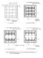
- Middle partitions 57X may be provided on every row as part of the interlocking section 55, as illustrated in Fig. 15(B) , or middle partitions 57Y may also be partially provided, as illustrated in Fig. 15(C) .
- middle partitions 57Z may also be configured with just one long wall 57A, as illustrated in Fig. 15(D) .
- These configurations of middle partitions 57 may also be applied to blocks of any units, such as 4-, 8-, and 32-unit blocks.
- the base section 3 of the 1-unit block 1 of the present invention is configured such that, taking the unit edge length D1 to be 1 and a cube expressed as 1 x 1 x 1 to be one unit size, or in other words a 1-unit block 1, the base section 3 has a parallelepiped shape in which one or multiple unit sizes are conjoined, being composed of an open, hollow face taken to be the bottom, four lateral walls 3B, and a roof 3A.
- the cylindrical projection 2 has a cylindrical shape and is provided on the outer face of one or more of the roof 3A and lateral walls 3B, with its diameter D2 being equal to or greater than 0.4 but less than 0.6 with respect to the unit edge length D1, and its height being (1 - diameter) x (0.4 to 0.5 inclusive).
- the interlocking section 5 is enclosed by the four lateral walls 3B, and by contacting and interlocking with another cylindrical projection X2 of identical shape to the cylindrical projection 2 with respect to at least one of the lateral walls 3B, holds that cylindrical projection X2.
- the wall thickness T1 near the bottom of a lateral wall 3B contacting and holding the other cylindrical projection X2 is expressed as (1 - diameter) x 0.5 + alpha, where alpha is between -0.05 and 0.03 inclusive, and more preferably, alpha is between -0.02 and 0.01 inclusive. Stated differently, the wall thickness T1 is approximately (1 - diameter) x 0.5.
- an alpha may occur in the case of uniformly reducing the dimensions of the base section in each unit block from their unit sizes, or in the case of designing the inter-wall distance D5 to be less than the diameter D2, for example, and in the present embodiment, the alpha is zero.
- the other cylindrical projection X2 can be firmly held by the holding force due to the balance between the diameter D2 and height D4 of the other cylindrical projection X2 as well as the thickness of the wall thickness T1, even though the size of the other cylindrical projection X2 is small due to constraints for projecting cylindrical projections 2 vertically and horizontally.
- the cylindrical projection 2 has a diameter that is equal to or greater than 0.45 but less than 0.55, and a height that is (1 - diameter) x (0.45 to 0.5 inclusive).
- the 1-unit block 1 is able to hold another cylindrical projection X2 much more reliably due to this balance.
- the parallelepiped shape of the base section 23 consists of a shape of conjoined unit sizes of at least 2 x 2 or greater, while the interlocking section 25 has a middle partition 27 that contacts other cylindrical projections X2 in the interlocking section enclosed by the four lateral walls 23B.
- other cylindrical projections X2 can be reliably held, even in a unit block having two or more rows of cylindrical projections 22 in the shorter direction, such as the 8-unit block 21, for example.
- a lateral wall cylindrical projection 102x of nearly identical size as the cylindrical projection 102 is provided on at least one of the four lateral walls 103B.
- other blocks can be assembled not just vertically but also horizontally, potentially improving the freedom of assembly.
- a lateral wall hole 209 of nearly identical size as the cylindrical projection 202 is provided on at least one of the four lateral walls 203B.
- diameter D2 is slightly smaller than inter-wall distance D5 preferably, since the interlocking section 5 can hold the cylindrical projection 2 more reliably.
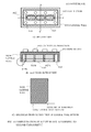
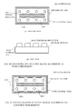
- Figs. 16 to 18 illustrate a second embodiment which differs from the first embodiment illustrated in Figs. 2 to 15 in that a step is provided on the inner faces of the lateral walls 1023B, and in the configuration of the middle partition 1027. Note that in the second embodiment, signs with 1000 added are attached to portions that correspond to the first embodiment.
- the lateral walls 1023B are formed such that the angle between the inner face of a lateral wall 1023B and a lateral wall bottom 1023Ba at the bottom is cut out on the inner side of the lateral wall bottom 1023Ba, and the cross section has a rectangular inner depression 1023Bb.
- This inner depression 1023Bb is provided along the inner side of the four lateral walls 1023B enclosing the interlocking section 1025, with one edge being 0.1 to 0.3 mm.
- the shape of the inner depression 1023Bb is not restricted, and the cross section may also have a triangular or circular cutout.
- the long walls 1027A of the middle partition 1027 have outwardly bulging outward protrusions 1027Ab at each region that does not interlock with the cylindrical projection X2 of another block, which thereby form depressed interlocking depressions 1027Ac only in regions where a cylindrical projection X2 interlocks.
- a boundary line 1027Aa is taken to be the extension extending parallel to a long wall 1027A from the region of the long wall 1027A that is farthest away from the lateral walls 1023B (in other words, the maximally depressed part of an interlocking depression 1027Ac).
- the inter-wall distance D11 from the boundary line 1027Aa to the inner face of a lateral wall 1023B is formed slightly smaller (2.7 mm ⁇ 2.9mm, for example) than the diameter D2 (3.0mm) of a cylindrical projection 1022.
- the outward protrusions 1027Ab project approximately 0.5 mm to 2.0 mm from the boundary line 1027Aa at their maximally protruding part.
- the opening distance D12 from the intersection point of the lateral wall bottom 1023Ba in the inner depression 1023Bb ( Fig. 16(C) ) to the boundary line 1027Aa ( Fig. 17(B) ) is formed equal to the diameter D2 or slightly larger (3.0 to 3.1 mm, for example) than the diameter D2.
- the outward protrusions 1027Ab are formed to project slightly from the region farther inward than the boundary line 1027Aa of a long wall 1027A (0.1 to 0.3 mm, for example), with their tips being formed at positions identical to or slightly inward (inward by 0.0 mm to 0.1 mm, for example) from the lateral wall bottom 1023Ba.
- the distance D13 from the outward protrusions 1027Ab to the lateral wall bottom 1023Ba is formed smaller than the diameter D2 of a cylindrical projection X2.
- cylindrical projections X2 naturally fit inside the interlocking depressions 1027Ac, and are guided to suitable positions inside the interlocking section 1025.
- cylindrical projections X2 temporarily catch inside the inner depression 1023Bb, since the step is small, they are easily inserted deeper past the inner depression 1023Bb by the user's pushing action. Since the inter-wall distance D11 is smaller than the diameter D2 of a cylindrical projection X2, the lateral walls 1023B continuously push against the cylindrical projections X2, firmly holding them.
- the wall thickness T1 is designed to be sufficiently thick, there is little risk of plastic deformation of the lateral walls 1023B. Additionally, there is little risk of plastic deformation due to the short walls 1027B provided at the portions that contact a cylindrical projection X2 in the middle partition 1027.
- the interlocking depressions 1027Ac are trapezoidal depressions, and the legs of the trapezoid have a gentler slope than the curvature of a cylindrical projection X2. For this reason, an interlocking depression 1027Ac is able to contact a cylindrical projection X2 only at its maximally depressed point (line) and hold that cylindrical projection X2.
- the interlocking depression 1027Ac is configured such that the interlocking depression 1027Ac begins to slope and the distance between the interlocking depression 1027Ac and the lateral wall 1023B shortens before contact is made inside the interlocking depression 1027Ac at sites other than the contact point W. For this reason, the cylindrical projection X2 is substantially unable to move left or right, and its contact point with the interlocking depression 1027Ac becomes just one point.
- interlocking depressions 1027Ac may also be such that the angled portions of the trapezoid are curved as in Fig. 17(C) , or circular. It is sufficient for the sloped portions to be gentler than the curve of a cylindrical projection X2.
- an 8-unit block 1021 it is configured such that the outward protrusions 1027Ab are included on at least one face of the long walls 1027A.
- the outward protrusions 1027Ab acts as a guide mechanism and the position where other cylindrical projections X2 contact on the boundary line 1027Aa is maximally depressed.
- the 8-unit block 1021 is able to moderately maintain holding force on another interlocked unit block without increasing the contact point between the other cylindrical projections X2 and the long walls 1027A and without the other cylindrical projections X2 becoming misaligned in the horizontal direction. It is also possible to prevent the holding force from becoming excessive due to the increased number of cylindrical projections 1022.
- the inter-wall distance D11 from a lateral wall 1023B to a long wall 1027A where one other cylindrical projection should be interlocked is formed slightly smaller than the diameter D2 of a cylindrical projection 1022.
- the inter-wall distance D5 between two lateral walls is formed slightly smaller than the diameter D2 of a cylindrical projection 1022 in the case of a unit block with one row on its shorter edge.
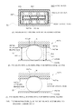
- Figs. 20 and 21 illustrate a third embodiment which differs from the second embodiment illustrated in Figs. 16 to 18 in the wall thickness T1 and the size of the cylindrical projection 2022 and in that the middle partition 2027 lacks short walls. Note that in the third embodiment, signs with 1000 added are attached to portions that correspond to the second embodiment.
- the middle partition 2027 of the second embodiment is applied to the 8-unit block 2021 of identical configuration as a conventional unit block C21.
- the cylindrical projection C2 is formed with a diameter Cd3 of 5.0 mm and a height Cd4 of 3.5 mm, while the wall thickness of the lateral walls 2023B is 1.5 mm.
- the middle partition 2027 is configured with two long walls 2027A only, and lacks short walls.
- plastic with comparatively high flexibility such as polypropylene plastic or styrene plastic, for example, plastic deformation can be prevented even without short walls.
- the wall thickness T1 near the bottom of the lateral walls 2023B is expressed as approximately (1 - diameter) x 0.5 + alpha, where alpha is between -0.05 and 0.03 inclusive.
- the 8-unit block 2021 is provided with outward protrusions 2023Bb as a guide mechanism on at least one face of the lateral walls 2023B and the long walls 2027A constituting the interlocking section 2025.
- the 8-unit block 2021 is able to moderately maintain holding force on another interlocked unit block without the other cylindrical projections 20X2 becoming misaligned in the horizontal direction. It is also possible to prevent the holding force from becoming excessive due to the increased number of cylindrical projections 2022.
- outward protrusions 1027Ab on the 8-unit block 1021 was described.
- the present invention is not limited thereto, and the outward protrusions 1027Ab may be applied to all blocks with two or more rows of cylindrical projections, such as 4, 6, 10, 12, 16, and so on.
- the outward protrusions 2027Ab may be applied to unit blocks consisting of various numbers.
- the present invention is not limited thereto, and is unrestricted insofar as it is within the size range of the present invention.
- sizes which are a natural number multiple of the 1-unit size it is also possible to form blocks which are smaller by a given size (0.1 mm, for example) in just the horizontal direction.
- a 1-unit block becomes 5.9 x 5.9 x 6.0 mm in size
- a 2-unit block becomes 5.9 x 11.9 x 6.0 mm in size
- a 4-unit block becomes 11.9 x 11.9 x 6.0 mm in size.
- the present invention can be utilized for various toy blocks which can be assembled.
Landscapes
- Toys (AREA)
Applications Claiming Priority (2)
| Application Number | Priority Date | Filing Date | Title |
|---|---|---|---|
| JP2012134281 | 2012-06-13 | ||
| PCT/JP2012/082585 WO2013186955A1 (ja) | 2012-06-13 | 2012-12-15 | 玩具用ブロック |
Publications (2)
| Publication Number | Publication Date |
|---|---|
| EP2835162A1 true EP2835162A1 (de) | 2015-02-11 |
| EP2835162A4 EP2835162A4 (de) | 2016-03-16 |
Family
ID=49757811
Family Applications (1)
| Application Number | Title | Priority Date | Filing Date |
|---|---|---|---|
| EP12878811.4A Withdrawn EP2835162A4 (de) | 2012-06-13 | 2012-12-15 | Spielklotz |
Country Status (6)
| Country | Link |
|---|---|
| US (1) | US9849398B2 (de) |
| EP (1) | EP2835162A4 (de) |
| JP (1) | JP6158803B2 (de) |
| CN (1) | CN104487146B (de) |
| TW (1) | TWI576142B (de) |
| WO (1) | WO2013186955A1 (de) |
Cited By (1)
| Publication number | Priority date | Publication date | Assignee | Title |
|---|---|---|---|---|
| US20210170296A1 (en) * | 2017-11-08 | 2021-06-10 | Lego A/S | Toy building set |
Families Citing this family (9)
| Publication number | Priority date | Publication date | Assignee | Title |
|---|---|---|---|---|
| US9345982B2 (en) | 2014-09-01 | 2016-05-24 | Joseph Farco | Building block universal joint system |
| US10232279B2 (en) * | 2015-12-18 | 2019-03-19 | Reginald Frederick Woolston | Modular cube building system |
| KR101758781B1 (ko) | 2016-01-25 | 2017-07-17 | (주)버블블록 | 조립식 블록 기초판 및 조립식 블록 기초판 조립체 |
| USD834104S1 (en) | 2017-04-26 | 2018-11-20 | Mattel-Mega Holdings (Us), Llc | Construction set element |
| USD834105S1 (en) | 2017-06-01 | 2018-11-20 | Mattel-Mega Holdings (Us), Llc | Construction set element |
| US10518189B2 (en) * | 2017-09-20 | 2019-12-31 | Mattel-Mega Holdings (Us), Llc | Tool for use with toy construction elements |
| US11964883B2 (en) * | 2020-08-06 | 2024-04-23 | Jonathan Hendrik Van Ee | Gigacubes solar still |
| US11565192B2 (en) * | 2020-08-06 | 2023-01-31 | Jonathan Hendrik Van Ee | Letter cubes |
| US12594509B2 (en) | 2023-08-19 | 2026-04-07 | Farco ToyCo LLC | Interconnecting methods and systems for posable bendable building block toys |
Family Cites Families (22)
| Publication number | Priority date | Publication date | Assignee | Title |
|---|---|---|---|---|
| US3162973A (en) * | 1961-06-27 | 1964-12-29 | Interlego Ag | Toy building element |
| GB1008459A (en) * | 1962-06-09 | 1965-10-27 | Hasel Heinz | Hollow box-shaped toy building elements |
| DE1478447B1 (de) * | 1963-07-26 | 1970-02-12 | Hoewe August W | Baukastenspiel |
| FR1415559A (fr) | 1964-06-29 | 1965-10-29 | Le Jouet Francais | éléments perfectionnés pour jeux de construction |
| JPS4511321Y1 (de) * | 1967-11-18 | 1970-05-20 | ||
| CH495762A (de) | 1968-06-05 | 1970-09-15 | Bartoeck Minnaard Maatje | Bausatz-Spielzeug |
| CA1046767A (en) * | 1975-11-19 | 1979-01-23 | Altro, Stephen | Interlocking toy building element |
| JPS5415759Y2 (de) | 1975-11-21 | 1979-06-23 | ||
| GB1585436A (en) * | 1978-04-15 | 1981-03-04 | Lin Wen Pin | Building blocks |
| GB2118447B (en) | 1982-04-14 | 1985-10-23 | Kassai Kk | Block toy |
| US4744780A (en) * | 1986-02-06 | 1988-05-17 | Tyco Industries, Inc. | Adapter block |
| JPH05277262A (ja) * | 1992-03-30 | 1993-10-26 | Tanishita Kogyo Kk | 組立ブロックセット |
| IT1257727B (it) | 1992-11-03 | 1996-02-13 | Struttura di mattonella, particolarmente per l'edilizia | |
| TW373517U (en) | 1994-09-29 | 1999-11-01 | Interlego Ag | Stackable block system |
| IL121303A0 (en) * | 1997-07-14 | 1998-01-04 | Reisman Ron | Toy building blocks |
| TW436310B (en) * | 1999-01-15 | 2001-05-28 | Interlego Ag | A building element for a toy building set |
| US8105128B1 (en) * | 2006-02-10 | 2012-01-31 | Soerensen Soeren Christian | Injection molded toy building element |
| CN2870929Y (zh) * | 2006-03-01 | 2007-02-21 | 马达伟 | 一种智力玩具 |
| JP2010172568A (ja) | 2009-01-30 | 2010-08-12 | Kawada Co Ltd | ブロック玩具 |
| DE202011109611U1 (de) * | 2011-12-27 | 2012-03-15 | Shiarn Fur Industry Co., Ltd. | Baustein |
| US8771032B2 (en) * | 2012-03-23 | 2014-07-08 | Delsun Co., Ltd. | Block assembly |
| US20140220854A1 (en) * | 2013-02-07 | 2014-08-07 | Yang-Chih Lee | Adaptor brick |
-
2012
- 2012-12-15 WO PCT/JP2012/082585 patent/WO2013186955A1/ja not_active Ceased
- 2012-12-15 US US14/407,030 patent/US9849398B2/en active Active
- 2012-12-15 JP JP2014521199A patent/JP6158803B2/ja active Active
- 2012-12-15 CN CN201280073662.0A patent/CN104487146B/zh active Active
- 2012-12-15 EP EP12878811.4A patent/EP2835162A4/de not_active Withdrawn
-
2013
- 2013-01-29 TW TW102103337A patent/TWI576142B/zh not_active IP Right Cessation
Cited By (1)
| Publication number | Priority date | Publication date | Assignee | Title |
|---|---|---|---|---|
| US20210170296A1 (en) * | 2017-11-08 | 2021-06-10 | Lego A/S | Toy building set |
Also Published As
| Publication number | Publication date |
|---|---|
| US9849398B2 (en) | 2017-12-26 |
| EP2835162A4 (de) | 2016-03-16 |
| HK1205038A1 (zh) | 2015-12-11 |
| CN104487146B (zh) | 2016-06-29 |
| TWI576142B (zh) | 2017-04-01 |
| WO2013186955A1 (ja) | 2013-12-19 |
| US20150174502A1 (en) | 2015-06-25 |
| JP6158803B2 (ja) | 2017-07-05 |
| JPWO2013186955A1 (ja) | 2016-02-01 |
| TW201404445A (zh) | 2014-02-01 |
| CN104487146A (zh) | 2015-04-01 |
Similar Documents
| Publication | Publication Date | Title |
|---|---|---|
| EP2835162A1 (de) | Spielklotz | |
| EP3703587B1 (de) | Modulare chirurgische klammerkassette | |
| KR200486692Y1 (ko) | 이중 레이어를 구비한 전자 기기용 케이스 | |
| ES2317318T3 (es) | Conector enchufable para placas de circuito impreso. | |
| KR101108922B1 (ko) | 길이 조절이 가능한 칸막이 | |
| JP6648661B2 (ja) | プロテクタ付ワイヤーハーネス | |
| JPWO2013011672A1 (ja) | トレイ | |
| KR20160085775A (ko) | 건축 키트 구성요소(변형들) 및 건축 키트 | |
| JP2022101649A (ja) | 光ファイバホルダ | |
| KR102158260B1 (ko) | 배터리 팩의 외부 충/방전 커넥터와 연결되는 접속부 구조 | |
| HK1205038B (en) | Toy block | |
| KR20120104052A (ko) | 슬라이드 적층형 수납용기의 적층구조 및 적층보관장치 | |
| JP2003230445A (ja) | 長さ調節可能な仕切具 | |
| JP6018371B2 (ja) | 板材を使用した収納ラック | |
| CN214208011U (zh) | 一种收纳篮 | |
| CN204902372U (zh) | 冰箱 | |
| CN217970388U (zh) | 食品容器 | |
| JP2022138632A (ja) | 棚 | |
| CN203450609U (zh) | 蛋盒的改良结构 | |
| KR20120104053A (ko) | 슬라이드 적층형 수납용기 | |
| JP3175852U (ja) | 包装容器用中仕切り及び該中仕切りを備えた包装容器 | |
| KR200184178Y1 (ko) | 냉장고의 선반 지지구조 | |
| JP2023154973A (ja) | ブロック玩具 | |
| KR20130080567A (ko) | 다양한 크기의 서랍을 다양한 방식으로 수납할 수 있는 서랍장 | |
| JP5469541B2 (ja) | バックル |
Legal Events
| Date | Code | Title | Description |
|---|---|---|---|
| PUAI | Public reference made under article 153(3) epc to a published international application that has entered the european phase |
Free format text: ORIGINAL CODE: 0009012 |
|
| 17P | Request for examination filed |
Effective date: 20141021 |
|
| AK | Designated contracting states |
Kind code of ref document: A1 Designated state(s): AL AT BE BG CH CY CZ DE DK EE ES FI FR GB GR HR HU IE IS IT LI LT LU LV MC MK MT NL NO PL PT RO RS SE SI SK SM TR |
|
| AX | Request for extension of the european patent |
Extension state: BA ME |
|
| DAX | Request for extension of the european patent (deleted) | ||
| RA4 | Supplementary search report drawn up and despatched (corrected) |
Effective date: 20160212 |
|
| RIC1 | Information provided on ipc code assigned before grant |
Ipc: A63H 33/08 20060101AFI20160208BHEP |
|
| STAA | Information on the status of an ep patent application or granted ep patent |
Free format text: STATUS: EXAMINATION IS IN PROGRESS |
|
| 17Q | First examination report despatched |
Effective date: 20170404 |
|
| STAA | Information on the status of an ep patent application or granted ep patent |
Free format text: STATUS: THE APPLICATION IS DEEMED TO BE WITHDRAWN |
|
| 18D | Application deemed to be withdrawn |
Effective date: 20170815 |