EP2835488A2 - Porte à feuilles - Google Patents
Porte à feuilles Download PDFInfo
- Publication number
- EP2835488A2 EP2835488A2 EP20140002780 EP14002780A EP2835488A2 EP 2835488 A2 EP2835488 A2 EP 2835488A2 EP 20140002780 EP20140002780 EP 20140002780 EP 14002780 A EP14002780 A EP 14002780A EP 2835488 A2 EP2835488 A2 EP 2835488A2
- Authority
- EP
- European Patent Office
- Prior art keywords
- slot
- edge
- door
- foil
- film
- Prior art date
- Legal status (The legal status is an assumption and is not a legal conclusion. Google has not performed a legal analysis and makes no representation as to the accuracy of the status listed.)
- Granted
Links
Images

Classifications
-
- E—FIXED CONSTRUCTIONS
- E06—DOORS, WINDOWS, SHUTTERS, OR ROLLER BLINDS IN GENERAL; LADDERS
- E06B—FIXED OR MOVABLE CLOSURES FOR OPENINGS IN BUILDINGS, VEHICLES, FENCES OR LIKE ENCLOSURES IN GENERAL, e.g. DOORS, WINDOWS, BLINDS, GATES
- E06B3/00—Window sashes, door leaves, or like elements for closing wall or like openings; Layout of fixed or moving closures, e.g. windows in wall or like openings; Features of rigidly-mounted outer frames relating to the mounting of wing frames
- E06B3/70—Door leaves
- E06B3/80—Door leaves flexible
-
- E—FIXED CONSTRUCTIONS
- E04—BUILDING
- E04G—SCAFFOLDING; FORMS; SHUTTERING; BUILDING IMPLEMENTS OR AIDS, OR THEIR USE; HANDLING BUILDING MATERIALS ON THE SITE; REPAIRING, BREAKING-UP OR OTHER WORK ON EXISTING BUILDINGS
- E04G21/00—Preparing, conveying, or working-up building materials or building elements in situ; Other devices or measures for constructional work
- E04G21/24—Safety or protective measures preventing damage to building parts or finishing work during construction
- E04G21/241—Safety or protective measures preventing damage to building parts or finishing work during construction for temporarily closing door or window openings
-
- E—FIXED CONSTRUCTIONS
- E04—BUILDING
- E04G—SCAFFOLDING; FORMS; SHUTTERING; BUILDING IMPLEMENTS OR AIDS, OR THEIR USE; HANDLING BUILDING MATERIALS ON THE SITE; REPAIRING, BREAKING-UP OR OTHER WORK ON EXISTING BUILDINGS
- E04G21/00—Preparing, conveying, or working-up building materials or building elements in situ; Other devices or measures for constructional work
- E04G21/24—Safety or protective measures preventing damage to building parts or finishing work during construction
- E04G21/30—Safety or protective measures preventing damage to building parts or finishing work during construction against mechanical damage or dirt, e.g. guard covers of stairs
-
- E—FIXED CONSTRUCTIONS
- E04—BUILDING
- E04H—BUILDINGS OR LIKE STRUCTURES FOR PARTICULAR PURPOSES; SWIMMING OR SPLASH BATHS OR POOLS; MASTS; FENCING; TENTS OR CANOPIES, IN GENERAL
- E04H15/00—Tents or canopies, in general
- E04H15/32—Parts, components, construction details, accessories, interior equipment, specially adapted for tents, e.g. guy-line equipment, skirts, thresholds
- E04H15/58—Closures; Awnings; Sunshades
-
- E—FIXED CONSTRUCTIONS
- E04—BUILDING
- E04G—SCAFFOLDING; FORMS; SHUTTERING; BUILDING IMPLEMENTS OR AIDS, OR THEIR USE; HANDLING BUILDING MATERIALS ON THE SITE; REPAIRING, BREAKING-UP OR OTHER WORK ON EXISTING BUILDINGS
- E04G21/00—Preparing, conveying, or working-up building materials or building elements in situ; Other devices or measures for constructional work
- E04G21/24—Safety or protective measures preventing damage to building parts or finishing work during construction
- E04G2021/248—Tarpaulins specially adapted therefor
-
- E—FIXED CONSTRUCTIONS
- E06—DOORS, WINDOWS, SHUTTERS, OR ROLLER BLINDS IN GENERAL; LADDERS
- E06B—FIXED OR MOVABLE CLOSURES FOR OPENINGS IN BUILDINGS, VEHICLES, FENCES OR LIKE ENCLOSURES IN GENERAL, e.g. DOORS, WINDOWS, BLINDS, GATES
- E06B5/00—Doors, windows, or like closures for special purposes; Border constructions therefor
- E06B5/02—Doors, windows, or like closures for special purposes; Border constructions therefor for out-buildings or cellars; Other simple closures not designed to be close-fitting
- E06B5/025—Provisional closures, e.g. temporary security doors
Definitions
- the invention relates to a film door for temporarily closing a passage, comprising a film element of a flexible film material comprising at least one lower edge and at least two side edges, wherein the side edges adjoin the lower edge, as well as with a formed in the film element, emanating from the lower edge and An opening slit bounded by opposite slit edges and provided at at least one slit edge with closure means for fixing the other slit edge and comprising a plurality of slit sections.
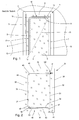
- a film door 1 can be used, for example, on a construction site to separate two adjacent spaces, between which a wall with a door cut-out 2 is arranged.
- a film element 5 is arranged in the door opening 2, which is bordered by a door frame 3 and a bottom 4.
- the film element 5 is fixed to opposite side edges 6, 7 and an upper edge 8 by means of double-sided adhesive tape on the door frame 3.
- a lower edge 9 of the film element 5 is by way of example no attachment to the bottom. 4 intended.
- the foil door 1 closes the door opening 2 relatively tightly and thus can effectively prevent the spread of dust or dirt, as may occur, for example, in the context of construction work through the door opening 2.
- an opening slot is introduced in the film element 5.
- the opening slot has a substantially L-shaped course, wherein the L is preferably placed upside down. Slot edges 10, 11 of the opening slot are bounded by a zipper 12, in the representation of the FIG. 1 is completely closed.
- a foil door provided with a C-shaped opening slot, wherein aligned C-legs are substantially parallel and are connected by a substantially vertically extending, straight formed slot portion.
- the object of the invention is to provide a foil door having an improved functionality.
- a first slot section emanating from the lower edge passes through a strip-shaped threshold area extending along the lower edge such that a subsequent second slot section runs along an upper threshold edge of the threshold area, such that a subsequent third slot section is at least substantially parallel to the first slot section in FIG Direction of the upper edge of the film element extends and that a subsequent fourth slot section at least substantially parallel and in the opposite direction to the second slot section.
- a partial opening results in a substantially rectangular passage at least when the opening slot is opened, starting from an end area of the fourth slot section to the second slot section, in particular up to a transition between the second slot section and the first slot section.
- a strip-shaped threshold area remains closed in the near-bottom region of the foil door, which at least significantly reduces carry-over of dust and dirt through the foil door.
- the threshold area is designed in its height so that it can be easily exceeded. A preferred height for the threshold range is about 15 centimeters to 20 centimeters.
- the region of the film door bordered by the second, third and fourth slot sections can be bent or pivoted about a line, preferably as an extension of the first slot section.
- the portion of the threshold area bordered by the first and second slot sections can be bent or pivoted, for example, around a line intended as an extension of the fourth slot section.
- objects can be pushed or rolled over the floor through the film door, or are transported through the film door, for example by means of a wheelbarrow.
- it can be provided to close the threshold area after such a transport by only the first slot section being closed again, in order to reduce the carryover of dust and dirt between the adjacent rooms.
- the second slot section is aligned parallel to the lower edge of the film element. This allows a preferably horizontal orientation of the realize second slot portion bordered threshold range, whereby a safe and convenient passage through the foil door is ensured. This assumes that the lower edge of the film element can be aligned horizontally when installing the film door.
- the fourth slot section is aligned parallel to the second slot section. This ensures that the passage through the foil door has the largest possible cross-section. Furthermore, a correct installation of the film door is facilitated in the door opening, since in this case the fourth slot portion can be aligned in a simple manner parallel to the usually horizontally extending lintel.
- the closure means is designed as a zipper which can be opened at the end, in particular on both sides, and transition regions between arcuate sections are formed in an arcuate manner. Due to the possibility of opening the zipper on the end side, the film element can be completely separated except for an area adjoining the fourth slot section in order to provide a maximum access.
- the zipper can be designed either as a toothed zipper or as a toothless zipper and has at least one slide, also referred to as a slide, which allows separation and connection of the two slot edges.
- carriages are respectively arranged on the opening slot at the end, so that the zipper can be opened both starting from the first slot section and from the fourth slot section.
- a partial Opening the film door is made using the slot associated with the fourth slot portion, while a complete opening of the film door using the first slot portion associated carriage takes place.
- two carriages are arranged such that a portion of the zipper is opened between the carriages, so that it can also be provided to fully open the second and fourth slot portions only partially and the third slot portion therebetween to a narrow one To determine in its width adjustable access through the foil door, without having to make major compromises in terms of safety and comfort for the passage.
- the first slot section passes through the strip-shaped threshold area off-center, in particular adjacent to a side edge. This ensures that when the first slot section is fully opened, a larger part of the strip-shaped threshold area can be pivoted to the side or folded.
- first slot section is arranged vertically below an end region of the fourth slot section. As a result, convenient pivoting or folding of a film area bounded by the second, third and fourth slot sections can be ensured.
- a C-shaped slot section adjoins a first slot section starting at the lower edge and passing through a strip-shaped threshold area extending along the lower edge.
- the C-shaped slot portion is preferably formed such that two rectilinear and mutually parallel legs define a straight line oriented transversely to the legs and at the transitions between the legs and the straight line and from a leg to the first slot portion curve sections are provided.
- the legs are aligned parallel to the lower edge and / or upper edge of the film element.
- the straight line is aligned parallel to at least one side edge.
- a holding means for releasably, in particular repeatedly detachable, connection with a door frame and / or a door sill is attached.
- This can be, for example, an adhesive strip, in particular a double-sided adhesive tape, a multiply releasable and closable connection such as a hook-and-loop fastener, a magnetic strip or an expandable hose arrangement or combinations thereof.
- a double-sided adhesive tape is mounted in order to permanently attach the film element in these areas in a door opening.
- the film element is rectangular with an upper edge, two side edges and a bottom edge is formed and that the slot portions are aligned parallel to at least one edge from the group: top edge, side edge, bottom edge.
- the things and the width of the film element are dimensioned so that most door cutouts can be closed with the film element.
- the film element can optionally be cut to size or adapted by suitable attachment of tape to smaller door openings.
- the film door can also be used for tents, in which case it may be provided to sew the film element edge with adjacent areas of a tarpaulin and / or to weld.
- the film element is triangular, thus has only a lower edge and two side edges, the side edges directly adjacent to each other and an upper edge is eliminated.
- a film element can be incorporated, for example, in a tarpaulin.
- film door 1 is a description of the inventive film doors 31, 61, 71th
- plastic materials such as plastic films, plastic fabrics or nonwoven fabrics are preferably used, which are in particular made of polyvinyl chloride or polyethylene or polypropylene or polyester or mixtures thereof. Other plastic materials or natural materials may also be used. It is possible that the material for the foil doors 31, 61, 71 is transparent and / or breathable. Depending on the intended use for the film door can also be provided that the material for the film door is provided with a coating and / or is formed as a laminate of different or similar material layers.
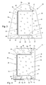
- the illustrated in the figure two first embodiment of a film door 31 comprises a film element 32, which is formed by way of example rectangular.
- the film element 32 has a length of about 2.20 m and a width of about 1.40 m, but may also have other dimensions.
- a first side edge 33, a second side edge 34, an upper edge 35 and a lower edge 36 are formed on the film element 32.
- all edges 33, 34, 35 and 36 are being executed.
- the film element 32 is provided with an opening slot 37, the slot edges 38, 39 are bounded by a zipper 40, which is exemplarily provided with a single slider 41 and which can be completely separated in the region of the lower edge 36.
- the opening slot 37 comprises a first slot portion 42 which extends parallel to the side edges 33, 34 and which passes through a strip-shaped threshold region 46.
- a length of the first slot portion 42 is about 0.15 m to 0.25 meters.
- first slot portion 42 of the opening slot 37 Starting from the first slot portion 42 of the opening slot 37 then extends substantially C-shaped.
- a first leg of the C-shaped contour of the opening slot is formed by a parallel to the lower edge 36 extending and the threshold region 46 upwardly bounding the second slot portion 43.
- the first slot section 42 and the second slot section 43 are connected by an arcuate section 47, preferably a quarter-circle.
- a further curved section 48 is provided, which establishes a connection with the third slot section 44, which is designed by way of example as a vertically oriented straight line.
- a third arcuate portion 49 connects the third slot portion 44 with the fourth slot portion 45.
- the fourth slot portion 45 is aligned parallel to the second slot portion 43 and / or the top edge 35 and / or the bottom edge 36.
- the third slot section 44 is about 0.15 m to 0.25 meters from the Side edge 33 arranged away, while the fourth slot portion 45 is disposed about 0.15 m to 0.25 meters from the top edge 35.
- Other distances between the slot sections 42, 43, 44, 45 and the edges 33, 34, 35, 36 can also be realized.
- sliders for the zipper are provided at both ends of the opening slit so that the opening slit can be opened from both the first slit portion and the fourth slit portion.
- an opening from the first slot section offers, if a complete opening of the film door is to be provided.
- an opening from the fourth slot section offers, if only a partial opening of the film door is desired.
- a film door which is likewise derived from the film door 31
- two slides for the zipper are respectively provided at at least one end of the opening slit, the zipper being opened between the sliders.
- a Zipper 54 is without the surrounding foil door and only in schematic representation in the FIG. 5 shown.
- Both slides 59, 60 are arranged in the region of the fourth slot portion 58 and can be moved independently of each other. Upon movement of the slider 60 in the direction of the first slot portion 55, an opening of the zipper 54 takes place. Upon movement of the slider 59 in the same direction, the zipper 54 opened by the slider 60 is closed again.
- an opening of the film door can thus be achieved in that, for example, only the first and the second slot section 55, 56 are opened in order to be able to fold over the threshold area of the film element shown in FIG. 32, if for example only one room ventilation in the floor area is desired.
- it may be provided to open only the fourth slot section 58 and a part of the third slot section 57, if, for example, a room ventilation should be provided exclusively in the ceiling area.
- it may be provided to arrange the slider 60 in a lower portion of the third slot portion 57 and the slider 59 in an upper portion of the third slot portion 57 to allow a narrow passage through the film door.
- the in the FIG. 3 shown foil door 61 differs from the in FIG. 2 shown only by the fact that the film element 62 is made of a standard for tents material such as a fabric-reinforced PVC film or a synthetic fiber fabric and that the side edges 63, 64 each include an angle of less than 90 degrees with the lower edge 66.
- the upper edge 65 is curved, for example, to allow processing of this film door 61 in a dome tent, not shown.
- the in the FIG. 4 shown foil door 71 has substantially the same construction as the foil door 31, so that the same reference numerals are given for identically designed components.
- the opening slit 72 extends from the end region 50 of the fourth slit section 45 along a fifth slit section 73 to the upper edge 35.
- an upper threshold range 74 is to be fully released. In this case, it is advisable to attach the film door 71 only with the side edges 33, 34 on the door frame, not shown.
- double-sided adhesive tapes 75, 76 are attached to the side edge 34 and to a portion of the lower edge 36, which permit fixing of the side edge 34 and the portion of the lower edge 36 on the door frame and on the floor.
- a two-part Velcro fastener tape is attached to a further portion of the lower edge 36.
- a hook tape 77 is integrally connected to the lower edge 36, while a loop tape 78 which is provided with a self-adhesive underside, is hooked only on the hook tape 77 and is provided for attachment to the ground.
- the portion of the lower edge 36 provided with the hook tape 77 can be separated from the floor-mounted loop tape 78 when the threshold area 46 is to be opened.
- the lower edge 36 is attached by means of the hook band 77 on the loop tape 78.
- the other side edge 33 and optionally also the top edge 35 are adjusted individually adapted with not shown tapes to the door frame.
Landscapes
- Engineering & Computer Science (AREA)
- Architecture (AREA)
- Civil Engineering (AREA)
- Structural Engineering (AREA)
- Mechanical Engineering (AREA)
- Operating, Guiding And Securing Of Roll- Type Closing Members (AREA)
- Polarising Elements (AREA)
- Tents Or Canopies (AREA)
Applications Claiming Priority (1)
| Application Number | Priority Date | Filing Date | Title |
|---|---|---|---|
| DE102013013271.1A DE102013013271A1 (de) | 2013-08-09 | 2013-08-09 | Folientür |
Publications (3)
| Publication Number | Publication Date |
|---|---|
| EP2835488A2 true EP2835488A2 (fr) | 2015-02-11 |
| EP2835488A3 EP2835488A3 (fr) | 2015-03-04 |
| EP2835488B1 EP2835488B1 (fr) | 2017-01-11 |
Family
ID=51357696
Family Applications (1)
| Application Number | Title | Priority Date | Filing Date |
|---|---|---|---|
| EP14002780.6A Active EP2835488B1 (fr) | 2013-08-09 | 2014-08-08 | Porte à feuilles |
Country Status (2)
| Country | Link |
|---|---|
| EP (1) | EP2835488B1 (fr) |
| DE (1) | DE102013013271A1 (fr) |
Families Citing this family (3)
| Publication number | Priority date | Publication date | Assignee | Title |
|---|---|---|---|---|
| DE202016101911U1 (de) * | 2016-04-11 | 2017-04-12 | Kroll Energy GmbH | Staubschutztür |
| US11773611B1 (en) * | 2020-09-02 | 2023-10-03 | Storm Damage Solutions, LLC | Protective roof tarp and associated methods |
| RU206659U1 (ru) * | 2021-04-27 | 2021-09-21 | Дмитрий Сергеевич Воронин | Устройство распашного типа для закрывания проемов в панелях мобильных сооружений |
Family Cites Families (8)
| Publication number | Priority date | Publication date | Assignee | Title |
|---|---|---|---|---|
| US1684237A (en) * | 1927-04-08 | 1928-09-11 | Marbury Herbert Bayne | Tent |
| US3586013A (en) * | 1969-06-30 | 1971-06-22 | Coleman Co | Tent with drop cloth threshold construction |
| US6701948B2 (en) * | 2000-11-24 | 2004-03-09 | Brian David Jopp | Portable shelter's modular shell including displaceable/connectable walls |
| DE20021929U1 (de) * | 2000-12-23 | 2001-06-07 | Fa. Klaus Böck Kunststoffwaren, 83308 Trostberg | Flexibles Verschlusselement für Tür- oder Fensteröffnungen |
| GB2412137A (en) * | 2004-03-17 | 2005-09-21 | Mark Stephen Lazenby | Zip fastening building aperture closure |
| DE202006010745U1 (de) * | 2006-07-12 | 2006-09-07 | Scholz, Karin | Staubtür |
| US20110308747A1 (en) * | 2010-06-16 | 2011-12-22 | Peter Starzomski | Anti-dust door |
| DE202011051233U1 (de) * | 2011-09-08 | 2011-11-02 | Reinhold Göke | Staubschutztür |
-
2013
- 2013-08-09 DE DE102013013271.1A patent/DE102013013271A1/de not_active Ceased
-
2014
- 2014-08-08 EP EP14002780.6A patent/EP2835488B1/fr active Active
Non-Patent Citations (1)
| Title |
|---|
| None |
Also Published As
| Publication number | Publication date |
|---|---|
| DE102013013271A1 (de) | 2015-02-12 |
| EP2835488B1 (fr) | 2017-01-11 |
| EP2835488A3 (fr) | 2015-03-04 |
Similar Documents
| Publication | Publication Date | Title |
|---|---|---|
| DE102010027078B4 (de) | Bogenförmiger Reißverschluss, Verfahren zur Abdichtung einer Wandöffnung,Bausatz und Herstellungswerkzeug für einen Reißverschluss | |
| EP2835488B1 (fr) | Porte à feuilles | |
| DE202021102581U1 (de) | Elastischer Insektenschutz für Vorderfenster eines Autos | |
| DE102018108694A1 (de) | Senkrecht hängende Baukonstruktionsabdeckung. | |
| EP2939712B1 (fr) | Rideau pare-feu | |
| DE2202822A1 (de) | Guertelhose mit stufenlos verstellbarer bundweite | |
| DE1951166A1 (de) | Verbindungsaufsatz,insbesondere fuer eine Falttuer | |
| DE102007026785A1 (de) | Fensterspaltverschlusselement | |
| DE102006044225A1 (de) | Fensterbehang mit magnetischer Befestigung | |
| DE19732404C1 (de) | Leicht verstaubares Aufbewahrungsnetz | |
| DE102014202573B4 (de) | Tasche | |
| DE3221498C2 (de) | Vorrichtung zum Betätigen eines Vorhanges für Fenster und Türen | |
| EP3616980A1 (fr) | Housse pour la banquette arrière d'un véhicule automobile | |
| DE102016006942A1 (de) | Abdeckvorrichtung zum Abdecken einer Wandöffnung | |
| DE10126358C1 (de) | Moppbezug | |
| DE2166692C3 (de) | Spannvorrichtung für Bekleidungsbahn, insbesondere für eine Wand- oder Deckenbekleidung | |
| DE3108796A1 (de) | "waermeschutzvorrichtung" | |
| DE202021104636U1 (de) | Vorhang zur Abdeckung einer Öffnung in einer Wand mit einsetzbaren Verbindungselementen | |
| DE202014009429U1 (de) | Fensterabdeckung / Schonnenschutz für Reisemobile und dergleichen | |
| DE20302421U1 (de) | Verschlusssystem für Zelteingänge | |
| WO2010057772A1 (fr) | Système de cadre pour la fixation d'une protection, notamment d'une moustiquaire, dans une ouverture d'un bâtiment d'espace restreint | |
| DE202008005231U1 (de) | Sonnenschutz für Kinderwagen oder Kindersitze | |
| CH716234B1 (de) | Streifenförmige Vorrichtung zur Verwendung im Feucht- und Nassbereich eines Gebäudes und entsprechend ausgestattetes Gebäude. | |
| DE202009004902U1 (de) | Trennwand | |
| DE202019103192U1 (de) | Schonbezug für Fahrzeugsitze |
Legal Events
| Date | Code | Title | Description |
|---|---|---|---|
| PUAL | Search report despatched |
Free format text: ORIGINAL CODE: 0009013 |
|
| PUAI | Public reference made under article 153(3) epc to a published international application that has entered the european phase |
Free format text: ORIGINAL CODE: 0009012 |
|
| 17P | Request for examination filed |
Effective date: 20140808 |
|
| AK | Designated contracting states |
Kind code of ref document: A2 Designated state(s): AL AT BE BG CH CY CZ DE DK EE ES FI FR GB GR HR HU IE IS IT LI LT LU LV MC MK MT NL NO PL PT RO RS SE SI SK SM TR |
|
| AX | Request for extension of the european patent |
Extension state: BA ME |
|
| AK | Designated contracting states |
Kind code of ref document: A3 Designated state(s): AL AT BE BG CH CY CZ DE DK EE ES FI FR GB GR HR HU IE IS IT LI LT LU LV MC MK MT NL NO PL PT RO RS SE SI SK SM TR |
|
| AX | Request for extension of the european patent |
Extension state: BA ME |
|
| RIC1 | Information provided on ipc code assigned before grant |
Ipc: E04H 15/58 20060101ALI20150126BHEP Ipc: E06B 5/02 20060101ALN20150126BHEP Ipc: E04G 21/30 20060101ALI20150126BHEP Ipc: E04G 21/24 20060101ALI20150126BHEP Ipc: E06B 3/80 20060101AFI20150126BHEP |
|
| R17P | Request for examination filed (corrected) |
Effective date: 20150421 |
|
| RBV | Designated contracting states (corrected) |
Designated state(s): AL AT BE BG CH CY CZ DE DK EE ES FI FR GB GR HR HU IE IS IT LI LT LU LV MC MK MT NL NO PL PT RO RS SE SI SK SM TR |
|
| RIC1 | Information provided on ipc code assigned before grant |
Ipc: E04G 21/24 20060101ALI20160704BHEP Ipc: E06B 5/02 20060101ALN20160704BHEP Ipc: E06B 3/80 20060101AFI20160704BHEP Ipc: E04H 15/58 20060101ALI20160704BHEP Ipc: E04G 21/30 20060101ALI20160704BHEP |
|
| GRAP | Despatch of communication of intention to grant a patent |
Free format text: ORIGINAL CODE: EPIDOSNIGR1 |
|
| INTG | Intention to grant announced |
Effective date: 20160812 |
|
| GRAS | Grant fee paid |
Free format text: ORIGINAL CODE: EPIDOSNIGR3 |
|
| GRAJ | Information related to disapproval of communication of intention to grant by the applicant or resumption of examination proceedings by the epo deleted |
Free format text: ORIGINAL CODE: EPIDOSDIGR1 |
|
| GRAL | Information related to payment of fee for publishing/printing deleted |
Free format text: ORIGINAL CODE: EPIDOSDIGR3 |
|
| GRAR | Information related to intention to grant a patent recorded |
Free format text: ORIGINAL CODE: EPIDOSNIGR71 |
|
| GRAA | (expected) grant |
Free format text: ORIGINAL CODE: 0009210 |
|
| INTC | Intention to grant announced (deleted) | ||
| AK | Designated contracting states |
Kind code of ref document: B1 Designated state(s): AL AT BE BG CH CY CZ DE DK EE ES FI FR GB GR HR HU IE IS IT LI LT LU LV MC MK MT NL NO PL PT RO RS SE SI SK SM TR |
|
| INTG | Intention to grant announced |
Effective date: 20161205 |
|
| REG | Reference to a national code |
Ref country code: GB Ref legal event code: FG4D Free format text: NOT ENGLISH |
|
| RIC1 | Information provided on ipc code assigned before grant |
Ipc: E04G 21/30 20060101ALI20161205BHEP Ipc: E04H 15/58 20060101ALI20161205BHEP Ipc: E06B 5/02 20060101ALN20161205BHEP Ipc: E04G 21/24 20060101ALI20161205BHEP Ipc: E06B 3/80 20060101AFI20161205BHEP |
|
| REG | Reference to a national code |
Ref country code: CH Ref legal event code: EP Ref country code: CH Ref legal event code: NV Representative=s name: TROESCH SCHEIDEGGER WERNER AG, CH |
|
| REG | Reference to a national code |
Ref country code: AT Ref legal event code: REF Ref document number: 861473 Country of ref document: AT Kind code of ref document: T Effective date: 20170115 |
|
| REG | Reference to a national code |
Ref country code: IE Ref legal event code: FG4D Free format text: LANGUAGE OF EP DOCUMENT: GERMAN |
|
| REG | Reference to a national code |
Ref country code: DE Ref legal event code: R096 Ref document number: 502014002428 Country of ref document: DE |
|
| REG | Reference to a national code |
Ref country code: LT Ref legal event code: MG4D |
|
| REG | Reference to a national code |
Ref country code: NL Ref legal event code: MP Effective date: 20170111 |
|
| PG25 | Lapsed in a contracting state [announced via postgrant information from national office to epo] |
Ref country code: NL Free format text: LAPSE BECAUSE OF FAILURE TO SUBMIT A TRANSLATION OF THE DESCRIPTION OR TO PAY THE FEE WITHIN THE PRESCRIBED TIME-LIMIT Effective date: 20170111 |
|
| PG25 | Lapsed in a contracting state [announced via postgrant information from national office to epo] |
Ref country code: NO Free format text: LAPSE BECAUSE OF FAILURE TO SUBMIT A TRANSLATION OF THE DESCRIPTION OR TO PAY THE FEE WITHIN THE PRESCRIBED TIME-LIMIT Effective date: 20170411 Ref country code: GR Free format text: LAPSE BECAUSE OF FAILURE TO SUBMIT A TRANSLATION OF THE DESCRIPTION OR TO PAY THE FEE WITHIN THE PRESCRIBED TIME-LIMIT Effective date: 20170412 Ref country code: LT Free format text: LAPSE BECAUSE OF FAILURE TO SUBMIT A TRANSLATION OF THE DESCRIPTION OR TO PAY THE FEE WITHIN THE PRESCRIBED TIME-LIMIT Effective date: 20170111 Ref country code: HR Free format text: LAPSE BECAUSE OF FAILURE TO SUBMIT A TRANSLATION OF THE DESCRIPTION OR TO PAY THE FEE WITHIN THE PRESCRIBED TIME-LIMIT Effective date: 20170111 Ref country code: FI Free format text: LAPSE BECAUSE OF FAILURE TO SUBMIT A TRANSLATION OF THE DESCRIPTION OR TO PAY THE FEE WITHIN THE PRESCRIBED TIME-LIMIT Effective date: 20170111 Ref country code: IS Free format text: LAPSE BECAUSE OF FAILURE TO SUBMIT A TRANSLATION OF THE DESCRIPTION OR TO PAY THE FEE WITHIN THE PRESCRIBED TIME-LIMIT Effective date: 20170511 |
|
| REG | Reference to a national code |
Ref country code: FR Ref legal event code: PLFP Year of fee payment: 4 |
|
| PG25 | Lapsed in a contracting state [announced via postgrant information from national office to epo] |
Ref country code: SE Free format text: LAPSE BECAUSE OF FAILURE TO SUBMIT A TRANSLATION OF THE DESCRIPTION OR TO PAY THE FEE WITHIN THE PRESCRIBED TIME-LIMIT Effective date: 20170111 Ref country code: PT Free format text: LAPSE BECAUSE OF FAILURE TO SUBMIT A TRANSLATION OF THE DESCRIPTION OR TO PAY THE FEE WITHIN THE PRESCRIBED TIME-LIMIT Effective date: 20170511 Ref country code: PL Free format text: LAPSE BECAUSE OF FAILURE TO SUBMIT A TRANSLATION OF THE DESCRIPTION OR TO PAY THE FEE WITHIN THE PRESCRIBED TIME-LIMIT Effective date: 20170111 Ref country code: ES Free format text: LAPSE BECAUSE OF FAILURE TO SUBMIT A TRANSLATION OF THE DESCRIPTION OR TO PAY THE FEE WITHIN THE PRESCRIBED TIME-LIMIT Effective date: 20170111 Ref country code: BG Free format text: LAPSE BECAUSE OF FAILURE TO SUBMIT A TRANSLATION OF THE DESCRIPTION OR TO PAY THE FEE WITHIN THE PRESCRIBED TIME-LIMIT Effective date: 20170411 Ref country code: LV Free format text: LAPSE BECAUSE OF FAILURE TO SUBMIT A TRANSLATION OF THE DESCRIPTION OR TO PAY THE FEE WITHIN THE PRESCRIBED TIME-LIMIT Effective date: 20170111 Ref country code: RS Free format text: LAPSE BECAUSE OF FAILURE TO SUBMIT A TRANSLATION OF THE DESCRIPTION OR TO PAY THE FEE WITHIN THE PRESCRIBED TIME-LIMIT Effective date: 20170111 |
|
| REG | Reference to a national code |
Ref country code: DE Ref legal event code: R097 Ref document number: 502014002428 Country of ref document: DE |
|
| PG25 | Lapsed in a contracting state [announced via postgrant information from national office to epo] |
Ref country code: CZ Free format text: LAPSE BECAUSE OF FAILURE TO SUBMIT A TRANSLATION OF THE DESCRIPTION OR TO PAY THE FEE WITHIN THE PRESCRIBED TIME-LIMIT Effective date: 20170111 Ref country code: IT Free format text: LAPSE BECAUSE OF FAILURE TO SUBMIT A TRANSLATION OF THE DESCRIPTION OR TO PAY THE FEE WITHIN THE PRESCRIBED TIME-LIMIT Effective date: 20170111 Ref country code: SK Free format text: LAPSE BECAUSE OF FAILURE TO SUBMIT A TRANSLATION OF THE DESCRIPTION OR TO PAY THE FEE WITHIN THE PRESCRIBED TIME-LIMIT Effective date: 20170111 Ref country code: RO Free format text: LAPSE BECAUSE OF FAILURE TO SUBMIT A TRANSLATION OF THE DESCRIPTION OR TO PAY THE FEE WITHIN THE PRESCRIBED TIME-LIMIT Effective date: 20170111 Ref country code: EE Free format text: LAPSE BECAUSE OF FAILURE TO SUBMIT A TRANSLATION OF THE DESCRIPTION OR TO PAY THE FEE WITHIN THE PRESCRIBED TIME-LIMIT Effective date: 20170111 |
|
| PLBE | No opposition filed within time limit |
Free format text: ORIGINAL CODE: 0009261 |
|
| STAA | Information on the status of an ep patent application or granted ep patent |
Free format text: STATUS: NO OPPOSITION FILED WITHIN TIME LIMIT |
|
| PG25 | Lapsed in a contracting state [announced via postgrant information from national office to epo] |
Ref country code: SM Free format text: LAPSE BECAUSE OF FAILURE TO SUBMIT A TRANSLATION OF THE DESCRIPTION OR TO PAY THE FEE WITHIN THE PRESCRIBED TIME-LIMIT Effective date: 20170111 Ref country code: DK Free format text: LAPSE BECAUSE OF FAILURE TO SUBMIT A TRANSLATION OF THE DESCRIPTION OR TO PAY THE FEE WITHIN THE PRESCRIBED TIME-LIMIT Effective date: 20170111 |
|
| 26N | No opposition filed |
Effective date: 20171012 |
|
| PG25 | Lapsed in a contracting state [announced via postgrant information from national office to epo] |
Ref country code: SI Free format text: LAPSE BECAUSE OF FAILURE TO SUBMIT A TRANSLATION OF THE DESCRIPTION OR TO PAY THE FEE WITHIN THE PRESCRIBED TIME-LIMIT Effective date: 20170111 |
|
| PG25 | Lapsed in a contracting state [announced via postgrant information from national office to epo] |
Ref country code: MC Free format text: LAPSE BECAUSE OF FAILURE TO SUBMIT A TRANSLATION OF THE DESCRIPTION OR TO PAY THE FEE WITHIN THE PRESCRIBED TIME-LIMIT Effective date: 20170111 |
|
| REG | Reference to a national code |
Ref country code: IE Ref legal event code: MM4A |
|
| REG | Reference to a national code |
Ref country code: BE Ref legal event code: MM Effective date: 20170831 |
|
| PG25 | Lapsed in a contracting state [announced via postgrant information from national office to epo] |
Ref country code: LU Free format text: LAPSE BECAUSE OF NON-PAYMENT OF DUE FEES Effective date: 20170808 |
|
| PG25 | Lapsed in a contracting state [announced via postgrant information from national office to epo] |
Ref country code: IE Free format text: LAPSE BECAUSE OF NON-PAYMENT OF DUE FEES Effective date: 20170808 |
|
| REG | Reference to a national code |
Ref country code: FR Ref legal event code: PLFP Year of fee payment: 5 |
|
| PG25 | Lapsed in a contracting state [announced via postgrant information from national office to epo] |
Ref country code: BE Free format text: LAPSE BECAUSE OF NON-PAYMENT OF DUE FEES Effective date: 20170831 |
|
| PG25 | Lapsed in a contracting state [announced via postgrant information from national office to epo] |
Ref country code: MT Free format text: LAPSE BECAUSE OF FAILURE TO SUBMIT A TRANSLATION OF THE DESCRIPTION OR TO PAY THE FEE WITHIN THE PRESCRIBED TIME-LIMIT Effective date: 20170111 |
|
| PG25 | Lapsed in a contracting state [announced via postgrant information from national office to epo] |
Ref country code: HU Free format text: LAPSE BECAUSE OF FAILURE TO SUBMIT A TRANSLATION OF THE DESCRIPTION OR TO PAY THE FEE WITHIN THE PRESCRIBED TIME-LIMIT; INVALID AB INITIO Effective date: 20140808 |
|
| PG25 | Lapsed in a contracting state [announced via postgrant information from national office to epo] |
Ref country code: CY Free format text: LAPSE BECAUSE OF FAILURE TO SUBMIT A TRANSLATION OF THE DESCRIPTION OR TO PAY THE FEE WITHIN THE PRESCRIBED TIME-LIMIT Effective date: 20170111 |
|
| PG25 | Lapsed in a contracting state [announced via postgrant information from national office to epo] |
Ref country code: MK Free format text: LAPSE BECAUSE OF FAILURE TO SUBMIT A TRANSLATION OF THE DESCRIPTION OR TO PAY THE FEE WITHIN THE PRESCRIBED TIME-LIMIT Effective date: 20170111 |
|
| PG25 | Lapsed in a contracting state [announced via postgrant information from national office to epo] |
Ref country code: TR Free format text: LAPSE BECAUSE OF FAILURE TO SUBMIT A TRANSLATION OF THE DESCRIPTION OR TO PAY THE FEE WITHIN THE PRESCRIBED TIME-LIMIT Effective date: 20170111 |
|
| PG25 | Lapsed in a contracting state [announced via postgrant information from national office to epo] |
Ref country code: AL Free format text: LAPSE BECAUSE OF FAILURE TO SUBMIT A TRANSLATION OF THE DESCRIPTION OR TO PAY THE FEE WITHIN THE PRESCRIBED TIME-LIMIT Effective date: 20170111 |
|
| PGFP | Annual fee paid to national office [announced via postgrant information from national office to epo] |
Ref country code: FR Payment date: 20240821 Year of fee payment: 11 |
|
| PGFP | Annual fee paid to national office [announced via postgrant information from national office to epo] |
Ref country code: DE Payment date: 20250723 Year of fee payment: 12 |
|
| PGFP | Annual fee paid to national office [announced via postgrant information from national office to epo] |
Ref country code: GB Payment date: 20250822 Year of fee payment: 12 |
|
| PGFP | Annual fee paid to national office [announced via postgrant information from national office to epo] |
Ref country code: AT Payment date: 20250819 Year of fee payment: 12 |
|
| PGFP | Annual fee paid to national office [announced via postgrant information from national office to epo] |
Ref country code: CH Payment date: 20250901 Year of fee payment: 12 |