EP2835497A2 - Appareil de remplacement de composant de turbine à distance et procédé de remplacement d'un tel composant - Google Patents
Appareil de remplacement de composant de turbine à distance et procédé de remplacement d'un tel composant Download PDFInfo
- Publication number
- EP2835497A2 EP2835497A2 EP20140179529 EP14179529A EP2835497A2 EP 2835497 A2 EP2835497 A2 EP 2835497A2 EP 20140179529 EP20140179529 EP 20140179529 EP 14179529 A EP14179529 A EP 14179529A EP 2835497 A2 EP2835497 A2 EP 2835497A2
- Authority
- EP
- European Patent Office
- Prior art keywords
- turbine
- remote
- base portion
- turbine component
- replacement apparatus
- Prior art date
- Legal status (The legal status is an assumption and is not a legal conclusion. Google has not performed a legal analysis and makes no representation as to the accuracy of the status listed.)
- Withdrawn
Links
Images


Classifications
-
- B—PERFORMING OPERATIONS; TRANSPORTING
- B23—MACHINE TOOLS; METAL-WORKING NOT OTHERWISE PROVIDED FOR
- B23P—METAL-WORKING NOT OTHERWISE PROVIDED FOR; COMBINED OPERATIONS; UNIVERSAL MACHINE TOOLS
- B23P6/00—Restoring or reconditioning objects
- B23P6/002—Repairing turbine components, e.g. moving or stationary blades, rotors
-
- F—MECHANICAL ENGINEERING; LIGHTING; HEATING; WEAPONS; BLASTING
- F01—MACHINES OR ENGINES IN GENERAL; ENGINE PLANTS IN GENERAL; STEAM ENGINES
- F01D—NON-POSITIVE DISPLACEMENT MACHINES OR ENGINES, e.g. STEAM TURBINES
- F01D5/00—Blades; Blade-carrying members; Heating, heat-insulating, cooling or antivibration means on the blades or the members
- F01D5/005—Repairing methods or devices
-
- B—PERFORMING OPERATIONS; TRANSPORTING
- B25—HAND TOOLS; PORTABLE POWER-DRIVEN TOOLS; MANIPULATORS
- B25B—TOOLS OR BENCH DEVICES NOT OTHERWISE PROVIDED FOR, FOR FASTENING, CONNECTING, DISENGAGING, OR HOLDING
- B25B13/00—Spanners; Wrenches
- B25B13/48—Spanners; Wrenches for special purposes
- B25B13/481—Spanners; Wrenches for special purposes for operating in areas having limited access
-
- B—PERFORMING OPERATIONS; TRANSPORTING
- B26—HAND CUTTING TOOLS; CUTTING; SEVERING
- B26D—CUTTING; DETAILS COMMON TO MACHINES FOR PERFORATING, PUNCHING, CUTTING-OUT, STAMPING-OUT OR SEVERING
- B26D1/00—Cutting through work characterised by the nature or movement of the cutting member or particular materials not otherwise provided for; Apparatus or machines therefor; Cutting members therefor
- B26D1/0006—Cutting members therefor
-
- B—PERFORMING OPERATIONS; TRANSPORTING
- B26—HAND CUTTING TOOLS; CUTTING; SEVERING
- B26D—CUTTING; DETAILS COMMON TO MACHINES FOR PERFORATING, PUNCHING, CUTTING-OUT, STAMPING-OUT OR SEVERING
- B26D7/00—Details of apparatus for cutting, cutting-out, stamping-out, punching, perforating, or severing by means other than cutting
- B26D7/18—Means for removing cut-out material or waste
- B26D7/1845—Means for removing cut-out material or waste by non mechanical means
- B26D7/1863—Means for removing cut-out material or waste by non mechanical means by suction
-
- F—MECHANICAL ENGINEERING; LIGHTING; HEATING; WEAPONS; BLASTING
- F01—MACHINES OR ENGINES IN GENERAL; ENGINE PLANTS IN GENERAL; STEAM ENGINES
- F01D—NON-POSITIVE DISPLACEMENT MACHINES OR ENGINES, e.g. STEAM TURBINES
- F01D25/00—Component parts, details, or accessories, not provided for in, or of interest apart from, other groups
- F01D25/24—Casings; Casing parts, e.g. diaphragms, casing fastenings
-
- F—MECHANICAL ENGINEERING; LIGHTING; HEATING; WEAPONS; BLASTING
- F01—MACHINES OR ENGINES IN GENERAL; ENGINE PLANTS IN GENERAL; STEAM ENGINES
- F01D—NON-POSITIVE DISPLACEMENT MACHINES OR ENGINES, e.g. STEAM TURBINES
- F01D25/00—Component parts, details, or accessories, not provided for in, or of interest apart from, other groups
- F01D25/28—Supporting or mounting arrangements, e.g. for turbine casing
- F01D25/285—Temporary support structures, e.g. for testing, assembling, installing, repairing; Assembly methods using such structures
-
- F—MECHANICAL ENGINEERING; LIGHTING; HEATING; WEAPONS; BLASTING
- F02—COMBUSTION ENGINES; HOT-GAS OR COMBUSTION-PRODUCT ENGINE PLANTS
- F02C—GAS-TURBINE PLANTS; AIR INTAKES FOR JET-PROPULSION PLANTS; CONTROLLING FUEL SUPPLY IN AIR-BREATHING JET-PROPULSION PLANTS
- F02C7/00—Features, components parts, details or accessories, not provided for in, or of interest apart form groups F02C1/00 - F02C6/00; Air intakes for jet-propulsion plants
- F02C7/20—Mounting or supporting of plant; Accommodating heat expansion or creep
-
- Y—GENERAL TAGGING OF NEW TECHNOLOGICAL DEVELOPMENTS; GENERAL TAGGING OF CROSS-SECTIONAL TECHNOLOGIES SPANNING OVER SEVERAL SECTIONS OF THE IPC; TECHNICAL SUBJECTS COVERED BY FORMER USPC CROSS-REFERENCE ART COLLECTIONS [XRACs] AND DIGESTS
- Y10—TECHNICAL SUBJECTS COVERED BY FORMER USPC
- Y10T—TECHNICAL SUBJECTS COVERED BY FORMER US CLASSIFICATION
- Y10T29/00—Metal working
- Y10T29/49—Method of mechanical manufacture
- Y10T29/49316—Impeller making
- Y10T29/49318—Repairing or disassembling
-
- Y—GENERAL TAGGING OF NEW TECHNOLOGICAL DEVELOPMENTS; GENERAL TAGGING OF CROSS-SECTIONAL TECHNOLOGIES SPANNING OVER SEVERAL SECTIONS OF THE IPC; TECHNICAL SUBJECTS COVERED BY FORMER USPC CROSS-REFERENCE ART COLLECTIONS [XRACs] AND DIGESTS
- Y10—TECHNICAL SUBJECTS COVERED BY FORMER USPC
- Y10T—TECHNICAL SUBJECTS COVERED BY FORMER US CLASSIFICATION
- Y10T29/00—Metal working
- Y10T29/53—Means to assemble or disassemble
- Y10T29/53687—Means to assemble or disassemble by rotation of work part
- Y10T29/53691—Means to insert or remove helix
Definitions
- the subject matter disclosed herein relates to turbine assemblies and, more particularly, to a remote turbine component replacement apparatus for use with such turbine assemblies, as well as a method of remotely removing material.
- An example of such structure is a turbine assembly that includes several regions that may be difficult or impossible for a human being to reside within or access. Such regions pose service and/or monitoring challenges that require costly and time-consuming efforts. Certain smaller turbine assemblies require removal of large objects to provide the necessary access to perform the service and monitoring of regions.
- An outer casing is an example of a large object that may require removal and such an effort may include removal of all ducting enclosure components, turbine case piping, instrumentation, and hardware, thereby leading to substantial outage time durations. In one example, 36 to 60 hours of total outage time has been observed. Such an outage may lead to monetary loss and overall customer dissatisfaction.
- a remote turbine component replacement apparatus for a turbine assembly includes an arm having a first end and a second end, the first end configured to be positioned at a user accessible region and the second end configured to extend to a remote location of the turbine assembly, the remote location in close proximity with a turbine material zone to be removed. Also included is a base portion proximate the second end, the base portion configured to engage a turbine component located at the remote location. Further included is a material removal tool disposed proximate the base portion. Yet further included is a debris removal component disposed proximate the base portion.
- a method of remotely removing material from a turbine assembly includes extending an arm of a remote turbine component replacement apparatus to a remote location of the turbine assembly in close proximity with a turbine component.
- the method also includes removing material from a material removal zone with a material removal tool located proximate a base portion of the remote turbine component replacement apparatus, the base portion configured to be engaged with the turbine component at the remote location of the turbine assembly.
- the method further includes removing debris generated during removal of material with a debris removal component located proximate the base portion.
- FIG. 1 a turbine assembly constructed in accordance with an exemplary embodiment of the invention is schematically illustrated.
- the turbine assembly illustrated comprises a gas turbine engine 10, but it is to be appreciated that embodiments described herein may be employed in alternative assemblies or structures.
- the gas turbine engine 10 is illustrated and described herein.
- the gas turbine engine 10 includes a compressor section 12 and a plurality of combustor assemblies arranged in a can annular array, one of which is indicated at 14 and includes a combustion section 18.
- the compressor 12 compresses inlet air, which is transported to the combustor section 18 and mixed with fuel to form a fuel/air mixture. This fuel/air mixture is then combusted within the combustor section to produce a main flow of working fluid.
- the working fluid is directed to flow as a main flow toward a transition piece 20.
- the main flow of the working fluid is directed to flow through the transition piece 20 and into a turbine section 24.
- the working fluid may be expanded for power generation operations.
- the turbine section 24 includes a plurality of stages 26-28 that are operationally connected to the compressor section 12 through a rotor 30.
- the transition piece 20 extends from a forward region 32 to an aft region 34 and is supported by, and operatively coupled to, various support structures.
- the transition piece 20 is at least partially supported with an aft mount bracket 36 that is located at the aft region 34 of the transition piece 20 along an outer surface 38.
- the aft mount bracket 36 is configured to have a mechanical fastener 40, such as a bolt, pass through the aft mount bracket 36 to engage a structural member, such as a mounting member of the turbine section 24.
- the mounting member comprises a stage one nozzle structure.
- the aft mount bracket 36 includes a wall-like structure that extends away from the outer surface 38 of the transition piece 20 and may be integrally formed with the transition piece 20 or operatively coupled thereto.
- the transition piece 20 extends between the combustion section 18 and the turbine section 24.
- the transition piece 20 is disposed at an internal location, referred to herein as a remote location 42, relative to the outer casing, such as a compressor discharge casing (CDC).
- a remote location 42 relative to the outer casing, such as a compressor discharge casing (CDC).
- the aft mount bracket 36 is difficult, if not impossible, to access from a location external to the outer casing, the external location referred to herein as a user accessible region 44.
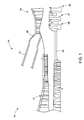
- a remote turbine component replacement apparatus 50 is employed to reach the remote location 42.
- the remote turbine component replacement apparatus 50 is well-suited for manual hand operation by a human user, but it is contemplated that a control system may control and operate the remote turbine component replacement apparatus 50.
- the remote turbine component replacement apparatus 50 is used to reach the remote location 42 from the user accessible region 44.
- An arm 54 that is typically a substantially rigid member extends from a first end 56 to a second end 58. The arm 54 is long enough to result in the first end 56 extending out of the outer casing to the user accessible region 44 when the second end 58 is extended to the aft region 34.
- the first end 56 extends to the user accessible region 44 when the second end 58 of the arm 54 is in contact with the aft mount bracket 36.
- the user is able to remain situated away from the aft region 34 of the transition piece 20, thereby alleviating the need to remove the outer casing to remove the mechanical fastener 40 from the aft mount bracket 36 to facilitate removal of the transition piece 20 from the overall gas turbine engine 10.
- the second end 58 comprises a base portion 60 that is configured to engage the aft mount bracket 36.
- the base portion 60 may be formed of various geometries, but an aft side 62 of the base portion 60 comprises a substantially corresponding geometry to that of the aft mount bracket 36.
- the aft mount bracket 36 includes side walls 64 which may transition from an aft wall 68 with a fillet.
- the aft side 62 fittingly engages a forward face 70 of the aft mount bracket 36 to provide proper overall positioning of the remote turbine component replacement apparatus 50. Proper positioning ensures alignment for multiple operation components of the remote turbine component replacement apparatus 50, as will be described in detail below. Additionally, proper engagement with the side walls 64 reduces the likelihood of twisting of the remote turbine component replacement apparatus 50 during operation.
- the base portion 60 is configured to support and house multiple components.
- a material removal tool 72 is disposed proximate the base portion 60 and includes a centerline that is aligned with the centerline of the mechanical fastener 40 upon proper positioning of the base portion 60, relative to the aft mount bracket 36. Proper positioning and operational monitoring is facilitated by inclusion of a borescope 74 disposed proximate the base portion 60. Although illustrated with a physical cable extending from the borescope 74 toward the first end 56 of the arm 54, a wireless signal may be transmitted from the borescope 74. In either event, a viewing region of the remote location 42 is provided to a user of the remote turbine component replacement apparatus 50. Multiple embodiments of the material removal tool 72 are contemplated and include any material removal techniques known in the art.
- the material removal tool 72 is a 0.625" drill.
- a hydraulic wrench used in conjunction with a pin filled socket may be employed to engage the material to be removed, including washer locking tabs, and imposes a torsional force on the material, thereby shearing material from the component.
- the preceding list of embodiments is merely illustrative and is not limiting. Additionally, a combination of the noted tools may be employed in certain embodiments. Regardless of the precise tool employed, the material removal tool 72 is employed to remove material from a turbine material zone.
- the mechanical fastener 40 is the material to be removed in a destructive manner.
- the material removal tool 72 operates to destroy the mechanical fastener 40 by removing material in a debris generating fashion.
- the material removal tool 72 is controlled by a user situated at the user accessible region 44.
- a tool cable 76 extending toward the first end 56 of the arm 54 is in operative communication with a control accessible to the user.
- the material removal tool 72 removes material from the turbine material zone, such as the mechanical fastener 40, thereby generating debris.
- a debris removal component 78 is disposed proximate, or partially housed within, the base portion 60.
- the debris removal component 78 is a vacuum that transports the debris generated during the removal process from the second end 58 toward the first end 56 of the arm 54.
- a forward support 80 is included to engage the forward region 32 of the transition piece 20.
- the forward support 80 comprises a plurality of apertures 82 configured to slide over combustion cans and any associated liners, to a location proximate the forward region 32 of the transition piece 20.
- the forward support 80 may be formed of a ferromagnetic material that magnetically attracts to the outer surface 38 of the transition piece 20, thereby providing a stabilizing force during operation of the remote turbine component replacement apparatus 50.
- the remote turbine component replacement apparatus 50 is configured to install fastening bolts to secure a turbine component, such as the transition piece 20, to the aft mount bracket 36.
- a first socket 84 (also referred to herein as a material removal socket) is secured to the remote turbine component replacement apparatus 50 proximate the base portion 60 of the arm 54.
- the first socket 84 is removably coupled to the base portion 60.
- the arm 54 is employed to locate of the aft mount bracket 36 to align a bolt 86 and a locking tab washer 87 to a hole 88 of the aft mount bracket 36, via a square drive and the first socket 84.
- the bolt 86 is magnetically engaged with the first socket 84.
- a spring loaded chamfered arm 89 holds the bolt 86 and the locking tab washer 87 in place in the first socket 84 prior to hole engagement. Additionally, magnetic attraction may facilitate retention of the components to the first socket 84.
- the first socket 84 is then rotated to tighten and secure the bolt 86 within the hole 88.
- a second socket 90 (also referred to herein as an installation socket) is also configured to be coupled to the arm 54 proximate the base portion 60 subsequent to removal of the first socket 84.
- the second socket 90 self-aligns, via a scalloped section 92 of the second socket 90, to flats 94 opposite a plurality of tabs 96 of the locking tab washer 87.
- the scalloped section 92 is configured to rotate until their respective flats 98 contact the flats 94.
- An outer sleeve 99 of the second socket 90 threads axially along the scalloped section 92.
- This axial movement causes at least one, but typically a plurality of levers 93 to compress on the plurality of tabs 96 of the locking tab washer 87, thereby properly installing the plurality of tabs 96 to a head portion 95 of the bolt 86.
- the borescope 74 may be employed to visually monitor the bolt installation process.
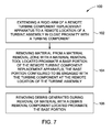
- the method of remotely removing material from a turbine assembly 100 includes extending an arm of a remote turbine component replacement apparatus to a remote location of the turbine assembly in close proximity with a turbine component 102.
- the material is removed from a material removal zone with a material removal tool located proximate a base portion of the remote turbine component replacement apparatus, the base portion configured to be engaged with the turbine component at the remote location of the turbine assembly 104. Debris generated during removal of material is removed with a debris removal component located proximate the base portion 106.
- the method also may include installation of an inspected or new transition piece.
- the first socket 84 and the second socket 90 have been described in detail above.
- the method includes coupling the first socket 84 proximate the base portion 60 and engaging the bolt 86 to the first socket 84, such as with magnetic attraction, for example.
- the bolt 86 is located within the hole 88 and torqued into engagement with the hole 88 to secure the turbine component to the turbine assembly.
- the first socket 84 is removed and the second socket 90 is coupled to the arm 54 proximate the base portion 60.
- the second socket 90 includes an alignment profile that corresponds to a geometry of the head portion 95 of the bolt, thereby facilitating alignment.
- the second socket 90 is rotated to engage a plurality of locking tabs 96 of a locking tab washer 87, with such rotation flattening the plurality of locking tabs 96 upon engagement of the plurality of the locking tabs 96 with at least one lever protruding from the second socket 90, wherein flattening the plurality of locking tabs 96 provides a retention force on the head portion 95 of the bolt 86.
Landscapes
- Engineering & Computer Science (AREA)
- Mechanical Engineering (AREA)
- General Engineering & Computer Science (AREA)
- Chemical & Material Sciences (AREA)
- Combustion & Propulsion (AREA)
- Life Sciences & Earth Sciences (AREA)
- Forests & Forestry (AREA)
- Turbine Rotor Nozzle Sealing (AREA)
- Structures Of Non-Positive Displacement Pumps (AREA)
Applications Claiming Priority (1)
| Application Number | Priority Date | Filing Date | Title |
|---|---|---|---|
| US13/961,339 US20150040394A1 (en) | 2013-08-07 | 2013-08-07 | Remote turbine component replacement apparatus and method of remotely replacing a turbine component |
Publications (2)
| Publication Number | Publication Date |
|---|---|
| EP2835497A2 true EP2835497A2 (fr) | 2015-02-11 |
| EP2835497A3 EP2835497A3 (fr) | 2015-04-15 |
Family
ID=51260723
Family Applications (1)
| Application Number | Title | Priority Date | Filing Date |
|---|---|---|---|
| EP20140179529 Withdrawn EP2835497A3 (fr) | 2013-08-07 | 2014-08-01 | Appareil de remplacement de composant de turbine à distance et procédé de remplacement d'un tel composant |
Country Status (3)
| Country | Link |
|---|---|
| US (1) | US20150040394A1 (fr) |
| EP (1) | EP2835497A3 (fr) |
| JP (1) | JP2015034546A (fr) |
Families Citing this family (2)
| Publication number | Priority date | Publication date | Assignee | Title |
|---|---|---|---|---|
| US10717166B2 (en) | 2016-12-02 | 2020-07-21 | General Electric Company | Motorized apparatus for use with rotary machines |
| US10494926B2 (en) * | 2017-08-28 | 2019-12-03 | General Electric Company | System and method for maintaining machines |
Family Cites Families (37)
| Publication number | Priority date | Publication date | Assignee | Title |
|---|---|---|---|---|
| US4422288A (en) * | 1981-03-02 | 1983-12-27 | General Electric Company | Aft mounting system for combustion transition duct members |
| FR2653361A1 (fr) * | 1989-10-25 | 1991-04-26 | Snecma | Outillage de retouche d'aubes de rotor d'une turbomachine et procede de retouche utilisant cet outillage. |
| IT1237154B (it) * | 1989-12-22 | 1993-05-24 | Black & Decker Italia | Impugnatura con testa aspirante per trapano portatile |
| DE4024022A1 (de) * | 1990-07-28 | 1992-01-30 | Hilti Ag | Bohr- oder meisselgeraet mit absaugvorrichtung |
| US5233744A (en) * | 1991-01-10 | 1993-08-10 | Noland Edmund B | In site flywheel repair apparatus |
| DE4241767C1 (de) * | 1992-12-11 | 1993-12-09 | Wolf Gmbh Richard | Instrument zum Bearbeiten der Oberfläche von Teilen in technischen Hohlräumen |
| US5644394A (en) * | 1994-10-19 | 1997-07-01 | United Technologies Corporation | System for repairing damaged gas turbine engine airfoils |
| JP2877296B2 (ja) * | 1995-09-11 | 1999-03-31 | 三菱重工業株式会社 | ガスタービン燃焼器の取付、取外し装置 |
| US5772367A (en) * | 1996-06-04 | 1998-06-30 | Daniel; Elie C. | Suction/blower attachment for power tools |
| GB9816421D0 (en) * | 1998-07-28 | 1998-09-23 | Keymed Medicals & Ind Equip | Apparatus for delivering laser energy to a remote location |
| JP2000107949A (ja) * | 1998-09-30 | 2000-04-18 | Toshiba Fa Syst Eng Corp | 燃焼器部品供給装置 |
| US6146066A (en) * | 1999-01-14 | 2000-11-14 | Yelton; Edwin C. | Dust collection router |
| DE10115116A1 (de) * | 2001-03-27 | 2002-10-10 | Hilti Ag | Staubabsaugung für ein Handwerkzeuggerät |
| EP1371812A1 (fr) * | 2002-06-04 | 2003-12-17 | ALSTOM (Switzerland) Ltd | Procédé de réparation pour les aubes d'une turbine à gaz |
| US20040076485A1 (en) * | 2002-10-18 | 2004-04-22 | Robert Kraus | Aspirating means for a power hand tool, more particularly a router |
| US7032279B2 (en) * | 2002-10-18 | 2006-04-25 | General Electric Company | Apparatus and methods for repairing compressor airfoils in situ |
| DE10342507A1 (de) * | 2003-09-12 | 2005-04-14 | Hilti Ag | Absaugvorrichtung |
| US7097539B2 (en) * | 2003-11-18 | 2006-08-29 | Dieter Moeller | Rotary grinding apparatus for blending defects on turbine blades and associated method of use |
| US6899593B1 (en) * | 2003-11-18 | 2005-05-31 | Dieter Moeller | Grinding apparatus for blending defects on turbine blades and associated method of use |
| US7285038B1 (en) * | 2004-02-04 | 2007-10-23 | Les Jioia | Sanding attachment for a reciprocating power tool |
| DE102004025747A1 (de) * | 2004-05-26 | 2005-12-22 | Hilti Ag | Staubabsaugvorrichtung |
| ITMI20060815A1 (it) * | 2006-04-24 | 2007-10-25 | Guido Valentini | Contenitore di raccolta polvere con elemento palettato per utensile motorizzato con capacita' di aspirazione |
| US7766726B2 (en) * | 2006-11-16 | 2010-08-03 | General Electric Company | In-situ compressor blade tip cropping assembly and method |
| US20100329816A1 (en) * | 2007-10-31 | 2010-12-30 | Carl Strom | Self-Tapping Insert and Method of Utilizing the Same to Replace Damaged Threads for Hydraulic and Pneumatic Applications |
| US7819613B2 (en) * | 2007-10-31 | 2010-10-26 | Carl Strom | Self-tapping insert and method of utilizing the same to replace damaged bores and threads |
| US7555971B2 (en) * | 2007-12-04 | 2009-07-07 | Michael Sosnowski | Self-contained hydraulically operated tool |
| EP2254728B1 (fr) * | 2008-02-19 | 2019-09-11 | Rolls-Royce Corporation | Système et procédé pour réparer des objets |
| JP5010521B2 (ja) * | 2008-03-28 | 2012-08-29 | 三菱重工業株式会社 | 燃焼器尾筒案内治具及びガスタービンの燃焼器の取り外し方法、並びに製造方法 |
| US8397342B2 (en) * | 2008-12-09 | 2013-03-19 | Credo Technology Corporation | Debris removal system for power tool |
| US8534965B2 (en) * | 2009-04-17 | 2013-09-17 | General Electric Company | Apparatus and tools for use with compressors |
| US8640335B2 (en) * | 2009-08-13 | 2014-02-04 | Alstom Technology Ltd. | Apparatus for broaching repair of turbine rotor steeples |
| US20120224048A1 (en) * | 2011-03-03 | 2012-09-06 | Trzcinski Frank J | Portable boroscope for inspecting turbomachine blades |
| US8713775B2 (en) * | 2011-06-16 | 2014-05-06 | General Electric Company | Apparatus and method for servicing dynamoelectric machine components in-situ |
| US8726502B2 (en) * | 2012-02-08 | 2014-05-20 | General Electric Company | Turbine servicing apparatus and methods |
| US20130232792A1 (en) * | 2012-03-12 | 2013-09-12 | General Electric Company | Apparatus and method for servicing turbomachinery components in-situ |
| US9085060B2 (en) * | 2012-12-21 | 2015-07-21 | General Electric Company | Turbine servicing device |
| US20150118939A1 (en) * | 2013-10-24 | 2015-04-30 | Powerhouse Mechanical Repair, Inc. | Portable grinding apparatus |
-
2013
- 2013-08-07 US US13/961,339 patent/US20150040394A1/en not_active Abandoned
-
2014
- 2014-08-01 JP JP2014157285A patent/JP2015034546A/ja active Pending
- 2014-08-01 EP EP20140179529 patent/EP2835497A3/fr not_active Withdrawn
Non-Patent Citations (1)
| Title |
|---|
| None |
Also Published As
| Publication number | Publication date |
|---|---|
| US20150040394A1 (en) | 2015-02-12 |
| EP2835497A3 (fr) | 2015-04-15 |
| JP2015034546A (ja) | 2015-02-19 |
Similar Documents
| Publication | Publication Date | Title |
|---|---|---|
| CN102794739B (zh) | 用于从燃气轮机壳体移除销的工具 | |
| US8870171B2 (en) | Shroud retaining pin extraction systems and methods | |
| US8782865B2 (en) | Combustor liner and flow sleeve tool | |
| US8776347B2 (en) | Tool for rotor assembly and disassembly | |
| CN112236261B (zh) | 用于修复受损螺纹的方法和工具 | |
| EP2947335B2 (fr) | Outil de vissage | |
| US20090110552A1 (en) | Compressor stator vane repair with pin | |
| TW201738455A (zh) | 可動葉片的拆卸方法,執行該方法所需的拆卸裝置,具備該拆卸裝置的轉子組 | |
| EP2835497A2 (fr) | Appareil de remplacement de composant de turbine à distance et procédé de remplacement d'un tel composant | |
| US20100189548A1 (en) | Rotation arrangement | |
| US9816398B2 (en) | Turbine shroud block removal apparatus | |
| EP2354458A2 (fr) | Ensemble d'entretoisement à verrouillage | |
| HK1222216A1 (zh) | 涡轮泵 | |
| CN101025095A (zh) | 用于进行发动机维修的方法和装置 | |
| KR102756987B1 (ko) | 크로스 파이어 튜브 설치/제거 방법 및 장치 | |
| JP7019426B2 (ja) | 燃焼缶メンテナンス装置および方法 | |
| CN109571367B (zh) | 一种螺桩组件拆卸方法以及螺桩组件拆卸再安装方法 | |
| EP3252322B1 (fr) | Boulon de centrage | |
| CN115705786A (zh) | 叶片挡板模拟装置 | |
| EP3333378A1 (fr) | Anti-rotation d'écrou par l'intermédiaire d'un insert | |
| US20160230599A1 (en) | Flangeless conical sleeve and method of repair | |
| CN211589930U (zh) | 一种电机主轴拆卸工装 | |
| WO2016032515A1 (fr) | Agencement à baïonnette d'un élément carcasse utilisant des crochets inclinés et procédé pour fixer et retirer cet élément |
Legal Events
| Date | Code | Title | Description |
|---|---|---|---|
| PUAI | Public reference made under article 153(3) epc to a published international application that has entered the european phase |
Free format text: ORIGINAL CODE: 0009012 |
|
| 17P | Request for examination filed |
Effective date: 20140801 |
|
| AK | Designated contracting states |
Kind code of ref document: A2 Designated state(s): AL AT BE BG CH CY CZ DE DK EE ES FI FR GB GR HR HU IE IS IT LI LT LU LV MC MK MT NL NO PL PT RO RS SE SI SK SM TR |
|
| AX | Request for extension of the european patent |
Extension state: BA ME |
|
| PUAL | Search report despatched |
Free format text: ORIGINAL CODE: 0009013 |
|
| AK | Designated contracting states |
Kind code of ref document: A3 Designated state(s): AL AT BE BG CH CY CZ DE DK EE ES FI FR GB GR HR HU IE IS IT LI LT LU LV MC MK MT NL NO PL PT RO RS SE SI SK SM TR |
|
| AX | Request for extension of the european patent |
Extension state: BA ME |
|
| RIC1 | Information provided on ipc code assigned before grant |
Ipc: F01D 25/28 20060101ALI20150309BHEP Ipc: F02C 7/20 20060101ALI20150309BHEP Ipc: B25B 13/48 20060101ALI20150309BHEP Ipc: F01D 5/00 20060101AFI20150309BHEP Ipc: B26D 1/00 20060101ALI20150309BHEP Ipc: F01D 25/24 20060101ALI20150309BHEP Ipc: B23P 6/00 20060101ALI20150309BHEP Ipc: B26D 7/18 20060101ALI20150309BHEP |
|
| R17P | Request for examination filed (corrected) |
Effective date: 20151015 |
|
| RBV | Designated contracting states (corrected) |
Designated state(s): AL AT BE BG CH CY CZ DE DK EE ES FI FR GB GR HR HU IE IS IT LI LT LU LV MC MK MT NL NO PL PT RO RS SE SI SK SM TR |
|
| GRAP | Despatch of communication of intention to grant a patent |
Free format text: ORIGINAL CODE: EPIDOSNIGR1 |
|
| INTG | Intention to grant announced |
Effective date: 20180604 |
|
| GRAS | Grant fee paid |
Free format text: ORIGINAL CODE: EPIDOSNIGR3 |
|
| STAA | Information on the status of an ep patent application or granted ep patent |
Free format text: STATUS: THE APPLICATION IS DEEMED TO BE WITHDRAWN |
|
| 18D | Application deemed to be withdrawn |
Effective date: 20181016 |