EP2835501A1 - Composant profilé et motor à turbine à gaz associé - Google Patents
Composant profilé et motor à turbine à gaz associé Download PDFInfo
- Publication number
- EP2835501A1 EP2835501A1 EP14177271.5A EP14177271A EP2835501A1 EP 2835501 A1 EP2835501 A1 EP 2835501A1 EP 14177271 A EP14177271 A EP 14177271A EP 2835501 A1 EP2835501 A1 EP 2835501A1
- Authority
- EP
- European Patent Office
- Prior art keywords
- wall
- suction
- aerofoil
- side outer
- passages
- Prior art date
- Legal status (The legal status is an assumption and is not a legal conclusion. Google has not performed a legal analysis and makes no representation as to the accuracy of the status listed.)
- Granted
Links
Images




Classifications
-
- F—MECHANICAL ENGINEERING; LIGHTING; HEATING; WEAPONS; BLASTING
- F01—MACHINES OR ENGINES IN GENERAL; ENGINE PLANTS IN GENERAL; STEAM ENGINES
- F01D—NON-POSITIVE DISPLACEMENT MACHINES OR ENGINES, e.g. STEAM TURBINES
- F01D5/00—Blades; Blade-carrying members; Heating, heat-insulating, cooling or antivibration means on the blades or the members
- F01D5/12—Blades
- F01D5/14—Form or construction
- F01D5/18—Hollow blades, i.e. blades with cooling or heating channels or cavities; Heating, heat-insulating or cooling means on blades
- F01D5/186—Film cooling
-
- F—MECHANICAL ENGINEERING; LIGHTING; HEATING; WEAPONS; BLASTING
- F01—MACHINES OR ENGINES IN GENERAL; ENGINE PLANTS IN GENERAL; STEAM ENGINES
- F01D—NON-POSITIVE DISPLACEMENT MACHINES OR ENGINES, e.g. STEAM TURBINES
- F01D5/00—Blades; Blade-carrying members; Heating, heat-insulating, cooling or antivibration means on the blades or the members
- F01D5/12—Blades
- F01D5/14—Form or construction
- F01D5/18—Hollow blades, i.e. blades with cooling or heating channels or cavities; Heating, heat-insulating or cooling means on blades
- F01D5/187—Convection cooling
-
- F—MECHANICAL ENGINEERING; LIGHTING; HEATING; WEAPONS; BLASTING
- F01—MACHINES OR ENGINES IN GENERAL; ENGINE PLANTS IN GENERAL; STEAM ENGINES
- F01D—NON-POSITIVE DISPLACEMENT MACHINES OR ENGINES, e.g. STEAM TURBINES
- F01D5/00—Blades; Blade-carrying members; Heating, heat-insulating, cooling or antivibration means on the blades or the members
- F01D5/12—Blades
- F01D5/14—Form or construction
- F01D5/18—Hollow blades, i.e. blades with cooling or heating channels or cavities; Heating, heat-insulating or cooling means on blades
-
- F—MECHANICAL ENGINEERING; LIGHTING; HEATING; WEAPONS; BLASTING
- F05—INDEXING SCHEMES RELATING TO ENGINES OR PUMPS IN VARIOUS SUBCLASSES OF CLASSES F01-F04
- F05D—INDEXING SCHEME FOR ASPECTS RELATING TO NON-POSITIVE-DISPLACEMENT MACHINES OR ENGINES, GAS-TURBINES OR JET-PROPULSION PLANTS
- F05D2260/00—Function
- F05D2260/20—Heat transfer, e.g. cooling
- F05D2260/201—Heat transfer, e.g. cooling by impingement of a fluid
-
- F—MECHANICAL ENGINEERING; LIGHTING; HEATING; WEAPONS; BLASTING
- F05—INDEXING SCHEMES RELATING TO ENGINES OR PUMPS IN VARIOUS SUBCLASSES OF CLASSES F01-F04
- F05D—INDEXING SCHEME FOR ASPECTS RELATING TO NON-POSITIVE-DISPLACEMENT MACHINES OR ENGINES, GAS-TURBINES OR JET-PROPULSION PLANTS
- F05D2260/00—Function
- F05D2260/20—Heat transfer, e.g. cooling
- F05D2260/202—Heat transfer, e.g. cooling by film cooling
-
- F—MECHANICAL ENGINEERING; LIGHTING; HEATING; WEAPONS; BLASTING
- F05—INDEXING SCHEMES RELATING TO ENGINES OR PUMPS IN VARIOUS SUBCLASSES OF CLASSES F01-F04
- F05D—INDEXING SCHEME FOR ASPECTS RELATING TO NON-POSITIVE-DISPLACEMENT MACHINES OR ENGINES, GAS-TURBINES OR JET-PROPULSION PLANTS
- F05D2260/00—Function
- F05D2260/20—Heat transfer, e.g. cooling
- F05D2260/221—Improvement of heat transfer
- F05D2260/2214—Improvement of heat transfer by increasing the heat transfer surface
- F05D2260/22141—Improvement of heat transfer by increasing the heat transfer surface using fins or ribs
Definitions
- the present invention relates to an aerofoil component of a gas turbine engine, and particularly an aerofoil portion which contains one or more passages for the transport of coolant therethrough.
- the high pressure (HP) turbine gas temperatures are now much hotter than the melting point of the blade materials used and in some engine designs the intermediate pressure (IP) and low pressure (LP) turbines are also cooled.
- IP intermediate pressure
- LP low pressure
- Air is conventionally used as a coolant and is flowed in and around the gas-path aerofoils.
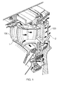
- Fig. 1 shows an isometric view of a typical cooled stage of a gas turbine engine. Cooling air flows are indicated by arrows.
- Fig. 1 shows HP turbine NGVs 1 and HP rotor blades 2. Both the NGVs 1 and HP rotor blades 2 have aerofoil portions 100 which span the working gas annulus of the engine.
- HP turbine NGVs generally consume the greatest amount of cooling air flow in high temperature engines.
- HP rotor blades typically use about half of the NGV cooling air flow.
- the IP and LP stages downstream of the HP turbine use progressively less cooling air flow.
- the HP rotor blades 2 are cooled by using high pressure air from the compressor that has by-passed the combustor and is therefore relatively cool compared to the gas temperature.
- Typical cooling air temperatures are between 800 and 1000 K, while gas temperatures can be in excess of 2100 K.
- the cooling air from the compressor that is used to cool the hot turbine components is not used fully to extract work from the turbine. Extracting coolant flow therefore has an adverse effect on the engine operating efficiency. It is thus important to use this cooling air as effectively as possible.
- Fig. 2 shows a transverse cross-section through an HP turbine rotor blade aerofoil portion 100 with wall cooling around the suction surface S.
- Suction side outer wall 110 and pressure side outer wall 140 define the external pressure side P and suction side S aerofoil surfaces of the aerofoil portion 100.
- Each outer wall 110, 140 extends from a leading edge LE to a trailing edge TE of the aerofoil portion 100.
- the aerofoil portion 100 in Fig. 2 has four main coolant passages 114 that extend in the annulus-spanning direction of the aerofoil portion 100. The front three of these passages are interconnected such that cooling air flows through the passages in series, reversing direction, as indicated by curved block arrows, between passages. The cooling air enters the main passages from feed passages at the root of blade, as indicated by the straight block arrows.
- the aerofoil portion 100 further has a plurality of suction wall passages 106 that also extend in the annulus-spanning direction of the aerofoil portion 100.
- the suction wall passages 106 are bounded on opposing first sides by the suction side outer wall 110 and an inner wall 108 that separates the suction wall passages 106 from the main passages114.
- Each suction wall passage 106 is bounded on opposing second sides by a pair of dividing walls 102 which extend between the suction side outer wall 110 and the inner wall 108.
- Fillets 104 smooth the transitions from the dividing walls 102 to the inner wall 108 and to the suction side outer wall 110.
- coolant can flow in series through the suction wall passages with direction reversal.
- thermo-mechanical structural problems and stress A main cause of the stress results from differential thermal effects between the hot suction side outer wall 110 and the relatively cool inner wall 108, the highest thermal gradients occurring in the dividing walls 102 and fillets 104.
- thermal growth of the hot suction side outer wall 110 is much greater than the cold inner wall 108 during transient throttle push, placing the outer wall 110 into compression and the inner wall 108 into tension.
- major stress concentrations are produced, particularly in the fillets 104.
- the thermal gradients at the dividing walls 102 further increase the overall stress levels.
- the fillet radii of the fillets 104 closest to the suction surface S are initially in compression during take off conditions when the suction side outer wall 110 reaches its maximum temperature.
- the local stress level in these fillets 104 can cause the material of the blade to plastically deform or creep such that when the suction side outer wall 110 cools down the fillets 104 can develop micro cracks in tension.
- cracks may propagate in the walls 102, 108, 110 due to low cycle thermal fatigue of the material.
- the present invention seeks to provide an improved aerofoil component.
- a first aspect of the invention provides an aerofoil component of a gas turbine engine, the component having an aerofoil portion which spans, in use, a working gas annulus of the engine, the aerofoil portion having:
- each suction wall passage and/or the radii of curvature of the fillets can reduce stress concentrations in the fillets and promote the creation of dual vortices of coolant in the suction wall passage for more effective removal of heat from the suction side outer wall.
- a second aspect of the invention provides a gas turbine engine having one or more aerofoil components according to the first aspect.
- a kidney-bowl shape on the transverse cross-sections can be particularly effective for creating the dual vortices.
- the overall length of the inner wall on the transverse cross-sections can be increased. This can enhance the compliance of the inner wall, reducing its constraining effect on the outer wall such that differential thermal effects do not generate such high stress concentrations in the fillets.
- the inner wall may curve into each suction wall passage such that, on the transverse cross-sections, the inner wall forms a protrusion into the suction wall passage, the protrusion turning through at least 90° of arc.
- the inner wall may be thinner than the suction side outer wall. This also helps to increase the compliance of the inner wall.
- the ratio of the thickness of the suction side outer wall to the inner wall may be in the range from 1.4 to 1.6.
- the inner wall may reduce in thickness from locations adjacent the fillets of the respective dividing walls to a central region of the inner wall.
- the minimum thicknesses of the dividing walls may be equal, within ⁇ 25%, to twice the thickness of the suction side outer wall. This can strengthen the dividing walls, and can also have an effect of increasing heat conduction along the dividing walls and into the inner wall, and hence can reduce differential thermal effects between the suction side outer wall and the inner wall.
- the suction side outer wall may have a plurality of effusion holes for passing coolant from the suction wall passages to the suction side aerofoil surface.
- Each suction wall passage may have heat transfer augmentation formations provided by the suction side outer wall and/or the inner wall, the heat transfer augmentation formations causing the coolant flow to separate from and reattach to the respective wall.
- the heat transfer augmentation formations may be trip-strips and/or steps. Rows of trip-strips and/or steps which are oppositely angled (e.g. so that a trip-strip or step from one row and an adjacent trip-strip or step from a different row together form a chevron shape) can be particularly effective.
- the suction wall passages may further have a plurality of pedestals extending across the passage to connect the inner wall to the suction side outer wall.
- the pedestals can promote heat conduction between the suction side outer wall and the inner wall, and promote turbulent mixing of the coolant in the passage.
- the inner wall may further have a plurality of through-holes for producing impingement jets impinging on the suction side outer wall, the impingement jets being formed from coolant passing through the through-holes from the main passages into the suction wall passages.
- the aerofoil portion may further have connecting walls which bound the main passages and extend from the pressure side outer wall to the inner wall, the connecting walls meeting the inner wall only at locations which are directly opposite to where the dividing walls meet the inner wall. In this way, the connecting walls can be prevented from compromising the flexibility of the inner wall.
- the aerofoil component may be a turbine section rotor blade, e.g. a high pressure turbine rotor blade.
- a ducted fan gas turbine engine suitable for incorporating the present invention is generally indicated at 10 and has a principal and rotational axis X-X.
- the engine comprises, in axial flow series, an air intake 11, a propulsive fan 12, an intermediate pressure compressor 13, a high-pressure compressor 14, combustion equipment 15, an HP turbine 16, an IP turbine 17, a LP turbine 18 and a core engine exhaust nozzle 19.
- a nacelle 21 generally surrounds the engine 10 and defines the intake 11, a bypass duct 22 and a bypass exhaust nozzle 23.
- air entering the intake 11 is accelerated by the fan 12 to produce two air flows: a first air flow A into the IP compressor 13 and a second air flow B which passes through the bypass duct 22 to provide propulsive thrust.
- the IP compressor 13 compresses the air flow A directed into it before delivering that air to the HP compressor 14 where further compression takes place.
- the compressed air exhausted from the high-pressure compressor 14 is directed into the combustion equipment 15 where it is mixed with fuel and the mixture combusted.
- the resultant hot combustion products then expand through, and thereby drive the high, intermediate and low-pressure turbines 16, 17, 18 before being exhausted through the nozzle 19 to provide additional propulsive thrust.
- the HP, IP and LP turbines respectively drive the HP and IP compressors 14, 13 and the fan 12 by suitable interconnecting shafts.
- HP turbine aerofoil portions are cooled by using high pressure air from the compressor that has by-passed the combustor and is therefore relatively cool compared to the gas temperature.
- Typical cooling air temperatures are between 800 and 1000 K, while gas temperatures can be in excess of 2100 K.
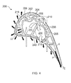
- Figs. 4 shows a transverse cross-sectional view through aerofoil portion 200 of a rotor blade of the HP turbine 16.
- the aerofoil portion 200 has some similarities to the aerofoil portion of Fig. 2 .
- suction side outer wall 210 and pressure side outer wall 240 define the external pressure side P and suction side S aerofoil surfaces of the aerofoil portion 200.
- Each outer wall 210, 240 extends from a leading edge LE to a trailing edge TE of the aerofoil portion 200.
- the aerofoil portion 200 has three main coolant passages 214 that extend in the annulus-spanning direction of the aerofoil portion 200. These passages are interconnected such that cooling air flows through the passages in series, reversing direction, as indicated by curved block arrows, between passages. The cooling air enters the main passages from one or more feed passages at the root of blade, as indicated by the straight block arrows.
- the aerofoil portion 200 also has a plurality of suction wall passages 206 that extend in the annulus-spanning direction of the aerofoil portion 200.
- the suction wall passages 206 are bounded on opposing first sides by the suction side outer wall 210 and an inner wall 208 that separates the suction wall passages 206 from the main passage 214. Cooling air can enter the suction wall passages from the feed passages at the root of blade. As indicated by curved block arrows, the coolant can flow through the suction wall passages in series with direction reversal.
- Each suction wall passage 206 is bounded on opposing second sides by a pair of dividing walls 202 which extend between the suction side outer wall 210 and the inner wall 208.
- one of the pair of dividing walls 202 is closer to the leading edge LE of the aerofoil portion 200 and the other of the pair of the dividing walls 202 is closer to the trailing edge TE.
- Fillets 204 smooth the transitions from the dividing walls 202 to the inner wall 208 and to the suction side outer wall 210.
- the outer walls 210, 240 contain a plurality of effusion holes 216 for the flow of coolant from the interior to the exterior of the aerofoil portion 200.
- the effusion holes 216 in the suction side outer wall 210 allow coolant from the suction wall passages 206 to flow over the suction side aerofoil surface S.
- the fillets 204 are shaped such that on transverse cross-sections to the annulus-spanning direction of the aerofoil 200, the opposing second sides of the suction wall passages 206 can be substantially semi-circular.
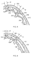
- Fig. 5 shows a close-up view of two of the suction wall passages 206 of the cross-section of Fig. 4 .
- the fillets 204 have radii of curvature R which are large enough to ensure that the two fillets provided by each dividing wall 202 in a given passage 206 merge together to produce a continuously curved surface.
- Fig. 5 shows a close-up view of two of the suction wall passages 206 of the cross-section of Fig. 4 .
- the fillets 204 have radii of curvature R which are large enough to ensure that the two fillets provided by each dividing wall 202 in a given passage 206 merge together to produce a continuously curved surface.
- FIG. 6 shows a close-up view of two of the suction wall passages 106 of the cross-section of Fig. 2 .
- the two fillets 104 provided by each dividing wall 102 in a given passage 106 have smaller radii of curvature r, such that the fillets do not merge together and the dividing wall 102 has a flat surface between the fillets.
- the increased radius of curvature R reduces stress concentrations in the fillets 204, thereby decreasing the amount of plastic deformation or creep that occurs in the fillets when the aerofoil portion 200 is exposed to high thermal gradients.
- the radius of curvature R of the fillets 204 may be equal to the thickness of the suction side outer wall 210, to within ⁇ 25%.
- the substantially semi-circular shape of the opposing second sides of the suction wall passages 206 can also provide benefits in terms of the flow of coolant in the passages.
- dual vortices discussed in more detail below
- the aerofoil portion 200 can have further adaptations to improve its thermo-mechanical performance.
- the inner wall 208 of the aerofoil portion 200 curves into the suction wall passages 206 to give each suction wall passage 206 a kidney-bowl shape on the transverse cross-section, as shown in Figs. 4 and 5 .
- This kidney-bowl shape also helps to promote the creation of dual vortices.
- the curvature of the inner wall 208 which produces the kidney-bowl shapes of the suction wall passages 206 also results in the length of the inner wall 208 on the transverse cross-section being increased relative to the length of the suction side outer wall 210. This length increase in turn increases the compliance or flexibility of the inner wall 208 such that it imposes a reduced constraint on the outer wall 210. In this way, the compressive stress experienced by the outer wall 210 when it undergoes thermal growth can be reduced, and stress concentrations in the fillets 204 can be decreased.
- the inner wall may curve into each suction wall passage such that, on the transverse cross-section, a protrusion into the passage is formed which turns through at least 90° of arc.
- the thicknesses T of the inner wall 108 and of the outer wall 110 are approximately the same (as shown in Fig. 6 ).
- a further adaptation of the aerofoil portion 200 is to reduce the thickness t of the inner wall 208 relative to the thickness T of the outer wall 210 (as shown in Fig. 5 ). This also has the effect of increasing the compliance of the inner wall 208 to better accommodate thermal expansion of the outer wall 210.
- the inner wall 108 and the outer wall 110 are generally formed of the same superalloy (e.g. CMSX-4 single crystal alloy).
- a superalloy e.g. CMSX-4 single crystal alloy.
- a suitable ratio of T/t may thus be in the range from about 1.4 to 1.6 to compensate for the strength difference.
- Another adaptation (not shown in Fig. 5 ) that can increase the compliance of the inner wall 208 is to progressively thin the wall from locations adjacent the fillets 204 to a region at the centre of the wall.
- the wall can thus be thinned at a region distal from the fillets 204, and thus removed from stress concentrations at the fillets.
- connecting walls 218 bound the main passages 214 and link the pressure side outer wall 240 and the inner wall 208.
- the connecting walls 218 may only meet the inner wall 208 at locations directly opposite to where the dividing walls 206 meet the inner wall 208 (i.e. rather than at locations between the dividing walls 206).
- the thickness W of the dividing walls 202 of the aerofoil portion 200 can be increased relative to the thickness w of the dividing walls 102 of the aerofoil portion 100. This can strengthen the dividing walls 202, and can also have an effect of increasing heat conduction (Q in Fig. 5 and q in Fig. 6 , and also indicated by white arrows in Figs. 5 and 6 ) along the dividing walls and into the inner wall, and hence can reduce differential thermal effects between the outer wall 210 and the inner wall 208.
- the minimum thickness W of the dividing walls 202 may be equal, to within ⁇ 25%, to twice the thickness of the suction side outer wall 210.
- Fig. 7 shows modelled thermal gradients present in the suction side outer wall 210, inner wall 208 and dividing walls 202 around the suction wall passages 206. These gradients can be reduced by the provision of trip-strip and/or step heat transfer augmentation formations 222, e.g. on the suction side outer wall 210, as illustrated in Fig. 8 which shows plan views of the surface of the outer wall 210 inside a suction wall passage 206 with different configurations (a) and (b) of trip-strip heat transfer augmentation formations.
- Fig. 8 shows modelled thermal gradients present in the suction side outer wall 210, inner wall 208 and dividing walls 202 around the suction wall passages 206. These gradients can be reduced by the provision of trip-strip and/or step heat transfer augmentation formations 222, e.g. on the suction side outer wall 210, as illustrated in Fig. 8 which shows plan views of the surface of the outer wall 210 inside a suction wall passage 206 with different configurations (
- the trip-strips 222 are in two oppositely angled rows so that adjacent trip-strips from different rows make a chevron shape, the rows extending along the length of the passage.
- the secondary flows 226 encouraged by these trip-strips promote the formation of the dual vortices discussed above, as illustrated by Fig. 9 which shows CFD modelled secondary flows inside a suction wall passage 206 having a chevron arrangement of trip-strips 222.
- Higher levels of heat transfer are developed at the centre of the two rows of trip-strips where the vortex flows converge on the outer wall 210.
- Conversely lower levels of heat transfer are developed at the outer sides of the two rows, for example near the fillet radii 204. Reversing the chevron geometry can produce the opposite effect.
- the kidney-bowl shape of the suction wall passage 206 in combination with the chevron arrangement of the trip strips 222 increases the overall level of heat transfer from the outer wall 210 relative to that from the outer wall 110 of the aerofoil portion 100 shown in Figs. 2 and 6 . This is because the dual vortices increase the suction wall passage 206 flow Reynolds number and corresponding Nusselt number. Additionally, the dual vortices direct the coolant from the cool surface of the inner wall 208 towards the suction side outer wall 210.
- the aerofoil portion 200 may have further cooling arrangements.
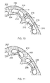
- Fig. 10 shows a cross-sectional view of two suction wall passages 206 in a variant of the HP turbine rotor blade aerofoil of Fig. 4 .
- Impingement jets formed by through-holes 212 in the inner wall 208 impinge coolant on the outer wall 210 as they feed coolant from the main passages 214 into the suction wall passages 206.
- the jets help to increase heat transfer between the suction side outer wall 210 and the coolant.
- Fig. 10 also shows in more detail the effusion holes 216 for the flow of coolant from the suction wall passages 206 to the exterior of the aerofoil portion 200.
- the semi-circular sides of the suction wall passages 206 reduce the risk of back-strike on the inner wall 208 when e.g. a laser or electrical discharge machining (EDM) electrode drills the effusion holes 216.
- EDM electrical discharge machining
- Such back-strike can result in blades being scrapped.
- the increased distance between the two walls 208, 210 at the semi-circular sides improves access for the insertion of a material to absorb or fragment the laser beam, and in relation to EDM, the increased distance allows more time to stop travel of the EDM tool after it breaks through the outer wall 210.
- Fig. 11 shows a cross-sectional view of two suction wall passages 206 in a further variant of the HP turbine rotor blade aerofoil of Fig. 4 .
- Pedestals 220 extend across the passages 206 to connect the inner wall 208 to the suction side outer wall 210.
- the pedestals 220 provide a further conduction path between the hot outer wall 210 and the relatively cool inner wall 208 for the flow of heat q, helping to reduce thermal gradients and better matching the thermal growths of the walls 210, 208.
- the pedestals 220 may also promote turbulent mixing of the coolant in the passages 206. However, they can reduce the flexibility of the inner wall 208.
Landscapes
- Engineering & Computer Science (AREA)
- Mechanical Engineering (AREA)
- General Engineering & Computer Science (AREA)
- Turbine Rotor Nozzle Sealing (AREA)
Applications Claiming Priority (1)
| Application Number | Priority Date | Filing Date | Title |
|---|---|---|---|
| GBGB1314222.9A GB201314222D0 (en) | 2013-08-08 | 2013-08-08 | Aerofoil |
Publications (2)
| Publication Number | Publication Date |
|---|---|
| EP2835501A1 true EP2835501A1 (fr) | 2015-02-11 |
| EP2835501B1 EP2835501B1 (fr) | 2017-09-06 |
Family
ID=49261894
Family Applications (1)
| Application Number | Title | Priority Date | Filing Date |
|---|---|---|---|
| EP14177271.5A Active EP2835501B1 (fr) | 2013-08-08 | 2014-07-16 | Composant profilé et moteur à turbine à gaz associé |
Country Status (3)
| Country | Link |
|---|---|
| US (1) | US9605544B2 (fr) |
| EP (1) | EP2835501B1 (fr) |
| GB (1) | GB201314222D0 (fr) |
Cited By (8)
| Publication number | Priority date | Publication date | Assignee | Title |
|---|---|---|---|---|
| EP3156600A1 (fr) * | 2015-10-15 | 2017-04-19 | General Electric Company | Aube de turbine |
| WO2017074404A1 (fr) * | 2015-10-30 | 2017-05-04 | Siemens Aktiengesellschaft | Profil aérodynamique de turbine avec refroidissement par impact décalé sur le bord de fuite |
| CN107366555A (zh) * | 2016-05-12 | 2017-11-21 | 通用电气公司 | 叶片以及涡轮转子叶片 |
| US10174620B2 (en) | 2015-10-15 | 2019-01-08 | General Electric Company | Turbine blade |
| US10370978B2 (en) | 2015-10-15 | 2019-08-06 | General Electric Company | Turbine blade |
| US10443398B2 (en) | 2015-10-15 | 2019-10-15 | General Electric Company | Turbine blade |
| CN114575931A (zh) * | 2022-03-16 | 2022-06-03 | 中国航发沈阳发动机研究所 | 一种高承温能力涡轮叶片冷却结构 |
| EP4491850A1 (fr) * | 2023-07-04 | 2025-01-15 | Rolls-Royce plc | Composant de moteur à turbine à gaz à géométrie d'orifice de refroidissement variable |
Families Citing this family (10)
| Publication number | Priority date | Publication date | Assignee | Title |
|---|---|---|---|---|
| US10190420B2 (en) * | 2015-02-10 | 2019-01-29 | United Technologies Corporation | Flared crossovers for airfoils |
| US10406596B2 (en) | 2015-05-01 | 2019-09-10 | United Technologies Corporation | Core arrangement for turbine engine component |
| US9850763B2 (en) * | 2015-07-29 | 2017-12-26 | General Electric Company | Article, airfoil component and method for forming article |
| US10227876B2 (en) | 2015-12-07 | 2019-03-12 | General Electric Company | Fillet optimization for turbine airfoil |
| US20170234141A1 (en) * | 2016-02-16 | 2017-08-17 | General Electric Company | Airfoil having crossover holes |
| US10344607B2 (en) * | 2017-01-26 | 2019-07-09 | United Technologies Corporation | Internally cooled engine components |
| CN110462166B (zh) | 2017-04-07 | 2022-12-20 | 通用电气公司 | 用于涡轮组件的冷却组件 |
| US10526898B2 (en) | 2017-10-24 | 2020-01-07 | United Technologies Corporation | Airfoil cooling circuit |
| US11339718B2 (en) | 2018-11-09 | 2022-05-24 | Raytheon Technologies Corporation | Minicore cooling passage network having trip strips |
| US12281595B1 (en) * | 2023-10-13 | 2025-04-22 | Rtx Corporation | Turbine blade with boomerang shaped wall cooling passages |
Citations (4)
| Publication number | Priority date | Publication date | Assignee | Title |
|---|---|---|---|---|
| EP1790819A1 (fr) * | 2005-11-28 | 2007-05-30 | Snecma | Circuit de refroidissement pour aube mobile de turbomachine |
| US7568887B1 (en) * | 2006-11-16 | 2009-08-04 | Florida Turbine Technologies, Inc. | Turbine blade with near wall spiral flow serpentine cooling circuit |
| US20110236221A1 (en) * | 2010-03-26 | 2011-09-29 | Campbell Christian X | Four-Wall Turbine Airfoil with Thermal Strain Control for Reduced Cycle Fatigue |
| WO2013181132A1 (fr) * | 2012-05-31 | 2013-12-05 | General Electric Company | Circuit de refroidissement de profil aérodynamique et profil aérodynamique correspondant |
Family Cites Families (7)
| Publication number | Priority date | Publication date | Assignee | Title |
|---|---|---|---|---|
| GB2283538B (en) * | 1984-12-01 | 1995-09-13 | Rolls Royce | Air cooled gas turbine aerofoil |
| US5667359A (en) * | 1988-08-24 | 1997-09-16 | United Technologies Corp. | Clearance control for the turbine of a gas turbine engine |
| US6036441A (en) | 1998-11-16 | 2000-03-14 | General Electric Company | Series impingement cooled airfoil |
| US7097426B2 (en) | 2004-04-08 | 2006-08-29 | General Electric Company | Cascade impingement cooled airfoil |
| US7377746B2 (en) * | 2005-02-21 | 2008-05-27 | General Electric Company | Airfoil cooling circuits and method |
| US8714926B2 (en) | 2010-09-17 | 2014-05-06 | Siemens Energy, Inc. | Turbine component cooling channel mesh with intersection chambers |
| US9267381B2 (en) * | 2012-09-28 | 2016-02-23 | Honeywell International Inc. | Cooled turbine airfoil structures |
-
2013
- 2013-08-08 GB GBGB1314222.9A patent/GB201314222D0/en not_active Ceased
-
2014
- 2014-07-16 EP EP14177271.5A patent/EP2835501B1/fr active Active
- 2014-07-16 US US14/333,033 patent/US9605544B2/en active Active
Patent Citations (4)
| Publication number | Priority date | Publication date | Assignee | Title |
|---|---|---|---|---|
| EP1790819A1 (fr) * | 2005-11-28 | 2007-05-30 | Snecma | Circuit de refroidissement pour aube mobile de turbomachine |
| US7568887B1 (en) * | 2006-11-16 | 2009-08-04 | Florida Turbine Technologies, Inc. | Turbine blade with near wall spiral flow serpentine cooling circuit |
| US20110236221A1 (en) * | 2010-03-26 | 2011-09-29 | Campbell Christian X | Four-Wall Turbine Airfoil with Thermal Strain Control for Reduced Cycle Fatigue |
| WO2013181132A1 (fr) * | 2012-05-31 | 2013-12-05 | General Electric Company | Circuit de refroidissement de profil aérodynamique et profil aérodynamique correspondant |
Cited By (19)
| Publication number | Priority date | Publication date | Assignee | Title |
|---|---|---|---|---|
| US11401821B2 (en) | 2015-10-15 | 2022-08-02 | General Electric Company | Turbine blade |
| JP2017078418A (ja) * | 2015-10-15 | 2017-04-27 | ゼネラル・エレクトリック・カンパニイ | タービンブレード |
| CN106988788A (zh) * | 2015-10-15 | 2017-07-28 | 通用电气公司 | 涡轮叶片 |
| EP3156600A1 (fr) * | 2015-10-15 | 2017-04-19 | General Electric Company | Aube de turbine |
| US10174620B2 (en) | 2015-10-15 | 2019-01-08 | General Electric Company | Turbine blade |
| US10208605B2 (en) | 2015-10-15 | 2019-02-19 | General Electric Company | Turbine blade |
| CN106988788B (zh) * | 2015-10-15 | 2019-05-03 | 通用电气公司 | 涡轮叶片 |
| US10370978B2 (en) | 2015-10-15 | 2019-08-06 | General Electric Company | Turbine blade |
| US10443398B2 (en) | 2015-10-15 | 2019-10-15 | General Electric Company | Turbine blade |
| US11021969B2 (en) | 2015-10-15 | 2021-06-01 | General Electric Company | Turbine blade |
| WO2017074404A1 (fr) * | 2015-10-30 | 2017-05-04 | Siemens Aktiengesellschaft | Profil aérodynamique de turbine avec refroidissement par impact décalé sur le bord de fuite |
| CN107366555A (zh) * | 2016-05-12 | 2017-11-21 | 通用电气公司 | 叶片以及涡轮转子叶片 |
| CN107366555B (zh) * | 2016-05-12 | 2022-03-08 | 通用电气公司 | 叶片以及涡轮转子叶片 |
| US11199098B2 (en) | 2016-05-12 | 2021-12-14 | General Electric Company | Flared central cavity aft of airfoil leading edge |
| US11732593B2 (en) | 2016-05-12 | 2023-08-22 | General Electric Company | Flared central cavity aft of airfoil leading edge |
| CN114575931A (zh) * | 2022-03-16 | 2022-06-03 | 中国航发沈阳发动机研究所 | 一种高承温能力涡轮叶片冷却结构 |
| CN114575931B (zh) * | 2022-03-16 | 2024-06-07 | 中国航发沈阳发动机研究所 | 一种高承温能力涡轮叶片冷却结构 |
| EP4491850A1 (fr) * | 2023-07-04 | 2025-01-15 | Rolls-Royce plc | Composant de moteur à turbine à gaz à géométrie d'orifice de refroidissement variable |
| US12480407B2 (en) | 2023-07-04 | 2025-11-25 | Rolls-Royce Plc | Gas turbine engine component with variable cooling hole geometry |
Also Published As
| Publication number | Publication date |
|---|---|
| GB201314222D0 (en) | 2013-09-25 |
| EP2835501B1 (fr) | 2017-09-06 |
| US20150044029A1 (en) | 2015-02-12 |
| US9605544B2 (en) | 2017-03-28 |
Similar Documents
| Publication | Publication Date | Title |
|---|---|---|
| EP2835501B1 (fr) | Composant profilé et moteur à turbine à gaz associé | |
| US9518468B2 (en) | Cooled component for the turbine of a gas turbine engine | |
| US7938624B2 (en) | Cooling arrangement for a component of a gas turbine engine | |
| US9206697B2 (en) | Aerofoil cooling | |
| US6428273B1 (en) | Truncated rib turbine nozzle | |
| US9518469B2 (en) | Gas turbine engine component | |
| EP2823151B1 (fr) | Surface portant à socles à canaux de refroidissement internes améliorés | |
| EP3002412B1 (fr) | Refroidissement interne de composants d'une turbine à gaz | |
| EP2746536A1 (fr) | Étage rotorique de turbine | |
| US20120207591A1 (en) | Cooling system having reduced mass pin fins for components in a gas turbine engine | |
| US9512782B2 (en) | Gas turbine engine end-wall component | |
| EP2204545A2 (fr) | Buse comprenant des ouvertures afin de réduire les tensions et moteur à turbine à gaz | |
| EP2634370B1 (fr) | Aube de turbine avec cavité de noyau ayant un virage profilé | |
| US9376918B2 (en) | Aerofoil cooling arrangement | |
| EP3976930A1 (fr) | Aube de turbine à canaux en serpentin | |
| US9200535B2 (en) | Aerofoil blade or vane | |
| US11187085B2 (en) | Turbine bucket with a cooling circuit having an asymmetric root turn | |
| EP3418494B1 (fr) | Commande de flux secondaire | |
| US20170211394A1 (en) | Gas turbine blade with pedestal array | |
| JPS5918203A (ja) | ガスタ−ビンの翼 |
Legal Events
| Date | Code | Title | Description |
|---|---|---|---|
| PUAI | Public reference made under article 153(3) epc to a published international application that has entered the european phase |
Free format text: ORIGINAL CODE: 0009012 |
|
| 17P | Request for examination filed |
Effective date: 20140716 |
|
| AK | Designated contracting states |
Kind code of ref document: A1 Designated state(s): AL AT BE BG CH CY CZ DE DK EE ES FI FR GB GR HR HU IE IS IT LI LT LU LV MC MK MT NL NO PL PT RO RS SE SI SK SM TR |
|
| AX | Request for extension of the european patent |
Extension state: BA ME |
|
| R17P | Request for examination filed (corrected) |
Effective date: 20150611 |
|
| RBV | Designated contracting states (corrected) |
Designated state(s): AL AT BE BG CH CY CZ DE DK EE ES FI FR GB GR HR HU IE IS IT LI LT LU LV MC MK MT NL NO PL PT RO RS SE SI SK SM TR |
|
| RAP1 | Party data changed (applicant data changed or rights of an application transferred) |
Owner name: ROLLS-ROYCE PLC |
|
| 17Q | First examination report despatched |
Effective date: 20160711 |
|
| GRAP | Despatch of communication of intention to grant a patent |
Free format text: ORIGINAL CODE: EPIDOSNIGR1 |
|
| STAA | Information on the status of an ep patent application or granted ep patent |
Free format text: STATUS: GRANT OF PATENT IS INTENDED |
|
| INTG | Intention to grant announced |
Effective date: 20170407 |
|
| GRAS | Grant fee paid |
Free format text: ORIGINAL CODE: EPIDOSNIGR3 |
|
| GRAA | (expected) grant |
Free format text: ORIGINAL CODE: 0009210 |
|
| STAA | Information on the status of an ep patent application or granted ep patent |
Free format text: STATUS: THE PATENT HAS BEEN GRANTED |
|
| AK | Designated contracting states |
Kind code of ref document: B1 Designated state(s): AL AT BE BG CH CY CZ DE DK EE ES FI FR GB GR HR HU IE IS IT LI LT LU LV MC MK MT NL NO PL PT RO RS SE SI SK SM TR |
|
| REG | Reference to a national code |
Ref country code: GB Ref legal event code: FG4D |
|
| REG | Reference to a national code |
Ref country code: CH Ref legal event code: EP Ref country code: AT Ref legal event code: REF Ref document number: 926138 Country of ref document: AT Kind code of ref document: T Effective date: 20170915 |
|
| REG | Reference to a national code |
Ref country code: IE Ref legal event code: FG4D |
|
| REG | Reference to a national code |
Ref country code: DE Ref legal event code: R096 Ref document number: 602014014071 Country of ref document: DE |
|
| REG | Reference to a national code |
Ref country code: NL Ref legal event code: MP Effective date: 20170906 |
|
| REG | Reference to a national code |
Ref country code: LT Ref legal event code: MG4D |
|
| PG25 | Lapsed in a contracting state [announced via postgrant information from national office to epo] |
Ref country code: FI Free format text: LAPSE BECAUSE OF FAILURE TO SUBMIT A TRANSLATION OF THE DESCRIPTION OR TO PAY THE FEE WITHIN THE PRESCRIBED TIME-LIMIT Effective date: 20170906 Ref country code: LT Free format text: LAPSE BECAUSE OF FAILURE TO SUBMIT A TRANSLATION OF THE DESCRIPTION OR TO PAY THE FEE WITHIN THE PRESCRIBED TIME-LIMIT Effective date: 20170906 Ref country code: NO Free format text: LAPSE BECAUSE OF FAILURE TO SUBMIT A TRANSLATION OF THE DESCRIPTION OR TO PAY THE FEE WITHIN THE PRESCRIBED TIME-LIMIT Effective date: 20171206 Ref country code: HR Free format text: LAPSE BECAUSE OF FAILURE TO SUBMIT A TRANSLATION OF THE DESCRIPTION OR TO PAY THE FEE WITHIN THE PRESCRIBED TIME-LIMIT Effective date: 20170906 Ref country code: SE Free format text: LAPSE BECAUSE OF FAILURE TO SUBMIT A TRANSLATION OF THE DESCRIPTION OR TO PAY THE FEE WITHIN THE PRESCRIBED TIME-LIMIT Effective date: 20170906 |
|
| REG | Reference to a national code |
Ref country code: AT Ref legal event code: MK05 Ref document number: 926138 Country of ref document: AT Kind code of ref document: T Effective date: 20170906 |
|
| PG25 | Lapsed in a contracting state [announced via postgrant information from national office to epo] |
Ref country code: LV Free format text: LAPSE BECAUSE OF FAILURE TO SUBMIT A TRANSLATION OF THE DESCRIPTION OR TO PAY THE FEE WITHIN THE PRESCRIBED TIME-LIMIT Effective date: 20170906 Ref country code: BG Free format text: LAPSE BECAUSE OF FAILURE TO SUBMIT A TRANSLATION OF THE DESCRIPTION OR TO PAY THE FEE WITHIN THE PRESCRIBED TIME-LIMIT Effective date: 20171206 Ref country code: GR Free format text: LAPSE BECAUSE OF FAILURE TO SUBMIT A TRANSLATION OF THE DESCRIPTION OR TO PAY THE FEE WITHIN THE PRESCRIBED TIME-LIMIT Effective date: 20171207 Ref country code: ES Free format text: LAPSE BECAUSE OF FAILURE TO SUBMIT A TRANSLATION OF THE DESCRIPTION OR TO PAY THE FEE WITHIN THE PRESCRIBED TIME-LIMIT Effective date: 20170906 Ref country code: RS Free format text: LAPSE BECAUSE OF FAILURE TO SUBMIT A TRANSLATION OF THE DESCRIPTION OR TO PAY THE FEE WITHIN THE PRESCRIBED TIME-LIMIT Effective date: 20170906 |
|
| PG25 | Lapsed in a contracting state [announced via postgrant information from national office to epo] |
Ref country code: NL Free format text: LAPSE BECAUSE OF FAILURE TO SUBMIT A TRANSLATION OF THE DESCRIPTION OR TO PAY THE FEE WITHIN THE PRESCRIBED TIME-LIMIT Effective date: 20170906 |
|
| PG25 | Lapsed in a contracting state [announced via postgrant information from national office to epo] |
Ref country code: RO Free format text: LAPSE BECAUSE OF FAILURE TO SUBMIT A TRANSLATION OF THE DESCRIPTION OR TO PAY THE FEE WITHIN THE PRESCRIBED TIME-LIMIT Effective date: 20170906 Ref country code: PL Free format text: LAPSE BECAUSE OF FAILURE TO SUBMIT A TRANSLATION OF THE DESCRIPTION OR TO PAY THE FEE WITHIN THE PRESCRIBED TIME-LIMIT Effective date: 20170906 Ref country code: CZ Free format text: LAPSE BECAUSE OF FAILURE TO SUBMIT A TRANSLATION OF THE DESCRIPTION OR TO PAY THE FEE WITHIN THE PRESCRIBED TIME-LIMIT Effective date: 20170906 |
|
| PG25 | Lapsed in a contracting state [announced via postgrant information from national office to epo] |
Ref country code: EE Free format text: LAPSE BECAUSE OF FAILURE TO SUBMIT A TRANSLATION OF THE DESCRIPTION OR TO PAY THE FEE WITHIN THE PRESCRIBED TIME-LIMIT Effective date: 20170906 Ref country code: SM Free format text: LAPSE BECAUSE OF FAILURE TO SUBMIT A TRANSLATION OF THE DESCRIPTION OR TO PAY THE FEE WITHIN THE PRESCRIBED TIME-LIMIT Effective date: 20170906 Ref country code: IS Free format text: LAPSE BECAUSE OF FAILURE TO SUBMIT A TRANSLATION OF THE DESCRIPTION OR TO PAY THE FEE WITHIN THE PRESCRIBED TIME-LIMIT Effective date: 20180106 Ref country code: IT Free format text: LAPSE BECAUSE OF FAILURE TO SUBMIT A TRANSLATION OF THE DESCRIPTION OR TO PAY THE FEE WITHIN THE PRESCRIBED TIME-LIMIT Effective date: 20170906 Ref country code: AT Free format text: LAPSE BECAUSE OF FAILURE TO SUBMIT A TRANSLATION OF THE DESCRIPTION OR TO PAY THE FEE WITHIN THE PRESCRIBED TIME-LIMIT Effective date: 20170906 Ref country code: SK Free format text: LAPSE BECAUSE OF FAILURE TO SUBMIT A TRANSLATION OF THE DESCRIPTION OR TO PAY THE FEE WITHIN THE PRESCRIBED TIME-LIMIT Effective date: 20170906 |
|
| REG | Reference to a national code |
Ref country code: DE Ref legal event code: R097 Ref document number: 602014014071 Country of ref document: DE |
|
| PLBE | No opposition filed within time limit |
Free format text: ORIGINAL CODE: 0009261 |
|
| STAA | Information on the status of an ep patent application or granted ep patent |
Free format text: STATUS: NO OPPOSITION FILED WITHIN TIME LIMIT |
|
| REG | Reference to a national code |
Ref country code: FR Ref legal event code: PLFP Year of fee payment: 5 |
|
| PG25 | Lapsed in a contracting state [announced via postgrant information from national office to epo] |
Ref country code: DK Free format text: LAPSE BECAUSE OF FAILURE TO SUBMIT A TRANSLATION OF THE DESCRIPTION OR TO PAY THE FEE WITHIN THE PRESCRIBED TIME-LIMIT Effective date: 20170906 |
|
| 26N | No opposition filed |
Effective date: 20180607 |
|
| PG25 | Lapsed in a contracting state [announced via postgrant information from national office to epo] |
Ref country code: SI Free format text: LAPSE BECAUSE OF FAILURE TO SUBMIT A TRANSLATION OF THE DESCRIPTION OR TO PAY THE FEE WITHIN THE PRESCRIBED TIME-LIMIT Effective date: 20170906 |
|
| REG | Reference to a national code |
Ref country code: CH Ref legal event code: PL |
|
| PG25 | Lapsed in a contracting state [announced via postgrant information from national office to epo] |
Ref country code: MC Free format text: LAPSE BECAUSE OF FAILURE TO SUBMIT A TRANSLATION OF THE DESCRIPTION OR TO PAY THE FEE WITHIN THE PRESCRIBED TIME-LIMIT Effective date: 20170906 Ref country code: LU Free format text: LAPSE BECAUSE OF NON-PAYMENT OF DUE FEES Effective date: 20180716 |
|
| REG | Reference to a national code |
Ref country code: BE Ref legal event code: MM Effective date: 20180731 |
|
| REG | Reference to a national code |
Ref country code: IE Ref legal event code: MM4A |
|
| PG25 | Lapsed in a contracting state [announced via postgrant information from national office to epo] |
Ref country code: IE Free format text: LAPSE BECAUSE OF NON-PAYMENT OF DUE FEES Effective date: 20180716 Ref country code: LI Free format text: LAPSE BECAUSE OF NON-PAYMENT OF DUE FEES Effective date: 20180731 Ref country code: CH Free format text: LAPSE BECAUSE OF NON-PAYMENT OF DUE FEES Effective date: 20180731 |
|
| PG25 | Lapsed in a contracting state [announced via postgrant information from national office to epo] |
Ref country code: BE Free format text: LAPSE BECAUSE OF NON-PAYMENT OF DUE FEES Effective date: 20180731 |
|
| PG25 | Lapsed in a contracting state [announced via postgrant information from national office to epo] |
Ref country code: MT Free format text: LAPSE BECAUSE OF NON-PAYMENT OF DUE FEES Effective date: 20180716 |
|
| PG25 | Lapsed in a contracting state [announced via postgrant information from national office to epo] |
Ref country code: TR Free format text: LAPSE BECAUSE OF FAILURE TO SUBMIT A TRANSLATION OF THE DESCRIPTION OR TO PAY THE FEE WITHIN THE PRESCRIBED TIME-LIMIT Effective date: 20170906 |
|
| PG25 | Lapsed in a contracting state [announced via postgrant information from national office to epo] |
Ref country code: PT Free format text: LAPSE BECAUSE OF FAILURE TO SUBMIT A TRANSLATION OF THE DESCRIPTION OR TO PAY THE FEE WITHIN THE PRESCRIBED TIME-LIMIT Effective date: 20170906 Ref country code: HU Free format text: LAPSE BECAUSE OF FAILURE TO SUBMIT A TRANSLATION OF THE DESCRIPTION OR TO PAY THE FEE WITHIN THE PRESCRIBED TIME-LIMIT; INVALID AB INITIO Effective date: 20140716 |
|
| PG25 | Lapsed in a contracting state [announced via postgrant information from national office to epo] |
Ref country code: MK Free format text: LAPSE BECAUSE OF NON-PAYMENT OF DUE FEES Effective date: 20170906 Ref country code: CY Free format text: LAPSE BECAUSE OF FAILURE TO SUBMIT A TRANSLATION OF THE DESCRIPTION OR TO PAY THE FEE WITHIN THE PRESCRIBED TIME-LIMIT Effective date: 20170906 |
|
| PG25 | Lapsed in a contracting state [announced via postgrant information from national office to epo] |
Ref country code: AL Free format text: LAPSE BECAUSE OF FAILURE TO SUBMIT A TRANSLATION OF THE DESCRIPTION OR TO PAY THE FEE WITHIN THE PRESCRIBED TIME-LIMIT Effective date: 20170906 |
|
| P01 | Opt-out of the competence of the unified patent court (upc) registered |
Effective date: 20230528 |
|
| PGFP | Annual fee paid to national office [announced via postgrant information from national office to epo] |
Ref country code: DE Payment date: 20250728 Year of fee payment: 12 |
|
| PGFP | Annual fee paid to national office [announced via postgrant information from national office to epo] |
Ref country code: GB Payment date: 20250722 Year of fee payment: 12 |
|
| PGFP | Annual fee paid to national office [announced via postgrant information from national office to epo] |
Ref country code: FR Payment date: 20250725 Year of fee payment: 12 |