EP2835539A1 - Verfahren zur herstellung eines zentrifugalgebläses - Google Patents
Verfahren zur herstellung eines zentrifugalgebläses Download PDFInfo
- Publication number
- EP2835539A1 EP2835539A1 EP14771179.0A EP14771179A EP2835539A1 EP 2835539 A1 EP2835539 A1 EP 2835539A1 EP 14771179 A EP14771179 A EP 14771179A EP 2835539 A1 EP2835539 A1 EP 2835539A1
- Authority
- EP
- European Patent Office
- Prior art keywords
- bonding
- forming member
- pressure surface
- surface portion
- shroud
- Prior art date
- Legal status (The legal status is an assumption and is not a legal conclusion. Google has not performed a legal analysis and makes no representation as to the accuracy of the status listed.)
- Granted
Links
Images





Classifications
-
- F—MECHANICAL ENGINEERING; LIGHTING; HEATING; WEAPONS; BLASTING
- F04—POSITIVE - DISPLACEMENT MACHINES FOR LIQUIDS; PUMPS FOR LIQUIDS OR ELASTIC FLUIDS
- F04D—NON-POSITIVE-DISPLACEMENT PUMPS
- F04D29/00—Details, component parts, or accessories
- F04D29/26—Rotors specially for elastic fluids
- F04D29/28—Rotors specially for elastic fluids for centrifugal or helico-centrifugal pumps for radial-flow or helico-centrifugal pumps
- F04D29/30—Vanes
-
- F—MECHANICAL ENGINEERING; LIGHTING; HEATING; WEAPONS; BLASTING
- F04—POSITIVE - DISPLACEMENT MACHINES FOR LIQUIDS; PUMPS FOR LIQUIDS OR ELASTIC FLUIDS
- F04D—NON-POSITIVE-DISPLACEMENT PUMPS
- F04D29/00—Details, component parts, or accessories
- F04D29/26—Rotors specially for elastic fluids
- F04D29/28—Rotors specially for elastic fluids for centrifugal or helico-centrifugal pumps for radial-flow or helico-centrifugal pumps
- F04D29/281—Rotors specially for elastic fluids for centrifugal or helico-centrifugal pumps for radial-flow or helico-centrifugal pumps for fans or blowers
-
- F—MECHANICAL ENGINEERING; LIGHTING; HEATING; WEAPONS; BLASTING
- F04—POSITIVE - DISPLACEMENT MACHINES FOR LIQUIDS; PUMPS FOR LIQUIDS OR ELASTIC FLUIDS
- F04D—NON-POSITIVE-DISPLACEMENT PUMPS
- F04D29/00—Details, component parts, or accessories
- F04D29/60—Mounting; Assembling; Disassembling
- F04D29/62—Mounting; Assembling; Disassembling of radial or helico-centrifugal pumps
- F04D29/624—Mounting; Assembling; Disassembling of radial or helico-centrifugal pumps especially adapted for elastic fluid pumps
Definitions
- the present invention relates to a method of manufacturing a centrifugal fan.
- a centrifugal fan is a fan that accelerates air introduced in an axial direction through a shroud and discharges the air in a radial direction through gaps between blades.
- Such a centrifugal fan may be formed of a synthetic resin or metal.
- a resin centrifugal fan advantageously permits manufacture of blades having various shapes via injection molding, but has poor strength. Therefore, centrifugal fans to be applied to large products are appropriately formed of a metal.
- a metal centrifugal fan is manufactured by cutting a metal sheet in a given shape, bending the metal sheet to define a positive pressure surface portion and a negative pressure surface portion and, thereafter, bonding the positive pressure surface portion and the negative pressure surface portion to each other.
- Japanese Patent Laid-open Publication No. 2000-45997 discloses a blade formed by bending a single metal sheet.
- the blade formed by bending a single metal sheet has an airfoil cross section. More particularly, the blade has a three dimensional shape in which a leading edge 1af of the blade has a prescribed inclination relative to a rotation axis of a centrifugal fan and a trailing edge 1ab of the blade is parallel to the rotation axis.
- respective airfoil cross sections of the blade taken at arbitrary layers perpendicular to the rotation axis have a common camber line.
- a lower edge of the blade bonded to a main plate 3 has the longest camber line and an upper edge of the blade coming into contact with a shroud has the shortest camber line
- the camber line at the upper edge completely overlaps the camber line at the lower edge.
- the blade having the above-described shape is an inevitable consequence of bending a single metal sheet using a mold 5c2 that defines a single camber line as exemplarily shown in (a) of FIG. 7 included in the above patent.
- the blade has a limit in terms of shape, thus having difficulty in having a complicated three dimensional shape, such as, for example, a shape in which a camber line of an airfoil taken at an upper cross section of the blade and a camber line of an airfoil taken at a lower cross section of the blade cross each other, in other words, a twisted shape in a rotation axis.
- a method of manufacturing a centrifugal fan including the steps of: (a) cutting a metal sheet to form a positive pressure surface forming member and a negative pressure surface forming member respectively configuring a positive pressure surface and a negative pressure surface; (b) pressing the positive pressure surface forming member and the negative pressure surface forming member to form a first curved surface portion configuring the positive pressure surface and a second curved surface portion configuring the negative pressure surface; (c) trimming the positive pressure surface forming member provided with the first curved surface portion and the negative pressure surface forming member provided with the second curved surface portion to form a shroud bonding surface portion and a main plate bonding surface portion; (d) bending the shroud bonding surface portion and the main plate bonding surface portion; (e) bonding the positive pressure surface forming member and the negative pressure surface forming member to each other; and (f) bonding the shroud bonding surface portion and a shrou
- the first curved surface portion and the second curved surface portion may define different shapes of curved surfaces.
- trimming may be implemented such that an upper edge and a lower edge of each of the positive pressure surface forming member and the negative pressure surface forming member are bent independently of a front edge of each forming member in the step (d).
- the step (e) may include bonding front edges of the respective forming members to each other and bonding rear edges of the respective forming members to each other. At least one of bonding between the front edges of the respective forming members and bonding between the rear edges of respective forming members may be implemented by resistance welding.
- the resistance welding may be implemented at a plurality of positions aligned in a line from the shroud to the main plate in a state in which the front edges or the rear edges of the respective forming members come into contact with each other.
- the resistance welding may be spot welding.
- the resistance welding may be projection welding, and the method further include the step of forming protrusions at any one of the positive pressure surface forming member and the negative pressure surface forming member so as to protrude toward the other one.
- the protrusion forming step may include forming the protrusions at a plurality of positions, aligned in a line from the shroud to the main plate, on at least one of the front edge and the rear edge of any one of the positive pressure surface forming member and the negative pressure surface forming member.
- the step (e) may include simultaneously melting the protrusions.
- the method may further include the step of processing a rivet hole in at least one of the shroud bonding surface portion and the main plate bonding surface portion, and the step (f) may include fastening a rivet through the rivet hole to couple at least one of the shroud bonding surface portion and the main plate bonding surface portion to the shroud or the main plate.
- the step (f) may include bonding each of the shroud bonding surface portion and the main plate bonding surface portion to the shroud or the main plate in a fastened state of the rivet. Bonding between the shroud bonding surface portion and the shroud or bonding between the main plate bonding surface portion and the main plate may be implemented by resistance welding.
- the resistance welding may be spot welding implemented at a plurality of positions aligned in a line from the front edge to the rear edge of each forming member.
- the method may further include the step of repeatedly implementing the step (b) after the step (d).
- a method of manufacturing a centrifugal fan has the effects of achieving higher rigidity than that of a conventional centrifugal fan formed of a resin material and of enhancing performance of the fan owing to a three dimensional shape of blades.
- the present invention has the effect of enabling formation of a blade having a complicated three dimensional shape that has not been easily achieved in the related art.
- the blade comprised of the two sheets moreover, has the effect of achieving less material cost, higher efficiency of the fan owing to weight reduction and reduced power consumption than in the related art.
- the members since two members are first processed as curved members respectively and then bonded to each other to construct a blade, the members have independent shapes of curved surfaces, which has the effect of enabling formation of a blade having a complicated three dimensional shape (for example, a positive pressure surface and a negative pressure surface of the blade are curved surfaces having different curvature variations).
- the metal blade having a complicated shape has the effect of reducing flow resistance and enhancing performance of the fan, more particularly, efficiency of the fan.
- the present invention has the effect of easily coupling the blade having a three dimensional surface to a shroud or a main plate.
- welding beads between members may be minimized, which has the effect of restricting increase in flow resistance and minimizing a negative effect on balancing of the fan due to the welding beads.
- the present invention has the effect of achieving increased strength and reduced ductility due to characteristics of plastic working.
- FIG 1 is a view showing one example of a plug fan module usable with a centrifugal fan.
- the centrifugal fan according to the embodiments that will be described hereinafter may be applied to refrigerators, air conditioners, cleaners and the like.
- the centrifugal fan may be installed without a duct because it provides natural introduction and discharge of air into and from a fan.
- the centrifugal fan may be applied to a plug fan module for use in an air conditioner which is installed at an outdoor place as exemplarily shown in FIG. 1 and serves to cool or heat air directed from an indoor space and then resupply the air into the indoor space.
- the fan module 1 as described above includes a motor 2 having a rotating shaft, a support frame 3 supporting the motor 2 and a centrifugal fan 4 coupled to the rotating shaft of the motor 2.
- a front panel 5 coupled to a front surface of the support frame 3 has an opening through which air can be introduced into the centrifugal fan 4. The air introduced in a longitudinal direction of the rotating shaft through the opening is discharged in a radial direction from a rear region of the front panel 5 as the centrifugal fan 4 is rotated.
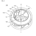
- FIG. 2 is a perspective view showing a centrifugal fan according to one embodiment of the present invention.
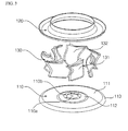
- FIG. 3 is an exploded perspective view of the centrifugal fan shown in FIG. 2 .
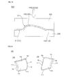
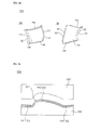
- FIG. 4 is a view showing positions of layers marked at the blade in (a) and cross sections of the blade taken at the layers in (b).
- FIG. 5 is a view showing the cross sections of FIG. 4 projected onto a single plane in a direction of a rotation axis.
- FIG. 6 is a longitudinal sectional view of the blade.
- the centrifugal fan 100 includes a main plate 110, a shroud 120 and a plurality of blades 130.
- the main plate 110, the shroud 120 and the blades 130 may be formed of a metal having plasticity, preferably, steel.
- the main plate 110 is rotated about a rotation axis O by a motor (4, see FIG. 1 ).
- the centrifugal fan 100 may further include a hub 160 configured to couple the main plate 110 and the rotating shaft of the motor to each other.
- the shroud 120 is spaced apart from the main plate 110 and has a suction opening 121 through which air is introduced in a direction of the rotation axis O.
- the shroud 120 takes the form of a ring centrally defining the suction opening 121.
- a diameter of the shroud 120 is gradually increased in a radial direction from an inner circumference of the shroud 120 defining the suction opening 121 and has the maximum value at an outer circumference of the shroud from which an air stream pumped by the blades 130 is discharged.
- the shroud 120 may have a curved inner surface along which air is guided, the curved inner surface of the shroud being convex toward the main plate 110.
- the plural blades 130 are arranged in a circumferential direction between the main plate 110 and the shroud 120. Air suctioned through the suction opening 121 of the shroud 120 is moved from a front edge to a rear edge of the respective blades 130 to thereby be discharged outward.
- the centrifugal fan 100 may include seven blades 130 although this is not essential.
- the main plate 110 may include a blade support plate portion 111 supporting lower edges of the blades 130 and a center hub mounting portion 112 raised from the blade support plate portion 111 toward the shroud 120.
- the hub mounting portion 112 extending from the blade support plate portion 111 is curved by a prescribed curvature.
- the hub mounting portion 112 is centrally provided with a mounting opening 110a for installation of the hub (not shown) to be coupled to the rotating shaft of the motor and a plurality of first fastening holes 110b arranged at a constant interval in a circumferential direction around the mounting opening 110a.
- fastening members such as screws, bolts or the like, are fastened through the first fastening holes 110b, the hub may be fixed.
- a portion of the blade 130 at which an air stream suctioned through the shroud 120 begins to come into contact with the blade 130 is referred to as a front edge FE and a portion of the blade 130 at which the air stream is separated from the blade 130 is referred to as a rear edge RE.
- a front edge FE a portion of the blade 130 at which an air stream suctioned through the shroud 120 begins to come into contact with the blade 130
- a rear edge RE a portion of the blade 130 at which the air stream is separated from the blade 130.
- cross sections of the blade 130 taken at the respective layers have front edges FE located on a prescribed common inner circumference and rear edges RE located on a prescribed common outer circumference, the common outer circumference having a greater diameter than that of the common inner circumference.
- the front edge FE of the blade 130 is located in front of the rear edge RE in a facing direction of the positive pressure surface 131 (or in a rotation direction of the centrifugal fan 100).
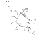
- the blade 130 includes a positive pressure surface forming member 140 that forms the positive pressure surface (131, see FIG. 2 ) and a negative pressure surface forming member 150 that forms the negative pressure surface (132 see FIG. 2 ).
- the positive pressure surface forming member 140 and the negative pressure surface forming member 150 may be coupled to each other with a space S therebetween.
- the entire region of the positive pressure surface 131 is defined by the positive pressure surface forming member 140 and the entire region of the negative pressure surface 132 is defined by the negative pressure surface forming member 150.
- the positive pressure surface forming member 140 and the negative pressure surface forming member 150 may be formed by processing a metal sheet.
- the positive pressure surface forming member 140 (or the negative pressure surface forming member 150) is formed by processing a metal sheet having an even thickness.
- the positive pressure surface forming member 140 or the negative pressure surface forming member 150 may achieve sufficient rigidity with a thickness of approximately 1 mm that is half or more of a conventional blade formed of a metal sheet having a thickness of 2 mm or more.
- the positive pressure surface forming member 140 and the negative pressure surface forming member 150 may be fabricated by pressing a metal sheet having plasticity. More particularly, a steel sheet has high plasticity and is easily formed in various shapes and may achieve sufficient corrosion resistance, heat resistance, rigidity and the like according to the content ratio of carbon (C), chrome (Cr), Nickel (Ni) and the like.
- a steel centrifugal fan may achieve enhanced rigidity and thus is rotatable at a higher rpm than a conventional resin centrifugal fan. The conventional resin centrifugal fan ensures easy formation of a blade having a complicated shape, but has low rigidity.
- the fan when the resin centrifugal fan is applied to a large product, the fan may be problematic in terms of stability because of a high risk of damage to blades due to high external static pressure.
- the blade is constructed using the two metal members 140 and 150, it is possible to achieve sufficient rigidity and to provide the blade with a complicated shape for enhancement in the performance of the fan.
- the positive pressure surface forming member 140 and the negative pressure surface forming member 150 may be bonded to each other at the front edge and the rear edge of the blade 130. Bonding between the positive pressure surface forming member 140 and the negative pressure surface forming member 150 may be implemented at rear surfaces of the respective members.
- a portion of the front edge of the blade 130 where bonding between the positive pressure surface forming member 140 and the negative pressure surface forming member 150 is implemented is referred to as a front edge bonding portion 133 and a portion of the rear edge of the blade 130 where bonding between the positive pressure surface forming member 140 and the negative pressure surface forming member 150 is implemented is referred to as a rear edge bonding portion 134.
- the blade 130 has a main body portion 135 between the front edge bonding portion 133 and the rear edge bonding portion 134 and the main body portion 135 inwardly defines a space S.
- the main body portion 135 may have an enclosed cross section surrounding the space S.
- the positive pressure surface forming member 140 is provided at a front edge thereof with a first front edge bonding surface portion 141 and at a rear edge thereof with a first rear edge bonding surface portion 142.
- the positive pressure surface forming member is further provided with a first curved surface portion 145 between the first front edge bonding surface portion 141 and the second rear edge bonding surface portion 142.
- the negative pressure surface forming member 150 is provided at a front edge thereof with a second front edge bonding surface portion 151 and at a rear edge thereof with a second rear edge bonding surface portion 152.
- the negative pressure surface forming member 150 is further provided with a second curved surface portion 155 between the second front edge bonding surface portion 151 and the second rear edge bonding surface portion 152.
- Bonding between the first front edge bonding surface portion 141 and the second front edge bonding surface portion 151 is implemented at the front edge bonding portion 133 of the blade 130 and bonding between the first rear edge bonding surface portion 142 and the second rear edge bonding surface portion 152 is implemented at the rear edge bonding portion 134.
- a rear surface of the first front edge bonding surface portion 141 (hereinafter referred to as a first front edge bonding surface) and a rear surface of the second front edge bonding surface portion 151 (hereinafter referred to as a second front edge bonding surface) may come into surface contact with each other.
- the first front edge bonding surface portion 141 and the second front edge bonding surface portion 151 may include bonding surfaces having a corresponding shape. That is, the first front edge bonding surface and the second front edge bonding surface may have substantially the same shape so as to be bonded to each other in close contact.
- first rear edge bonding surface portion 142 (hereinafter referred to as a first rear edge bonding surface) and a rear surface of the second rear edge bonding surface portion 152 (hereinafter referred to as a second rear edge bonding surface) may come into surface contact with each other.
- the first rear edge bonding surface portion 142 and the second rear edge bonding surface portion 152 may include bonding surfaces having a corresponding shape. That is, the first rear edge bonding surface and the second rear edge bonding surface may have substantially the same shape so as to be bonded to each other in close contact.
- the main body portion 135 includes the first curved surface portion 145 and the second curved surface portion 155 and the space S is defined between the first curved surface portion 145 and the second curved surface portion 155.
- the space S has a transverse cross sectional shape defined by a rear surface of the first curved surface portion 145 and a rear surface of the second curved surface portion 155 and the top and bottom of the space is respectively defined by the shroud 120 and the main plate 110.
- the positive pressure surface forming member 140 and the negative pressure surface forming member 150 are independent of each other until they are bonded to each other and, therefore, may be freely processed into different shapes. Accordingly, the first curved surface portion 145 and the second curved surface portion 155 may be shaped to exhibit different curvature variations.
- the shapes of the first curved surface portion 145 and the second curved surface portion 155 determine a shape of the positive pressure surface 131 and a shape of the negative pressure surface 132 respectively, the fact that the shapes of the curved surface portions 145 and 155 are freely determined is very advantageous in terms of enhancement in the performance of the fan.
- Bonding between the positive pressure surface forming member 140 and the negative pressure surface forming member 150 at the front edge bonding portion 133 or at the rear edge bonding portion 134 may be implemented by welding, more particularly, resistance welding or laser welding.
- Resistance welding is welding that confines generation of resistance heat to a relative small specific portion by applying pressure to a welding position of a base metal and thereafter passing current therethrough.
- An example of resistance welding may include spot welding or projection welding. Although welding using a welding rod leaves a strip of corrugated fusion beads caused by melting a base metal and the welding rod, projection welding or spot welding has less formation of beads, thus having a less effect on balancing of the fan.
- Laser welding exhibits considerably low heat input to a weld and a narrow heat influence range and leaves behind substantially no welding beads, although it requires relatively great cost and, therefore, enables very precise bonding between members.
- areas of the front edge bonding portion 133 and the rear edge bonding portion 134 may be remarkably reduced.
- the blade 130 may include a shroud connection portion 136 connected to the shroud 120.
- the shroud connection portion 136 may include a shroud bonding surface portion 143 and/or a shroud bonding surface portion 153 bent from an upper edge of at least one of the positive pressure surface forming member 140 and the negative pressure surface forming member 150.
- the positive pressure surface forming member 140 and the negative pressure surface forming member 150 are respectively provided with the first shroud bonding surface portion 143 and the second shroud bonding surface portion 153.
- the first shroud bonding surface portion 143 and the second shroud bonding surface portion 153 are bent in opposite directions.
- the first shroud bonding surface portion 143 and the second shroud bonding surface portion 153 may be bonded to an inner circumferential surface of the shroud 120 by welding.
- Bonding surfaces of the first shroud bonding surface portion 143 and the second shroud bonding surface portion 153 to be bonded to the shroud 120 are preferably curved to correspond to the shape of the inner circumferential surface of the shroud 120 so as to come into close contact with the inner circumferential surface.
- the blade 130 may include a main plate connection portion 137 connected to the main plate 110.
- the main plate connection portion 137 may include a main plate bonding surface portion 144 and/or a main plate bonding surface portion 154 bent from a lower edge of at least one of the positive pressure surface forming member 140 and the negative pressure surface forming member 150.
- the positive pressure surface forming member 140 and the negative pressure surface forming member 150 are respectively provided with the first main plate bonding surface portion 144 and the second main plate bonding surface portion 154.
- the first main plate bonding surface portion 144 and the second main plate bonding surface portion 154 are bent in opposite directions.
- the first main plate bonding surface portion 144 and the second main plate bonding surface portion 154 may be bonded to the main plate 110 by welding.
- Bonding surfaces of the first main plate bonding surface portion 144 and the second main plate bonding surface portion 154 to be bonded to the main plate 110 come into close contact with the main plate 110.
- Bonding between the shroud bonding surface portions 143 and 153 and the shroud 120 or bonding between the main plate bonding surface portions 144 and 154 and the main plate 110 may be implemented by welding, more particularly resistance welding or laser welding. Resistance welding and laser welding have been described above and thus a further description thereof will be omitted hereinafter.
- the blade 130 may have a three dimensional (3D) shape.
- the 3D shape of the blade is defined as a shape in which, when cross sections of the blade taken at prescribed layers corresponding to prescribed planes perpendicular to the rotation axis O are projected onto a prescribed projection plane in a direction of the rotation axis O, two or more lines among lines interconnecting the front edges FE and the rear edges RE of the respective cross sections in the projection plane are not the same line (or do not overlap each other).
- the lines interconnecting the front edges and the rear edges are defined according to given rules.
- the lines may be straight lines interconnecting the front edges FE and the rear edges RE.
- the lines may be lines connecting equidistant points from the positive pressure surface 131 and the negative pressure surface 132.
- a cross section of the blade may have an airfoil shape.
- the main body portion 135 defines an airfoil.
- the entire cross section of an inner circumferential surface of the blade defining the space S has an airfoil shape, but a front edge of the cross section may have a cusp due to bonding between the positive pressure surface forming member 140 and the negative pressure surface forming member 150. Therefore, "airfoil” is defined based on the shape of an outer circumferential surface of the blade 130 and a leading edge LE is defined as being located on a virtual curve that interconnects an outer circumferential surface of the positive pressure surface forming member 140 and an outer circumferential surface of the negative pressure surface forming member 150.
- "r” designates a radius of curvature at the leading edge LE and a radius of curvature at an upper surface or a lower surface of the airfoil has the minimum value at the leading edge LE.
- the main body portion 135 may have an airfoil or streamlined shape inwardly defining the space S.
- airfoil According to the definition proposed by the National Advisory Committee for Aeronautics (NACA) "airfoil" is configured by a leading edge, a trailing edge and an upper surface 145a and a lower surface 155a which connect the leading edge and the trailing edge to each other and a shape of the airfoil is determined by various factors.
- NACA National Advisory Committee for Aeronautics
- chord line CRL that is a straight line connecting the leading edge and the trailing edge to each other
- camber line CBL that is acquired by connecting equidistant points from the upper surface and the lower surface between the leading edge and the trailing edge.
- FIG. 4 four layers perpendicular to the rotation axis O are shown.
- Cross sections S(L1), S(L2), S(L3) and S(L4) of the blade 130 are respectively taken at a first layer Layer 1, a second layer Layer 2, a third layer Layer 3 and a fourth layer Layer 4.
- the first layer Layer 1, the second layer Layer 2, the third layer Layer 3 and the fourth layer Layer 4, which are required to define the shape of the blade 130, may be freely selected so long as they are taken from the top to the bottom along the rotation axis O in this sequence.
- the entire blade 130 acquires a twisted shape in a vertical direction via interrelation between the first cross section S(L1) and the fourth cross section S(L4).
- a cross section of the blade near a shroud and a cross section of the blade near a main plate have substantially the same shape and, thus, the centrifugal fan could not effectively deal with variation of airflow from the shroud to the main plate.
- the centrifugal fan 100 of the present invention may be designed in such a manner that the first cross section S(L1) taken at the first layer Layer 1 is suitable for flow characteristics at the shroud 120 and the fourth cross section S(L4) taken at the fourth layer Layer 4 is suitable for flow characteristics at the main plate 110 independently of the first cross section S(L1). This has the effect of remarkably improving performance, more particularly, efficiency of the fan as compared to the related art.
- a front edge FE(L1) of the first cross section S(L1) close to the shroud 120 may be farther from the rotation axis O than a front edge FE(L4) of the fourth cross section S(L4) close to the main plate 110 and a rear edge RE(L4) of the fourth cross section S(L4) may be farther from the rotation axis O than a rear edge RE(L1) of the first cross section S(L1).
- chord lines of the first cross section S(L1) and the fourth cross section S(L4) cross each other.
- the chord line of the first cross section S(L1) crosses chord lines of a second cross section S(L2) and a third cross section S(L3) as well as the chord line of the fourth cross section S(L4).
- the front edge FE or the rear edge RE of the blade 130 has a prescribed inclination angle with respect to the rotation axis O and, more particularly, an upper edge of the blade close to the shroud 120 is located farther from the rotation axis O than a lower edge of the blade close to the main plate 110. Since air velocity is increased with decreasing distance to the shroud 120, a portion of the blade 130 closer to the shroud 120 must generate greater force.
- At least a portion of the blade 130 is shaped such that a cross section of the blade 130 taken at a layer closer to the shroud 120 is located farther from the rotation axis O and this shape increases a linear velocity of the blade 130 at a layer close to the shroud 120, which allows a corresponding portion of the blade 130 to generate greater force.
- the first layer Layer 1 being described by way of example
- flow inertia is great at the first layer Layer 1 and this may cause flow separation at the rear edge of the cross section of the blade taken at the first layer.
- the blade 130 according to the present embodiment is configured in such a manner that the front edge FE(S1) of the first cross section S(L1) becomes farther from the rotation axis O than in the related art, which increases a flow path from the suction opening 121 of the shroud 120 to the rear edge RE(L4) of the first cross section S(L1) beyond that in the related art, thereby causing air to overcome flow inertia and be smoothly guided to the rear edge RE(L4).
- This has the effect of more efficiently restricting flow separation at the rear edge RE of the blade 130.
- the blade 130 may be configured in such a manner that the first cross section S(L1) is located ahead of the fourth cross section S(L4) in a direction opposite to a rotation direction of the main plate 110. More particularly, at least a portion of the rear edge RE of the blade 130 is more deviated in a direction opposite to a rotation direction of the main plate 110 at an upper edge thereof close to the shroud 120 than at a lower edge thereof close to the main plate 110.
- the rear edge RE(L1) of the first cross section S(L1) is located ahead of the rear edge RE(L4) of the fourth cross section S(L4) in a direction opposite to the rotation direction of the main plate 110. Therefore, the rear edge RE(L1) of the first cross section S(L1) is located closer to the rotation axis O than the front edge FE(L1). This has the effect of substantially restricting increase in a blowing diameter of the blade 130 (i.e.
- the rear edge RE(L1) of the first cross section is located ahead of the rear edge RE(L4) of the fourth cross section in a direction opposite to the rotation direction of the main plate 110 and the rear edge RE(L1) of the first cross section among the rear edges RE(L1), RE(L2), RE(L3) and RE(L4) of the respective cross sections is located at the foremost position in a direction opposite to the rotation direction of the main plate 110.
- This tendency may be equally applied to the front edge FE of the blade 130 and, more particularly, the front edge FE(L1) of the first cross section among the front edges FE(L1), FE(L2), FE(L3) and FE(L4) of the respective cross sections of the blade 130 may be located at the foremost position in a direction opposite to the rotation direction of the main plate 110.
- the front edge FE(L3) of the third cross section may be located ahead of the front edge FE(L4) of the fourth cross section in the rotation direction of the main plate 110.
- This tendency may be equally applied to the rear edge RE.
- the rear edge RE(L3) of the third cross section of the blade 130 may be located ahead of the rear edge RE(L4) of the fourth cross section in the rotation direction of the main plate 110.
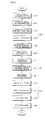
- FIG. 7 is a flowchart showing a method of a manufacturing a centrifugal fan according to one embodiment of the present invention.
- FIG. 8 is a flowchart showing a method of a manufacturing a centrifugal fan according to another embodiment of the present invention.
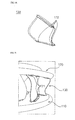
- FIGS. 9A to 9I are views showing the manufacture sequence of the centrifugal fan according to the embodiments of the present invention.
- the method of manufacturing a centrifugal fan according to the present invention includes (a) cutting a metal sheet to form a positive pressure surface forming member and a negative pressure surface forming member which respectively configure a positive pressure surface and a negative pressure surface; (b) pressing the positive pressure surface forming member and the negative pressure surface forming member to form a first curved surface portion configuring the positive pressure surface and a second curved surface portion configuring the negative pressure surface; (c) trimming the positive pressure surface forming member provided with the first curved surface portion and the negative pressure surface forming member provided with the second curved surface portion to form a shroud bonding surface portion and a main plate bonding surface portion; (d) bending the shroud bonding surface portion and the main plate bonding surface portion; (e) bonding the positive pressure surface forming member and the negative pressure surface forming member to each other; and (f) bonding the shroud bonding surface portion to a shroud and bonding the main plate bonding surface portion to a main plate in a bonded state of the positive
- the centrifugal fan 100 may be manufactured by the following steps.
- Protrusions 141a may be formed at a plurality of points, aligned in a line from the shroud 120 to the main plate 110, at the front edge bonding surface portion 141 or 151 or the rear edge bonding surface portion 142 or 152.
- FIG 9F shows that the protrusions 141a are formed in a vertical direction along the front edge bonding surface portion 141 of the positive pressure surface forming member 140, the present invention is not limited thereto and the protrusions 141a may be further formed at the rear edge bonding surface portion 142. Likewise, protrusions may be further formed at the negative pressure surface forming member 150.
- Step S50 formation of the protrusions 141a is implemented after Step S50 by way of example, the present invention is not limited thereto and Step A1 may be implemented at an appropriate point in time before Step S60.
- the projection welding of Step S61 may include simultaneously melting the plural protrusions 141 a.
- current may be applied to the plural protrusions 141a using a single electrode, or current may be simultaneously applied to the respective protrusions 141a using a plurality of electrodes. This has the effect of shortening a bonding process.
- Step S60 as another example of resistance welding, spot welding may be implemented.
- spot welding may be implemented at a plurality of points aligned in a line from the shroud 120 to the main plate 110 at the front edge bonding surface portion 141 or 151 or the rear edge bonding surface portion 142 or 152.
- Resistance welding such as spot welding or projection welding, as exemplarily shown in FIG 6 , causes only a limited portion of a base material coming into contact with an electrode to be molten. Therefore, marks caused when the molten base material is solidified, that is, nuggets 133a are formed at a constant interval on the bonding portions 133 and 134. These nuggets 133a may be arranged in a vertical direction on the bonding portions 133 and 134.
- Step S70 may include a blade positioning step S71, a blade provisional assembly step S72 and a resistance welding step S73.
- the blade 130 is positioned at a predetermined assembly position on the main plate 110.
- the blade 130 is provisionally assembled using fastening members, such as bolts, screws, rivets or the like.
- fastening members such as bolts, screws, rivets or the like.
- processing holes 172 for insertion of the rivets in at least one of the positive pressure surface forming member 140 and the negative pressure surface forming member 150 may be further implemented.
- the shroud 120 and the shroud bonding surface portions 143 and 153 may be fastened to each other and, likewise, the main plate 110 and the main plate bonding surface portions 144 and 154 may be fastened to each other.
- Processing positions of the holes 172 may include at least two positions of a front end and a rear end of the main plate bonding surface portion 144 or 154 and at least one position of a rear end of the shroud bonding surface portion 143 or 153.
- the hole 172 for insertion of the rivet 171 may further be processed in a front end of the shroud bonding surface portion 143 or 153 based on the size of the centrifugal fan 100.
- Each bonding surface portion 143, 153, 144 or 154 may be spot welded to an object (the shroud 120 or the main plate 110) at a prescribed interval in a portion thereof between the front end and the rear end thereof except for the fastening positions of the rivets 171.
- FIG. 9I shows the rivets 171.
- the rivets 171 are fastened at two positions of the rear end of the shroud bonding surface portion 143 or 153 and the rivets 171 are respectively fastened at the front end and the rear end of the main plate bonding surface portion 144 or 154.
- installation positions of the rivets 171 are not limited thereto and may be changed in various ways according to the size of the fan 100 or the shape of the shroud 120.
- Step S71 a step of bonding the blade 130 to the shroud 120 or the main plate 110 may be implemented.
- This bonding may be implemented by resistance welding or laser welding.
- Step S72 is one example of resistance welding and the blade 130 is bonded to the shroud 120 and the main plate 110 by spot welding. Spot welding may be implemented at a plurality of points between the front edge to the rear edge on the shroud bonding surface portions 143 and 153 or the main plate bonding surface portions 144 and 154.
Landscapes
- Engineering & Computer Science (AREA)
- Mechanical Engineering (AREA)
- General Engineering & Computer Science (AREA)
- Structures Of Non-Positive Displacement Pumps (AREA)
Applications Claiming Priority (3)
| Application Number | Priority Date | Filing Date | Title |
|---|---|---|---|
| KR20130053262 | 2013-05-10 | ||
| KR1020140045018A KR20140133430A (ko) | 2013-05-10 | 2014-04-15 | 원심팬의 제조방법 |
| PCT/KR2014/004162 WO2014182126A1 (ko) | 2013-05-10 | 2014-05-09 | 원심팬의 제조방법 |
Publications (3)
| Publication Number | Publication Date |
|---|---|
| EP2835539A1 true EP2835539A1 (de) | 2015-02-11 |
| EP2835539A4 EP2835539A4 (de) | 2016-10-12 |
| EP2835539B1 EP2835539B1 (de) | 2018-03-28 |
Family
ID=51867520
Family Applications (1)
| Application Number | Title | Priority Date | Filing Date |
|---|---|---|---|
| EP14771179.0A Active EP2835539B1 (de) | 2013-05-10 | 2014-05-09 | Verfahren zur herstellung eines zentrifugalgebläses |
Country Status (2)
| Country | Link |
|---|---|
| EP (1) | EP2835539B1 (de) |
| WO (1) | WO2014182126A1 (de) |
Cited By (2)
| Publication number | Priority date | Publication date | Assignee | Title |
|---|---|---|---|---|
| CN107429707A (zh) * | 2015-06-03 | 2017-12-01 | 三星电子株式会社 | 涡轮式风扇和具有涡轮式风扇的空调 |
| EP4166791A1 (de) * | 2021-10-15 | 2023-04-19 | Nicotra Gebhardt GmbH | Radiallaufrad |
Family Cites Families (9)
| Publication number | Priority date | Publication date | Assignee | Title |
|---|---|---|---|---|
| US4236871A (en) * | 1978-01-03 | 1980-12-02 | Johnston Brothers (Engineering) Limited | Centrifugal fan impellers with blades secured between plates |
| JP2615823B2 (ja) * | 1988-04-28 | 1997-06-04 | 松下電器産業株式会社 | 羽根車の翼型ブレードの製造方法 |
| US4874293A (en) * | 1988-11-08 | 1989-10-17 | Gutzwiller H Leslie | Modified centrifugal airfoil fan wheel |
| US6156090A (en) * | 1997-10-03 | 2000-12-05 | Hitachi, Ltd. | Air cleaner having vanes with a winglike cross-section between a shroud and baseplate for rotation within a housing |
| JP2000045997A (ja) | 1998-08-03 | 2000-02-15 | Hitachi Ltd | ファン羽根構造および金型構造ならびにファン自動加工組立方法 |
| US6220819B1 (en) * | 2000-01-12 | 2001-04-24 | Industrial Technology Research Institute | Centrifugal pump impeller |
| JP2001349297A (ja) * | 2000-06-06 | 2001-12-21 | Fuji Industrial Co Ltd | レンジフード用ターボファン及びそのターボファンを内蔵したレンジフード |
| JP4432474B2 (ja) * | 2003-11-27 | 2010-03-17 | ダイキン工業株式会社 | 遠心送風機の羽根車及びそれを備えた遠心送風機 |
| JP2008002379A (ja) * | 2006-06-23 | 2008-01-10 | Daikin Ind Ltd | 遠心ファン |
-
2014
- 2014-05-09 EP EP14771179.0A patent/EP2835539B1/de active Active
- 2014-05-09 WO PCT/KR2014/004162 patent/WO2014182126A1/ko not_active Ceased
Cited By (6)
| Publication number | Priority date | Publication date | Assignee | Title |
|---|---|---|---|---|
| CN107429707A (zh) * | 2015-06-03 | 2017-12-01 | 三星电子株式会社 | 涡轮式风扇和具有涡轮式风扇的空调 |
| EP3247949A4 (de) * | 2015-06-03 | 2018-02-28 | Samsung Electronics Co., Ltd. | Turbofan und klimaanlage damit |
| US10400781B2 (en) | 2015-06-03 | 2019-09-03 | Samsung Electronics Co., Ltd. | Turbo fan and air conditioner having the same |
| CN107429707B (zh) * | 2015-06-03 | 2020-01-14 | 三星电子株式会社 | 涡轮式风扇和具有涡轮式风扇的空调 |
| EP4166791A1 (de) * | 2021-10-15 | 2023-04-19 | Nicotra Gebhardt GmbH | Radiallaufrad |
| US12241475B2 (en) | 2021-10-15 | 2025-03-04 | Nicotra Gebhardt GmbH | Radial impeller |
Also Published As
| Publication number | Publication date |
|---|---|
| EP2835539A4 (de) | 2016-10-12 |
| WO2014182126A1 (ko) | 2014-11-13 |
| EP2835539B1 (de) | 2018-03-28 |
Similar Documents
| Publication | Publication Date | Title |
|---|---|---|
| US10662968B2 (en) | Method of manufacturing centrifugal fan | |
| EP2829732B1 (de) | Zentrifugalgebläse und verfahren zur herstellung davon | |
| US10697474B2 (en) | Impeller of centrifugal fan and method and apparatus for manufacturing the same | |
| EP2829733B1 (de) | Zentrifugalgebläse | |
| JP5549772B2 (ja) | プロペラファン及びこれを備える空気調和機 | |
| EP2910863B1 (de) | Außenraumeinheit für Klimaanlage | |
| JP2014047772A (ja) | クロスフローファン | |
| EP2835539B1 (de) | Verfahren zur herstellung eines zentrifugalgebläses | |
| WO2017073593A1 (ja) | クロスフローファン | |
| JP2010007602A (ja) | プロペラファン | |
| JP5664809B2 (ja) | クロスフローファン | |
| JPH0798000A (ja) | 多翼遠心送風機の羽根車の構造、及びその製法。 | |
| JP4680947B2 (ja) | プロペラファン | |
| JP2011069375A (ja) | プロペラファン |
Legal Events
| Date | Code | Title | Description |
|---|---|---|---|
| PUAI | Public reference made under article 153(3) epc to a published international application that has entered the european phase |
Free format text: ORIGINAL CODE: 0009012 |
|
| 17P | Request for examination filed |
Effective date: 20141023 |
|
| AK | Designated contracting states |
Kind code of ref document: A1 Designated state(s): AL AT BE BG CH CY CZ DE DK EE ES FI FR GB GR HR HU IE IS IT LI LT LU LV MC MK MT NL NO PL PT RO RS SE SI SK SM TR |
|
| AX | Request for extension of the european patent |
Extension state: BA ME |
|
| DAX | Request for extension of the european patent (deleted) | ||
| RA4 | Supplementary search report drawn up and despatched (corrected) |
Effective date: 20160909 |
|
| RIC1 | Information provided on ipc code assigned before grant |
Ipc: F04D 29/30 20060101ALI20160905BHEP Ipc: F04D 29/62 20060101ALI20160905BHEP Ipc: F04D 29/28 20060101AFI20160905BHEP |
|
| GRAP | Despatch of communication of intention to grant a patent |
Free format text: ORIGINAL CODE: EPIDOSNIGR1 |
|
| INTG | Intention to grant announced |
Effective date: 20171011 |
|
| GRAS | Grant fee paid |
Free format text: ORIGINAL CODE: EPIDOSNIGR3 |
|
| GRAA | (expected) grant |
Free format text: ORIGINAL CODE: 0009210 |
|
| AK | Designated contracting states |
Kind code of ref document: B1 Designated state(s): AL AT BE BG CH CY CZ DE DK EE ES FI FR GB GR HR HU IE IS IT LI LT LU LV MC MK MT NL NO PL PT RO RS SE SI SK SM TR |
|
| REG | Reference to a national code |
Ref country code: GB Ref legal event code: FG4D |
|
| REG | Reference to a national code |
Ref country code: CH Ref legal event code: EP |
|
| REG | Reference to a national code |
Ref country code: AT Ref legal event code: REF Ref document number: 983708 Country of ref document: AT Kind code of ref document: T Effective date: 20180415 |
|
| REG | Reference to a national code |
Ref country code: IE Ref legal event code: FG4D |
|
| REG | Reference to a national code |
Ref country code: DE Ref legal event code: R096 Ref document number: 602014023035 Country of ref document: DE |
|
| PG25 | Lapsed in a contracting state [announced via postgrant information from national office to epo] |
Ref country code: FI Free format text: LAPSE BECAUSE OF FAILURE TO SUBMIT A TRANSLATION OF THE DESCRIPTION OR TO PAY THE FEE WITHIN THE PRESCRIBED TIME-LIMIT Effective date: 20180328 Ref country code: NO Free format text: LAPSE BECAUSE OF FAILURE TO SUBMIT A TRANSLATION OF THE DESCRIPTION OR TO PAY THE FEE WITHIN THE PRESCRIBED TIME-LIMIT Effective date: 20180628 Ref country code: HR Free format text: LAPSE BECAUSE OF FAILURE TO SUBMIT A TRANSLATION OF THE DESCRIPTION OR TO PAY THE FEE WITHIN THE PRESCRIBED TIME-LIMIT Effective date: 20180328 Ref country code: LT Free format text: LAPSE BECAUSE OF FAILURE TO SUBMIT A TRANSLATION OF THE DESCRIPTION OR TO PAY THE FEE WITHIN THE PRESCRIBED TIME-LIMIT Effective date: 20180328 |
|
| REG | Reference to a national code |
Ref country code: NL Ref legal event code: MP Effective date: 20180328 |
|
| REG | Reference to a national code |
Ref country code: LT Ref legal event code: MG4D |
|
| PG25 | Lapsed in a contracting state [announced via postgrant information from national office to epo] |
Ref country code: GR Free format text: LAPSE BECAUSE OF FAILURE TO SUBMIT A TRANSLATION OF THE DESCRIPTION OR TO PAY THE FEE WITHIN THE PRESCRIBED TIME-LIMIT Effective date: 20180629 Ref country code: RS Free format text: LAPSE BECAUSE OF FAILURE TO SUBMIT A TRANSLATION OF THE DESCRIPTION OR TO PAY THE FEE WITHIN THE PRESCRIBED TIME-LIMIT Effective date: 20180328 Ref country code: BG Free format text: LAPSE BECAUSE OF FAILURE TO SUBMIT A TRANSLATION OF THE DESCRIPTION OR TO PAY THE FEE WITHIN THE PRESCRIBED TIME-LIMIT Effective date: 20180628 Ref country code: SE Free format text: LAPSE BECAUSE OF FAILURE TO SUBMIT A TRANSLATION OF THE DESCRIPTION OR TO PAY THE FEE WITHIN THE PRESCRIBED TIME-LIMIT Effective date: 20180328 Ref country code: LV Free format text: LAPSE BECAUSE OF FAILURE TO SUBMIT A TRANSLATION OF THE DESCRIPTION OR TO PAY THE FEE WITHIN THE PRESCRIBED TIME-LIMIT Effective date: 20180328 |
|
| PG25 | Lapsed in a contracting state [announced via postgrant information from national office to epo] |
Ref country code: EE Free format text: LAPSE BECAUSE OF FAILURE TO SUBMIT A TRANSLATION OF THE DESCRIPTION OR TO PAY THE FEE WITHIN THE PRESCRIBED TIME-LIMIT Effective date: 20180328 Ref country code: PL Free format text: LAPSE BECAUSE OF FAILURE TO SUBMIT A TRANSLATION OF THE DESCRIPTION OR TO PAY THE FEE WITHIN THE PRESCRIBED TIME-LIMIT Effective date: 20180328 Ref country code: ES Free format text: LAPSE BECAUSE OF FAILURE TO SUBMIT A TRANSLATION OF THE DESCRIPTION OR TO PAY THE FEE WITHIN THE PRESCRIBED TIME-LIMIT Effective date: 20180328 Ref country code: RO Free format text: LAPSE BECAUSE OF FAILURE TO SUBMIT A TRANSLATION OF THE DESCRIPTION OR TO PAY THE FEE WITHIN THE PRESCRIBED TIME-LIMIT Effective date: 20180328 Ref country code: NL Free format text: LAPSE BECAUSE OF FAILURE TO SUBMIT A TRANSLATION OF THE DESCRIPTION OR TO PAY THE FEE WITHIN THE PRESCRIBED TIME-LIMIT Effective date: 20180328 Ref country code: IT Free format text: LAPSE BECAUSE OF FAILURE TO SUBMIT A TRANSLATION OF THE DESCRIPTION OR TO PAY THE FEE WITHIN THE PRESCRIBED TIME-LIMIT Effective date: 20180328 Ref country code: AL Free format text: LAPSE BECAUSE OF FAILURE TO SUBMIT A TRANSLATION OF THE DESCRIPTION OR TO PAY THE FEE WITHIN THE PRESCRIBED TIME-LIMIT Effective date: 20180328 |
|
| PG25 | Lapsed in a contracting state [announced via postgrant information from national office to epo] |
Ref country code: SK Free format text: LAPSE BECAUSE OF FAILURE TO SUBMIT A TRANSLATION OF THE DESCRIPTION OR TO PAY THE FEE WITHIN THE PRESCRIBED TIME-LIMIT Effective date: 20180328 Ref country code: SM Free format text: LAPSE BECAUSE OF FAILURE TO SUBMIT A TRANSLATION OF THE DESCRIPTION OR TO PAY THE FEE WITHIN THE PRESCRIBED TIME-LIMIT Effective date: 20180328 Ref country code: CZ Free format text: LAPSE BECAUSE OF FAILURE TO SUBMIT A TRANSLATION OF THE DESCRIPTION OR TO PAY THE FEE WITHIN THE PRESCRIBED TIME-LIMIT Effective date: 20180328 |
|
| REG | Reference to a national code |
Ref country code: CH Ref legal event code: PL |
|
| REG | Reference to a national code |
Ref country code: AT Ref legal event code: MK05 Ref document number: 983708 Country of ref document: AT Kind code of ref document: T Effective date: 20180328 |
|
| PG25 | Lapsed in a contracting state [announced via postgrant information from national office to epo] |
Ref country code: PT Free format text: LAPSE BECAUSE OF FAILURE TO SUBMIT A TRANSLATION OF THE DESCRIPTION OR TO PAY THE FEE WITHIN THE PRESCRIBED TIME-LIMIT Effective date: 20180730 |
|
| REG | Reference to a national code |
Ref country code: DE Ref legal event code: R097 Ref document number: 602014023035 Country of ref document: DE |
|
| REG | Reference to a national code |
Ref country code: BE Ref legal event code: MM Effective date: 20180531 |
|
| PG25 | Lapsed in a contracting state [announced via postgrant information from national office to epo] |
Ref country code: MC Free format text: LAPSE BECAUSE OF FAILURE TO SUBMIT A TRANSLATION OF THE DESCRIPTION OR TO PAY THE FEE WITHIN THE PRESCRIBED TIME-LIMIT Effective date: 20180328 Ref country code: DK Free format text: LAPSE BECAUSE OF FAILURE TO SUBMIT A TRANSLATION OF THE DESCRIPTION OR TO PAY THE FEE WITHIN THE PRESCRIBED TIME-LIMIT Effective date: 20180328 Ref country code: AT Free format text: LAPSE BECAUSE OF FAILURE TO SUBMIT A TRANSLATION OF THE DESCRIPTION OR TO PAY THE FEE WITHIN THE PRESCRIBED TIME-LIMIT Effective date: 20180328 |
|
| PLBE | No opposition filed within time limit |
Free format text: ORIGINAL CODE: 0009261 |
|
| STAA | Information on the status of an ep patent application or granted ep patent |
Free format text: STATUS: NO OPPOSITION FILED WITHIN TIME LIMIT |
|
| REG | Reference to a national code |
Ref country code: IE Ref legal event code: MM4A |
|
| GBPC | Gb: european patent ceased through non-payment of renewal fee |
Effective date: 20180628 |
|
| PG25 | Lapsed in a contracting state [announced via postgrant information from national office to epo] |
Ref country code: CH Free format text: LAPSE BECAUSE OF NON-PAYMENT OF DUE FEES Effective date: 20180531 Ref country code: LI Free format text: LAPSE BECAUSE OF NON-PAYMENT OF DUE FEES Effective date: 20180531 |
|
| 26N | No opposition filed |
Effective date: 20190103 |
|
| PG25 | Lapsed in a contracting state [announced via postgrant information from national office to epo] |
Ref country code: LU Free format text: LAPSE BECAUSE OF NON-PAYMENT OF DUE FEES Effective date: 20180509 |
|
| PG25 | Lapsed in a contracting state [announced via postgrant information from national office to epo] |
Ref country code: GB Free format text: LAPSE BECAUSE OF NON-PAYMENT OF DUE FEES Effective date: 20180628 Ref country code: IE Free format text: LAPSE BECAUSE OF NON-PAYMENT OF DUE FEES Effective date: 20180509 Ref country code: FR Free format text: LAPSE BECAUSE OF NON-PAYMENT OF DUE FEES Effective date: 20180528 |
|
| PG25 | Lapsed in a contracting state [announced via postgrant information from national office to epo] |
Ref country code: SI Free format text: LAPSE BECAUSE OF FAILURE TO SUBMIT A TRANSLATION OF THE DESCRIPTION OR TO PAY THE FEE WITHIN THE PRESCRIBED TIME-LIMIT Effective date: 20180328 Ref country code: BE Free format text: LAPSE BECAUSE OF NON-PAYMENT OF DUE FEES Effective date: 20180531 |
|
| PG25 | Lapsed in a contracting state [announced via postgrant information from national office to epo] |
Ref country code: MT Free format text: LAPSE BECAUSE OF NON-PAYMENT OF DUE FEES Effective date: 20180509 |
|
| PG25 | Lapsed in a contracting state [announced via postgrant information from national office to epo] |
Ref country code: TR Free format text: LAPSE BECAUSE OF FAILURE TO SUBMIT A TRANSLATION OF THE DESCRIPTION OR TO PAY THE FEE WITHIN THE PRESCRIBED TIME-LIMIT Effective date: 20180328 |
|
| PG25 | Lapsed in a contracting state [announced via postgrant information from national office to epo] |
Ref country code: HU Free format text: LAPSE BECAUSE OF FAILURE TO SUBMIT A TRANSLATION OF THE DESCRIPTION OR TO PAY THE FEE WITHIN THE PRESCRIBED TIME-LIMIT; INVALID AB INITIO Effective date: 20140509 |
|
| PG25 | Lapsed in a contracting state [announced via postgrant information from national office to epo] |
Ref country code: MK Free format text: LAPSE BECAUSE OF NON-PAYMENT OF DUE FEES Effective date: 20180328 Ref country code: CY Free format text: LAPSE BECAUSE OF FAILURE TO SUBMIT A TRANSLATION OF THE DESCRIPTION OR TO PAY THE FEE WITHIN THE PRESCRIBED TIME-LIMIT Effective date: 20180328 |
|
| PG25 | Lapsed in a contracting state [announced via postgrant information from national office to epo] |
Ref country code: IS Free format text: LAPSE BECAUSE OF FAILURE TO SUBMIT A TRANSLATION OF THE DESCRIPTION OR TO PAY THE FEE WITHIN THE PRESCRIBED TIME-LIMIT Effective date: 20180728 |
|
| PGFP | Annual fee paid to national office [announced via postgrant information from national office to epo] |
Ref country code: DE Payment date: 20250407 Year of fee payment: 12 |