EP2835582B1 - Installation transportable et procédé destiné à la combustion de gaz indésirables - Google Patents
Installation transportable et procédé destiné à la combustion de gaz indésirables Download PDFInfo
- Publication number
- EP2835582B1 EP2835582B1 EP14179624.3A EP14179624A EP2835582B1 EP 2835582 B1 EP2835582 B1 EP 2835582B1 EP 14179624 A EP14179624 A EP 14179624A EP 2835582 B1 EP2835582 B1 EP 2835582B1
- Authority
- EP
- European Patent Office
- Prior art keywords
- gas
- burner units
- burned
- burner
- units
- Prior art date
- Legal status (The legal status is an assumption and is not a legal conclusion. Google has not performed a legal analysis and makes no representation as to the accuracy of the status listed.)
- Active
Links
Images

Classifications
-
- F—MECHANICAL ENGINEERING; LIGHTING; HEATING; WEAPONS; BLASTING
- F23—COMBUSTION APPARATUS; COMBUSTION PROCESSES
- F23G—CREMATION FURNACES; CONSUMING WASTE PRODUCTS BY COMBUSTION
- F23G5/00—Incineration of waste; Incinerator constructions; Details, accessories or control therefor
- F23G5/40—Portable or mobile incinerators
-
- F—MECHANICAL ENGINEERING; LIGHTING; HEATING; WEAPONS; BLASTING
- F23—COMBUSTION APPARATUS; COMBUSTION PROCESSES
- F23G—CREMATION FURNACES; CONSUMING WASTE PRODUCTS BY COMBUSTION
- F23G7/00—Incinerators or other apparatus for consuming industrial waste, e.g. chemicals
- F23G7/06—Incinerators or other apparatus for consuming industrial waste, e.g. chemicals of waste gases or noxious gases, e.g. exhaust gases
-
- F—MECHANICAL ENGINEERING; LIGHTING; HEATING; WEAPONS; BLASTING
- F23—COMBUSTION APPARATUS; COMBUSTION PROCESSES
- F23J—REMOVAL OR TREATMENT OF COMBUSTION PRODUCTS OR COMBUSTION RESIDUES; FLUES
- F23J1/00—Removing ash, clinker, or slag from combustion chambers
- F23J1/02—Apparatus for removing ash, clinker, or slag from ash-pits, e.g. by employing trucks or conveyors, by employing suction devices
-
- F—MECHANICAL ENGINEERING; LIGHTING; HEATING; WEAPONS; BLASTING
- F23—COMBUSTION APPARATUS; COMBUSTION PROCESSES
- F23G—CREMATION FURNACES; CONSUMING WASTE PRODUCTS BY COMBUSTION
- F23G2203/00—Furnace arrangements
- F23G2203/60—Mobile furnace
- F23G2203/601—Mobile furnace carried by a vehicle
-
- F—MECHANICAL ENGINEERING; LIGHTING; HEATING; WEAPONS; BLASTING
- F23—COMBUSTION APPARATUS; COMBUSTION PROCESSES
- F23G—CREMATION FURNACES; CONSUMING WASTE PRODUCTS BY COMBUSTION
- F23G2900/00—Special features of, or arrangements for incinerators
- F23G2900/50001—Combination of two or more furnaces
Definitions
- the present invention relates to a transportable system for the combustion of undesirable gases, for example in the form of hydrocarbons or ammonia, with at least one inlet which can be connected to a pipe or hose, and via which the system to be burned gas can be fed, with a A burner arrangement for combustion of the unwanted gases, with a control and / or regulating unit for controlling and / or regulating the installation, and with a common support platform, on which said components of the installation are fixed, so that the installation can be transported in the form of a single unit is.
- undesirable gases for example in the form of hydrocarbons or ammonia
- a method for the combustion of undesirable gases proposed by means of a transportable plant, wherein the plant to the location of the object containing the gas to be burned, for example, a gas or liquid tank, a pipeline or a transport ship, wherein at least one inlet of the plant is connected by means of a pipe and / or hose to the object to be degassed, wherein the system is located in the object and to be burned gas is supplied, and wherein the gas is burned by means of a plant-own burner assembly.
- undesirable gases for example in the form of hydrocarbons or ammonia
- Generic systems and methods are known in the art and are used in the degassing of facilities that serve the storage and / or transport of liquids or gases.
- Such devices include, for example, liquid or gas tanks on various industrial plants (eg refineries), gas stations, ships or pipelines.
- the said devices must be emptied from time to time, with the remaining after emptying in the device gases are often toxic or highly flammable or explosive and can not be released into the environment. It has therefore been proven to suck the corresponding gases after emptying the device or to squeeze out of the device and to burn controlled.
- a disadvantage of the known prior art is the fact that the corresponding systems are only suitable for degassing smaller objects, since the combustion performance is limited by the requirement to design the corresponding equipment mobile. If, on the other hand, larger objects, such as tankers, are to be degassed, several of the systems must be used or the degassing takes correspondingly much time.
- larger objects such as tankers
- the US 4,255,120 A to equip a mobile combustion system with multiple burners to burn even larger amounts of gas, the gas to be burned gas is distributed before combustion on several burner units.
- This document discloses the preamble of claim 1.
- stationary plants are used, which indeed have a higher combustion performance. However, mobile use of such systems is eliminated.
- Object of the present invention is to propose a mobile system and a method by means of which even larger or more of the objects mentioned can be quickly and inexpensively degassed on site.
- the burner assembly comprises a plurality of separate burner units, each having its own combustion chamber and a separate exhaust stack, and each independently with a gas to be burned chargeable and / or independently operable are.
- a system is proposed whose combustion performance can be adapted individually to the object to be degassed, whereby the burner units in operation can be operated with (almost) optimal efficiency. If only a relatively small object, for example the fuel storage tank of a filling station, is to be degassed, the gas withdrawn from the tank is supplied to only one or a few burner units.
- the degassing of a correspondingly large object for example a fuel depot of a refinery
- the degassing of several objects or degassing is required in the shortest possible time, the gas is supplied to a correspondingly high number of burner units or all burner units and burnt.
- the plant has either only one inlet, which can be connected with the aid of a hose and / or pipe to the object or objects to be degassed.
- the system has several corresponding inlets, the inlets within the system, for example, open into a main gas line, which in turn is in communication with the individual burner units.
- the individual inlets may be in communication with separate main gas lines, which in turn may be branched such that each one main gas line is assigned to a group of burner units.
- control and / or regulating unit with whose help the combustion processes, i. H. the operation of the individual burner units, can be controlled or controlled.
- the burner units are therefore preferably switched on and off independently of each other, so that the number of burner units operating in each case can be changed with the aid of the control and / or regulating unit as a function of the quantity of gas supplied via the inlet or inlets.
- the burner units finally have separate combustion chambers as well as associated with these exhaust gas stacks, so that in principle a plurality of burner units to be operated individually in the system are combined, which in turn are preferably operated with the help of only one control and / or regulating unit.
- the system can be adapted individually to the conditions encountered on site, in particular with regard to the size and the number of objects to be degassed, but also with regard to the type and amount of the gas to be combusted.
- burner units are similar.
- the burner units can be easily and inexpensively serviced in this case, since they each have the same parts to be serviced.
- different burner units are used, so that the system can be adapted by switching on and off individual burner units in a simple manner to the conditions encountered on site, for example, the type of gas to be combusted (this is for example conceivable, that a part of the burner units is designed for the combustion of a gas A and another part of the burner units for the combustion of a gas B).
- the exhaust stacks of the individual burner units have a height between 1 m and 4 m (preferably between 2 m and 3.5 m), so that they are within a truck trailer, a truck or a truck semi-trailer in vertical orientation can be placed, yet the transport of the system on public roads without the previous dismantling of the flue gas is possible.
- the burner units has a combustion power of at least 0.3 megawatts.
- more powerful burner units which have a combustion power of at least 0.5 or even at least 1.0 megawatts, whereby combustion powers of more than 2.0 megawatts or more than 3.0 megawatts are not excluded.
- the plant has a total number of burner units (preferably between 4 and 50, for example between 6 and 30) that will suffice for a sufficient number of burner units.
- a total combustion power of more than 10 megawatts, preferably more than 20 megawatts, with values of over 30 megawatts or even over 50 megawatts would be possible. While it may be advantageous to use burner units each with the same combustion power, it is also conceivable that a part of the burner units has a combustion power that is less than the combustion performance of the remaining burner units. In this case, the overall combustion performance of the system can be tuned by switching on and off individual burner units particularly accurate to the particular application.
- the burner units are arranged in a plurality, preferably two, rows extending in the longitudinal direction of the installation.
- burner units are used which have a width of 0.5 m to 4 m. If the width of the burner units is less than 2.0 m, the width of the system is a maximum of 4 m for a two-row burner unit installation so that the system can be moved on public roads without the need for a special permit.
- the number of burner units per row is the same, but alternatively it would also be conceivable to choose the respective number differently, for example if the individual burner units do not have a uniform size.
- the fan is connected, for example by means of a corresponding gas line with one or more of said inlets and causes, after the inlet was connected by means of a hose and / or pipe with the object or objects to be degassed, a suction of the to be burned Gases from the corresponding object. After passing through the fan, the gas finally enters a system-own gas line network, with the aid of which the gas can be supplied to each operating burner units.
- the fan or the inlet or inlets are connected via an intermediate flame arrester with one or more main gas lines, which are in each case with a plurality of burner units or with all burner units in communication and on the burner units to be burned Gas can be supplied.
- the flame arrester efficiently prevents a flame front propagating from a burner unit through the main gas line (s) in the direction of the inlet (s) to the outside of the system and thus to the object to be degassed.
- the flame arrester can, for example, have a fine-meshed metal net through which an incoming flame front can be cooled and thus extinguished.
- the main gas line (s) via a bypass with the one or more inlets is or are in communication (although here a corresponding flame arrester can be interposed).
- the burner units, the gas to be burned bypassing the fan supplied which may be useful, for example, if the object to be degassed has its own fan or if a separate fan is placed between said object and the system.
- the branches can be associated with valves with which the corresponding branches can be closed if necessary are.
- the individual burner units are in this case individually loadable with the gas to be burned.
- the valves can be operated manually or by means of the control and / or regulating unit (automatically). Further, it is conceivable that the valves are movable only between an open and closed position or in corresponding intermediate positions, so that the volume flow of the gas that passes through the corresponding valves, can be regulated individually.
- the system has sensors with which one or more physical parameters can be monitored during combustion, wherein the control and / or regulating unit is preferably designed to reduce the number of operating burner units in dependence To select measured values of the sensors.
- the sensors may, for example, be pressure and / or temperature sensors whose measured values permit statements about the combustion taking place in the individual burner units.
- the sensors can be placed directly in the region of the individual burner units (for example on or in the corresponding combustion chamber or on or in the respective exhaust gas chambers) or else in the region of the inlet or inlets, or the main gas line (s) and / or the branches be.
- the sensors are designed to detect the type or composition of the gas conducted into the system or its concentration of combustible gas constituents.
- the control and / or regulating unit is designed, the number of burners in operation, the position of said valves, the volume flow of the air possibly supplied to the burner units or the supporting gas supplied to the burner units (that regulates the combustion of the gas).
- the system has a likewise connected to the support platform pipe and / or hose storage for receiving a variety of pipe and / or hose pieces.
- the tube and / or tube bearing can have a variety of pipes, in which the corresponding pipe and / or hose pieces inserted and can be removed individually if necessary.
- the carrier platform is connected to a means of transport, for example a truck or a truck trailer or truck semi-trailer, and can be operated without having to be removed or removed beforehand by the means of transport.
- the plant is thus preferably designed such that it has to be spent only with the help of the transport to the degassing device and must be turned off accordingly. There, it can be put into operation without a previous discharge immediately after the connection with the object to be degassed (or a support gas tank and / or a power generator or a power supply), since the system itself all the necessary equipment for the combustion of undesirable gases and supplies includes. After completion of the degassing, the plant only has to be separated from the object to be degassed and can finally be moved to a new location where it can be put back into operation after a very short time.
- the inventive method for the combustion of undesirable gases is characterized finally by the fact that the gas to be burned, preferably with the aid of the system, is divided into several gas streams, and that the individual gas streams are distributed to a plurality of burner units of the burner assembly and the individual gas streams are burned separately (wherein the combustor units, if necessary, a combustible supporting gas can be supplied so that non-combustible or hardly combustible gases can be burned).
- the combustion therefore does not take place merely with a burner unit. Rather, a variety of, preferably identically designed, burner units are used, but all in the composite, d. H. summarized in a mobile plant to which each degassing object can be spent and operated individually if required.
- the distribution to the respective burner units takes place, for example, with the aid of an on-site gas network, which can be equipped with appropriate valves to allow or prevent the gas supply to selected burner units, preferably independently of each other.
- the division into the individual gas streams and / or the distribution of the gas streams to the respective burner units taking into account physical variables.
- pressures and / or temperatures in the region of said gas line network, the combustion chambers and / or exhaust stacks of the individual burner units or else the inlet or the inlets of the plant can be taken into account. If, for example, the temperature in the region of the exhaust stack of one or more burners drops, this can be an indication of a decreasing combustion. In this case, for example, it would be conceivable to reduce the number of burners in operation so that the combustion of the gas in the remaining burners can be improved.
- the invention provides that the volume flows of the gas streams supplied to the respective burner units are individually controlled.
- the control can take place, for example, with the aid of the said control and / or regulating unit, which may be in connection with valves with the aid of which the volume flow of the gas flowing into the individual burner units can be regulated.
- the regulation of the respective volume flows ensures that only so many burner units are supplied with gas as necessary for the burning of the gas. Unsatisfactory efficiencies or insufficient combustion of the gas to be combusted are thereby effectively avoided.
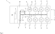
- the figures show possible features of a transportable plant 1 according to the invention for the combustion of undesirable gases.
- the gases may, for example, be hydrocarbons which, during the cleaning or maintenance of fuel tanks (eg at refineries or filling stations), are extracted from the corresponding tank and then have to be disposed of.
- the system 1 has in principle a support platform 5, for example in the form of a truck support structure or a corresponding platform of a truck trailer or truck semi-trailer 18.
- a support platform 5 for example in the form of a truck support structure or a corresponding platform of a truck trailer or truck semi-trailer 18.
- inlets. 2 available, which can be connected by means of appropriate hose or pipes with the object to be degassed.
- the plant 1 have a pipe and / or tube bearing 16, in which said tube or hose pieces 17 are stored until their use and can be spent together with the system 1 from one location to the next.
- a partition 19 (for example in the form of a wall) may be present with the aid of which the tube and / or tube bearing 16 and / or the control and / or regulating unit 4 are spatially separated from the burner units 6.
- the carrier platform 5 may have a housing (eg in the form of side walls or an upper ceiling section), so that the individual components of the installation 1 are shielded towards the outside. If a ceiling section is present, then it should (and possibly also sections of the side walls) be designed such that it can be at least partially opened during operation of the burner units 6 in order not to hinder the exit of the exhaust gases (or the entry of air).
- a housing eg in the form of side walls or an upper ceiling section
- the inlet or inlets 2 open into one or more main gas lines 11, which in turn, for example, via corresponding branches 13 (of which for reasons of clarity only one is provided with a reference numeral and which are shown in comparison with the main gas line 11 with thinner lines) is in communication with a burner assembly 3, wherein the burner assembly 3 according to the invention consists of a plurality of separate burner units 6.
- the individual burner units 6, which may be arranged, for example, in two rows extending in the longitudinal direction of the carrier platform 5, each have a separate combustion chamber 7, in which the gas to be burned can be burnt.
- the burner units 6 each have at least one exhaust gas chimney 8, via which the exhaust gases produced during combustion can escape from the plant 1.
- control and / or regulating unit 4 is present, which, as explained in more detail below, the control and / or regulation of the system. 1 serves and with the help of which the number of involved in the combustion of undesired gases burner units 6 is adjustable.
- this can also have at least one fan 9 (fan or blower), which can be placed for example between an inlet 2 and a portion of a main gas line 11.
- fan 9 fan or blower
- a flame arrester 10 should be present, which must be passed by the gas (regardless of whether the system's own fan 9 is bypassed or used) and which prevents a flame front from one of the burner units 6 to outside the plant 1 can reproduce.
- valves 14 can be assigned to the aforementioned branches 13 (or alternatively to the corresponding inlet regions of the individual burner units 6) or to the described bypass 12 by small circles, only one of which is provided with a reference numeral).
- the valves 14 may be manually and / or automatically actuated, wherein they are in the latter case preferably in communication with the control and / or regulating unit 4, so that it can regulate the degree of opening of the valves 14.
- sensors 15 may be present, with the aid of which physical quantities, such as pressures or temperatures, can be measured.
- sensors 15 are conceivable with the help of which the type, composition and / or the volume flow of the gas to be combusted or the exhaust gases let determine.
- there are finally measured values which can serve as the basis for the connection and disconnection of individual burner units 6, for the regulation of said valves 14 or else the supply of combustible supporting gas to selected burner units 6.
- the system 1 can be optimally adapted to the conditions on site, wherein the adjustment can be made manually or (possibly) automatically with the aid of the control and / or regulating unit 4.
- the sensors 15 may be placed in the area of the intake 2 or inlets 2, the main gas line (s) 11, the branches 13 and / or the individual burner units 6 or their combustion chambers 7 or exhaust chimneys 8.
Landscapes
- Engineering & Computer Science (AREA)
- Mechanical Engineering (AREA)
- General Engineering & Computer Science (AREA)
- Environmental & Geological Engineering (AREA)
- Incineration Of Waste (AREA)
Claims (13)
- Installation transportable pour brûler des gaz indésirables, par exemple sous forme d'hydrocarbures ou d'ammoniac,- avec au moins une admission (2), qui peut être reliée à une conduite de tube ou de tuyau, et par laquelle le gaz à brûler peut être acheminé à l'installation (1),- avec un arrangement de brûleurs (3) pour brûler les gaz indésirables,- avec une unité de commande et/ou de régulation (4) pour la commande et/ou la régulation de l'installation (1), et- avec une plateforme support (5) commune, sur laquelle sont fixés les composants de l'installation (1) cités, de sorte que l'installation (1) soit transportable sous forme d'unité unique,caractérisée en ce que
l'arrangement (3) de brûleurs comprend plusieurs unités (6) de brûleurs séparées, qui disposent respectivement d'une propre chambre de combustion (7) et d'une propre cheminée d'évacuation (8) des gaz, et qui peuvent être chargées d'un gaz à brûler indépendamment l'une de l'autre et/ou exploitées indépendamment l'une de l'autre. - Installation selon la revendication précédente, caractérisée en ce que les unités (6) de brûleurs sont de même type.
- Installation selon la revendication précédente, caractérisée en ce qu'une partie au moins des unités (6) de brûleurs possèdent un débit calorifique d'au moins 0,3 mégawatts, de préférence d'au moins 1,0 mégawatts, de manière davantage préférée d'au moins 2,0 mégawatts, de manière particulièrement préférée d'au moins 3,0 mégawatts.
- Installation selon l'une des revendications précédentes, caractérisée en ce que les unités (6) de brûleurs sont disposées en plusieurs, de préférence deux rangées s'étendant dans le sens longitudinal de l'installation (1).
- Installation selon l'une des revendications précédentes, caractérisée en ce que l'installation (1) comporte au moins un ventilateur (9) relié avec la plateforme support (5), à l'aide duquel le gaz à brûler peut être acheminé dans l'installation (1).
- Installation selon l'une des revendications précédentes, caractérisée en ce que le ventilateur (9) ou l'admission ou les admissions (2) sont reliés à une ou plusieurs conduites (11) de gaz principales via un coupe-flamme (10) intermédiaire, lesquelles conduites (11) de gaz principales sont respectivement en relation avec plusieurs unités (6) de brûleurs ou avec toutes les unités (6) de brûleurs et via lesquelles le gaz à brûler peut être acheminé aux unités (6) de brûleurs.
- Installation selon la revendication précédente, caractérisée en ce que la/les conduite(s) (11) de gaz principale(s) comporte(nt) un by-pass (12), de sorte que le gaz à brûler puisse être acheminé aux unités (6) de brûleurs en contournement du ventilateur (9).
- Installation selon l'une des revendications 6 et 7, caractérisée en ce que la/les conduites (11) de gaz principale(s) est/sont en relation (respectivement) via des dérivations (13) avec une multitude ou toutes les unités (6) de brûleurs, sachant que des vannes (14) sont attribuées aux dérivations (13), par lesquelles les dérivations (13) peuvent être fermées en cas de besoin.
- Installation selon l'une des revendications précédentes, caractérisée en ce que l'installation (1) comportent des capteurs (15), avec lesquelles il est possible de surveiller un ou plusieurs paramètres physiques durant la combustion et que l'unité de commande et/ou de régulation (4) se présente sous une forme pour réguler le nombre d'unités (6) de brûleurs en service en fonction des valeurs de mesure des capteurs (15).
- Installation selon l'une des revendications précédentes, caractérisée en ce que l'installation (1) compote un support (16) de conduite et/ou de tuyau également relié avec la plateforme support (5) pour accueillir une multitude de tronçons (17) de conduite et/ou de tuyau.
- Installation selon l'une des revendications précédentes, caractérisée en ce que la plateforme support (5) est relation avec un moyen de transport, par exemple un camion, une remorque de camion ou une semi-remorque (18) de camion, et peut être exploitée avec ce moyen de transport sans devoir être au préalable détachée ou démontée du moyen de transport.
- Procédé pour brûler des gaz indésirables, par exemple sous forme d'hydrocarbures ou d'ammoniac, à l'aide d'une installation (1) selon l'une ou plusieurs des revendications précédentes,- dans lequel l'installation (1) est acheminée au lieu de l'objet contenant le gaz devant être brûlé, par exemple un réservoir de gaz ou de liquide, un pipeline ou un navire porte-barges,- dans lequel au moins une admission (2) de l'installation (1) est reliée avec l'objet à dégazer à l'aide d'une conduite de tube et/ou de tuyau- dans lequel le gaz présent dans l'objet et devant être brûlé est acheminé dans l'installation (1), et- dans lequel le gaz est brûlé à l'aide d'un arrangement de brûleurs (3) propre à l'installation,caractérisé en ce que le gaz devant être brulé, avant la combustion, est divisé en plusieurs flux de gaz à l'aide de l'installation (1), et que les différents flux de gaz sont répartis sur plusieurs unités (6) de brûleurs de l'arrangement de brûleurs (3) et que les différents flux de gaz sont brûlés séparément, sachant que les débits volumiques des flux de gaz acheminés aux différentes unités (6) de brûleurs sont régulés individuellement ou peuvent être régulés individuellement
- Procédé selon la revendication précédente, caractérisé en ce que la répartition en les différents flux de gaz et/ou la répartition des flux de gaz sur les différentes unités (6) de brûleurs s'effectue(nt) compte tenu de grandeurs physiques, en particulier compte tenu de pressions et/ou de températures, qui sont déterminées de préférence dans la zone des différentes unités (6) de brûleurs.
Priority Applications (1)
| Application Number | Priority Date | Filing Date | Title |
|---|---|---|---|
| PL14179624T PL2835582T3 (pl) | 2013-08-05 | 2014-08-04 | Przenośne urządzenie i sposób spalania niepożądanych gazów |
Applications Claiming Priority (1)
| Application Number | Priority Date | Filing Date | Title |
|---|---|---|---|
| DE102013108412.5A DE102013108412A1 (de) | 2013-08-05 | 2013-08-05 | Transportable Anlage und Verfahren zur Verbrennung von unerwünschten Gasen |
Publications (3)
| Publication Number | Publication Date |
|---|---|
| EP2835582A2 EP2835582A2 (fr) | 2015-02-11 |
| EP2835582A3 EP2835582A3 (fr) | 2015-02-18 |
| EP2835582B1 true EP2835582B1 (fr) | 2017-01-04 |
Family
ID=51263272
Family Applications (1)
| Application Number | Title | Priority Date | Filing Date |
|---|---|---|---|
| EP14179624.3A Active EP2835582B1 (fr) | 2013-08-05 | 2014-08-04 | Installation transportable et procédé destiné à la combustion de gaz indésirables |
Country Status (5)
| Country | Link |
|---|---|
| EP (1) | EP2835582B1 (fr) |
| DE (1) | DE102013108412A1 (fr) |
| ES (1) | ES2618060T3 (fr) |
| PL (1) | PL2835582T3 (fr) |
| PT (1) | PT2835582T (fr) |
Families Citing this family (3)
| Publication number | Priority date | Publication date | Assignee | Title |
|---|---|---|---|---|
| CN109099503B (zh) * | 2018-09-06 | 2023-07-28 | 黑龙江赫尔特生物质能源发展有限公司 | 可变出力、多燃料、低排放、高效率的模块式热力系统 |
| DE102021109809A1 (de) * | 2021-04-19 | 2022-10-20 | Dürr Systems Ag | Thermische rohgasbehandlungsvorrichtung |
| DE102021109810A1 (de) | 2021-04-19 | 2022-10-20 | Dürr Systems Ag | Werkstückbearbeitungsanlage und verfahren zum herstellen und betreiben einer solchen werkstückbearbeitungsanlage |
Family Cites Families (4)
| Publication number | Priority date | Publication date | Assignee | Title |
|---|---|---|---|---|
| BE787528A (fr) * | 1971-08-12 | 1973-02-12 | British Petroleum Co | Perfectionnements relatifs aux cheminees de |
| US4255120A (en) * | 1978-12-05 | 1981-03-10 | Straitz John F Iii | Portable safety flare for combustion of waste gases |
| US6267931B1 (en) * | 1994-02-03 | 2001-07-31 | Earth Resources Corporation | Reconfigurable waste treatment system |
| DE102011003972A1 (de) * | 2011-02-11 | 2012-08-16 | Endegs Gmbh | System und Verfahren zum Entgasen einer Lager- und/oder Transporteinrichtung für Feststoffe, Flüssigkeiten und/oder Gase |
-
2013
- 2013-08-05 DE DE102013108412.5A patent/DE102013108412A1/de not_active Withdrawn
-
2014
- 2014-08-04 EP EP14179624.3A patent/EP2835582B1/fr active Active
- 2014-08-04 ES ES14179624.3T patent/ES2618060T3/es active Active
- 2014-08-04 PL PL14179624T patent/PL2835582T3/pl unknown
- 2014-08-04 PT PT141796243T patent/PT2835582T/pt unknown
Non-Patent Citations (1)
| Title |
|---|
| None * |
Also Published As
| Publication number | Publication date |
|---|---|
| PL2835582T3 (pl) | 2017-07-31 |
| PT2835582T (pt) | 2017-03-10 |
| EP2835582A3 (fr) | 2015-02-18 |
| ES2618060T3 (es) | 2017-06-20 |
| DE102013108412A1 (de) | 2015-02-05 |
| EP2835582A2 (fr) | 2015-02-11 |
Similar Documents
| Publication | Publication Date | Title |
|---|---|---|
| DE2836531A1 (de) | Fliessbett-verbrennungsvorrichtung | |
| DE2519609A1 (de) | Vorrichtung zum entfernen des russes aus abgasen von brennkraftmaschinen, insbesondere dieselbrennkraftmaschinen | |
| EP2835582B1 (fr) | Installation transportable et procédé destiné à la combustion de gaz indésirables | |
| AT506459A2 (de) | Vorrichtung und verfahren zur reinigung von schadstoffhaltigem abgas | |
| DE102017118951B4 (de) | Kühlung einer Abdampfung von Flüssiggas zum Antrieb von Maschinen, Anlagen oder Fahrzeugen | |
| EP3428533B1 (fr) | Dispositif de gaz d'échappement pour une installation de combustion dans un véhicule | |
| DE2445057A1 (de) | Muellverbrennungsofen | |
| EP4177528A1 (fr) | Appareil de chauffage à rendement amélioré | |
| EP1984673B1 (fr) | Dispositif pour la combustion de matières organiques | |
| CH643346A5 (de) | Verfahren und heizungsanlage zur nutzung der heissen abgase eines waermeerzeugers. | |
| EP3210890B1 (fr) | Refroidissement de carburant pour un moteur | |
| EP3655701A1 (fr) | Brûleur | |
| EP1558421B1 (fr) | Dispositif pour eliminer des etincelles d'un courant de gaz | |
| DE69215823T2 (de) | Verfahren und Anlage zur Entsorgung von Abfällen | |
| DE3837989A1 (de) | Kompaktes verbrennungsgeraet | |
| DE102017217106A1 (de) | Heißgaserzeuger zum Erwärmen von Gas sowie Anlage für die Asphaltherstellung mit einem derartigen Heißgaserzeuger | |
| EP2811229B1 (fr) | Installation transportable destinée à la combustion de gaz indésirables | |
| DE69325502T2 (de) | Heizanlage für Räume | |
| DE202011005561U1 (de) | Vorwärmeinrichtung | |
| DE202014002500U1 (de) | Heizsystem | |
| DE4439798A1 (de) | Feuerlöscheinrichtung | |
| EP3056811B1 (fr) | Procédé de refroidissement de résidus solides d'un processus de combustion | |
| DE202013103423U1 (de) | Aufnahmevorrichtung für brennbares Material | |
| EP1771683B1 (fr) | Dispositif de postcombustion thermique et procede d'exploitation correspondant | |
| DE3612892C2 (fr) |
Legal Events
| Date | Code | Title | Description |
|---|---|---|---|
| PUAL | Search report despatched |
Free format text: ORIGINAL CODE: 0009013 |
|
| PUAI | Public reference made under article 153(3) epc to a published international application that has entered the european phase |
Free format text: ORIGINAL CODE: 0009012 |
|
| 17P | Request for examination filed |
Effective date: 20140804 |
|
| AK | Designated contracting states |
Kind code of ref document: A2 Designated state(s): AL AT BE BG CH CY CZ DE DK EE ES FI FR GB GR HR HU IE IS IT LI LT LU LV MC MK MT NL NO PL PT RO RS SE SI SK SM TR |
|
| AX | Request for extension of the european patent |
Extension state: BA ME |
|
| AK | Designated contracting states |
Kind code of ref document: A3 Designated state(s): AL AT BE BG CH CY CZ DE DK EE ES FI FR GB GR HR HU IE IS IT LI LT LU LV MC MK MT NL NO PL PT RO RS SE SI SK SM TR |
|
| AX | Request for extension of the european patent |
Extension state: BA ME |
|
| RIC1 | Information provided on ipc code assigned before grant |
Ipc: F23G 5/40 20060101AFI20150114BHEP Ipc: F23G 7/06 20060101ALI20150114BHEP |
|
| R17P | Request for examination filed (corrected) |
Effective date: 20150725 |
|
| RBV | Designated contracting states (corrected) |
Designated state(s): AL AT BE BG CH CY CZ DE DK EE ES FI FR GB GR HR HU IE IS IT LI LT LU LV MC MK MT NL NO PL PT RO RS SE SI SK SM TR |
|
| 17Q | First examination report despatched |
Effective date: 20160113 |
|
| REG | Reference to a national code |
Ref country code: DE Ref legal event code: R079 Ref document number: 502014002388 Country of ref document: DE Free format text: PREVIOUS MAIN CLASS: F23G0005400000 Ipc: F23J0001020000 |
|
| GRAP | Despatch of communication of intention to grant a patent |
Free format text: ORIGINAL CODE: EPIDOSNIGR1 |
|
| RIC1 | Information provided on ipc code assigned before grant |
Ipc: F23J 1/02 20060101AFI20160711BHEP |
|
| INTG | Intention to grant announced |
Effective date: 20160810 |
|
| GRAS | Grant fee paid |
Free format text: ORIGINAL CODE: EPIDOSNIGR3 |
|
| GRAA | (expected) grant |
Free format text: ORIGINAL CODE: 0009210 |
|
| AK | Designated contracting states |
Kind code of ref document: B1 Designated state(s): AL AT BE BG CH CY CZ DE DK EE ES FI FR GB GR HR HU IE IS IT LI LT LU LV MC MK MT NL NO PL PT RO RS SE SI SK SM TR |
|
| REG | Reference to a national code |
Ref country code: GB Ref legal event code: FG4D Free format text: NOT ENGLISH |
|
| REG | Reference to a national code |
Ref country code: CH Ref legal event code: EP |
|
| REG | Reference to a national code |
Ref country code: AT Ref legal event code: REF Ref document number: 859621 Country of ref document: AT Kind code of ref document: T Effective date: 20170115 |
|
| REG | Reference to a national code |
Ref country code: IE Ref legal event code: FG4D Free format text: LANGUAGE OF EP DOCUMENT: GERMAN |
|
| REG | Reference to a national code |
Ref country code: DE Ref legal event code: R096 Ref document number: 502014002388 Country of ref document: DE |
|
| REG | Reference to a national code |
Ref country code: RO Ref legal event code: EPE |
|
| REG | Reference to a national code |
Ref country code: PT Ref legal event code: SC4A Ref document number: 2835582 Country of ref document: PT Date of ref document: 20170310 Kind code of ref document: T Free format text: AVAILABILITY OF NATIONAL TRANSLATION Effective date: 20170302 |
|
| REG | Reference to a national code |
Ref country code: NL Ref legal event code: FP |
|
| REG | Reference to a national code |
Ref country code: NO Ref legal event code: T2 Effective date: 20170104 |
|
| REG | Reference to a national code |
Ref country code: LT Ref legal event code: MG4D |
|
| REG | Reference to a national code |
Ref country code: ES Ref legal event code: FG2A Ref document number: 2618060 Country of ref document: ES Kind code of ref document: T3 Effective date: 20170620 |
|
| PG25 | Lapsed in a contracting state [announced via postgrant information from national office to epo] |
Ref country code: GR Free format text: LAPSE BECAUSE OF FAILURE TO SUBMIT A TRANSLATION OF THE DESCRIPTION OR TO PAY THE FEE WITHIN THE PRESCRIBED TIME-LIMIT Effective date: 20170405 Ref country code: LT Free format text: LAPSE BECAUSE OF FAILURE TO SUBMIT A TRANSLATION OF THE DESCRIPTION OR TO PAY THE FEE WITHIN THE PRESCRIBED TIME-LIMIT Effective date: 20170104 Ref country code: IS Free format text: LAPSE BECAUSE OF FAILURE TO SUBMIT A TRANSLATION OF THE DESCRIPTION OR TO PAY THE FEE WITHIN THE PRESCRIBED TIME-LIMIT Effective date: 20170504 Ref country code: FI Free format text: LAPSE BECAUSE OF FAILURE TO SUBMIT A TRANSLATION OF THE DESCRIPTION OR TO PAY THE FEE WITHIN THE PRESCRIBED TIME-LIMIT Effective date: 20170104 Ref country code: HR Free format text: LAPSE BECAUSE OF FAILURE TO SUBMIT A TRANSLATION OF THE DESCRIPTION OR TO PAY THE FEE WITHIN THE PRESCRIBED TIME-LIMIT Effective date: 20170104 |
|
| REG | Reference to a national code |
Ref country code: FR Ref legal event code: PLFP Year of fee payment: 4 |
|
| PG25 | Lapsed in a contracting state [announced via postgrant information from national office to epo] |
Ref country code: LV Free format text: LAPSE BECAUSE OF FAILURE TO SUBMIT A TRANSLATION OF THE DESCRIPTION OR TO PAY THE FEE WITHIN THE PRESCRIBED TIME-LIMIT Effective date: 20170104 Ref country code: BG Free format text: LAPSE BECAUSE OF FAILURE TO SUBMIT A TRANSLATION OF THE DESCRIPTION OR TO PAY THE FEE WITHIN THE PRESCRIBED TIME-LIMIT Effective date: 20170404 Ref country code: RS Free format text: LAPSE BECAUSE OF FAILURE TO SUBMIT A TRANSLATION OF THE DESCRIPTION OR TO PAY THE FEE WITHIN THE PRESCRIBED TIME-LIMIT Effective date: 20170104 Ref country code: SE Free format text: LAPSE BECAUSE OF FAILURE TO SUBMIT A TRANSLATION OF THE DESCRIPTION OR TO PAY THE FEE WITHIN THE PRESCRIBED TIME-LIMIT Effective date: 20170104 |
|
| PGFP | Annual fee paid to national office [announced via postgrant information from national office to epo] |
Ref country code: FR Payment date: 20180411 Year of fee payment: 18 |
|
| REG | Reference to a national code |
Ref country code: DE Ref legal event code: R097 Ref document number: 502014002388 Country of ref document: DE |
|
| PG25 | Lapsed in a contracting state [announced via postgrant information from national office to epo] |
Ref country code: EE Free format text: LAPSE BECAUSE OF FAILURE TO SUBMIT A TRANSLATION OF THE DESCRIPTION OR TO PAY THE FEE WITHIN THE PRESCRIBED TIME-LIMIT Effective date: 20170104 Ref country code: SK Free format text: LAPSE BECAUSE OF FAILURE TO SUBMIT A TRANSLATION OF THE DESCRIPTION OR TO PAY THE FEE WITHIN THE PRESCRIBED TIME-LIMIT Effective date: 20170104 |
|
| PGFP | Annual fee paid to national office [announced via postgrant information from national office to epo] |
Ref country code: CZ Payment date: 20170726 Year of fee payment: 4 Ref country code: NO Payment date: 20170828 Year of fee payment: 4 |
|
| PLBE | No opposition filed within time limit |
Free format text: ORIGINAL CODE: 0009261 |
|
| STAA | Information on the status of an ep patent application or granted ep patent |
Free format text: STATUS: NO OPPOSITION FILED WITHIN TIME LIMIT |
|
| PG25 | Lapsed in a contracting state [announced via postgrant information from national office to epo] |
Ref country code: SM Free format text: LAPSE BECAUSE OF FAILURE TO SUBMIT A TRANSLATION OF THE DESCRIPTION OR TO PAY THE FEE WITHIN THE PRESCRIBED TIME-LIMIT Effective date: 20170104 Ref country code: DK Free format text: LAPSE BECAUSE OF FAILURE TO SUBMIT A TRANSLATION OF THE DESCRIPTION OR TO PAY THE FEE WITHIN THE PRESCRIBED TIME-LIMIT Effective date: 20170104 |
|
| PGFP | Annual fee paid to national office [announced via postgrant information from national office to epo] |
Ref country code: PT Payment date: 20170726 Year of fee payment: 4 |
|
| PG25 | Lapsed in a contracting state [announced via postgrant information from national office to epo] |
Ref country code: SI Free format text: LAPSE BECAUSE OF FAILURE TO SUBMIT A TRANSLATION OF THE DESCRIPTION OR TO PAY THE FEE WITHIN THE PRESCRIBED TIME-LIMIT Effective date: 20170104 |
|
| REG | Reference to a national code |
Ref country code: CH Ref legal event code: PL |
|
| PG25 | Lapsed in a contracting state [announced via postgrant information from national office to epo] |
Ref country code: MC Free format text: LAPSE BECAUSE OF FAILURE TO SUBMIT A TRANSLATION OF THE DESCRIPTION OR TO PAY THE FEE WITHIN THE PRESCRIBED TIME-LIMIT Effective date: 20170104 |
|
| PG25 | Lapsed in a contracting state [announced via postgrant information from national office to epo] |
Ref country code: CH Free format text: LAPSE BECAUSE OF NON-PAYMENT OF DUE FEES Effective date: 20170831 Ref country code: LI Free format text: LAPSE BECAUSE OF NON-PAYMENT OF DUE FEES Effective date: 20170831 |
|
| REG | Reference to a national code |
Ref country code: IE Ref legal event code: MM4A |
|
| PG25 | Lapsed in a contracting state [announced via postgrant information from national office to epo] |
Ref country code: IE Free format text: LAPSE BECAUSE OF NON-PAYMENT OF DUE FEES Effective date: 20170804 |
|
| REG | Reference to a national code |
Ref country code: FR Ref legal event code: PLFP Year of fee payment: 5 |
|
| PG25 | Lapsed in a contracting state [announced via postgrant information from national office to epo] |
Ref country code: MT Free format text: LAPSE BECAUSE OF FAILURE TO SUBMIT A TRANSLATION OF THE DESCRIPTION OR TO PAY THE FEE WITHIN THE PRESCRIBED TIME-LIMIT Effective date: 20170104 |
|
| REG | Reference to a national code |
Ref country code: NO Ref legal event code: MMEP |
|
| GBPC | Gb: european patent ceased through non-payment of renewal fee |
Effective date: 20180804 |
|
| PG25 | Lapsed in a contracting state [announced via postgrant information from national office to epo] |
Ref country code: NO Free format text: LAPSE BECAUSE OF NON-PAYMENT OF DUE FEES Effective date: 20180831 Ref country code: CZ Free format text: LAPSE BECAUSE OF NON-PAYMENT OF DUE FEES Effective date: 20180804 Ref country code: LU Free format text: LAPSE BECAUSE OF NON-PAYMENT OF DUE FEES Effective date: 20180804 |
|
| PG25 | Lapsed in a contracting state [announced via postgrant information from national office to epo] |
Ref country code: PT Free format text: LAPSE BECAUSE OF NON-PAYMENT OF DUE FEES Effective date: 20190204 |
|
| PG25 | Lapsed in a contracting state [announced via postgrant information from national office to epo] |
Ref country code: HU Free format text: LAPSE BECAUSE OF FAILURE TO SUBMIT A TRANSLATION OF THE DESCRIPTION OR TO PAY THE FEE WITHIN THE PRESCRIBED TIME-LIMIT; INVALID AB INITIO Effective date: 20140804 |
|
| PG25 | Lapsed in a contracting state [announced via postgrant information from national office to epo] |
Ref country code: CY Free format text: LAPSE BECAUSE OF FAILURE TO SUBMIT A TRANSLATION OF THE DESCRIPTION OR TO PAY THE FEE WITHIN THE PRESCRIBED TIME-LIMIT Effective date: 20170104 Ref country code: GB Free format text: LAPSE BECAUSE OF NON-PAYMENT OF DUE FEES Effective date: 20180804 |
|
| PG25 | Lapsed in a contracting state [announced via postgrant information from national office to epo] |
Ref country code: MK Free format text: LAPSE BECAUSE OF FAILURE TO SUBMIT A TRANSLATION OF THE DESCRIPTION OR TO PAY THE FEE WITHIN THE PRESCRIBED TIME-LIMIT Effective date: 20170104 |
|
| PG25 | Lapsed in a contracting state [announced via postgrant information from national office to epo] |
Ref country code: TR Free format text: LAPSE BECAUSE OF FAILURE TO SUBMIT A TRANSLATION OF THE DESCRIPTION OR TO PAY THE FEE WITHIN THE PRESCRIBED TIME-LIMIT Effective date: 20170104 |
|
| PG25 | Lapsed in a contracting state [announced via postgrant information from national office to epo] |
Ref country code: AL Free format text: LAPSE BECAUSE OF FAILURE TO SUBMIT A TRANSLATION OF THE DESCRIPTION OR TO PAY THE FEE WITHIN THE PRESCRIBED TIME-LIMIT Effective date: 20170104 |
|
| REG | Reference to a national code |
Ref country code: NL Ref legal event code: PD Owner name: SIS GMBH; DE Free format text: DETAILS ASSIGNMENT: CHANGE OF OWNER(S), MERGE; FORMER OWNER NAME: ENDEGS GMBH Effective date: 20250203 Ref country code: NL Ref legal event code: HC Owner name: ETS DEGASSING GMBH; DE Free format text: DETAILS ASSIGNMENT: CHANGE OF OWNER(S), CHANGE OF OWNER(S) NAME; FORMER OWNER NAME: SIS GMBH Effective date: 20250203 |
|
| REG | Reference to a national code |
Ref country code: DE Ref legal event code: R081 Ref document number: 502014002388 Country of ref document: DE Owner name: ETS DEGASSING GMBH, DE Free format text: FORMER OWNER: ENDEGS GMBH, 85055 INGOLSTADT, DE |
|
| REG | Reference to a national code |
Ref country code: AT Ref legal event code: PC Ref document number: 859621 Country of ref document: AT Kind code of ref document: T Owner name: ETS DEGASSING GMBH, DE Effective date: 20250310 |
|
| REG | Reference to a national code |
Ref country code: BE Ref legal event code: PD Owner name: ETS DEGASSING GMBH; DE Free format text: DETAILS ASSIGNMENT: CHANGE OF OWNER(S), MERGE; FORMER OWNER NAME: VERLEYEN CHRIST'L-MARIE Effective date: 20250218 |
|
| PGFP | Annual fee paid to national office [announced via postgrant information from national office to epo] |
Ref country code: NL Payment date: 20250826 Year of fee payment: 12 |
|
| PGFP | Annual fee paid to national office [announced via postgrant information from national office to epo] |
Ref country code: ES Payment date: 20250902 Year of fee payment: 12 |
|
| PGFP | Annual fee paid to national office [announced via postgrant information from national office to epo] |
Ref country code: DE Payment date: 20250613 Year of fee payment: 12 |
|
| PGFP | Annual fee paid to national office [announced via postgrant information from national office to epo] |
Ref country code: PL Payment date: 20250731 Year of fee payment: 12 Ref country code: IT Payment date: 20250827 Year of fee payment: 12 |
|
| PGFP | Annual fee paid to national office [announced via postgrant information from national office to epo] |
Ref country code: BE Payment date: 20250822 Year of fee payment: 12 |
|
| PGFP | Annual fee paid to national office [announced via postgrant information from national office to epo] |
Ref country code: AT Payment date: 20250822 Year of fee payment: 12 |
|
| PGFP | Annual fee paid to national office [announced via postgrant information from national office to epo] |
Ref country code: RO Payment date: 20250721 Year of fee payment: 12 |