EP2835618A1 - Durchflussmesser mit einem Rotor für ein wasserführendes Haushaltsgerät - Google Patents
Durchflussmesser mit einem Rotor für ein wasserführendes Haushaltsgerät Download PDFInfo
- Publication number
- EP2835618A1 EP2835618A1 EP14178852.1A EP14178852A EP2835618A1 EP 2835618 A1 EP2835618 A1 EP 2835618A1 EP 14178852 A EP14178852 A EP 14178852A EP 2835618 A1 EP2835618 A1 EP 2835618A1
- Authority
- EP
- European Patent Office
- Prior art keywords
- rotor
- flow meter
- active surface
- water
- wings
- Prior art date
- Legal status (The legal status is an assumption and is not a legal conclusion. Google has not performed a legal analysis and makes no representation as to the accuracy of the status listed.)
- Granted
Links
Images


Classifications
-
- G—PHYSICS
- G01—MEASURING; TESTING
- G01F—MEASURING VOLUME, VOLUME FLOW, MASS FLOW OR LIQUID LEVEL; METERING BY VOLUME
- G01F1/00—Measuring the volume flow or mass flow of fluid or fluent solid material wherein the fluid passes through a meter in a continuous flow
- G01F1/05—Measuring the volume flow or mass flow of fluid or fluent solid material wherein the fluid passes through a meter in a continuous flow by using mechanical effects
- G01F1/06—Measuring the volume flow or mass flow of fluid or fluent solid material wherein the fluid passes through a meter in a continuous flow by using mechanical effects using rotating vanes with tangential admission
- G01F1/075—Measuring the volume flow or mass flow of fluid or fluent solid material wherein the fluid passes through a meter in a continuous flow by using mechanical effects using rotating vanes with tangential admission with magnetic or electromagnetic coupling to the indicating device
-
- G—PHYSICS
- G01—MEASURING; TESTING
- G01F—MEASURING VOLUME, VOLUME FLOW, MASS FLOW OR LIQUID LEVEL; METERING BY VOLUME
- G01F15/00—Details of, or accessories for, apparatus of groups G01F1/00 - G01F13/00 insofar as such details or appliances are not adapted to particular types of such apparatus
- G01F15/006—Details of, or accessories for, apparatus of groups G01F1/00 - G01F13/00 insofar as such details or appliances are not adapted to particular types of such apparatus characterised by the use of a particular material, e.g. anti-corrosive material
Definitions
- the invention relates to a flow meter for measuring a flow of a fluid in a fluid line according to the preamble of patent claim 1, wherein the flow meter has a rotor which can be arranged at least in sections within the fluid line and a sensor device which can be arranged outside the fluid line for detecting a rotation of an active surface of the rotor.
- the invention relates to a rotor for a flow meter and a water-conducting household appliance with a flow meter.
- Modern water-conducting domestic appliances such as instantaneous water heaters are regularly equipped with a flowmeter for flow measurement or volume flow measurement.
- Known flowmeters operate on the Hall principle. They have a rotor which can be arranged at least in sections in a supply line and a Hall sensor which can be arranged outside the supply line for detecting a rotation of the rotor due to the water flowing in through the supply line.
- the rotor may be an impeller whose wings represent effective surfaces and for this purpose consist of a permanent magnet.
- the impeller made of a plastic material and the rotor have at least one permanent magnet as the active surface.
- the object of the invention is to provide a flow meter for measuring a flow of a fluid in a fluid line, which eliminates the aforementioned disadvantages and whose rotor has a high dynamics. Furthermore, it is an object of the invention to provide a rotor for such a flow meter and a water-conducting household appliance.
- a flow meter according to the invention for measuring a flow of a fluid in a fluid line has a rotor which can be arranged at least in sections within the fluid line and a sensor device which can be arranged outside the fluid line for detecting a rotation of an active surface of the rotor.
- the sensor device has a resonant circuit, the rotor is permanently magnet-free and the at least one active surface is electrically conductive.
- eddy currents are induced in the at least one electrically conductive surface by the resonant circuit, which lead depending on the position of the rotor to a different degrees of damping of the resonant circuit.
- more power is supplied to the resonant circuit and detects the rotation of the rotor, which is then again a measure of the flow or the volume flow.
- the rotor consists of a non-permanent magnetic material, but preferably of food-safe materials, no harmful particles can get into the fluid.
- the rotor Since the rotor is not permanently magnetic, it also has no magnetic attraction, so that also the risk of adhesion by iron-containing dirt particles is prevented on the rotor. Furthermore, the design of the rotor without a permanent magnet significantly reduces its weight, which has a positive effect on the dynamics of the flow meter. It achieves faster response and less lag time than traditional flow meters.
- the electrical active surface contains, for example, copper or a copper alloy.
- the resonant circuit can be designed with or without a capacitor.
- the rotor is made of an electrically insulating material and the at least one active surface is an electrically conductive coating of the rotor. This may be limited to a rotor area or extend completely over the rotor.
- the rotor is preferably an injection-molded part made of plastic and is characterized in addition to a low weight by a technically simple and cost-effective production.
- the coating is preferably galvanic, by vapor deposition, by printing or by a comparative method on the rotor applied. This allows the coating to be applied very thinly.
- the rotor is made of an electrically conductive material.
- the rotor can be coated completely electrically conductive. This embodiment eliminates the application of one or the electrically conductive coating.
- the rotor itself can be made, for example, from a light metal such as cast aluminum.
- the resonant circuit can be designed to save energy if the at least one active surface is arranged radially on the outside relative to the axis of rotation. As a result, the at least one surface is guided past the resonant circuit at a small distance, so that the formation of eddy currents which have a small extension in space is sufficient.
- a distance between the resonant circuit and the at least one passing electrically conductive active surface is almost a wall thickness of the fluid line in the connection region of the resonant circuit. The distance is made up of the wall thickness and a tip-side vane gap between the rotor and the fluid line together to prevent friction of the rotor to the fluid line.
- the rotor has at least two diametrically arranged pairs of wings, each having two wings are connected to each other via at least one annular arc, which forms a region in each case an active surface.
- the active surfaces each extend at least with a longer range in the direction of rotation.
- the rotor can continue to be made lightweight.
- each pair of wings are connected together at the ends via two annular arcs and each pair of wings has an effective surface which extends in each case over the two annular arcs and outer edges of the wings.
- the wings can each have two facing away from each other parallel wing surfaces.
- the wing surfaces are preferably flat.
- curved wing surfaces, curved wing surfaces, helical wing surfaces and the like are also possible.
- An inventive rotor for a flow meter according to the invention consists of an iron-free material and has at least one electrically conductive surface. Such a rotor is characterized by a high level of dynamics and by a very low maintenance or freedom from maintenance, since iron-containing dirt particles can not attach to the rotor.
- An inventive water-conducting household appliance has a flow meter according to the invention.
- the water-conducting household appliance for example, a water heater or a hot water tank, which allows the provision of drinking water in a high purity by the use of the flow meter according to the invention.
- a water heater allows due to the high dynamics of the flow meter, a precise adjustment of a target temperature. Due to the lack of a Hall sensor, the water-bearing household appliance is inexpensive.
- the invention is particularly suitable for providing a water-conducting household appliance, in particular a water heater or a beverage dispenser such as a coffee machine or a coffee machine and the like, which allows the provision of drinking water and / or a drink in a high purity, low maintenance and low cost.
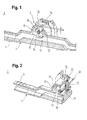
- a longitudinal section through a line section 1 of a water-conducting household appliance 2 is shown.
- the water-bearing device is, for example, a water heater and the line section 1 an inlet line of the water heater.
- the household appliance 2 may also be a beverage dispenser such as a coffee machine.
- the line section 1 has a connection piece 4 for connection to a wall installation and a flow meter 6 arranged downstream of the connection piece 4.
- the flow meter 6 is arranged in or on a cylindrical housing section 8 of the line section 1.
- the housing section 8 extends transversely to the line section 1 and has an interior which is in fluid communication with the line section 1 via a radial opening 10.
- the flow meter 6 has a rotor 12 which is arranged in the interior of the housing section 2, and a sensor device 14 arranged outside the housing section 8.
- the rotor 12 covers the opening 10 completely or in sections and is rotatably mounted on a fixed axis of rotation 18 of the rotor 12 transversely to the flow direction of the water in the line section 1.
- the axis of rotation 18 is received in a bearing portion 20 of the flow meter 6, which seals the interior to the outside environment via a sealing ring 22.
- the sensor device 14 comprises a resonant circuit with a corresponding control, regulating and evaluation electronics.
- the control, regulation and evaluation is generally referred to as electronics. It serves to detect a rotation of the rotor 12, which in the embodiment shown here has two opposing active surfaces 16, 17, which will be explained in more detail below.
- the resonant circuit has in the embodiment shown here at least one coil, a capacitor and a power supply. Of course, the resonant circuit may comprise further electrical elements or be designed, for example, without a capacitor.
- the resonant circuit is preferably operated in MHz and is in the embodiment shown here on a flat surface 24 of the housing section 8 is arranged.
- the bearing portion 20 has two mutually opposite relative to the rotation axis 18 stops 26, 28 which are formed like ears and each having a frontal abutment surface 30, 32 for limiting an axial mounting position of the rotor 12 in the housing section 8.
- two locking lugs 34, 36 are arranged laterally, which engage in a corresponding latching recess of the housing portion 8 side.
- a plate-like handle member 38 which extends between the stops 26, 28.
- For radial positioning of the rotor 12 in the interior of the bearing portion 20 has a cylindrical portion 41, in the peripheral surface of a circumferential groove 40 is introduced for receiving the sealing ring 22.
- the axis of rotation 18 of the rotor 12 is according to FIG. 3 end provided with a respective annular locking groove 42, 44.
- the as shown in FIG. 3 Right detent groove 42 dives into a corresponding counter-element of the bearing section 20, whereby the axis of rotation 18 is positively connected to the bearing section 20.
- the as shown in FIG. 3 left detent groove 44 cooperates with a retractable on the axis of rotation 18 securing ring 46, by means of which the rotor 12 is secured on the axis of rotation 18 in the axial direction.
- a spacer 48, 50 for optimizing a rotational behavior of the rotor 12 can each be arranged laterally of the rotor 12.
- the locking ring 46 and the spacers 48, 50 are free of iron and preferably consist of a plastic material or a light metal such as aluminum or titanium.
- the latter can have a central decrement 52 in its front side facing the bearing section 20, so that it radially surrounds a central axial projection 53 of the locating section 20 extending from the cylinder section 41.
- the rotor 12 has a hub 54 for mounting on the axis of rotation 18 and two diametrically opposed pairs of wings, each having two wings 56, 58 and 60, 62.
- the rotor 12 is thus formed as an impeller. He is in the embodiment shown here, a one-piece injection molded part made of a plastic and thus consists of an electrically insulating material.
- the rotor 12 can also be made of an electrically conductive material and, for example, be an aluminum casting.
- the rotor 12 is permanent magnet-free.
- the wings 56, 58 and 60, 62 each have two parallel planar wing surfaces 64a and 66a, 66b and 68a, 68b and 70a, 70b. Due to the chosen perspective in the FIGS. 6 and 7 is a wing surface 66b of the wing 56 can not be seen and thus not numbered. However, it is viewed in the circumferential direction of the wing surface 66a opposite.
- the wings 56, 58 and 60, 62 are each connected via two end-side annular arcs 72, 74 and 76, 78 in pairs.
- annular arches 72, 74 and 76, 78 are thus arranged on the tip side of the rotor 12, wherein the annular arcs 72, 74 and 76, 78 of a pair of wings in the direction of the axis of rotation 18 and spaced apart in the axial direction.
- radially outer arc surface 80, 82, 84, 86 of the annular arches 72, 74 and 76, 78 and radially outer outer edges 88, 90 and 92, 94 of the wings 56, 58 and 60, 62 together form the respective hatched here indicated active surfaces 16, 17 of the wing pairs.
- the rotor 12 shown here has two opposing radially outer and in particular ring-like active surfaces 16, 17, wherein the surfaces 80, 88, 82, 90, the active surface 16 and the surfaces 84, 92, 86, 94 form the active surface 17.
- the active surfaces 16, 17 are electrically conductive and food-safe coatings, such as copper coatings.
- the coatings can, for example, be applied by electroplating, by vapor deposition, printing and the like.
- the active surfaces 16, 17 are relative to the axis of rotation 18 radially outer peripheral surfaces of the rotor 12 and in one rotation alternately in a minimum radial distance a of the sensor device 14 positioned ( FIG. 1 ).
- the radial distance a corresponds approximately to approximately a wall thickness of the housing section 8 in the region of the surface 24 plus a tip gap in order to prevent grinding of the wings 56, 58 and 60, 62 along the housing section 8.
- the entire rotor 12 acts as an effective surface.
- the active surfaces 16, 17 are used exclusively for interacting with the sensor device 1, whereas the wing surfaces are used exclusively for driving the rotor 12.
- the active surfaces 16, 17 and the wing surfaces 64a and 66a, 66b and 68a, 68b and 70a, 70b fulfill different functions and can be optimally adjusted to these.
- the rotor 12 in Rotation is offset and the resonant circuit sensor device 14 is energized, eddy currents are respectively induced in the active surfaces 16, 17, which lead to an attenuation of the resonant circuit of the sensor device.
- the damping results in a power loss, which is detected and evaluated by the electronics of the sensor device 14. Depending on the required additional power to compensate for the damping or depending on the degree of damping determines the electronics the respective volume flow.
- the rotor 12 is not only bearing section side provided with a central de-rating 52, but also on the circlip side.
- the backup ring-side demotion 96 allows immersion of the locking ring 46 between the pair of wings or the wings 56, 58 and 60, 62, whereby they can be extended either in the direction of its axis of rotation 18 or the axis of rotation 18 can be reduced.
- the other elements such as sensor device 14 with resonant circuit, annular arcs 72, 74 and 76, 78 and active surfaces 16, 17 are equal to the previous embodiment of the FIGS. 1 to 7 ,
- the ring arc 74 is due to the perspective in FIG. 8 not recognizable.
- a flowmeter for measuring a flow of a fluid in a fluid line, with a at least partially arrangeable within the fluid line rotor and with an outside of the fluid line can be arranged sensor means for detecting a rotation of an active surface of the rotor, wherein the sensor device comprises a resonant circuit, the rotor none Permanent magnet has and at least one active surface is electrically conductive, a rotor for such a flow meter, and a water-conducting household appliance.
Landscapes
- Physics & Mathematics (AREA)
- Fluid Mechanics (AREA)
- General Physics & Mathematics (AREA)
- Electromagnetism (AREA)
- Measuring Volume Flow (AREA)
Abstract
Description
- Die Erfindung betrifft einen Durchflussmesser zum Messen eines Durchflusses eines Fluides in einer Fluidleitung nach dem Oberbegriff des Patentanspruchs 1, wobei der Durchflussmesser einen innerhalb der Fluidleitung zumindest abschnittsweise anordbaren Rotor und eine außerhalb der Fluidleitung anordbare Sensoreinrichtung zur Erfassung einer Rotation einer Wirkfläche des Rotors hat. Zudem betrifft die Erfindung einen Rotor für einen Durchflussmesser sowie ein wasserführendes Haushaltsgerät mit einem Durchflussmesser.
- Moderne wasserführende Haushaltsgeräte wie Durchlauferhitzer sind regelmäßig mit einem Durchflussmesser zur Durchflussmessung bzw. Volumenstrommessung ausgestattet. Bekannte Durchflussmesser arbeiten nach dem Hall-Prinzip. Sie haben einen in einer Zulaufleitung zumindest abschnittsweise anordbaren Rotor und einen außerhalb der Zulaufleitung anordbaren Hall-Sensor zur Erfassung einer Rotation des Rotors aufgrund des durch die Zulaufleitung einströmenden Wassers. Der Rotor kann hierzu ein Flügelrad sein, dessen Flügel Wirkflächen darstellen und hierzu aus einem Dauermagneten bestehen. Wie in der
DE 10 2006 027 477 A1 gezeigt, kann alternativ das Flügelrad aus einem Kunststoffmaterial bestehen und der Rotor zumindest einen Dauermagneten als Wirkfläche aufweisen. Problematisch bei derartigen Durchflussmessern ist, dass sich Bestandteile von den Dauermagneten lösen können und somit in das Trinkwasser gelangen. Zudem kann es zu Anhaftung von eisenhaltigen Schmutzpartikeln an dem Rotor kommen. Zudem zeichnen sich derartige Rotoren durch die Magneten durch ein hohes Gewicht aus, was sich nachteilig auf die Dynamik der Durchflussmesser auswirkt. - Aufgabe der Erfindung ist es, einen Durchflussmesser zum Messen eines Durchflusses eines Fluids in einer Fluidleitung zu schaffen, der die vorgenannten Nachteile beseitigt und dessen Rotor eine hohe Dynamik aufweist. Des Weiteren ist es Aufgabe der Erfindung, einen Rotor für einen derartigen Durchflussmesser und ein wasserführendes Haushaltsgerät zu schaffen.
- Diese Aufgabe wir gelöst durch einen Durchflussmesser mit den Merkmalen des Patentanspruch 1, durch einen Rotor mit den Merkmalen des Patentanspruchs 8 und durch ein wasserführendes Haushaltsgerät mit den Merkmalen des Patentanspruchs 9. Vorteilhafte Aus- und Weiterbildungen, welche einzeln oder in Kombination miteinander eingesetzt werden können, sind Gegenstand der abhängigen Ansprüche.
- Ein erfindungsgemäßer Durchflussmesser zum Messen eines Durchflusses eines Fluids in einer Fluidleitung, hat einen innerhalb der Fluidleitung zumindest abschnittsweise anordbaren Rotor und eine außerhalb der Fluidleitung anordbare Sensoreinrichtung zur Erfassung einer Rotation einer Wirkfläche des Rotors. Erfindungsgemäß weist die Sensoreinrichtung einen Schwingkreis auf, der Rotor ist dauermagnetfrei und die zumindest eine Wirkfläche ist elektrisch leitend.
- Bei einer Drehung des Rotors aufgrund des durch die Fluidleitung strömenden Fluids, beispielsweise Trinkwasser, werden durch den Schwingkreis Wirbelströme in der zumindest einen elektrisch leitenden Fläche induziert, die je nach Position des Rotors zu einer unterschiedlich starken Dämpfung des Schwingkreises führen. Zum Ausgleich des Dämpfungsverlustes wird dem Schwingkreis mehr Leistung zugeführt und die Drehung des Rotors erkannt, die dann wieder ein Maß für den Durchfluss bzw. den Volumenstrom ist. Dadurch, dass der Rotor aus einem nicht dauermagnetischen Material besteht, sondern bevorzugterweise aus lebensmittelechten Materialien, können keine gesundheitsbedenkliche Partikel in das Fluid gelangen. Da der Rotor nicht dauermagnetisch ist, weist er auch keine magnetische Anziehung auf, sodass ebenfalls die Gefahr einer Anhaftung durch eisenhaltige Schmutzpartikeln an dem Rotor unterbunden ist. Ferner wird durch die Ausführung des Rotors ohne Dauermagnet sein Gewicht erheblich reduziert, was sich positiv auf die Dynamik des Durchflussmessers auswirkt. Es wird ein schnelleres Ansprechverhalten und eine geringere Nachlaufzeit als bei herkömmlichen Durchflussmessern erreicht. Die elektrische Wirkfläche enthält beispielsweise Kupfer bzw. eine Kupferlegierung. Der Schwingkreis kann mit oder ohne Kondensator ausgeführt sein.
- Bei einem Ausführungsbeispiel besteht der Rotor aus einem elektrisch isolierenden Material und die zumindest eine Wirkfläche ist eine elektrisch leitende Beschichtung des Rotors. Diese kann auf einen Rotorbereich begrenzt sein oder sich vollständig über den Rotor erstrecken. Der Rotor ist bevorzugterweise ein Spritzgussteil aus Kunststoff und zeichnet sich so neben einem geringen Gewicht durch eine technisch einfache und kostengünstige Herstellung aus. Die Beschichtung wird bevorzugterweise galvanisch, per Bedampfung, per Bedruckung oder durch ein vergleichendes Verfahren auf den Rotor aufgebracht. Hierdurch lässt sich die Beschichtung sehr dünn auftragen.
- Bei einem alternativen Ausführungsbeispiel besteht der Rotor aus einem elektrisch leitenden Material. Zusätzlich kann der Rotor vollständig elektrisch leitend beschichtet sein. diesem Ausführungsbeispiel entfällt die Aufbringung einer bzw. der elektrisch leitenden Beschichtung. Der Rotor an sich kann beispielsweise aus einem Leichtmetall wie Aluminiumguss hergestellt werden.
- Der Schwingkreis lässt sich energiesparend ausführen, wenn die zumindest eine Wirkfläche bezogen auf die Drehachse radial außen angeordnet ist. Hierdurch wird die zumindest eine Fläche in einem geringen Abstand an dem Schwingkreis vorbeigeführt, sodass die Ausbildung von Wirbelströmen genügt, die eine geringe Erstreckung im Raum aufweisen. Idealerweise beträgt ein Abstand zwischen dem Schwingkreis und der zumindest einen vorbeiführenden elektrisch leitenden Wirkfläche nahezu eine Wandstärke der Fluidleitung im Anbindungsbereich des Schwingkreises. Der Abstand setzt sich dabei aus der Wandstärke und einem spitzenseitigen Flügelspalt zwischen dem Rotor und der Fluidleitung zusammen, um eine Reibung des Rotors an der Fluidleitung zu verhindern.
- Bevorzugterweise hat der Rotor zumindest zwei diametral angeordnete Flügelpaare, deren jeweils zwei Flügel über zumindest einen Ringbogen miteinander verbunden sind, der einen Bereich jeweils einer Wirkfläche bildet. Durch den jeweils zumindest einen Ringbogen erstrecken sich die Wirkflächen jeweils zumindest mit einem längeren Bereich in Drehrichtung. Gleichzeitig kann der Rotor weiterhin leichtgewichtig ausgeführt werden.
- Bei einem bevorzugten Ausführungsbeispiel sind die Flügel jedes Flügelpaares endseitig über jeweils zwei Ringbögen miteinander verbunden und jedes Flügelpaar hat eine Wirkfläche, die sich jeweils über die zwei Ringbögen und Außenkanten der Flügel erstreckt. Durch die jeweils zwei Ringbögen in Kombination mit den jeweiligen Außenkanten wird pro Flügel quasi eine ringartige Wirkfläche geschaffen, die die Entstehung von Wirbelströmen begünstigt.
- Zur Reduzierung eines fertigungstechnischen Aufwandes können die Flügel jeweils zwei voneinander abgewandte parallele Flügelflächen haben. Aus fertigungstechnischer Sicht sind die Flügelflächen bevorzugterweise eben. Selbstverständlich sind jedoch auch gewölbte Flügelflächen, gebogene Flügelflächen, schraubenartige Flügelflächen und dergleichen möglich.
- Ein erfindungsgemäßer Rotor für einen erfindungsgemäßen Durchflussmesser besteht aus einem eisenfreien Material und hat zumindest eine elektrisch leitende Fläche. Ein derartiger Rotor zeichnet sich durch eine hohe Dynamik und durch eine sehr geringe Wartung bzw. durch Wartungsfreiheit aus, da sich eisenhaltige Schmutzpartikel nicht an dem Rotor festsetzen können.
- Ein erfindungsgemäßes wasserführendes Haushaltgerät hat einen erfindungsgemäßen Durchflussmesser. Das wasserführende Haushaltsgerät ist beispielsweise ein Durchlauferhitzer oder ein Warmwasserspeicher, der sich durch die Verwendung des erfindungsgemäßen Durchflussmessers die Bereitstellung von Trinkwasser in einer hohen Reinheit ermöglicht. Zudem erlaubt ein derartiger Durchlauferhitzer aufgrund der hohen Dynamik des Durchflussmessers eine präzise Einstellung einer Soll-Temperatur. Aufgrund des Verzichtes auf einen Hall-Sensor ist das wasserführende Haushaltgerät kostengünstig.
- Die Erfindung eignet sich insbesondere zur Bereitstellung eines wasserführenden Haushaltsgerätes, insbesondere ein Durchlauferhitzer oder ein Getränkespender wie eine Kaffeemaschine bzw. ein Kaffeevollautomat und dergleichen, das die Bereitstellung von Trinkwasser und/oder eines Getränks in einer hohen Reinheit erlaubt, wartungsarm und kostengünstig ist.
- Im Folgenden werden bevorzugte Ausführungsbeispiele der Erfindung anhand schematischer Darstellungen näher erläutert. Es zeigen:
- Figur 1
- einen Längsschnitt durch einen Leitungsabschnitt eines erfindungsgemäßen wasserführenden Haushaltsgerätes mit einem ersten Ausführungsbeispiel eines erfindungsgemäßen Durchflussmessers,
- Figur 2
- einen Schnitt durch den Durchflussmesser entlang seiner Rotordrehachse aus
Figur 1 , - Figur 3
- eine Explosionsdarstellung des Durchflussmessers,
- Figuren 4 und 5
- perspektivische Darstellungen des Durchflussmessers,
- Figuren 6 und 7
- perspektivische Darstellungen eines Rotors des Durchflussmessers, und
- Figur 8
- ein alternatives Ausführungsbeispiel des erfindungsgemäßen Durchflussmessers.
- In den
Figuren 1 und 2 ist ein Längsschnitt durch einen Leitungsabschnitt 1 eines wasserführenden Haushaltsgerätes 2 gezeigt. Das wasserführende Gerät ist beispielsweise ein Durchlauferhitzer und der Leitungsabschnitt 1 eine Zulaufleitung des Durchlauferhitzers. Das Haushaltsgerät 2 kann jedoch auch ein Getränkespender wie ein Kaffeevollautomat sein. - Der Leitungsabschnitt 1 hat ein Anschlussstück 4 zum Verbinden mit einer Wandinstallation und ein stromabwärts zum Anschlussstück 4 angeordneten Durchflussmesser 6. Der Durchflussmesser 6 ist in bzw. an einem zylinderförmigen Gehäuseabschnitt 8 des Leitungsabschnittes 1 angeordnet. Der Gehäuseabschnitt 8 erstreckt sich quer zum Leitungsabschnitt 1 und hat einen Innenraum, der über eine radiale Öffnung 10 mit dem Leitungsabschnitt 1 in Fluidverbindung steht.
- Der Durchflussmesser 6 hat einen Rotor 12, der in dem Innenraum des Gehäuseabschnittes 2 angeordnet ist, und einen außerhalb des Gehäuseabschnittes 8 angeordnete Sensoreinrichtung 14.
- Der Rotor 12 überdeckt die Öffnung 10 vollständig oder abschnittsweise und ist auf einer feststehenden Drehachse 18 des Rotors 12 quer zur Strömungsrichtung des Wassers in den Leitungsabschnitt 1 drehbar gelagert. Die Drehachse 18 ist in einen Lagerabschnitt 20 des Durchflussmessers 6 aufgenommen, der über einen Dichtring 22 den Innenraum zur Außenumgebung abdichtet.
- Die Sensoreinrichtung 14 umfasst einen Schwingkreis mit einer entsprechenden Steuer-, Regel- und Auswerteelektronik. Die Steuer-, Regel- und Auswerteelektronik wird im Folgen allgemein als Elektronik bezeichnet. Er dient zur Erfassung einer Rotation des Rotors 12, der hierzu in dem hier gezeigten Ausführungsbeispiel zwei zueinander entgegengesetzte Wirkflächen 16, 17 hat, die im Folgenden noch näher erläutert werden. Der Schwingkreis weist in dem hier gezeigten Ausführungsbeispiel zumindest eine Spule, einen Kondensator und eine Stromversorgung auf. Selbstverständlich kann der Schwingkreis weitere elektrische Elemente aufweisen oder beispielsweise ohne einen Kondensator ausgeführt sein. Der Schwingkreis wird bevorzugterweise in MHz betrieben und ist in dem hier gezeigten Ausführungsbeispiel an einer planen Oberfläche 24 des Gehäuseabschnittes 8 angeordnet.
- Gemäß den
Figuren 3, 4 und 5 hat der Lagerabschnitt 20 zwei bezogen auf die Drehachse 18 zueinander entgegengesetzte Anschläge 26, 28, die ohrenartig ausgebildet sind und jeweils eine stirnseitige Anschlagfläche 30, 32 zum Begrenzen einer axialen Einbauposition des Rotors 12 in dem Gehäuseabschnitt 8 aufweisen. Zur Lagesicherung des Lageabschnittes 20 an dem Gehäuseabschnitt 8 sind seitlich der Anschläge 26, 28 zwei Rastnasen 34, 36 angeordnet, die in eine entsprechende Rastvertiefung des Gehäuseabschnittes 8 eingreifen. Zur Handhabung des weist der Lageabschnitt 20 ein plattenartiger Griffelement 38 auf, der sich zwischen den Anschlägen 26, 28 erstreckt. Zur radialen Positionierung des Rotors 12 in dem Innenraum hat der Lagerabschnitt 20 einen Zylinderabschnitt 41, in deren Umfangsfläche eine Umfangsnut 40 zur Aufnahme des Dichtrings 22 eingebracht ist. - Die Drehachse 18 des Rotors 12 ist gemäß
Figur 3 endseitig mit jeweils einer ringartigen Rastnut 42, 44 versehen. Die gemäß der Darstellung inFigur 3 rechte Rastnut 42 taucht in ein korrespondierendes Gegenelement des Lageabschnittes 20, ein wodurch die Drehachse 18 formschlüssig mit dem Lageabschnitt 20 verbunden ist. Die gemäß der Darstellung inFigur 3 linke Rastnut 44 wirkt mit einem auf die Drehachse 18 aufschiebbaren Sicherungsring 46 zusammen, mittels dem der Rotor 12 auf der Drehachse 18 in Axialrichtung gesichert ist. Seitlich des Rotors 12 kann jeweils eine Distanzscheibe 48, 50 zum Optimieren eines Drehverhaltens des Rotors 12 angeordnet sein. Der Sicherungsring 46 und die Distanzscheiben 48, 50 sind eisenfrei und bestehen bevorzugterweise aus einem Kunststoffmaterial oder einem Leichtmetall wie Aluminium oder Titan. - Zur Reduzierung einer axialen Baulänge des Rotors 12 kann dieser in seinem dem Lagerabschnitt 20 zugewandten Stirnseite eine zentrale Rückstufung 52 aufweisen, sodass es einen, sich von dem Zylinderabschnitt 41 erstreckenden zentralen Axialvorsprung 53 des Lageabschnitt 20 radial umgreift.
- Gemäß den
Figuren 6 und 7 hat der Rotor 12 eine Nabe 54 zur Lagerung auf der Drehachse 18 und zwei diametral zueinander angeordnete Flügelpaare, die jeweils zwei Flügel 56, 58 und 60, 62 aufweisen. Der Rotor 12 ist somit als ein Flügelrad ausgebildet. Er ist in dem hier gezeigten Ausführungsbeispiel ein einteiliges Spritzgussteil aus einem Kunststoff und besteht somit aus einem elektrisch isolierenden Material. Selbstverständlich kann der Rotor 12 auch aus einem elektrisch leitfähigen Material bestehen und beispielsweise ein Aluminiumgussteil sein. Erfindungsgemäß ist der Rotor 12 dauermagnetfrei. - Die Flügel 56, 58 und 60, 62 haben jeweils zwei parallele ebene Flügelflächen 64a und 66a, 66b und 68a, 68b und 70a, 70b. Aufgrund der gewählten Perspektive in den
Figuren 6 und 7 ist eine Flügelfläche 66b des Flügels 56 nicht zu erkennen und somit nicht beziffert. Sie liegt jedoch in Umfangsrichtung betrachtet der Flügelfläche 66a gegenüber. Die Flügel 56, 58 und 60, 62 sind jeweils über zwei endseitige Ringbögen 72, 74 und 76, 78 paarweise miteinander verbunden. Die Ringbögen 72, 74 und 76, 78 sind somit spitzenseitig des Rotors 12 angeordnet, wobei die Ringbögen 72, 74 und 76, 78 eines Flügelpaares in Richtung der Drehachse 18 bzw. in Axialrichtung voneinander beabstandet sind. - Eine jeweils auf die Drehachse 18 bezogen radial äußere Bogenfläche 80, 82, 84, 86 der Ringbögen 72, 74 und 76, 78 sowie radial äußere Außenkanten 88, 90 und 92, 94 der Flügel 56, 58 und 60, 62 bilden zusammen jeweils die hier schraffiert angedeuteten Wirkflächen 16, 17 der Flügelpaare. Somit hat der hier gezeigte Rotor 12 zwei voneinander abgewandte radial äußere und insbesondere ringartige Wirkflächen 16, 17, wobei die Flächen 80, 88, 82, 90 die Wirkfläche 16 und die Flächen 84, 92, 86, 94 die Wirkfläche 17 bilden. Die Wirkflächen 16, 17 sind elektrisch leitende und lebensmittelechte Beschichtungen, beispielsweise Kupferbeschichtungen. Die Beschichtungen können beispielsweise galvanisch, aufgedampft, bedruckt und dergleichen aufgetragen werden. Die Wirkflächen 16, 17 sind bezogen auf die Drehachse 18 radiale Außenumfangsflächen des Rotors 12 und bei einer Umdrehung abwechselnd in einem minimalen Radialabstand a von der Sensoreinrichtung 14 positioniert (
Figur 1 ). Der Radialabstand a entspricht etwa der in etwa einer Wandstärke des Gehäuseabschnittes 8 im Bereich der Oberfläche 24 zuzüglich eines Spitzenspaltes, um ein Schleifen der Flügel 56, 58 und 60, 62 entlang des Gehäuseabschnitts 8 zu verhindern. Wenn der Rotor 12 aus einem Leichtmetallmaterial besteht, wirkt der gesamte Rotor 12 als Wirkfläche. - Die Wirkflächen 16, 17 dienen ausschließlich zum Zusammenwirken mit der Sensoreinrichtung 1, wohingegen die Flügelflächen ausschließlich zum Antreiben des Rotors 12 dienen. Somit erfüllen die Wirkflächen 16, 17 und die Flügelflächen 64a und 66a, 66b und 68a, 68b und 70a, 70b unterschiedliche Funkionen und können auf diese jeweils optimal eingestellt werden.
- Wenn nun aufgrund einer Wasserströmung in dem Leitungsabschnitt 1 der Rotor 12 in Rotation versetzt wird und der Schwingkreis Sensoreinrichtung 14 bestromt ist, werden in den Wirkflächen 16, 17 jeweils Wirbelströme induziert, die zu einer Dämpfung des Schwingkreises der Sensoreinrichtung führen. Die Dämpfung resultiert in einem Leistungsabfall, der von der Elektronik der Sensoreinrichtung 14 erfasst und ausgewertet wird. Je nach der benötigen Zusatzleistung zum Ausgleich der Dämpfung bzw. je nach dem Dämpfungsgrad ermittelt so die Elektronik den jeweiligen Volumenstrom.
- Bei dem in
Figur 8 gezeigten zweiten Ausführungsbeispiel des erfindungsgemäßen Durchflussmessers 6 ist der Rotor 12 nicht nur lagerabschnittseitig mit einer zentralen Rückstufung 52 versehen, sondern ebenfalls sicherungsringseitig. Die sicherungsringseitige Rückstufung 96 ermöglicht ein Eintauchen des Sicherungsringes 46 zwischen die Flügelpaare bzw. die Flügel 56, 58 und 60, 62, wodurch diese entweder in Richtung ihrer Drehachse 18 verlängert werden können oder die Drehachse 18 reduziert werden kann. Die sonstigen Elemente wie Sensoreinrichtung 14 mit Schwingkreis, Ringbögen 72, 74 und 76, 78 und Wirkflächen 16, 17 sind gleich dem vorhergehenden Ausführungsbeispiel nach denFiguren 1 bis 7 . Der Ringbogen 74 ist aufgrund der Perspektive inFigur 8 nicht zu erkennen. - Offenbart ist ein Durchflussmesser zum Messen eines Durchflusses eines Fluids in einer Fluidleitung, mit einem innerhalb der Fluidleitung zumindest abschnittsweise anordbaren Rotor und mit einer außerhalb der Fluidleitung anordbaren Sensoreinrichtung zur Erfassung einer Rotation einer Wirkfläche des Rotors, wobei die Sensoreinrichtung ein Schwingkreis aufweist, der Rotor keinen Dauermagneten besitzt und die zumindest eine Wirkfläche elektrisch leitend ist, ein Rotor für einen derartigen Durchflussmesser, sowie ein wasserführendes Haushaltsgerät.
-
- 1
- Leitungsabschnitt eines
- 2
- wasserführendes Haushaltsgerät
- 4
- Anschlussstück
- 6
- Durchflussmesser
- 8
- Gehäuseabschnitt
- 10
- Öffnung
- 12
- Rotor
- 14
- Sensoreinrichtung
- 16
- Wirkfläche
- 17
- Wirkfläche
- 18
- Drehachse
- 20
- Lagerabschnitt
- 22
- Dichtring
- 24
- Oberfläche
- 26
- Anschlag
- 28
- Anschlag
- 30
- Anschlagfläche
- 32
- Anschlagfläche
- 34
- Rastnase
- 36
- Rastnase
- 38
- Griffelement
- 40
- Umfangsnut
- 41
- Zylinderabschnitt
- 42
- Rastnut
- 44
- Rastnut
- 46
- Sicherungsring
- 48
- Distanzscheibe
- 50
- Distanzscheibe
- 52
- Rückstufung
- 53
- Axialvorsprung
- 54
- Nabe
- 56
- Flügel
- 58
- Flügel
- 60
- Flügel
- 62
- Flügel
- 64a, b
- Flügelfläche
- 66a, b
- Flügelfläche
- 68a, b
- Flügelfläche
- 70a, b
- Flügelfläche
- 72
- Ringbogen
- 74
- Ringbogen
- 76
- Ringbogen
- 78
- Ringbogen
- 80
- Bogenfläche
- 82
- Bogenfläche
- 84
- Bogenfläche
- 86
- Bogenfläche
- 88
- Außenkanten
- 90
- Außenkanten
- 92
- Außenkanten
- 94
- Außenkanten
- 96
- Rückstufung
- a
- Radialabstand
Claims (9)
- Durchflussmesser (6) zum Messen eines Durchflusses eines Fluids in einer Fluidleitung (1), mit einem innerhalb der Fluidleitung (1) zumindest abschnittsweise anordbaren Rotor (12) und mit einer außerhalb der Fluidleitung (1) anordbaren Sensoreinrichtung (14) zur Erfassung einer Rotation einer Wirkfläche (16, 17) des Rotors (12), dadurch gekennzeichnet, dass die Sensoreinrichtung (14) einen Schwingkreis aufweist, der Rotor (12) dauermagnetfrei ist und die zumindest eine Wirkfläche (16, 17) elektrisch leitend ist.
- Durchflussmesser nach Anspruch 1, wobei der Rotor (12) aus einem elektrisch isolierenden Material besteht und die zumindest eine Wirkfläche (16, 17) eine elektrisch leitende Beschichtung des Rotors (12) ist.
- Durchflussmesser nach Anspruch 1, wobei der Rotor (12) aus einem elektrisch leitenden Material besteht.
- Durchflussmesser nach Anspruch 1, 2 oder 3, wobei die zumindest eine Wirkfläche (16, 17) bezogen auf die Drehachse (18) radial außen angeordnet ist.
- Durchflussmesser nach einem der vorhergehenden Ansprüche, wobei der Rotor (12) zumindest zwei diametral angeordnete Flügelpaare aufweist, deren jeweils zwei Flügel (56, 58, 60, 62) über zumindest einen Ringbogen (72, 74, 76, 78) miteinander verbunden sind, der einen Bereich jeweils einer Wirkfläche (16, 17) bildet.
- Durchflussmesser nach Anspruch 5, wobei die Flügel (56, 58, 60, 62) jedes Flügelpaares endseitig über jeweils zwei Ringbögen (72, 74, 76, 78) miteinander verbunden sind und jedes Flügelpaar eine Wirkfläche (16, 17) aufweist, die sich jeweils über die zwei Ringbögen (72, 74, 76, 78) und Außenkanten der Flügel (56, 58, 60, 62) erstreckt.
- Durchflussmesser nach Anspruch 5 oder 6, wobei die Flügel (56, 58, 60, 62) jeweils zwei voneinander abgewandte parallele Flügelflächen (64a, 66a, 66b, 68a, 68b, 70a, 70b)haben.
- Rotor (12) für einen Durchflussmesser (6) nach einem der vorhergehenden Ansprüche.
- Wasserführendes Haushaltsgerät (2) mit einem Durchflussmesser nach einem der Ansprüche 1 bis 8.
Applications Claiming Priority (1)
| Application Number | Priority Date | Filing Date | Title |
|---|---|---|---|
| DE102013215604.9A DE102013215604A1 (de) | 2013-08-07 | 2013-08-07 | Durchflussmesser, Rotor und wasserführendes Haushaltsgerät |
Publications (2)
| Publication Number | Publication Date |
|---|---|
| EP2835618A1 true EP2835618A1 (de) | 2015-02-11 |
| EP2835618B1 EP2835618B1 (de) | 2020-02-26 |
Family
ID=51225394
Family Applications (1)
| Application Number | Title | Priority Date | Filing Date |
|---|---|---|---|
| EP14178852.1A Active EP2835618B1 (de) | 2013-08-07 | 2014-07-29 | Durchflussmesser mit einem Rotor für ein wasserführendes Haushaltsgerät |
Country Status (3)
| Country | Link |
|---|---|
| EP (1) | EP2835618B1 (de) |
| DE (1) | DE102013215604A1 (de) |
| PT (1) | PT2835618T (de) |
Cited By (1)
| Publication number | Priority date | Publication date | Assignee | Title |
|---|---|---|---|---|
| EP3037789A1 (de) * | 2014-12-18 | 2016-06-29 | BSH Hausgeräte GmbH | Durchflussmesser, rotor und wasserführendes haushaltsgerät |
Families Citing this family (1)
| Publication number | Priority date | Publication date | Assignee | Title |
|---|---|---|---|---|
| DE102014226416A1 (de) * | 2014-12-18 | 2016-06-23 | BSH Hausgeräte GmbH | Durchflussmesser, Rotor und wasserführendes Haushaltsgerät |
Citations (6)
| Publication number | Priority date | Publication date | Assignee | Title |
|---|---|---|---|---|
| DE1801421A1 (de) * | 1967-10-09 | 1969-08-14 | United Aircraft Corp | Tachometer |
| DE2616323A1 (de) * | 1976-04-14 | 1977-10-27 | Kueppers Karl | Durchflussmessgeraet, insbesondere fuer kleine und kleinste durchflussmengen |
| DE4026692A1 (de) * | 1990-08-23 | 1992-02-27 | Honsberg & Co Kg | Durchflussmessvorrichtung |
| US5450760A (en) * | 1993-10-18 | 1995-09-19 | Lew; Hyok S. | Turbine flowmeter with capacitive transducer |
| DE102006027477A1 (de) | 2005-06-14 | 2006-12-28 | Eltek S.P.A., Casale Monferrato | Durchflussmesser mit Hallsensor, System und Vorrichtung die diesen einsetzen, und Verfahren zu seiner Montage |
| DE102008043613A1 (de) * | 2008-11-10 | 2010-05-20 | BSH Bosch und Siemens Hausgeräte GmbH | Elektro-Haushaltsgerät mit zumindest einer Flüssigkeitszuführung |
Family Cites Families (5)
| Publication number | Priority date | Publication date | Assignee | Title |
|---|---|---|---|---|
| FR2459456A1 (fr) * | 1979-06-20 | 1981-01-09 | Thomson Csf | Debitmetre a turbine |
| ATE85425T1 (de) * | 1988-10-27 | 1993-02-15 | Gas & Wassermesserfab Ag | Induktiver umdrehungssensor fuer fluegelraddurchflussmesser. |
| DE19725977C2 (de) * | 1997-06-19 | 2001-11-29 | Kulmbacher Klimageraete | Elektrischer Durchlauferhitzer und Verfahren zum Überwachen des Wasserzulaufs |
| AT409302B (de) * | 1999-03-23 | 2002-07-25 | Vaillant Gmbh | Flügelrad-durchflussmesser |
| DE102008038955B4 (de) * | 2008-08-13 | 2011-05-19 | Hydrometer Gmbh | Kreisförmige Modulatorscheibe für einen Flügelradzähler |
-
2013
- 2013-08-07 DE DE102013215604.9A patent/DE102013215604A1/de not_active Ceased
-
2014
- 2014-07-29 PT PT141788521T patent/PT2835618T/pt unknown
- 2014-07-29 EP EP14178852.1A patent/EP2835618B1/de active Active
Patent Citations (6)
| Publication number | Priority date | Publication date | Assignee | Title |
|---|---|---|---|---|
| DE1801421A1 (de) * | 1967-10-09 | 1969-08-14 | United Aircraft Corp | Tachometer |
| DE2616323A1 (de) * | 1976-04-14 | 1977-10-27 | Kueppers Karl | Durchflussmessgeraet, insbesondere fuer kleine und kleinste durchflussmengen |
| DE4026692A1 (de) * | 1990-08-23 | 1992-02-27 | Honsberg & Co Kg | Durchflussmessvorrichtung |
| US5450760A (en) * | 1993-10-18 | 1995-09-19 | Lew; Hyok S. | Turbine flowmeter with capacitive transducer |
| DE102006027477A1 (de) | 2005-06-14 | 2006-12-28 | Eltek S.P.A., Casale Monferrato | Durchflussmesser mit Hallsensor, System und Vorrichtung die diesen einsetzen, und Verfahren zu seiner Montage |
| DE102008043613A1 (de) * | 2008-11-10 | 2010-05-20 | BSH Bosch und Siemens Hausgeräte GmbH | Elektro-Haushaltsgerät mit zumindest einer Flüssigkeitszuführung |
Cited By (1)
| Publication number | Priority date | Publication date | Assignee | Title |
|---|---|---|---|---|
| EP3037789A1 (de) * | 2014-12-18 | 2016-06-29 | BSH Hausgeräte GmbH | Durchflussmesser, rotor und wasserführendes haushaltsgerät |
Also Published As
| Publication number | Publication date |
|---|---|
| PT2835618T (pt) | 2020-04-07 |
| EP2835618B1 (de) | 2020-02-26 |
| DE102013215604A1 (de) | 2015-02-12 |
Similar Documents
| Publication | Publication Date | Title |
|---|---|---|
| EP2626567B1 (de) | Pumpengehäuse | |
| DE202008018234U1 (de) | Pumpe mit Heizeinrichtung | |
| DE102008035740A1 (de) | Magnetisch induktiver Durchflussmesser mit einer kombinierte magnetische Flussleitmittel umfassenden Elektromagenteinheit | |
| DE102012105966A1 (de) | Drehwinkelsensor | |
| EP2835618B1 (de) | Durchflussmesser mit einem Rotor für ein wasserführendes Haushaltsgerät | |
| DE10306873B4 (de) | Wasserzähler mit nach aussen gedichtetem Messeinsatz | |
| AT502408B1 (de) | Wassermengenmesser | |
| DE102017129991A1 (de) | Fluidverteilervorrichtung, insbesondere Wasserverteilervorrichtung | |
| EP2244078B1 (de) | Wasser /Wärmezähler mit einem Gebergehäuse und Verfahren zur Herstellung eines Gebergehäuses | |
| AT409302B (de) | Flügelrad-durchflussmesser | |
| EP1764587A2 (de) | Magnetisch-induktiver Durchflussmesser mit einer Erdungsscheibe | |
| EP1041595B2 (de) | Kreiselpumpenaggregat | |
| EP3037789A1 (de) | Durchflussmesser, rotor und wasserführendes haushaltsgerät | |
| DE102005029324A1 (de) | Magnetisch-induktiver Durchflussmesser mit galvanischen Messelektroden | |
| DE102010008772A1 (de) | Lager zum rotativen Lagern eines Rades | |
| DE102007060190A1 (de) | Heizblock für Warmwassergerät | |
| DE102006008451B4 (de) | Magnetisch-induktiver Durchflussmesser mit einem Messrohr aus Metall | |
| DE102013220689A1 (de) | Wasserführendes Haushaltsgerät | |
| EP3035005B1 (de) | Rotorbaugruppe, durchflussmesser, rotor und wasserführendes haushaltsgerät | |
| WO2013178444A1 (de) | Kreiselpumpe | |
| WO2006002914A2 (de) | Messstoffberührende elektrode sowie verfahren zur herstellung derselben | |
| DE1573049A1 (de) | Fluessigkeitszaehler mit Kunststoffauskleidung | |
| DE102007003816B4 (de) | Steuerungsaggregat für die Einspeisung eines Flüssigkeitsstroms | |
| DE102006008433B4 (de) | Magnetisch-induktives Durchflussmessgerät mit einem Messrohr aus Kunststoff | |
| DE8907190U1 (de) | Durchflussmesser |
Legal Events
| Date | Code | Title | Description |
|---|---|---|---|
| PUAI | Public reference made under article 153(3) epc to a published international application that has entered the european phase |
Free format text: ORIGINAL CODE: 0009012 |
|
| 17P | Request for examination filed |
Effective date: 20140729 |
|
| AK | Designated contracting states |
Kind code of ref document: A1 Designated state(s): AL AT BE BG CH CY CZ DE DK EE ES FI FR GB GR HR HU IE IS IT LI LT LU LV MC MK MT NL NO PL PT RO RS SE SI SK SM TR |
|
| AX | Request for extension of the european patent |
Extension state: BA ME |
|
| RAP1 | Party data changed (applicant data changed or rights of an application transferred) |
Owner name: BSH HAUSGERAETE GMBH |
|
| R17P | Request for examination filed (corrected) |
Effective date: 20150811 |
|
| RBV | Designated contracting states (corrected) |
Designated state(s): AL AT BE BG CH CY CZ DE DK EE ES FI FR GB GR HR HU IE IS IT LI LT LU LV MC MK MT NL NO PL PT RO RS SE SI SK SM TR |
|
| RAP1 | Party data changed (applicant data changed or rights of an application transferred) |
Owner name: ROBERT BOSCH GMBH |
|
| GRAP | Despatch of communication of intention to grant a patent |
Free format text: ORIGINAL CODE: EPIDOSNIGR1 |
|
| STAA | Information on the status of an ep patent application or granted ep patent |
Free format text: STATUS: GRANT OF PATENT IS INTENDED |
|
| INTG | Intention to grant announced |
Effective date: 20191010 |
|
| GRAS | Grant fee paid |
Free format text: ORIGINAL CODE: EPIDOSNIGR3 |
|
| GRAA | (expected) grant |
Free format text: ORIGINAL CODE: 0009210 |
|
| STAA | Information on the status of an ep patent application or granted ep patent |
Free format text: STATUS: THE PATENT HAS BEEN GRANTED |
|
| AK | Designated contracting states |
Kind code of ref document: B1 Designated state(s): AL AT BE BG CH CY CZ DE DK EE ES FI FR GB GR HR HU IE IS IT LI LT LU LV MC MK MT NL NO PL PT RO RS SE SI SK SM TR |
|
| REG | Reference to a national code |
Ref country code: GB Ref legal event code: FG4D Free format text: NOT ENGLISH |
|
| REG | Reference to a national code |
Ref country code: CH Ref legal event code: EP |
|
| REG | Reference to a national code |
Ref country code: AT Ref legal event code: REF Ref document number: 1238193 Country of ref document: AT Kind code of ref document: T Effective date: 20200315 |
|
| REG | Reference to a national code |
Ref country code: IE Ref legal event code: FG4D Free format text: LANGUAGE OF EP DOCUMENT: GERMAN |
|
| REG | Reference to a national code |
Ref country code: DE Ref legal event code: R096 Ref document number: 502014013666 Country of ref document: DE |
|
| REG | Reference to a national code |
Ref country code: PT Ref legal event code: SC4A Ref document number: 2835618 Country of ref document: PT Date of ref document: 20200407 Kind code of ref document: T Free format text: AVAILABILITY OF NATIONAL TRANSLATION Effective date: 20200331 |
|
| RAP2 | Party data changed (patent owner data changed or rights of a patent transferred) |
Owner name: ROBERT BOSCH GMBH |
|
| PG25 | Lapsed in a contracting state [announced via postgrant information from national office to epo] |
Ref country code: NO Free format text: LAPSE BECAUSE OF FAILURE TO SUBMIT A TRANSLATION OF THE DESCRIPTION OR TO PAY THE FEE WITHIN THE PRESCRIBED TIME-LIMIT Effective date: 20200526 Ref country code: FI Free format text: LAPSE BECAUSE OF FAILURE TO SUBMIT A TRANSLATION OF THE DESCRIPTION OR TO PAY THE FEE WITHIN THE PRESCRIBED TIME-LIMIT Effective date: 20200226 Ref country code: RS Free format text: LAPSE BECAUSE OF FAILURE TO SUBMIT A TRANSLATION OF THE DESCRIPTION OR TO PAY THE FEE WITHIN THE PRESCRIBED TIME-LIMIT Effective date: 20200226 |
|
| REG | Reference to a national code |
Ref country code: NL Ref legal event code: MP Effective date: 20200226 |
|
| REG | Reference to a national code |
Ref country code: LT Ref legal event code: MG4D |
|
| PG25 | Lapsed in a contracting state [announced via postgrant information from national office to epo] |
Ref country code: LV Free format text: LAPSE BECAUSE OF FAILURE TO SUBMIT A TRANSLATION OF THE DESCRIPTION OR TO PAY THE FEE WITHIN THE PRESCRIBED TIME-LIMIT Effective date: 20200226 Ref country code: SE Free format text: LAPSE BECAUSE OF FAILURE TO SUBMIT A TRANSLATION OF THE DESCRIPTION OR TO PAY THE FEE WITHIN THE PRESCRIBED TIME-LIMIT Effective date: 20200226 Ref country code: HR Free format text: LAPSE BECAUSE OF FAILURE TO SUBMIT A TRANSLATION OF THE DESCRIPTION OR TO PAY THE FEE WITHIN THE PRESCRIBED TIME-LIMIT Effective date: 20200226 Ref country code: BG Free format text: LAPSE BECAUSE OF FAILURE TO SUBMIT A TRANSLATION OF THE DESCRIPTION OR TO PAY THE FEE WITHIN THE PRESCRIBED TIME-LIMIT Effective date: 20200526 Ref country code: GR Free format text: LAPSE BECAUSE OF FAILURE TO SUBMIT A TRANSLATION OF THE DESCRIPTION OR TO PAY THE FEE WITHIN THE PRESCRIBED TIME-LIMIT Effective date: 20200527 Ref country code: IS Free format text: LAPSE BECAUSE OF FAILURE TO SUBMIT A TRANSLATION OF THE DESCRIPTION OR TO PAY THE FEE WITHIN THE PRESCRIBED TIME-LIMIT Effective date: 20200626 |
|
| PG25 | Lapsed in a contracting state [announced via postgrant information from national office to epo] |
Ref country code: NL Free format text: LAPSE BECAUSE OF FAILURE TO SUBMIT A TRANSLATION OF THE DESCRIPTION OR TO PAY THE FEE WITHIN THE PRESCRIBED TIME-LIMIT Effective date: 20200226 |
|
| PG25 | Lapsed in a contracting state [announced via postgrant information from national office to epo] |
Ref country code: SM Free format text: LAPSE BECAUSE OF FAILURE TO SUBMIT A TRANSLATION OF THE DESCRIPTION OR TO PAY THE FEE WITHIN THE PRESCRIBED TIME-LIMIT Effective date: 20200226 Ref country code: EE Free format text: LAPSE BECAUSE OF FAILURE TO SUBMIT A TRANSLATION OF THE DESCRIPTION OR TO PAY THE FEE WITHIN THE PRESCRIBED TIME-LIMIT Effective date: 20200226 Ref country code: CZ Free format text: LAPSE BECAUSE OF FAILURE TO SUBMIT A TRANSLATION OF THE DESCRIPTION OR TO PAY THE FEE WITHIN THE PRESCRIBED TIME-LIMIT Effective date: 20200226 Ref country code: LT Free format text: LAPSE BECAUSE OF FAILURE TO SUBMIT A TRANSLATION OF THE DESCRIPTION OR TO PAY THE FEE WITHIN THE PRESCRIBED TIME-LIMIT Effective date: 20200226 Ref country code: RO Free format text: LAPSE BECAUSE OF FAILURE TO SUBMIT A TRANSLATION OF THE DESCRIPTION OR TO PAY THE FEE WITHIN THE PRESCRIBED TIME-LIMIT Effective date: 20200226 Ref country code: ES Free format text: LAPSE BECAUSE OF FAILURE TO SUBMIT A TRANSLATION OF THE DESCRIPTION OR TO PAY THE FEE WITHIN THE PRESCRIBED TIME-LIMIT Effective date: 20200226 Ref country code: DK Free format text: LAPSE BECAUSE OF FAILURE TO SUBMIT A TRANSLATION OF THE DESCRIPTION OR TO PAY THE FEE WITHIN THE PRESCRIBED TIME-LIMIT Effective date: 20200226 Ref country code: SK Free format text: LAPSE BECAUSE OF FAILURE TO SUBMIT A TRANSLATION OF THE DESCRIPTION OR TO PAY THE FEE WITHIN THE PRESCRIBED TIME-LIMIT Effective date: 20200226 |
|
| REG | Reference to a national code |
Ref country code: DE Ref legal event code: R097 Ref document number: 502014013666 Country of ref document: DE |
|
| PLBE | No opposition filed within time limit |
Free format text: ORIGINAL CODE: 0009261 |
|
| STAA | Information on the status of an ep patent application or granted ep patent |
Free format text: STATUS: NO OPPOSITION FILED WITHIN TIME LIMIT |
|
| PG25 | Lapsed in a contracting state [announced via postgrant information from national office to epo] |
Ref country code: IT Free format text: LAPSE BECAUSE OF FAILURE TO SUBMIT A TRANSLATION OF THE DESCRIPTION OR TO PAY THE FEE WITHIN THE PRESCRIBED TIME-LIMIT Effective date: 20200226 |
|
| 26N | No opposition filed |
Effective date: 20201127 |
|
| PG25 | Lapsed in a contracting state [announced via postgrant information from national office to epo] |
Ref country code: MC Free format text: LAPSE BECAUSE OF FAILURE TO SUBMIT A TRANSLATION OF THE DESCRIPTION OR TO PAY THE FEE WITHIN THE PRESCRIBED TIME-LIMIT Effective date: 20200226 Ref country code: SI Free format text: LAPSE BECAUSE OF FAILURE TO SUBMIT A TRANSLATION OF THE DESCRIPTION OR TO PAY THE FEE WITHIN THE PRESCRIBED TIME-LIMIT Effective date: 20200226 Ref country code: PL Free format text: LAPSE BECAUSE OF FAILURE TO SUBMIT A TRANSLATION OF THE DESCRIPTION OR TO PAY THE FEE WITHIN THE PRESCRIBED TIME-LIMIT Effective date: 20200226 |
|
| GBPC | Gb: european patent ceased through non-payment of renewal fee |
Effective date: 20200729 |
|
| REG | Reference to a national code |
Ref country code: BE Ref legal event code: MM Effective date: 20200731 |
|
| PG25 | Lapsed in a contracting state [announced via postgrant information from national office to epo] |
Ref country code: GB Free format text: LAPSE BECAUSE OF NON-PAYMENT OF DUE FEES Effective date: 20200729 Ref country code: LU Free format text: LAPSE BECAUSE OF NON-PAYMENT OF DUE FEES Effective date: 20200729 Ref country code: FR Free format text: LAPSE BECAUSE OF NON-PAYMENT OF DUE FEES Effective date: 20200731 |
|
| PG25 | Lapsed in a contracting state [announced via postgrant information from national office to epo] |
Ref country code: BE Free format text: LAPSE BECAUSE OF NON-PAYMENT OF DUE FEES Effective date: 20200731 |
|
| PG25 | Lapsed in a contracting state [announced via postgrant information from national office to epo] |
Ref country code: IE Free format text: LAPSE BECAUSE OF NON-PAYMENT OF DUE FEES Effective date: 20200729 |
|
| PG25 | Lapsed in a contracting state [announced via postgrant information from national office to epo] |
Ref country code: TR Free format text: LAPSE BECAUSE OF FAILURE TO SUBMIT A TRANSLATION OF THE DESCRIPTION OR TO PAY THE FEE WITHIN THE PRESCRIBED TIME-LIMIT Effective date: 20200226 Ref country code: MT Free format text: LAPSE BECAUSE OF FAILURE TO SUBMIT A TRANSLATION OF THE DESCRIPTION OR TO PAY THE FEE WITHIN THE PRESCRIBED TIME-LIMIT Effective date: 20200226 Ref country code: CY Free format text: LAPSE BECAUSE OF FAILURE TO SUBMIT A TRANSLATION OF THE DESCRIPTION OR TO PAY THE FEE WITHIN THE PRESCRIBED TIME-LIMIT Effective date: 20200226 |
|
| PG25 | Lapsed in a contracting state [announced via postgrant information from national office to epo] |
Ref country code: MK Free format text: LAPSE BECAUSE OF FAILURE TO SUBMIT A TRANSLATION OF THE DESCRIPTION OR TO PAY THE FEE WITHIN THE PRESCRIBED TIME-LIMIT Effective date: 20200226 Ref country code: AL Free format text: LAPSE BECAUSE OF FAILURE TO SUBMIT A TRANSLATION OF THE DESCRIPTION OR TO PAY THE FEE WITHIN THE PRESCRIBED TIME-LIMIT Effective date: 20200226 |
|
| PGFP | Annual fee paid to national office [announced via postgrant information from national office to epo] |
Ref country code: PT Payment date: 20250625 Year of fee payment: 12 |
|
| PGFP | Annual fee paid to national office [announced via postgrant information from national office to epo] |
Ref country code: DE Payment date: 20250924 Year of fee payment: 12 |
|
| PGFP | Annual fee paid to national office [announced via postgrant information from national office to epo] |
Ref country code: AT Payment date: 20250721 Year of fee payment: 12 |
|
| PGFP | Annual fee paid to national office [announced via postgrant information from national office to epo] |
Ref country code: CH Payment date: 20250801 Year of fee payment: 12 |