EP2835711A1 - Schaltvorrichtung für ein Gargerät - Google Patents
Schaltvorrichtung für ein Gargerät Download PDFInfo
- Publication number
- EP2835711A1 EP2835711A1 EP14177422.4A EP14177422A EP2835711A1 EP 2835711 A1 EP2835711 A1 EP 2835711A1 EP 14177422 A EP14177422 A EP 14177422A EP 2835711 A1 EP2835711 A1 EP 2835711A1
- Authority
- EP
- European Patent Office
- Prior art keywords
- switch handle
- switching device
- axle sleeve
- stop ring
- receptacle
- Prior art date
- Legal status (The legal status is an assumption and is not a legal conclusion. Google has not performed a legal analysis and makes no representation as to the accuracy of the status listed.)
- Granted
Links
Images


Classifications
-
- G—PHYSICS
- G05—CONTROLLING; REGULATING
- G05G—CONTROL DEVICES OR SYSTEMS INSOFAR AS CHARACTERISED BY MECHANICAL FEATURES ONLY
- G05G1/00—Controlling members, e.g. knobs or handles; Assemblies or arrangements thereof; Indicating position of controlling members
- G05G1/08—Controlling members for hand actuation by rotary movement, e.g. hand wheels
- G05G1/087—Controlling members for hand actuation by rotary movement, e.g. hand wheels retractable; Flush control knobs
Definitions
- the invention relates to a switching device for a cooking appliance and a household appliance, in particular a cooking appliance with a switching device.
- Switching devices also referred to as countersunk knob serve in an operating position by means of a rotary movement of the manual adjustment of operating parameters, such.
- the switching device in a control panel of the cooking appliance front is flush mounted.
- the switching device moves by spring force independently on the control panel addition.
- the retraction of the switching device in the actuating position is effected by acting on the axis of the switching device spring force.
- the following invention has for its object to improve the ease of use of a switching device of the type mentioned.
- a switching device for a cooking appliance which is equipped with a switch handle receptacle for receiving a retractable axle sleeve, which is guided via a switch handle guide and rotatably supported by a Achsdorn.
- a switch handle receptacle for receiving a retractable axle sleeve, which is guided via a switch handle guide and rotatably supported by a Achsdorn.
- This structure of the switching device generates an assembly that is attached to - from the user's view - back of the control panel of the front of the device such that the axle sleeve extends through a user-side recess in the direction of the user.
- a switch handle cap is mounted removable on the axle sleeve. In this operating position, the axle sleeve is positioned on the stop ring such that tilting or play of the switch handle cap in the switching device is prevented.
- the stop ring and / or the axle sleeve at least partially stop surfaces to reduce the friction between stop ring and axle sleeve.
- This friction is caused by the force acting in the switching device spring force to the To bring switching device in the operating position.
- a disc-shaped collar arranged on the axle sleeve rests flat against the stop surface of the stop ring and generates the frictional force which is undesirable for the user.
- sections or recesses are attached to the contact surfaces in sections.
- the stop surfaces are geometrically shaped so that they are easy to demold in tools and at the same time wear. As a geometry, inter alia, spherical or truncated pyramidal stop surfaces offer.
- the choice of material of the two components is coordinated in such a way that the frictional force is minimized.
- the stop ring has means for clear positive positioning in the switch handle receptacle, in particular by latching hook and / or form elements.
- the acting of the spring and the axle sleeve from the stop ring forces require a good attachment of the stop ring in the switch handle receptacle.
- recesses are provided in the switch handle receiving, in which the latching ring arranged on the stop hook form-fitting immersed.
- the stop ring is formed such that it has a hollow geometry.
- the stop ring is not made of a solid material, but has a hollow geometry, which is seen in cross-section substantially U-shaped and on one leg receives the latching hook, which thus resiliently relative to the second leg the U-shaped stop ring is formed and better immersed in the recesses of the switch handle receptacle.
- At least one snap hook is provided on the axle sleeve which receives the switch handle cap.
- the snap hook on a portion which is adapted to positively and non-positively engage in a groove structure of the switch handle cap.
- the groove structure preferably has at least one catch, preferably three notches.
- the detents of the snap-action hook which are positively and non-positively in operative connection with the groove structure of the switch handle cap, are responsible for the detachable connection of the switch handle cap to the axle sleeve. If the user grasps the switch handle cap and pulls on it with a force F which exceeds the holding force of the snap hook, the switch handle cap is released from the axle sleeve. The catch of the groove structure of the snap hook is released from the groove structure of the switch handle cap and the switch handle cap is released. According to a variant, there are a plurality of grooves in the switch handle cap, in which the catch of the snap hook engages in succession before the switch handle cap finally withdrawn.
- the groove structure of the snap hook has a plurality of notches which dip into a plurality of grooves of the groove structure of the switch handle cap. This design ensures that the groove structure of the snap hook engages in an undamped extension movement and associated sudden stops on the stop ring only in the next following groove of the switch handle cap and the switch handle cap is not immediately free.
- the snap hook has at least one recess.
- a wide socket conflicts with the flexibility and resilience of the snap hooks.
- This is solved with a recess or a slot in the snap hook.
- the snap hook is divided into at least two areas to reduce the spring force for separating the switch handle cap from the axle sleeve.
- a rotary damper is provided on the axle sleeve, which dampens the axle sleeve on its way from the rest position in the direction of the actuating position.
- the rotary damper mounted on the axle sleeve e.g. in the form of a grease damper, engages in a rack of the switch handle guide.
- the switch handle cap is designed to be removable and has a groove structure for positive and non-positive operative connection with the groove structure of the snap hook on the axle sleeve.
- this groove structure is arranged on the inner circumferential surface of the switch handle cap.
- the switch handle receiving recesses and / or grooves for receiving the stop ring is frictionally and positively connected via its locking hooks and form elements to the switch handle receptacle.
- the switch handle receptacle preferably has fastening elements for attachment to the cover carrier. From the panel carrier usually U-shaped tabs are pronounced, in which engage the fasteners of the switch handle receptacle.
- the assembly of Achsdorn and switch handle receptacle is formed by a "2-component method". Due to the "2-component process", a previously produced axle mandrel is encapsulated by the handle of the switch handle in terms of plastics technology. Thus, the axle mandrel rotatably receives the switch handle guide in the switch handle receptacle.
- the axis mandrel has a coupling geometry, which is an interface for connection to the electronic add-on parts.
- Fig. 1 is shown in a perspective view of a switching device for a cooking appliance.
- the switching device 1 is mounted on the front of the device in the area of the operating section in such a way that a user to adjust so-called operating parameters such. B. mode or temperature, the switching device 1 engages and adjusted by turning.
- the switching device 1 has for this purpose a plurality of components which are joined to form an assembly.
- the switch handle receptacle 2 essentially represents a pot-shaped element, in the bottom of the pot an axis mandrel 3 is arranged centrally.
- This Achsdorn 3 is injected via a 2-component process in a recess in the bottom of the switch handle receptacle 2 plastic-technically.
- the Achsdorn 3 is essentially a rotationally symmetrical body, at whose wide base the attachment is formed to the switch handle receptacle.
- This area is also an interface for connection to the electronic add-on parts, wherein the interface is formed substantially slit-shaped and protrudes through the bottom-side recess of the switch handle receptacle 2 back of the switch handle receptacle 2.
- the axis mandrel 3 With its essentially rotationally symmetrical shaft, forms an axis Y around which the essential components of the switching device 1 rotate for value adjustment.
- the switch handle 5 is rotatably guided in the switch handle receptacle and secured by means of a leaf spring 4 against extract.
- the switch handle guide 5 is an elongated member that the axle sleeve 6 receives retractable.
- the sleeve-shaped base body of the axle sleeve 6 is adapted to the outer circumference of the switch handle guide 5.
- the switch handle guide 5 has a backdrop-shaped heart curve, which serves for uniform, smooth-free countersinking of the axle sleeve 6 and its securing in the rest position and.
- a coil spring is supported on the switch handle guide 5 and generates a spring force with respect to the axial sleeve 6, so that it strives to slide from the rest position in the switch handle receptacle 2 in the operating position.
- a rotary damper 8 which engages with a gear in a rack of the switch handle 5 thus the sleeve 6 damped and extend evenly.
- a switch handle cap 9 On the Ach sleeve 6 is a switch handle cap 9, which corresponds to the substantially visible region of the switching device 1 in the operating position, which is opposite to the user from the front of the device.
- This construction of the switching device 1 makes it possible to move the axle sleeve 6 between two positions.
- the first position described below as a retracted rest state, receives the axle sleeve 6 and the switch handle cap 9 essentially in the switch handle receptacle 2. If the axle sleeve 6 is in the retracted rest position, pressing the user on the switch handle cap 9 will cause the heart backdrop to unlock the axle sleeve 6 and the coil spring 7 to push the axle sleeve out of the switch handle receptacle 2 in the Y direction.
- a stop ring 10 defines the extended operating position, since a disk-shaped collar of the axle sleeve 6 stops at the stop surface 11 of the stop ring 10.
- This construction makes it possible to lower the switch grip cap 9 in the switch handle receptacle 2 and at the same time to adjust the value by the rotatably mounted switch grip cap 9 gives the rotational movement of the axle sleeve 6 to the switch handle guide 5 and the co-rotating axle mandrel 3 on.
- the interface of the axis mandrel transmits the rotary motion to the adjacent electronic components.
- Fig. 2 shows a perspective view of a stop ring.
- the substantially annular base body has at its first end face 12 spherical abutment surfaces 11 to reduce the friction with the stop sleeve 6.
- On the lateral surface 13 of the stop ring 10 are latching hooks for attachment of the stop ring 10 in the switch handle receptacle 2.
- Fig. 3 shows in a perspective view, the rear view of the stop ring 10.
- the annular body of the stop ring 10 has on the end face 12 opposite end face a circumferential groove 16 which equips the stop ring 10 with a hollow geometry.
- the annular base body has a substantially U-shaped cross-section, the first leg forms the contact surface for the switch handle cap 9 and the second leg receives the latching hooks 14 and the mold elements 15. Through this resilient leg, the latching hooks 14 and the mold elements 15 form and force fit into the recesses 24 of the switch handle receptacle 2 a.
- the base of the substantially U-shaped cross-section carries the substantially spherical abutment surfaces 11 to reduce the frictional forces acting upon rotational movement between axle sleeve 6 and stop ring 10.
- Fig. 4 shows in a perspective view of an axle sleeve 6.
- the axle sleeve 6 has at a first end a coupling geometry for connection to the switch handle 5 on which the rotary damper 8 is located.
- a substantially disc-shaped collar 17 which has an annular stop surface to the stop ring 10.
- To stiffen this collar 17 is equipped with ribs.
- the front side extending from the disc-shaped surface of the collar 17 preferably three asymmetrically arranged Snap hook 18, which are designed for fastening the switch handle cap 9 and for torque transmission of the value adjustment of the switch handle cap 9 on the axle sleeve 6.
- the snap hooks 18 have a groove structure 19 for engagement in a corresponding groove structure 23 in the switch handle cap 9.
- the groove structure 19 is formed by three notches 20 which engage in a plurality of grooves of the groove structure 23, so that in case of excessive pulling force of the user on the switch handle cap 9, the cap is not released immediately, but the catches 20 only in the nearest grooves Groove structure 23 engage. In addition, it is avoided by this structure that the so-called. Ausschnalzen the switching device 1, the switch handle cap 9 of the axle sleeve 6 undesirable manner triggers.
- the snap hook 18 has a recess in the form of a slot to support the snap hook 18 in its resilient operation for receiving the switch handle opening 9. Through the recess of the snap hook 18, two extensions, which can be moved more flexible than the non-slotted base of the Schapphakens 18. The flexibility of the snap hook 18 of the positive and non-positive connection mechanism between axle sleeve 6 and switch handle cap 9 is improved.
- Fig. 5 shows a perspective view of a switch handle cap 9.
- the substantially pot-shaped switch handle cap 9 has on its inner lateral surface 22 a groove structure 23 for connection to the Schapphaken 18 of the axle sleeve 6.
- the detents 20 of the snap hook 18 engage in the groove structure 23 and cause by the resilient action of the snap hook 18 a positive and non-positive connection, which transmits the torque of the value adjustment on the axle sleeve 6 while securing the switch handle cap 9 against accidental removal ensures.
- the multipart groove structure imparts a tactile feedback to the user who intentionally wants to pull off the switch handle cap 9, since in a first step only one catch 20 moves out of the groove structure 23.
- the groove structure 23 is also advantageous because the snapping against the end stop does not cause the complete disengagement of the switch handle cap 9 of the Achshülse 6, but only the latches 20 engage in a further outward groove of the groove structure 23.
- the groove structure 23 in the switch handle cap 9 can be arranged circumferentially or in sections.
- the Groove structure 23 can-like a threaded nut-be formed from a thread-shaped, spiral-like groove arrangement on the lateral surface 22.
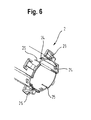
- Fig. 6 shows a perspective view of a switch handle receptacle 2.
- the switch handle receptacle 2 with its substantially cup-shaped base body has recesses 24 and grooves 25 for receiving the stop ring 10 on its end face.
- the switch handle receptacle 2 has fastening elements 26 in the form of snap hooks for fastening the switch handle receptacle 2 to the strip carrier.
Landscapes
- Physics & Mathematics (AREA)
- General Physics & Mathematics (AREA)
- Engineering & Computer Science (AREA)
- Automation & Control Theory (AREA)
- Cookers (AREA)
Description
- Die Erfindung bezieht sich auf eine Schaltvorrichtung für ein Gargerät sowie ein Haushaltsgerät, insbesondere ein Gargerät mit einer Schaltvorrichtung.
- Schaltvorrichtungen, auch als Versenkknebel bezeichnet, dienen in einer Betätigungsstellung mittels einer Drehbewegung der manuellen Einstellung von Betriebsparametern, wie z. B. der Temperatur- oder der Betriebsart. In der Ruhestellung, also bei Nichtgebrauch, ist die Schaltvorrichtung in einer Bedienblende der Gargerätefront flächenbündig versenkbar. Durch leichten Druck auf die versenkte Schaltvorrichtung bewegt sich die Schaltvorrichtung mittels Federkraft selbständig über die Bedienblende hinaus. Die Entriegelung d. h. das Herausfahren der Schaltvorrichtung in die Betätigungsstellung erfolgt durch die auf die Achse der Schaltvorrichtung wirkende Federkraft.
- Der folgenden Erfindung liegt die Aufgabe zugrunde, den Bedienkomfort einer Schaltvorrichtung der eingangs genannten Art zu verbessern.
- Diese Aufgabe wird durch eine Schaltvorrichtung für ein Gargerät gelöst, welche mit einer Schaltergriffaufnahme zur Aufnahme einer versenkbaren Achshülse ausgestattet ist, welche über eine Schaltergriffführung geführt und über einen Achsdorn drehbar gelagert ist. Dabei befindet sich an der Schaltergriffaufnahme ein Anschlagring, der in einer Betätigungsstellung der Schaltvorrichtung einen Endanschlag für die Achshülse bildet. Dieser Aufbau der Schaltvorrichtung erzeugt eine Baugruppe, die an - aus Benutzersicht - Rückseite der Bedienblende der Gerätefront derart befestigt ist, dass die Achshülse durch eine bedienblendenseitige Aussparung in Richtung Benutzer ausfährt. Zugleich ist eine Schaltergriffkappe abziehbar auf der Achshülse gelagert. In dieser Betriebsstellung ist die Achshülse derart am Anschlagring positioniert, dass ein Kippen bzw. ein Spiel der Schaltergriffkappe in der Schaltvorrichtung verhindert wird.
- Vorzugsweise weist der Anschlagring und/oder die Achshülse zumindest abschnittsweise Anschlagflächen zur Verringerung der Reibung zwischen Anschlagring und Achshülse auf. Diese Reibung entsteht durch die in der Schaltvorrichtung wirkende Federkraft um die Schaltvorrichtung in Betätigungsstellung zu bringen. In der Betätigungsstellung liegt ein scheibenförmig an der Achshülse angeordneter Kragen plan an der Anschlagfläche des Anschlagrings auf und erzeugt die für den Benutzer ungewünschte Reibkraft. Um die Auflagefläche der Achshülse zum Endanschlag zu minimieren, werden abschnittsweise Erhöhungen oder Aussparungen an den Kontaktflächen angebracht. Die Anschlagflächen sind dabei geometrisch so geformt, dass sie in Werkzeugen einfach zu entformen sind und zugleich verschleißarm sind. Als Geometrie bieten sich u.a. kugelförmige oder pyramidenstumpfförmige Anschlagflächen. Zudem ist die Materialwahl der beiden Bauteile in derart aufeinander abgestimmt, dass die Reibkraft minimiert ist.
- Vorzugsweise weist der Anschlagring Mittel zur eindeutigen formschlüssigen Positionierung in der Schaltergriffaufnahme, insbesondere durch Rasthaken und/oder Formelemente auf. Die von der Feder und der Achshülse aus dem Anschlagring wirkenden Kräfte erfordern eine gute Befestigung des Anschlagrings in der Schaltergriffaufnahme. Dazu sind in der Schaltergriffaufnahme Aussparungen vorgesehen, in welche die am Anschlagring angeordneten Rasthaken formschlüssig eintauchen. Damit der Anschlagring in der Schaltergriffaufnahme eindeutig positioniert ist und das Mitdrehen des Anschlagrings bei Drehbetätigung der Schaltvorrichtung ausgeschlossen ist, befinden sich am Anschlagring Formelemente, die in Aussparungen und Nuten der Schaltergriffaufnahme greifen und eine Sicherung gegen ungewolltes verdrehen sicherstellen.
- Vorzugsweise ist der Anschlagring derart ausgebildet, dass er eine Hohlgeometrie aufweist. Um die federnde Wirkung dieser Rasthaken zu unterstützen, ist der Anschlagring nicht aus einem Vollmaterial hergestellt, sondern weist eine Hohlgeometrie auf, die im Querschnitt gesehen im Wesentlichen U-förmig ausgebildet ist und an einem Schenkel den Rasthaken aufnimmt, welcher somit federnd gegenüber dem zweiten Schenkel des U-förmigen Anschlagrings ausgebildet ist und besser in die Aussparungen der Schaltergriffaufnahme eintaucht.
- Vorzugsweise ist an der Achshülse zumindest ein Schnapphaken vorgesehen der die Schaltergriffkappe aufnimmt. Dabei weist der Schnapphaken einen Abschnitt auf, der dazu ausgebildet ist, form- und kraftschlüssig in eine Rillenstruktur der Schaltergriffkappe einzugreifen. Dadurch wird ein Abnehmen der Schaltergriffkappe von der Achshülse ermöglicht, ohne die Schaltergriffaufnahme von der Bedienblende der Gargerätefront zu demontieren. Eine somit vom Benutzer abziehbare Schaltergriffkappe verringert den Aufwand beim Tausch der Schaltergriffkappe erheblich. Solch ein Tausch kann notwendig sein, wenn die Kappe defekt oder verschmutzt ist, oder der Benutzer eine Schaltergriffkappe mit einem anderen Design wünscht.
- Vorzugsweise weist die Rillenstruktur zumindest eine Raste, vorzugsweise drei Rasten auf. Die Rasten des Schnapphakens, welche form- und kraftschlüssig mit der Rillenstruktur der Schaltergriffkappe in Wirkverbindung stehen, sind für die lösbare Verbindung der Schaltergriffkappe an der Achshülse verantwortlich. Greift der Benutzer die Schaltergriffkappe und zieht an dieser mit einer Kraft F, welche die Haltekraft des Schnapphakens übersteigt, löst sich die Schaltergriffkappe von der Achshülse. Dabei wird die Raste der Rillenstruktur des Schnapphakens aus der Rillenstruktur der Schaltergriffkappe gelöst und die Schaltergriffkappe wird freigegeben. Gemäß einer Variante befinden sich in der Schaltergriffkappe mehrere Rillen, in welche die Raste des Schnapphakens nacheinander eingreift bevor die Schaltergriffkappe endgültig abgezogen. Dies erhöht die Sicherheit, z. B. gegen unbeabsichtigtes Abziehen. Gemäß einer Variante weist die Rillenstruktur des Schnapphakens mehrere Rasten auf, welche in mehrere Rillen der Rillenstruktur der Schaltergriffkappe eintauchen. Diese Ausführung gewährleistet, dass die Rillenstruktur des Schnapphakens bei einer ungedämpften Ausfahrbewegung und damit verbundenen schlagartigen Stoppen am Anschlagring lediglich in die nächstfolgende Rille der Schaltergriffkappe greift und die Schaltergriffkappe nicht sofort frei gibt.
- Vorzugsweise weist der Schnapphaken zumindest eine Aussparung auf. Konstruktiv entsteht ein guter Schnapphaken, wenn der Sockel des Schnapphakens möglichst breit ausgeführt ist, um die Drehmomentübertragung des Benutzers zur Werteverstellung von der Schaltergriffkappe auf die Achshülse sicherzustellen. Solch ein breiter Sockel steht jedoch im Konflikt mit der Flexibilität und federnden Wirkung der Schnapphaken. Dies wird mit einer Aussparung oder einem Schlitz im Schnapphaken gelöst. Durch diese Form ist der Schnapphaken in zumindest zwei Bereiche unterteilt, um die Federkraft zum Trennen der Schaltergriffkappe von der Achshülse zu verringern.
- Vorzugsweise ist an der Achshülse ein Rotationsdämpfer vorgesehen, welcher die Achshülse auf ihrem Weg von der Ruhestellung in Richtung der Betätigungsstellung dämpft. Der auf der Achshülse angebrachte Rotationsdämpfer, z.B. in Form eines Fettdämpfers, greift in eine Zahnstange der Schaltergriffführung.
- Vorzugsweise ist die Schaltergriffkappe abnehmbar ausgebildet und weist eine Rillenstruktur zur form- und kraftschlüssigen Wirkverbindung mit der Rillenstruktur des Schnapphakens an der Achshülse auf. Vorzugsweise ist diese Rillenstruktur auf der inneren Mantelfläche der Schaltergriffkappe angeordnet.
- Vorzugsweise weist die Schaltergriffaufnahme Aussparungen und/oder Nuten zur Aufnahme des Anschlagrings auf. Mittels dieser Aussparungen und/oder Nuten wird der Anschlagring über seine Rasthaken und Formelemente kraft- und formschlüssig an die Schaltergriffaufnahme angebunden.
- Vorzugsweise weist die Schaltergriffaufnahme Befestigungselemente zur Befestigung am Blendenträger auf. Aus dem Blendenträger werden zumeist U-förmige Laschen ausgeprägt, in welche die Befestigungselemente der Schaltergriffaufnahme eingreifen.
- Vorzugsweise ist die Baugruppe aus Achsdorn und Schaltergriffaufnahme durch ein "2-Komponenten-Verfahren" gebildet. Durch das "2-Komponenten-Verfahren" wird ein zuvor hergestellter Achsdorn von der Schaltergriffaufnahme kunststofftechnisch umspritzt. So nimmt der Achsdorn die Schaltergriffführung drehbar in der Schaltergriffaufnahme auf. Zudem weist der Achsdorn einer Kupplungsgeometrie auf, welche eine Schnittstelle zur Verbindung mit den elektronischen Anbauteilen ist.
- Weitere Merkmale der Erfindung ergeben sich aus den Ansprüchen, den Figuren und der Figurenbeschreibung. Die vorgehend in der Beschreibung genannten Merkmale und Merkmalskombinationen sowie die nachfolgend in der Figurenbeschreibung genannten und/oder in den Figuren alleine gezeigten Merkmale und Merkmalskombinationen sind nicht nur in der jeweils angegebenen Kombination, sondern auch in anderen Kombinationen oder in Alleinstellung verwendbar, ohne den Rahmen der Erfindung zu verlassen. Es sind somit auch Ausführungen von der Erfindung als umfasst und offenbart anzusehen, die in den Figuren nicht explizit gezeigt und erläutert sind, jedoch durch separierte Merkmalskombinationen aus den erläuterten Ausführungen hervorgehen und erzeugbar sind.
- Weitere Vorteile und Einzelheiten der Erfindung werden anhand der in den schematischen Figuren dargestellten Ausführungsbeispiele näher erläutert. Dabei zeigt
- Fig. 1
- eine schematisch perspektivische Darstellung einer Schaltvorrichtung für ein Gargerät;
- Fig. 2
- eine erste schematische perspektivische Darstellung eines Anschlagrings;
- Fig. 3
- eine zweite schematische perspektivische Darstellung eines Anschlagrings;
- Fig. 4
- eine schematische perspektivische Darstellung einer Achshülse;
- Fig. 5
- eine schematisch perspektivische Darstellung einer Schaltergriffkappe; und
- Fig. 6
- eine schematische perspektivische Darstellung einer Schaltergriffaufnahme.
- In den Figuren werden gleiche oder funktionsgleiche Elemente mit den gleichen Bezugszeichen versehen.
- In
Fig. 1 ist in einer perspektivischen Darstellung eine Schaltvorrichtung für ein Gargerät gezeigt. Die Schaltvorrichtung 1 ist an der Gerätefront im Bereich des Bedienabschnitts in der Art angebracht, dass ein Benutzer zur Verstellung sogenannter Betriebsparameter, wie z. B. Betriebsart oder Temperatur, die Schaltvorrichtung 1 greift und durch drehen verstellt. Die Schaltvorrichtung 1 weist dazu eine Mehrzahl von Bauteilen auf, welche zu einer Baugruppe gefügt sind. Als Gehäuse und somit als tragendes Element der Schaltvorrichtung 1 ist die Schaltergriffaufnahme 2 ausgebildet. Die Schaltergriffaufnahme 2 stellt im Wesentlichen ein topfförmiges Element dar, in dessen Topfboden ein Achsdorn 3 zentral angeordnet ist. Dieser Achsdorn 3 ist über ein 2-Komponenten-Verfahren in eine Aussparung im Boden der Schaltergriffaufnahme 2 kunststofftechnisch eingespritzt. Der Achsdorn 3 stellt im Wesentlichen einen rotationssymmetrischen Körper dar, an dessen breiter Basis die Befestigung zur Schaltergriffaufnahme gebildet ist. Dieser Bereich stellt auch eine Schnittstelle zur Verbindung mit den elektronischen Anbauteilen dar, wobei die Schnittstelle im Wesentlichen schlitzförmig ausgebildet ist und durch die bodenseitige Aussparung der Schaltergriffaufnahme 2 rückseitig aus der Schaltergriffaufnahme 2 ragt. Innerhalb des Schaltergriffaufnahme 2 bildet der Achsdorn 3 mit seinem im Wesentlichen rotationssymmetrischen Schaft eine Achse Y, um welche sich die wesentlichen Bauteile der Schaltvorrichtung 1 zur Werteverstellung drehen. Über eine Mitnahmefläche des Achsdorns 3 ist die Schaltergriffführung 5 rotatorisch in der Schaltergriffaufnahme geführt und mittels einer Blattfeder 4 gegen Auszug gesichert. Die Schaltergriffführung 5 stellt ein längliches Bauteil dar, dass die Achshülse 6 versenkbar aufnimmt. Dazu ist der hülsenförmige Grundkörper der Achshülse 6 auf den Außenumfang der Schaltergriffführung 5 angepasst. Die Schaltergriffführung 5 weist dazu eine kulissenförmige Herzkurve auf, die für ein gleichmäßiges, ruckelfreies Versenken der Achshülse 6 und dessen Sicherung in der Ruhelage und dient. Dazu stützt sich an der Schaltergriffführung 5 eine Spiralfeder ab und erzeugt eine Federkraft gegenüber der Achshülse 6, so dass diese bestrebt ist, aus der Ruhestellung in der Schaltergriffaufnahme 2 in die Betriebslage zu gleiten. Um diese Federkraft zu dämpfen, Beschädigungen zu vermeiden sowie dem Benutzer ein hochwertiges Empfinden zu vermitteln, befindet sich auf der Achshülse 6 ein Rotationsdämpfer 8, welcher mit einem Zahnrad in eine Zahnstange der Schaltergriffführung 5 eingreift somit die Achshülse 6 gedämpft und gleichmäßig ausfahren lässt. Auf der Achshülse 6 befindet sich eine Schaltergriffkappe 9, welche in Betriebsstellung den im Wesentlichen sichtbaren Bereich der Schaltvorrichtung 1 entspricht, die dem Benutzer aus der Gerätefront entgegensteht. Dieser Aufbau der Schaltvorrichtung 1 ermöglicht es der Achshülse 6 zwischen zwei Positionen zu verfahren. Die erste Position, im Folgenden als eingefahrener Ruhezustand beschrieben, nimmt die Achshülse 6 und die Schaltergriffkappe 9 im Wesentlichen in der Schaltergriffaufnahme 2 auf. Befindet sich die Achshülse 6 in der eingefahrenen Ruhestellung, so erzeugt ein Drücken des Benutzers auf die Schaltergriffkappe 9, dass die Herzkulisse die Achshülse 6 entriegelt und die Spiralfeder 7, die Achshülse in Y-Richtung aus der Schaltergriffaufnahme 2 drückt. Ein Anschlagring 10 definiert die ausgefahrene Betriebsstellung, da ein scheibenförmig ausgebildeter Kragen der Achshülse 6 an der Anschlagfläche 11 des Anschlagrings 10 stoppt. Dieser Aufbau ermöglicht das Versenken der Schaltergriffkappe 9 in der Schaltergriffaufnahme 2 und zugleich eine Werteverstellung durch die drehbar gelagerte Schaltergriffkappe 9. Diese gibt die Drehbewegung über die Achshülse 6 an die Schaltergriffführung 5 und den sich mitdrehenden Achsdorn 3 weiter. Die Schnittstelle des Achsdorns überträgt die Drehbewegung an die angrenzenden elektronischen Bauteile. -
Fig. 2 zeigt eine perspektivische Ansicht eines Anschlagrings. Der im Wesentlichen ringförmige Grundkörper weist an seiner ersten Stirnfläche 12 kugelförmige Anschlagflächen 11 zur Verringerung der Reibung mit der Anschlaghülse 6 auf. Diese Anschlagflächen 11 beabstanden die kragenförmige Anschlagfläche der Achshülse 6. An der Mantelfläche 13 des Anschlagrings 10 befinden sich Rasthaken zur Befestigung des Anschlagrings 10 in der Schaltergriffaufnahme 2. Des Weiteren befinden sich auf der Mantelfläche 13 Formelemente 15, welche in die Schaltergriffaufnahme 2 eingreifen. Diese Formelemente 15 stellen die richtige Einbaulage des Anschlagrings 10 in der Schaltergriffaufnahme 2 sicher und befestigen den Anschlagring 10 gegenüber den wirkenden rotatorischen Reibkräften, welche bei der Werteverstellung wirken. -
Fig. 3 zeigt in einer perspektivischen Darstellung die Rückansicht des Anschlagrings 10. Der ringförmige Grundkörper des Anschlagrings 10 weist dabei auf der der Stirnfläche 12 gegenüberliegenden Stirnfläche eine umlaufende Nut 16 auf, welche den Anschlagring 10 mit einer Hohlgeometrie ausstattet. Dadurch weist der ringförmige Grundkörpers einen im Wesentlichen U-förmigen Querschnitt auf, dessen erster Schenkel die Anlagefläche für die Schaltergriffkappe 9 bildet und dessen zweiter Schenkel die Rasthaken 14 und die Formelemente 15 aufnimmt. Durch diesen federnden Schenkel tauchen die Rasthaken 14 und die Formelemente 15 form- und kraftschlüssig in die Aussparungen 24 der Schaltergriffaufnahme 2 ein. Die Basis des im Wesentlichen U-förmigen Querschnitts trägt die im Wesentlichen kugelförmigen Anschlagflächen 11 zur Verringerung der bei Drehbewegung zwischen Achshülse 6 und Anschlagring 10 wirkenden Reibkräfte. -
Fig. 4 zeigt in einer perspektivischen Darstellung eine Achshülse 6. Die Achshülse 6 weist an einem ersten Ende eine Kupplungsgeometrie zur Anbindung an die Schaltergriffführung 5 auf, an der sich auch der Rotationsdämpfer 8 befindet. In einem zweiten Abschnitt befindet sich ein im Wesentlichen scheibenförmig angebachter Kragen 17, der eine ringförmige Anschlagfläche zum Anschlagring 10 aufweist. Zur Versteifung ist dieser Kragen 17 mit Rippen ausgestattet. Stirnseitig erstrecken sich aus der scheibenförmigen Fläche des Kragens 17 vorzugsweise drei asymmetrisch angeordnete Schnapphaken 18, welche zur Befestigung der Schaltergriffkappe 9 und zur Drehmomentübertragung der Werteverstellung von der Schaltergriffkappe 9 auf die Achshülse 6 ausgebildet sind. Die Schnapphaken 18 weisen eine Rillenstruktur 19 zum Eingriff in eine korrespondierende Rillenstruktur 23 in der Schaltergriffkappe 9 auf. Die Rillenstruktur 19 ist dabei von drei Rasten 20 gebildet, welche in eine Mehrzahl an Rillen der Rillenstruktur 23 eingreifen, so dass bei übermäßiger Zugkraft des Benutzers an der Schaltergriffkappe 9 die Kappe nicht sofort freigegeben wird, sondern die Rasten 20 lediglich in die nächstliegenden Rillen der Rillenstruktur 23 greifen. Zudem wird durch diesen Aufbau vermieden, dass sich beim sog. Ausschnalzen der Schaltvorrichtung 1 die Schaltergriffkappe 9 von der Achshülse 6 ungewünschter weise löst. Zudem weist der Schnapphaken 18 eine Aussparung in Form eines Schlitzes auf, um den Schnapphaken 18 in seiner federnden Funktionsweise zur Aufnahme der Schaltergrifföffnung 9 zu unterstützen. Durch die Aussparung des Schnapphakens 18 entstehen zwei Fortsätze, welche sich flexibler bewegen lassen als die nicht geschlitzte Basis des Schapphakens 18. Durch die Flexibilität des Schnapphakens 18 wird der form- und kraftschlüssige Verbindungsmechanismus zwischen Achshülse 6 und Schaltergriffkappe 9 verbessert. -
Fig. 5 zeigt eine perspektivische Darstellung einer Schaltergriffkappe 9. Die im Wesentlichen topfförmige Schaltergriffkappe 9 weist an ihrer innenliegenden Mantelfläche 22 eine Rillenstruktur 23 zur Verbindung mit dem Schapphaken 18 der Achshülse 6 auf. Dabei greifen die Rasten 20 des Schnapphakens 18 in die Rillenstruktur 23 ein und bewirken durch die federnde Wirkung des Schnapphakens 18 eine form- und kraftschlüssige Verbindung, welche das Drehmoment der Werteverstellung auf die Achshülse 6 sicher übertragt und gleichzeitig eine Sicherung der Schaltergriffkappe 9 gegen ungewolltes Abziehen sicherstellt. Die mehrteilige Rillenstruktur vermittelt zudem dem Benutzer, welcher die Schaltergriffkappe 9 bewusst abziehen möchte, ein taktiles Feedback, da sich in einem ersten Schritt lediglich eine Raste 20 aus der Rillenstruktur 23 bewegt. Daraus kann der Benutzer abschätzen, dass sich die Schaltergriffkappe 9 bei gleichbleibendem Kraftaufwand lässt und eine weitere Erhöhung des Kraftaufwands nicht von Nöten ist. Bei ungedämpften Schaltvorrichtungen 1 ist die Rillenstruktur 23 zudem von Vorteil, da das Schnalzen gegen den Endanschlag nicht das komplette Lösen der Schaltergriffkappe 9 von der Achshülse 6 bewirkt, sondern lediglich das die Rasten 20 in eine weiter außen liegende Rille der Rillenstruktur 23 eingreifen. Die Rillenstruktur 23 in der Schaltergriffkappe 9 kann umlaufend oder abschnittsweise angeordnet sein. Die Rillenstruktur 23 kann - nach Art einer Gewindemutter - aus einer gewindeförmigen, spiralartigen Rillenanordnung an der Mantelfläche 22 ausgebildet sein. -
Fig. 6 zeigt eine perspektivische Darstellung einer Schaltergriffaufnahme 2. Die Schaltergriffaufnahme 2, mit ihrem im Wesentlichen topfförmigen Grundkörper weist an ihrer Stirnfläche Aussparungen 24 und Nuten 25 zur Aufnahme des Anschlagsrings 10 auf. Zudem weist die Schaltergriffaufnahme 2 Befestigungselemente 26 in Form von Schnapphaken zur Befestigung der Schaltergriffaufnahme 2 am Bendenträger auf. -
- 1
- Schaltvorrichtung
- 2
- Schaltergriffaufnahme
- 3
- Achsdorn
- 4
- Blattfeder
- 5
- Schaltergriffführung
- 6
- Achshülse
- 7
- Spiralfeder
- 8
- Rotationsdämpfer
- 9
- Schaltergriffkappe
- 10
- Anschlagring
- 11
- Anschlagfläche
- 12
- Stirnfläche
- 13
- Mantelfläche
- 14
- Rasthaken
- 15
- Formelement
- 16
- Nut
- 17
- Kragen
- 18
- Schnapphaken
- 19
- Rillenstruktur
- 20
- Raste
- 21
- Aussparung
- 22
- Mantelfläche
- 23
- Rillenstruktur
- 24
- Aussparung
- 25
- Nut
- 26
- Befestigungselement
Claims (13)
- Schaltvorrichtung (1) für ein Gargerät, mit einer Schaltergriffaufnahme (2) zur Aufnahme einer versenkbaren Achshülse (6), welche über eine Schaltergriffführung (5) geführt und über einen Achsdorn (3) drehbar gelagert ist, wobei ein an der Schaltergriffaufnahme (2) angeordneter Anschlagring (10) vorgesehen ist, der in einer Betätigungsstellung der Schaltvorrichtung (1) einen Anschlag für die Achshülse (6) bildet.
- Schaltvorrichtung nach Anspruch 1, dadurch gekennzeichnet, dass der Anschlagring (10) und/oder die Achshülse (6) zumindest abschnittsweise Anschlagflächen (11) zur Verringerung der Reibung zwischen Anschlagring (10) und Achshülse (6) aufweisen.
- Schaltvorrichtung (1) nach einem der vorhergehenden Ansprüche, dadurch gekennzeichnet, dass der Anschlagring (10) Mittel zur eindeutigen formschlüssigen Positionierung in der Schaltergriffaufnahme (2), insbesondere Rasthaken (14) und/oder Formelemente (15) aufweist.
- Schaltvorrichtung (1) nach einem der vorhergehenden Ansprüche, dadurch gekennzeichnet, dass der Anschlagring (10) eine Hohlgeometrie zum Verrasten der Rasthaken (14) aufweist.
- Schaltvorrichtung (1) nach einem der vorhergehenden Ansprüche, dadurch gekennzeichnet, dass an der Achshülse (6) zumindest ein Schnapphaken (18) vorgesehen ist, welcher form- und kraftschlüssig in eine Rillenstruktur (23) einer Schaltergriffkappe (9) eingreift, wodurch die Schaltergriffkappe (9) abnehmbar ausgeführt ist.
- Schaltvorrichtung (1) nach einem der vorhergehenden Ansprüche, dadurch gekennzeichnet, dass der Schnapphaken (18) zumindest eine Raste (20), vorzugsweise drei Rasten aufweist.
- Schaltvorrichtung (1) nach einem der vorhergehenden Ansprüche, dadurch gekennzeichnet, dass der Schnapphaken (18) zumindest eine Aussparung (21) aufweist, wodurch der Schnapphaken (18) in zumindest zwei Bereiche unterteilt ist, und die Federkraft zum Trennen der Schaltergriffkappe (9) und der Achshülse (6) verringerbar ist.
- Schaltvorrichtung (1) nach einem der vorhergehenden Ansprüche, dadurch gekennzeichnet, dass an der Achshülse (6) ein Rotationsdämpfer (8) vorgesehen ist, welcher die Achshülse (6) in Richtung der Betätigungsstellung dämpft.
- Schaltvorrichtung (1) nach einem der vorhergehenden Ansprüche, dadurch gekennzeichnet, dass die Schaltergriffkappe (9) abnehmbar ausgebildet ist, und eine Rillenstruktur (23) zur form- und kraftschlüssigen Verbindung mit der Achshülse (6) aufweist.
- Schaltvorrichtung (1) nach einem der vorhergehenden Ansprüche, dadurch gekennzeichnet, dass die Schaltergriffaufnahme (2) Aussparungen (24) und/oder Nuten (25) zur Aufnahme des Anschlagrings (10) aufweist.
- Schaltvorrichtung (1) nach einem der vorhergehenden Ansprüche, dadurch gekennzeichnet, dass die Schaltergriffaufnahme (2) Befestigungselemente (26) zur Befestigung am Blendenträger aufweist.
- Schaltvorrichtung (1) nach einem der vorhergehenden Ansprüche, dadurch gekennzeichnet, dass die Baugruppe aus Achsdorn (3) und Schaltergriffaufnahme (2) durch ein 2-Komponenten-Verfahren gebildet ist.
- Haushaltsgerät, insbesondere Gargerät, mit einer Schaltvorrichtung (1) nach einem der vorhergehenden Ansprüche.
Priority Applications (1)
| Application Number | Priority Date | Filing Date | Title |
|---|---|---|---|
| PL14177422T PL2835711T3 (pl) | 2013-07-30 | 2014-07-17 | Urządzenie przełączeniowe do urządzenia do gotowania |
Applications Claiming Priority (1)
| Application Number | Priority Date | Filing Date | Title |
|---|---|---|---|
| DE102013214849.6A DE102013214849A1 (de) | 2013-07-30 | 2013-07-30 | Schaltvorrichtung für ein Gargerät |
Publications (2)
| Publication Number | Publication Date |
|---|---|
| EP2835711A1 true EP2835711A1 (de) | 2015-02-11 |
| EP2835711B1 EP2835711B1 (de) | 2019-09-11 |
Family
ID=51211597
Family Applications (1)
| Application Number | Title | Priority Date | Filing Date |
|---|---|---|---|
| EP14177422.4A Active EP2835711B1 (de) | 2013-07-30 | 2014-07-17 | Schaltvorrichtung für ein gargerät |
Country Status (3)
| Country | Link |
|---|---|
| EP (1) | EP2835711B1 (de) |
| DE (1) | DE102013214849A1 (de) |
| PL (1) | PL2835711T3 (de) |
Cited By (1)
| Publication number | Priority date | Publication date | Assignee | Title |
|---|---|---|---|---|
| DE102024108388A1 (de) * | 2024-03-25 | 2025-09-25 | Hansgrohe Se | Bediengriffvorrichtung für ein Thermostatventil und Wandeinbauvorrichtung |
Citations (4)
| Publication number | Priority date | Publication date | Assignee | Title |
|---|---|---|---|---|
| GB2236380A (en) * | 1989-09-25 | 1991-04-03 | Toshiba Kk | Retractable operating knobs for washing machines |
| EP1486998A1 (de) * | 2002-12-17 | 2004-12-15 | Matsushita Electric Industrial Co., Ltd. | Eingabeeinrichtung |
| EP2410547A1 (de) * | 2010-07-22 | 2012-01-25 | Miele & Cie. KG | Haushaltgerät mit versenkbarer Bedienknebeleinheit |
| DE102012222146A1 (de) * | 2012-12-04 | 2014-06-18 | BSH Bosch und Siemens Hausgeräte GmbH | Bedienelement für ein Haushaltsgerät mit einem Stützelement und einem Führungselement, Bedienvorrichtung mit einem derartigen Bedienelement sowie Haushaltsgerät mit einer Bedienvorrichtung |
Family Cites Families (2)
| Publication number | Priority date | Publication date | Assignee | Title |
|---|---|---|---|---|
| FR2785385B1 (fr) * | 1998-10-29 | 2001-01-19 | Valeo Electronique | Dispositif d'encodage incremental avec une fonction poussoir |
| DE19951422B4 (de) * | 1999-10-26 | 2006-04-06 | AEG Hausgeräte GmbH | Versenkbare Drehbedieneinheit |
-
2013
- 2013-07-30 DE DE102013214849.6A patent/DE102013214849A1/de not_active Ceased
-
2014
- 2014-07-17 PL PL14177422T patent/PL2835711T3/pl unknown
- 2014-07-17 EP EP14177422.4A patent/EP2835711B1/de active Active
Patent Citations (4)
| Publication number | Priority date | Publication date | Assignee | Title |
|---|---|---|---|---|
| GB2236380A (en) * | 1989-09-25 | 1991-04-03 | Toshiba Kk | Retractable operating knobs for washing machines |
| EP1486998A1 (de) * | 2002-12-17 | 2004-12-15 | Matsushita Electric Industrial Co., Ltd. | Eingabeeinrichtung |
| EP2410547A1 (de) * | 2010-07-22 | 2012-01-25 | Miele & Cie. KG | Haushaltgerät mit versenkbarer Bedienknebeleinheit |
| DE102012222146A1 (de) * | 2012-12-04 | 2014-06-18 | BSH Bosch und Siemens Hausgeräte GmbH | Bedienelement für ein Haushaltsgerät mit einem Stützelement und einem Führungselement, Bedienvorrichtung mit einem derartigen Bedienelement sowie Haushaltsgerät mit einer Bedienvorrichtung |
Cited By (2)
| Publication number | Priority date | Publication date | Assignee | Title |
|---|---|---|---|---|
| DE102024108388A1 (de) * | 2024-03-25 | 2025-09-25 | Hansgrohe Se | Bediengriffvorrichtung für ein Thermostatventil und Wandeinbauvorrichtung |
| EP4628769A1 (de) | 2024-03-25 | 2025-10-08 | Hansgrohe SE | Bediengriffvorrichtung für ein thermostatventil und wandeinbauvorrichtung |
Also Published As
| Publication number | Publication date |
|---|---|
| EP2835711B1 (de) | 2019-09-11 |
| DE102013214849A1 (de) | 2015-02-05 |
| PL2835711T3 (pl) | 2020-06-15 |
Similar Documents
| Publication | Publication Date | Title |
|---|---|---|
| DE102010015064B4 (de) | Feststeller für eine Fahrzeugtür oder -klappe | |
| EP0293580A2 (de) | Raspel- oder Schneidwerkzeugsanordnung zum Zerkleinern von Nahrungsmitteln, insbesondere für Küchenmaschinen | |
| DE10332297A1 (de) | Gehäuse | |
| DE202006017553U1 (de) | Kinderhochstuhl | |
| EP3180527B1 (de) | Befestigungsvorrichtung und befestigungsanordnung, insbesondere zur befestigung eines sanitärobjekts | |
| EP2924195A1 (de) | Anschlagkörper für Tür- und/oder Fenstergriffe und Griffanordnung mit einem Anschlagkörper | |
| EP2985477A1 (de) | Befestigungsvorrichtung und befestigungsanordnung, insbesondere zur befestigung eines sanitärobjekts | |
| DE19746509A1 (de) | Kochgefäß | |
| EP0460297B1 (de) | Betätigungshandhabe | |
| EP3434514B1 (de) | Getränkehalter | |
| DE102008028086A1 (de) | Ablaufsicherung sowie Verstellbeschlag | |
| EP2835711B1 (de) | Schaltvorrichtung für ein gargerät | |
| DE202015104446U1 (de) | Laborrührer | |
| DE4417485C2 (de) | Sanitärarmatur | |
| DE102008020986A1 (de) | Vorrichtung mit einem Unterteil und einer Rückholfeder zur drehbaren Lagerung eines Ausstattungsteils, insbesondere eines Türdrückers | |
| EP3287054B1 (de) | Verbindungsvorrichtung zum ankuppeln einer aufsatzeinrichtung an eine küchenmaschine | |
| DE19541214C1 (de) | Drehbetätigungseinrichtung | |
| EP1882798A1 (de) | Tür- oder Fensterbeschlag | |
| DE202020100426U1 (de) | Zug-Druck-Stange | |
| DE1665800B2 (de) | Drehschalterantrieb | |
| DE3341180C2 (de) | Haushaltsschneidemaschine, insbesondere mit elektromotorischem Antrieb | |
| WO1994003912A1 (de) | Schalter für elektrisch angetriebene geräte | |
| DE602004000592T2 (de) | Verbindungsvorrichtung für ein Steuerkabelende | |
| DE7709636U1 (de) | Betaetigungs-handhabe | |
| DE4440554B4 (de) | Paketnockenschalter |
Legal Events
| Date | Code | Title | Description |
|---|---|---|---|
| PUAI | Public reference made under article 153(3) epc to a published international application that has entered the european phase |
Free format text: ORIGINAL CODE: 0009012 |
|
| 17P | Request for examination filed |
Effective date: 20140717 |
|
| AK | Designated contracting states |
Kind code of ref document: A1 Designated state(s): AL AT BE BG CH CY CZ DE DK EE ES FI FR GB GR HR HU IE IS IT LI LT LU LV MC MK MT NL NO PL PT RO RS SE SI SK SM TR |
|
| AX | Request for extension of the european patent |
Extension state: BA ME |
|
| RAP1 | Party data changed (applicant data changed or rights of an application transferred) |
Owner name: BSH HAUSGERAETE GMBH |
|
| R17P | Request for examination filed (corrected) |
Effective date: 20150811 |
|
| RBV | Designated contracting states (corrected) |
Designated state(s): AL AT BE BG CH CY CZ DE DK EE ES FI FR GB GR HR HU IE IS IT LI LT LU LV MC MK MT NL NO PL PT RO RS SE SI SK SM TR |
|
| GRAP | Despatch of communication of intention to grant a patent |
Free format text: ORIGINAL CODE: EPIDOSNIGR1 |
|
| STAA | Information on the status of an ep patent application or granted ep patent |
Free format text: STATUS: GRANT OF PATENT IS INTENDED |
|
| INTG | Intention to grant announced |
Effective date: 20190408 |
|
| GRAS | Grant fee paid |
Free format text: ORIGINAL CODE: EPIDOSNIGR3 |
|
| GRAA | (expected) grant |
Free format text: ORIGINAL CODE: 0009210 |
|
| STAA | Information on the status of an ep patent application or granted ep patent |
Free format text: STATUS: THE PATENT HAS BEEN GRANTED |
|
| AK | Designated contracting states |
Kind code of ref document: B1 Designated state(s): AL AT BE BG CH CY CZ DE DK EE ES FI FR GB GR HR HU IE IS IT LI LT LU LV MC MK MT NL NO PL PT RO RS SE SI SK SM TR |
|
| REG | Reference to a national code |
Ref country code: GB Ref legal event code: FG4D Free format text: NOT ENGLISH |
|
| REG | Reference to a national code |
Ref country code: CH Ref legal event code: EP |
|
| REG | Reference to a national code |
Ref country code: AT Ref legal event code: REF Ref document number: 1179270 Country of ref document: AT Kind code of ref document: T Effective date: 20190915 |
|
| REG | Reference to a national code |
Ref country code: DE Ref legal event code: R096 Ref document number: 502014012610 Country of ref document: DE Ref country code: IE Ref legal event code: FG4D Free format text: LANGUAGE OF EP DOCUMENT: GERMAN |
|
| REG | Reference to a national code |
Ref country code: NL Ref legal event code: MP Effective date: 20190911 |
|
| REG | Reference to a national code |
Ref country code: LT Ref legal event code: MG4D |
|
| PG25 | Lapsed in a contracting state [announced via postgrant information from national office to epo] |
Ref country code: LT Free format text: LAPSE BECAUSE OF FAILURE TO SUBMIT A TRANSLATION OF THE DESCRIPTION OR TO PAY THE FEE WITHIN THE PRESCRIBED TIME-LIMIT Effective date: 20190911 Ref country code: FI Free format text: LAPSE BECAUSE OF FAILURE TO SUBMIT A TRANSLATION OF THE DESCRIPTION OR TO PAY THE FEE WITHIN THE PRESCRIBED TIME-LIMIT Effective date: 20190911 Ref country code: NO Free format text: LAPSE BECAUSE OF FAILURE TO SUBMIT A TRANSLATION OF THE DESCRIPTION OR TO PAY THE FEE WITHIN THE PRESCRIBED TIME-LIMIT Effective date: 20191211 Ref country code: BG Free format text: LAPSE BECAUSE OF FAILURE TO SUBMIT A TRANSLATION OF THE DESCRIPTION OR TO PAY THE FEE WITHIN THE PRESCRIBED TIME-LIMIT Effective date: 20191211 Ref country code: SE Free format text: LAPSE BECAUSE OF FAILURE TO SUBMIT A TRANSLATION OF THE DESCRIPTION OR TO PAY THE FEE WITHIN THE PRESCRIBED TIME-LIMIT Effective date: 20190911 Ref country code: HR Free format text: LAPSE BECAUSE OF FAILURE TO SUBMIT A TRANSLATION OF THE DESCRIPTION OR TO PAY THE FEE WITHIN THE PRESCRIBED TIME-LIMIT Effective date: 20190911 |
|
| PG25 | Lapsed in a contracting state [announced via postgrant information from national office to epo] |
Ref country code: LV Free format text: LAPSE BECAUSE OF FAILURE TO SUBMIT A TRANSLATION OF THE DESCRIPTION OR TO PAY THE FEE WITHIN THE PRESCRIBED TIME-LIMIT Effective date: 20190911 Ref country code: GR Free format text: LAPSE BECAUSE OF FAILURE TO SUBMIT A TRANSLATION OF THE DESCRIPTION OR TO PAY THE FEE WITHIN THE PRESCRIBED TIME-LIMIT Effective date: 20191212 Ref country code: RS Free format text: LAPSE BECAUSE OF FAILURE TO SUBMIT A TRANSLATION OF THE DESCRIPTION OR TO PAY THE FEE WITHIN THE PRESCRIBED TIME-LIMIT Effective date: 20190911 Ref country code: AL Free format text: LAPSE BECAUSE OF FAILURE TO SUBMIT A TRANSLATION OF THE DESCRIPTION OR TO PAY THE FEE WITHIN THE PRESCRIBED TIME-LIMIT Effective date: 20190911 Ref country code: ES Free format text: LAPSE BECAUSE OF FAILURE TO SUBMIT A TRANSLATION OF THE DESCRIPTION OR TO PAY THE FEE WITHIN THE PRESCRIBED TIME-LIMIT Effective date: 20190911 |
|
| PG25 | Lapsed in a contracting state [announced via postgrant information from national office to epo] |
Ref country code: NL Free format text: LAPSE BECAUSE OF FAILURE TO SUBMIT A TRANSLATION OF THE DESCRIPTION OR TO PAY THE FEE WITHIN THE PRESCRIBED TIME-LIMIT Effective date: 20190911 Ref country code: EE Free format text: LAPSE BECAUSE OF FAILURE TO SUBMIT A TRANSLATION OF THE DESCRIPTION OR TO PAY THE FEE WITHIN THE PRESCRIBED TIME-LIMIT Effective date: 20190911 Ref country code: IT Free format text: LAPSE BECAUSE OF FAILURE TO SUBMIT A TRANSLATION OF THE DESCRIPTION OR TO PAY THE FEE WITHIN THE PRESCRIBED TIME-LIMIT Effective date: 20190911 Ref country code: PT Free format text: LAPSE BECAUSE OF FAILURE TO SUBMIT A TRANSLATION OF THE DESCRIPTION OR TO PAY THE FEE WITHIN THE PRESCRIBED TIME-LIMIT Effective date: 20200113 Ref country code: RO Free format text: LAPSE BECAUSE OF FAILURE TO SUBMIT A TRANSLATION OF THE DESCRIPTION OR TO PAY THE FEE WITHIN THE PRESCRIBED TIME-LIMIT Effective date: 20190911 |
|
| PG25 | Lapsed in a contracting state [announced via postgrant information from national office to epo] |
Ref country code: SM Free format text: LAPSE BECAUSE OF FAILURE TO SUBMIT A TRANSLATION OF THE DESCRIPTION OR TO PAY THE FEE WITHIN THE PRESCRIBED TIME-LIMIT Effective date: 20190911 Ref country code: CZ Free format text: LAPSE BECAUSE OF FAILURE TO SUBMIT A TRANSLATION OF THE DESCRIPTION OR TO PAY THE FEE WITHIN THE PRESCRIBED TIME-LIMIT Effective date: 20190911 Ref country code: IS Free format text: LAPSE BECAUSE OF FAILURE TO SUBMIT A TRANSLATION OF THE DESCRIPTION OR TO PAY THE FEE WITHIN THE PRESCRIBED TIME-LIMIT Effective date: 20200224 Ref country code: SK Free format text: LAPSE BECAUSE OF FAILURE TO SUBMIT A TRANSLATION OF THE DESCRIPTION OR TO PAY THE FEE WITHIN THE PRESCRIBED TIME-LIMIT Effective date: 20190911 |
|
| REG | Reference to a national code |
Ref country code: DE Ref legal event code: R097 Ref document number: 502014012610 Country of ref document: DE |
|
| PLBE | No opposition filed within time limit |
Free format text: ORIGINAL CODE: 0009261 |
|
| STAA | Information on the status of an ep patent application or granted ep patent |
Free format text: STATUS: NO OPPOSITION FILED WITHIN TIME LIMIT |
|
| PG2D | Information on lapse in contracting state deleted |
Ref country code: IS |
|
| PG25 | Lapsed in a contracting state [announced via postgrant information from national office to epo] |
Ref country code: DK Free format text: LAPSE BECAUSE OF FAILURE TO SUBMIT A TRANSLATION OF THE DESCRIPTION OR TO PAY THE FEE WITHIN THE PRESCRIBED TIME-LIMIT Effective date: 20190911 Ref country code: IS Free format text: LAPSE BECAUSE OF FAILURE TO SUBMIT A TRANSLATION OF THE DESCRIPTION OR TO PAY THE FEE WITHIN THE PRESCRIBED TIME-LIMIT Effective date: 20200112 |
|
| 26N | No opposition filed |
Effective date: 20200615 |
|
| PG25 | Lapsed in a contracting state [announced via postgrant information from national office to epo] |
Ref country code: SI Free format text: LAPSE BECAUSE OF FAILURE TO SUBMIT A TRANSLATION OF THE DESCRIPTION OR TO PAY THE FEE WITHIN THE PRESCRIBED TIME-LIMIT Effective date: 20190911 |
|
| PG25 | Lapsed in a contracting state [announced via postgrant information from national office to epo] |
Ref country code: MC Free format text: LAPSE BECAUSE OF FAILURE TO SUBMIT A TRANSLATION OF THE DESCRIPTION OR TO PAY THE FEE WITHIN THE PRESCRIBED TIME-LIMIT Effective date: 20190911 |
|
| REG | Reference to a national code |
Ref country code: CH Ref legal event code: PL |
|
| GBPC | Gb: european patent ceased through non-payment of renewal fee |
Effective date: 20200717 |
|
| REG | Reference to a national code |
Ref country code: BE Ref legal event code: MM Effective date: 20200731 |
|
| PG25 | Lapsed in a contracting state [announced via postgrant information from national office to epo] |
Ref country code: CH Free format text: LAPSE BECAUSE OF NON-PAYMENT OF DUE FEES Effective date: 20200731 Ref country code: GB Free format text: LAPSE BECAUSE OF NON-PAYMENT OF DUE FEES Effective date: 20200717 Ref country code: LI Free format text: LAPSE BECAUSE OF NON-PAYMENT OF DUE FEES Effective date: 20200731 Ref country code: LU Free format text: LAPSE BECAUSE OF NON-PAYMENT OF DUE FEES Effective date: 20200717 Ref country code: FR Free format text: LAPSE BECAUSE OF NON-PAYMENT OF DUE FEES Effective date: 20200731 |
|
| PG25 | Lapsed in a contracting state [announced via postgrant information from national office to epo] |
Ref country code: BE Free format text: LAPSE BECAUSE OF NON-PAYMENT OF DUE FEES Effective date: 20200731 |
|
| PG25 | Lapsed in a contracting state [announced via postgrant information from national office to epo] |
Ref country code: IE Free format text: LAPSE BECAUSE OF NON-PAYMENT OF DUE FEES Effective date: 20200717 |
|
| REG | Reference to a national code |
Ref country code: AT Ref legal event code: MM01 Ref document number: 1179270 Country of ref document: AT Kind code of ref document: T Effective date: 20200717 |
|
| PG25 | Lapsed in a contracting state [announced via postgrant information from national office to epo] |
Ref country code: AT Free format text: LAPSE BECAUSE OF NON-PAYMENT OF DUE FEES Effective date: 20200717 |
|
| PG25 | Lapsed in a contracting state [announced via postgrant information from national office to epo] |
Ref country code: MT Free format text: LAPSE BECAUSE OF FAILURE TO SUBMIT A TRANSLATION OF THE DESCRIPTION OR TO PAY THE FEE WITHIN THE PRESCRIBED TIME-LIMIT Effective date: 20190911 Ref country code: CY Free format text: LAPSE BECAUSE OF FAILURE TO SUBMIT A TRANSLATION OF THE DESCRIPTION OR TO PAY THE FEE WITHIN THE PRESCRIBED TIME-LIMIT Effective date: 20190911 |
|
| PG25 | Lapsed in a contracting state [announced via postgrant information from national office to epo] |
Ref country code: MK Free format text: LAPSE BECAUSE OF FAILURE TO SUBMIT A TRANSLATION OF THE DESCRIPTION OR TO PAY THE FEE WITHIN THE PRESCRIBED TIME-LIMIT Effective date: 20190911 |
|
| REG | Reference to a national code |
Ref country code: DE Ref legal event code: R084 Ref document number: 502014012610 Country of ref document: DE |
|
| PGFP | Annual fee paid to national office [announced via postgrant information from national office to epo] |
Ref country code: DE Payment date: 20250731 Year of fee payment: 12 |
|
| PGFP | Annual fee paid to national office [announced via postgrant information from national office to epo] |
Ref country code: TR Payment date: 20250711 Year of fee payment: 12 Ref country code: PL Payment date: 20250707 Year of fee payment: 12 |