EP2835806A1 - Unité coupe-circuit haute tension présentant une meilleure endurance mécanique - Google Patents
Unité coupe-circuit haute tension présentant une meilleure endurance mécanique Download PDFInfo
- Publication number
- EP2835806A1 EP2835806A1 EP13179291.3A EP13179291A EP2835806A1 EP 2835806 A1 EP2835806 A1 EP 2835806A1 EP 13179291 A EP13179291 A EP 13179291A EP 2835806 A1 EP2835806 A1 EP 2835806A1
- Authority
- EP
- European Patent Office
- Prior art keywords
- high voltage
- contact
- interrupter unit
- voltage interrupter
- unit according
- Prior art date
- Legal status (The legal status is an assumption and is not a legal conclusion. Google has not performed a legal analysis and makes no representation as to the accuracy of the status listed.)
- Withdrawn
Links
- 238000005299 abrasion Methods 0.000 claims abstract description 10
- 239000000463 material Substances 0.000 claims abstract description 8
- 229920002994 synthetic fiber Polymers 0.000 claims description 12
- 229920001343 polytetrafluoroethylene Polymers 0.000 claims description 9
- 239000004810 polytetrafluoroethylene Substances 0.000 claims description 9
- 239000011248 coating agent Substances 0.000 claims description 5
- 238000000576 coating method Methods 0.000 claims description 5
- -1 polytetrafluoroethylene Polymers 0.000 claims description 3
- 229920002379 silicone rubber Polymers 0.000 claims description 2
- KRHYYFGTRYWZRS-UHFFFAOYSA-N Fluorane Chemical compound F KRHYYFGTRYWZRS-UHFFFAOYSA-N 0.000 description 6
- 239000002245 particle Substances 0.000 description 4
- 239000006227 byproduct Substances 0.000 description 2
- 238000010586 diagram Methods 0.000 description 2
- QPJSUIGXIBEQAC-UHFFFAOYSA-N n-(2,4-dichloro-5-propan-2-yloxyphenyl)acetamide Chemical compound CC(C)OC1=CC(NC(C)=O)=C(Cl)C=C1Cl QPJSUIGXIBEQAC-UHFFFAOYSA-N 0.000 description 2
- 239000000126 substance Substances 0.000 description 2
- 230000003247 decreasing effect Effects 0.000 description 1
- 230000000694 effects Effects 0.000 description 1
- IYRWEQXVUNLMAY-UHFFFAOYSA-N fluoroketone group Chemical group FC(=O)F IYRWEQXVUNLMAY-UHFFFAOYSA-N 0.000 description 1
- 230000005226 mechanical processes and functions Effects 0.000 description 1
- 239000012780 transparent material Substances 0.000 description 1
- 238000004804 winding Methods 0.000 description 1
Images

Classifications
-
- H—ELECTRICITY
- H01—ELECTRIC ELEMENTS
- H01H—ELECTRIC SWITCHES; RELAYS; SELECTORS; EMERGENCY PROTECTIVE DEVICES
- H01H1/00—Contacts
- H01H1/02—Contacts characterised by the material thereof
- H01H1/021—Composite material
-
- H—ELECTRICITY
- H01—ELECTRIC ELEMENTS
- H01H—ELECTRIC SWITCHES; RELAYS; SELECTORS; EMERGENCY PROTECTIVE DEVICES
- H01H1/00—Contacts
- H01H1/12—Contacts characterised by the manner in which co-operating contacts engage
- H01H1/36—Contacts characterised by the manner in which co-operating contacts engage by sliding
- H01H1/38—Plug-and-socket contacts
- H01H1/385—Contact arrangements for high voltage gas blast circuit breakers
-
- H—ELECTRICITY
- H01—ELECTRIC ELEMENTS
- H01H—ELECTRIC SWITCHES; RELAYS; SELECTORS; EMERGENCY PROTECTIVE DEVICES
- H01H1/00—Contacts
- H01H1/50—Means for increasing contact pressure, preventing vibration of contacts, holding contacts together after engagement, or biasing contacts to the open position
-
- H—ELECTRICITY
- H01—ELECTRIC ELEMENTS
- H01H—ELECTRIC SWITCHES; RELAYS; SELECTORS; EMERGENCY PROTECTIVE DEVICES
- H01H2235/00—Springs
- H01H2235/01—Spiral spring
Definitions
- the invention relates to a high voltage interrupter unit with a switching chamber within which at least two electric contact elements of a contact system are arranged to be moved relative to one another and wherein the contact system further comprises at least one mechanical element which is at least in part not in fixed connection with either of the two contact elements
- High voltage interrupter units are used in circuit breakers and disconnectors of high voltage switchgear for interrupting a current flow. They are able to handle disconnecting currents of more than 10 kA and are operated in a voltage range above 52 kV.
- a switching chamber which may be a vacuum chamber or filled with an insulating gas, such as SF6, and within the switching chamber, a high voltage interrupter unit contains two or more electric contact elements belonging to a contact system.
- the contact elements are arranged to be moved relative to one another so that they can be moved from a closed contact position, where the current is flowing through the interrupter unit, to an open contact position, where the current flow is interrupted.
- the movement of the at least two contact elements is commonly carried out along an axis.
- an interrupter unit may contain further elements, which do not have any contacting function, i.e. they do not carry any electric current. Instead, they help to perform the movement of the contact elements, by interacting with at least one of them so that a mechanical force is applied to the at least one of the contact elements.
- a mechanical force By way of the mechanical force, parts of the respective contact element may for example be kept in place during the movement, or the contact element itself may be put into motion.
- these further elements in the switching chamber, which belong to the contact system are called mechanical elements.
- At least one of the mechanical elements of the contact system is sheathed, at least in part, in a layer of a synthetic, abrasion resistant material.
- a fixed mechanical connection may for example be a screw connection, a weld connection or a rivet connection.
- Abrasion leads to the releasing of small particles within the switching chamber which may considerably reduce the dielectric withstand in a high voltage interrupter unit.
- the level of abrasion can be considerably reduced, thereby increasing the mechanical endurance of the interrupter unit and the number of switching cycles of the interrupter unit before failure.
- the layer of synthetic material may be arranged either as a flexible sleeve around the mechanical element or it may be applied in form of a surface coating.
- a flexible sleeve has the advantage that it leaves the mechanical characteristics of the mechanical element unchanged, while adapting to its shape.
- a surface coating may influence the mechanical characteristics to some extent, but it has the advantage that it fixedly attaches to its surface.
- the flexible sleeve may for example be made of a band of the synthetic material which is wound spirally or helically around the mechanical element.
- the synthetic material is Polytetrafluoroethylene (PTFE).
- PTFE is particularly suitable for gas-insulated switchgear due to its high chemical resistance. It resists both SF6 and its side products, in particular hydrofluoric acid (HF). Further advantages of PTFE are its resistance against high and low temperatures, in particular its resistance against heat in case of a short circuit
- An alternative material would for example be a silicone elastomer.
- Fig. 1 shows a switching chamber 1 of a high voltage interrupter unit known from the state of the art.
- the switching chamber is arranged with rotational symmetry around a longitudinal axis A and contains in total four contact elements, two of them stationary contact elements and two of them movable contact elements, wherein the movable contact elements can be moved along the axis A away from or towards to the stationary contact elements.
- the so called main contact elements are the stationary main contact element 5 and its counterpart, the moving main contact element 6.
- a stationary arcing contact element 3 and a moving arcing contact element 4 are provided for handling arching effects which may occur during a disconnecting operation of the main contact elements 5 and 6, a stationary arcing contact element 3 and a moving arcing contact element 4 are provided.
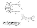
- Fig. 2 a schematic diagram of the main contact elements of a contact system 20 and of a mechanical element 23 according to the invention are shown.
- the contact system 20 is arranged with rotational symmetry around a longitudinal axis B inside a switching chamber of a high voltage interrupter unit.
- the switching chamber may be filled with vacuum or with an insulating gas, such as SF6, or a one-phase or two-phase dielectric medium, as described in WO 2010/142346 , e.g. fluoroketone, in particular C5-perfluoroketone and/or C6-perfluoroketone.
- One of the main contact elements is an inner contact element 21 which is shown in direct physical contact with an outer contact element, wherein the outer contact element is arranged in the form of a hollow cylinder 26 around the longitudinal axis B, with the cylinder body 26 ending in a multiple of contact fingers, two of which are shown here as contact finger 22 and contact finger 25.
- the contact fingers are aligned in parallel to one another and are distributed along the circumference of the cylinder body 26.
- a spring element in the form of a coil spring 23 is wound around the cylinder body 26 of the outer contact element.
- the contact pressure of the spring element applies a force F to the contact fingers 22, 25 which is directed towards the longitudinal axis B of the outer contact element.
- the coil spring 23 does not carry any current but performs a purely mechanical function, i.e. it is a mechanical element of contact system 20.
- the coil spring 23 is held in its position solely by its own spring force, i.e. it is not fixedly connected.
- the inventors have recognized that during the moving of the contact elements against each other and due to vibrations and small movements of the coil spring 23 w.r.t. the contact fingers, particles may be released between the contact fingers 22, 25 and the coil spring 23 due to abrasion. These particles may pollute the switching chamber, resulting in a high risk for decreasing the dielectric withstand in the high voltage interrupter unit.
- the coil spring in a layer of a synthetic, abrasion resistant material.
- the sheathing may be achieved by applying a surface coating.
- the inventors have further recognized that such a coating would considerably change the stiffness of the coil spring 23 thereby requiring further effort to redesign the overall arrangement of the spring.
- the layer of synthetic material as a flexible sleeve 24 around the coil spring 23, wherein the flexible sleeve 24 is made of a band of the synthetic material which is wound spirally around the coil spring 23.
- Figs. 3 and 4 show the coil spring 23 and how it peaks through equally distant gaps in a circular tube, the tube being made out of the spirally wound band of the synthetic material and forming the flexible sleeve 24.
- Some of the windings of the coil spring 23 can also be recognized as a shadowy silhouette shining through the transparent material of sleeve 24.
- Fig. 4 the flexible sleeve 24 with its equidistant gaps 41 is shown as a schematic diagram, wherein the sleeve 24 is not bent, thereby forming a straight tube.
- the stiffness of the spring i.e. the spring constant
- the stiffness of the spring remains virtually unaffected, as the sleeve 24 adapts to the shape of the coil spring 23 almost without any resistance. Due to that, an accurate assembly of the contact system is possible.
- PTFE polytetrafluoroethylene
- HF hydrofluoric acid
Landscapes
- Chemical & Material Sciences (AREA)
- Engineering & Computer Science (AREA)
- Composite Materials (AREA)
- Materials Engineering (AREA)
- Contacts (AREA)
- Gas-Insulated Switchgears (AREA)
Priority Applications (3)
| Application Number | Priority Date | Filing Date | Title |
|---|---|---|---|
| EP13179291.3A EP2835806A1 (fr) | 2013-08-05 | 2013-08-05 | Unité coupe-circuit haute tension présentant une meilleure endurance mécanique |
| US14/445,116 US20150034599A1 (en) | 2013-08-05 | 2014-07-29 | High voltage interrupter unit with improved mechanical endurance |
| CN201410457734.2A CN104347283B (zh) | 2013-08-05 | 2014-08-04 | 具有改进的机械耐久性的高压断续器单元 |
Applications Claiming Priority (1)
| Application Number | Priority Date | Filing Date | Title |
|---|---|---|---|
| EP13179291.3A EP2835806A1 (fr) | 2013-08-05 | 2013-08-05 | Unité coupe-circuit haute tension présentant une meilleure endurance mécanique |
Publications (1)
| Publication Number | Publication Date |
|---|---|
| EP2835806A1 true EP2835806A1 (fr) | 2015-02-11 |
Family
ID=48906186
Family Applications (1)
| Application Number | Title | Priority Date | Filing Date |
|---|---|---|---|
| EP13179291.3A Withdrawn EP2835806A1 (fr) | 2013-08-05 | 2013-08-05 | Unité coupe-circuit haute tension présentant une meilleure endurance mécanique |
Country Status (3)
| Country | Link |
|---|---|
| US (1) | US20150034599A1 (fr) |
| EP (1) | EP2835806A1 (fr) |
| CN (1) | CN104347283B (fr) |
Families Citing this family (20)
| Publication number | Priority date | Publication date | Assignee | Title |
|---|---|---|---|---|
| US10696906B2 (en) | 2017-09-29 | 2020-06-30 | Marathon Petroleum Company Lp | Tower bottoms coke catching device |
| US12000720B2 (en) | 2018-09-10 | 2024-06-04 | Marathon Petroleum Company Lp | Product inventory monitoring |
| US12031676B2 (en) | 2019-03-25 | 2024-07-09 | Marathon Petroleum Company Lp | Insulation securement system and associated methods |
| US11975316B2 (en) | 2019-05-09 | 2024-05-07 | Marathon Petroleum Company Lp | Methods and reforming systems for re-dispersing platinum on reforming catalyst |
| CA3212048A1 (fr) | 2019-05-30 | 2020-11-30 | Marathon Petroleum Company Lp | Procedes et systemes pour minimiser les emissions de so2 et de co dans les rechauffeurs de tirage naturel |
| US11384301B2 (en) | 2020-02-19 | 2022-07-12 | Marathon Petroleum Company Lp | Low sulfur fuel oil blends for stability enhancement and associated methods |
| US11905468B2 (en) | 2021-02-25 | 2024-02-20 | Marathon Petroleum Company Lp | Assemblies and methods for enhancing control of fluid catalytic cracking (FCC) processes using spectroscopic analyzers |
| US12461022B2 (en) | 2021-02-25 | 2025-11-04 | Marathon Petroleum Company Lp | Methods and assemblies for determining and using standardized spectral responses for calibration of spectroscopic analyzers |
| US11702600B2 (en) | 2021-02-25 | 2023-07-18 | Marathon Petroleum Company Lp | Assemblies and methods for enhancing fluid catalytic cracking (FCC) processes during the FCC process using spectroscopic analyzers |
| US11898109B2 (en) | 2021-02-25 | 2024-02-13 | Marathon Petroleum Company Lp | Assemblies and methods for enhancing control of hydrotreating and fluid catalytic cracking (FCC) processes using spectroscopic analyzers |
| US20250012744A1 (en) | 2021-02-25 | 2025-01-09 | Marathon Petroleum Company Lp | Methods and assemblies for enhancing control of refining processes using spectroscopic analyzers |
| US12473500B2 (en) | 2021-02-25 | 2025-11-18 | Marathon Petroleum Company Lp | Assemblies and methods for enhancing control of fluid catalytic cracking (FCC) processes using spectroscopic analyzers |
| US11467172B1 (en) | 2021-09-23 | 2022-10-11 | Marathon Petroleum Company Lp | Dispensing assembly to facilitate dispensing of fluid from a sample cylinder and related methods |
| US11692141B2 (en) | 2021-10-10 | 2023-07-04 | Marathon Petroleum Company Lp | Methods and systems for enhancing processing of hydrocarbons in a fluid catalytic cracking unit using a renewable additive |
| CA3188122A1 (fr) | 2022-01-31 | 2023-07-31 | Marathon Petroleum Company Lp | Systemes et methodes de reduction des points d'ecoulement de gras fondus |
| US12311305B2 (en) | 2022-12-08 | 2025-05-27 | Marathon Petroleum Company Lp | Removable flue gas strainer and associated methods |
| US12306076B2 (en) | 2023-05-12 | 2025-05-20 | Marathon Petroleum Company Lp | Systems, apparatuses, and methods for sample cylinder inspection, pressurization, and sample disposal |
| US12533615B2 (en) | 2023-06-02 | 2026-01-27 | Marathon Petroleum Company Lp | Methods and systems for reducing contaminants in a feed stream |
| US12415962B2 (en) | 2023-11-10 | 2025-09-16 | Marathon Petroleum Company Lp | Systems and methods for producing aviation fuel |
| US12599848B2 (en) | 2024-06-03 | 2026-04-14 | Marathon Petroleum Company Lp | Systems, analyzers, controllers, and associated methods to enhance fluid separation for distillation operations |
Citations (4)
| Publication number | Priority date | Publication date | Assignee | Title |
|---|---|---|---|---|
| US20070111590A1 (en) * | 2003-12-29 | 2007-05-17 | Areva T&D Sa | Electrical contact element for medium or high voltage electrical equipment, and corresponding, and corresponding method and equipment |
| WO2010129293A2 (fr) * | 2009-04-28 | 2010-11-11 | Bal Seal Engineering, Inc. | Ressorts hélicoïdaux inclinés multicouches et procédés associés |
| WO2010142346A1 (fr) | 2009-06-12 | 2010-12-16 | Abb Technology Ag | Milieu d'isolation diélectrique |
| EP2418666A1 (fr) * | 2010-08-13 | 2012-02-15 | ABB Technology AG | Agencement de contact électrique, spécialement pour un disjoncteur à moyenne tension aéro-isolé |
Family Cites Families (5)
| Publication number | Priority date | Publication date | Assignee | Title |
|---|---|---|---|---|
| US2193238A (en) * | 1936-12-14 | 1940-03-12 | Schweitzer & Conrad Inc | Switch |
| US7168117B2 (en) * | 2003-02-19 | 2007-01-30 | Dreamwell Ltd. | Multi-stranded coil spring |
| CN1951201A (zh) * | 2005-10-03 | 2007-04-25 | 貝特彻工业公司 | 用于电动旋转刀的柔性驱动轴套管 |
| CN201804723U (zh) * | 2009-12-16 | 2011-04-20 | 上海思源高压开关有限公司 | 触头联结机构 |
| CN202202683U (zh) * | 2011-08-03 | 2012-04-25 | 安徽爱德夏汽车零部件有限公司 | 一种用于汽车车门的铰链 |
-
2013
- 2013-08-05 EP EP13179291.3A patent/EP2835806A1/fr not_active Withdrawn
-
2014
- 2014-07-29 US US14/445,116 patent/US20150034599A1/en not_active Abandoned
- 2014-08-04 CN CN201410457734.2A patent/CN104347283B/zh active Active
Patent Citations (4)
| Publication number | Priority date | Publication date | Assignee | Title |
|---|---|---|---|---|
| US20070111590A1 (en) * | 2003-12-29 | 2007-05-17 | Areva T&D Sa | Electrical contact element for medium or high voltage electrical equipment, and corresponding, and corresponding method and equipment |
| WO2010129293A2 (fr) * | 2009-04-28 | 2010-11-11 | Bal Seal Engineering, Inc. | Ressorts hélicoïdaux inclinés multicouches et procédés associés |
| WO2010142346A1 (fr) | 2009-06-12 | 2010-12-16 | Abb Technology Ag | Milieu d'isolation diélectrique |
| EP2418666A1 (fr) * | 2010-08-13 | 2012-02-15 | ABB Technology AG | Agencement de contact électrique, spécialement pour un disjoncteur à moyenne tension aéro-isolé |
Also Published As
| Publication number | Publication date |
|---|---|
| CN104347283B (zh) | 2019-10-15 |
| US20150034599A1 (en) | 2015-02-05 |
| CN104347283A (zh) | 2015-02-11 |
Similar Documents
| Publication | Publication Date | Title |
|---|---|---|
| EP2835806A1 (fr) | Unité coupe-circuit haute tension présentant une meilleure endurance mécanique | |
| CN101772865B (zh) | 真空故障断路器 | |
| US9263199B2 (en) | Electrical contact arrangement and air insulated medium voltage circuit breaker including the electrical contact arrangement | |
| KR101733899B1 (ko) | 서지 피뢰기 | |
| JP5989385B2 (ja) | 接点要素の二つのセットを有するスイッチ | |
| US20070246444A1 (en) | Contact system for an electrical switching device | |
| EP2549503A1 (fr) | Interrupteur sous vide avec commande simple et intervalle double intégré | |
| JP7118992B2 (ja) | 真空スイッチ | |
| CN109920691B (zh) | 用于电气开关装置的真空瓶 | |
| KR20140012164A (ko) | 과전압 차단기 | |
| CN101359548B (zh) | 真空绝缘开关及真空绝缘开关装置 | |
| EP3155627B1 (fr) | Ensemble commutateur et résistance commandé par interrupteur | |
| JP5629589B2 (ja) | 開閉器 | |
| RU2634749C2 (ru) | Катушка аксиального магнитного поля для вакуумного прерывателя | |
| EP2362407B1 (fr) | Düse für einen Leistungsschalter und Leistungsschalter mit einer solchen Düse | |
| CN105185648A (zh) | 一种真空开关管 | |
| US11462375B2 (en) | Make contact system | |
| CN114631161A (zh) | 用于具有主和副电流路径的电路的真空开关装置 | |
| CA2833486C (fr) | Appareil de commutation electrique a tension moyenne ou elevee | |
| RU2462005C1 (ru) | Устройство металлизации подвижных элементов конструкции | |
| KR101558137B1 (ko) | 회로 차단기 | |
| WO2016001328A1 (fr) | Disjoncteur | |
| KR20150070296A (ko) | 개폐 장치 | |
| CN203103204U (zh) | 高压隔离开关触头 | |
| EP3172754A1 (fr) | Disjoncteur pour lignes et systèmes électriques avec courant fort et valeur de court-circuit élevée |
Legal Events
| Date | Code | Title | Description |
|---|---|---|---|
| PUAI | Public reference made under article 153(3) epc to a published international application that has entered the european phase |
Free format text: ORIGINAL CODE: 0009012 |
|
| 17P | Request for examination filed |
Effective date: 20130805 |
|
| AK | Designated contracting states |
Kind code of ref document: A1 Designated state(s): AL AT BE BG CH CY CZ DE DK EE ES FI FR GB GR HR HU IE IS IT LI LT LU LV MC MK MT NL NO PL PT RO RS SE SI SK SM TR |
|
| AX | Request for extension of the european patent |
Extension state: BA ME |
|
| R17P | Request for examination filed (corrected) |
Effective date: 20150803 |
|
| GRAP | Despatch of communication of intention to grant a patent |
Free format text: ORIGINAL CODE: EPIDOSNIGR1 |
|
| GRAJ | Information related to disapproval of communication of intention to grant by the applicant or resumption of examination proceedings by the epo deleted |
Free format text: ORIGINAL CODE: EPIDOSDIGR1 |
|
| RIC1 | Information provided on ipc code assigned before grant |
Ipc: H01H 1/38 20060101AFI20160713BHEP Ipc: H01H 1/50 20060101ALI20160713BHEP |
|
| GRAP | Despatch of communication of intention to grant a patent |
Free format text: ORIGINAL CODE: EPIDOSNIGR1 |
|
| INTG | Intention to grant announced |
Effective date: 20160801 |
|
| GRAJ | Information related to disapproval of communication of intention to grant by the applicant or resumption of examination proceedings by the epo deleted |
Free format text: ORIGINAL CODE: EPIDOSDIGR1 |
|
| INTC | Intention to grant announced (deleted) | ||
| RAP1 | Party data changed (applicant data changed or rights of an application transferred) |
Owner name: ABB SCHWEIZ AG |
|
| GRAP | Despatch of communication of intention to grant a patent |
Free format text: ORIGINAL CODE: EPIDOSNIGR1 |
|
| INTG | Intention to grant announced |
Effective date: 20160830 |
|
| INTC | Intention to grant announced (deleted) | ||
| INTG | Intention to grant announced |
Effective date: 20160928 |
|
| STAA | Information on the status of an ep patent application or granted ep patent |
Free format text: STATUS: GRANT OF PATENT IS INTENDED |
|
| STAA | Information on the status of an ep patent application or granted ep patent |
Free format text: STATUS: THE APPLICATION IS DEEMED TO BE WITHDRAWN |
|
| 18D | Application deemed to be withdrawn |
Effective date: 20170209 |