EP2836630B1 - Rouleau de déchirage - Google Patents
Rouleau de déchirage Download PDFInfo
- Publication number
- EP2836630B1 EP2836630B1 EP13722058.8A EP13722058A EP2836630B1 EP 2836630 B1 EP2836630 B1 EP 2836630B1 EP 13722058 A EP13722058 A EP 13722058A EP 2836630 B1 EP2836630 B1 EP 2836630B1
- Authority
- EP
- European Patent Office
- Prior art keywords
- shaft
- toothed
- extraction roller
- toothed discs
- teeth
- Prior art date
- Legal status (The legal status is an assumption and is not a legal conclusion. Google has not performed a legal analysis and makes no representation as to the accuracy of the status listed.)
- Active
Links
Images
Classifications
-
- D—TEXTILES; PAPER
- D01—NATURAL OR MAN-MADE THREADS OR FIBRES; SPINNING
- D01G—PRELIMINARY TREATMENT OF FIBRES, e.g. FOR SPINNING
- D01G7/00—Breaking or opening fibre bales
- D01G7/04—Breaking or opening fibre bales by means of toothed members
Definitions
- the invention relates to a removal roller for the mechanical opening of fiber bales.
- the removal roller comprises a shaft rotatable about a shaft axis and toothed disks fastened to this shaft.
- the toothed discs are provided with teeth on their outer circumference.
- Discharge rollers are used in so-called bale removal machines or bale openers to release fibers or fiber flakes from pressed fiber bales.
- bale removal machines For this purpose, one or more removal rollers are moved across the fiber bales.
- Bale openers are also known from the prior art in which the fiber bales are moved past a stationary removal roller. In this case, the teeth of the removal roller engage in the fiber bales and tear or tease due to the rotation of the removal roller fibers respectively fiber flakes out of the fiber bale out.
- the bale stripping machine is at the beginning of processing lines in a spinning mill preparation (processing plant) for the processing of fiber material, such as cotton or synthetic fibers or their mixtures, and has a decisive influence on the continuity of the processes within the spinning mill preparation.
- the fiber material delivered in bales is removed from the bales by removing fiber flakes and transferred to a pneumatic transport system.
- the pneumatic transport system brings the fiber flakes through pipes to the following cleaning machines.
- a grate is provided between the removal roller and the fiber bale.
- the teeth of the removal roller reach through the grate.
- the rust serves as a retaining element for the fiber bales. Due to the grate elements, which rest on the surface of the fiber bales, it is prevented that too large or irregular fiber flakes are torn out of the fiber bale by the teeth of the removal roller.
- removal rollers are known from the prior art.
- the EP 0 058 781 a removal roller in which the toothed disks are attached to semicircular shells.
- Two of these half shells each comprise the shaft of the removal roller and are fastened to each other such that an interference fit results between the half shells and the shaft.
- a disadvantage of the disclosed construction of the discharge roller is the complex construction of the half-shells and the removable by a press fit attachment of the toothed discs, which can be solved even during operation.
- FIG. 669 214 Another embodiment of a removal roller discloses the CH 669 214 ,
- the toothed disks are helical.
- the toothed disks are punched circular from a sheet metal and provided with an opening cut, to be subsequently bent to a helix.
- the CH 669 214 also a helical arrangement of individual teeth.
- the helix as well as the individual teeth are fixed by welding on a cylindrical base body.
- the helix are arranged left or right-handed rotation on the base body.
- the helical arrangement of the teeth should be made possible to achieve a uniform removal of fiber flakes over a certain width.
- the pitch of the helix corresponds to the distance between two grate elements through which the teeth of the removal roller pass.
- a disadvantage of the disclosed construction is that, after completion of a handling of the removal roller of the subsequent tooth of a next handling causes a return of Abtragungsortes over the entire width between two grate elements. As a result, the surfaces of the fiber bales are processed between two grate elements only in one direction.
- a removal roller discloses the FR 1 286 494 A namely, a removal roller for mechanically opening fiber bales with a shaft rotatable about a shaft axis and circular toothed disks fixed to this shaft, which are provided with teeth on their outer circumference, wherein the toothed disks have an inclination with an inclination angle alpha against the shaft axis.
- the object of the invention is to provide a removal roller which is simple in terms of its design, which allows a removal which moves continuously over the surface of the fiber bales.
- a novel removal roller is proposed with a shaft rotatable about a shaft axis and attached to this shaft circular toothed discs, which are provided at its outer periphery with teeth.
- the Toothed disks have an elliptically shaped, central recess with which they enclose the shaft in an annular manner.
- the toothed disks have an inclination against the shaft axis.
- the toothed discs have a central elliptical recess.
- the shape of the elliptical recess used is symmetrical.
- the ellipse has a largest length, which lies on a first axis.
- the shortest length of the ellipse is in a symmetrical shape on a second axis perpendicular to the first axis.
- the shaft diameter corresponds to the smallest length of the elliptical recess in the toothed discs, with a slight clearance is provided between the recess and the shaft surface.
- the smallest length of the elliptical recess is thus slightly larger than the diameter of the shaft to allow easy installation of the toothed pulleys on the shaft.
- the largest length of the elliptical recess corresponds to the circumference of the shaft measured at a bevel cut at the same angle which is provided for the inclination of the toothed discs.
- the largest length of the elliptical recess of the toothed disc is therefore to be chosen such that there is a certain angle of inclination of the toothed disc on the shaft against the shaft axis.
- the shaft provided for fastening the toothed pulleys may be a solid shaft or else a hollow shaft. It is also conceivable to use a wave-like circular skeleton, which is surrounded annularly by the toothed discs with their recess.
- the toothed disks are rotated in their sequence in the direction of the shaft axis by a certain angle against each other in the radial direction.
- the individual successively arranged on the shaft toothed pulleys are identical in their construction.
- the toothed disks are different in their radial arrangement. This ensures that not all toothed discs with a tooth engage simultaneously in the fiber bales. Due to the radial rotation is achieved that a tooth of the first toothed disc engages in the fiber bale and only after the shaft has been further rotated, a tooth of the subsequent toothed disc comes into engagement. This also ensures that, viewed over the entire length of the removal roller, a continuous removal of fibers from the fiber bales takes place. Also, the staggered engagement of the individual toothed pulleys reduces transmission of vibrations.
- the toothed disks in the elliptical recess at the location of a largest diameter on a projection are dimensioned such that the clear width of the recess at the location of the projections or the one projection is not smaller than the smallest length of the recess. This ensures that the toothed discs can be pushed despite the projections on the shaft.
- the shaft has recesses on its surface, which receive the projections accordingly. The dimensions of the recesses in the shaft surface are matched in their dimensions to the projections of the toothed discs.
- the toothed discs can be pushed onto the shaft and locked in their predetermined position by means of the projections in the recesses in the shaft surface.
- the recesses in the shaft surface are helically arranged in the direction of the shaft axis in accordance with a certain radial rotation of the successive toothed disks.
- the projection of the toothed disc forms a positive connection in cooperation with the recess in the shaft surface.
- a force transmission from the toothed disk to the shaft can take place through the projections and the depressions.
- the toothed discs are secured by welding or gluing in position on the shaft.
- the envisaged securing the toothed pulleys on the shaft by suitable means is only the persistence of the toothed discs in their position. Accordingly, a simple backup can be made, for example, by simple welding points or even selectively applied adhesives.
- a Power transmission need not be ensured by a suitable fastener such as screws or welds, since there is a positive connection between the shaft and toothed pulley.
- the shaft is formed as a tube and the recesses are applied as through holes.
- the projections arranged in the toothed disks are correspondingly received by the holes in the jacket of the shaft designed as a pipe.
- the toothed disks have an inclination against the shaft axis at an angle of 5 ° to 20 °.
- the angle of inclination is measured against a plane perpendicular to the longitudinal direction of the shaft axis.
- the inclination angle can be measured in one direction or the other.
- the size of the angle of inclination is determined by the greatest length of the elliptical recess of the toothed discs.
- the toothed disks of a removal roller are manufactured with the same inclination, ie with the same inclination angle. However, it is conceivable to vary the inclination between the individual toothed disks or areas of the removal roller.
- the inclination of the toothed disks determines the removal width of a single toothed disc. This affects the design of the grate respectively the distance between the individual grate elements, between which engage the teeth of the toothed discs. If the toothed disks of a removal roller are fastened to the shaft at different angles of inclination, the rust used must be adapted accordingly. Particularly preferably, all toothed disks of a removal roller with an identical inclination angle of 9 ° are arranged on the shaft.
- the radial rotation between two successive toothed disks is provided at an angle of 6 ° to 36 °. This results after a certain number of toothed pulleys full handling.
- the tenth toothed disk is arranged identically to the first toothed disk.
- the angle of rotation is selected depending on the number of toothed pulleys on the entire removal roller, resulting in a whole number of helical lines.
- Particularly preferred are the individual toothed discs with an angle twisted against each other, which corresponds to the nth part of 360 ° or a multiple thereof, where n stands for the number of toothed pulleys on the removal roller.
- the resulting due to the inclination of the toothed discs dynamic imbalance is compensated.
- an oppositely inclined toothed disc is present for compensation.
- the toothed disks can also be arranged in mirror image on the shaft, wherein the direction of rotation changes after one revolution.
- the toothed discs at the outer ends of the discharge roller may have a different rotation than the toothed discs which are arranged in the middle of the shaft.
- the toothed discs each comprise between four and twelve teeth.
- the teeth are arranged on the outer circumference of the toothed discs.
- the outer circumference of the toothed discs is circular, in contrast to the recess.
- a rotationally symmetrical arrangement of the teeth is possible.
- a toothed wheel has six teeth.
- the teeth are subjected to a heat treatment on their outer surface to give them a certain wear resistance. As a heat treatment, a compensation or curing are used. However, other methods for increasing the wear resistance are conceivable, such as a coating instead of the heat treatment. A sufficient wear resistance can be achieved under certain circumstances by the appropriate selection of the material to be used.
- the teeth preferably have an outer shape, which allows operation of the removal roller in both directions. As a result, the removal roller can be moved over the fiber bales in both directions and these can also be removed in both directions.
- the toothed disks in the elliptical recess at at least one point have a recess and the shaft on its surface elevations, wherein the recess of the toothed disc in interaction with the survey in the shaft surface forms a positive connection.
- the tooth tips of the teeth lie on an elliptical envelope of the toothed disks, wherein the toothed disks are mounted on the shaft at the angle of inclination ⁇ such that the tooth tips of the teeth come to lie on a circular enveloping circle of the removal roller with an enveloping circle diameter D. , This ensures that all tooth tips engage equally deep in the bales to be removed.
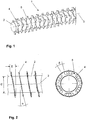
- FIG. 1 shows a schematic perspective view of a part of a removal roller 1.
- the removal roller 1 comprises a shaft 2 with a shaft axis 3 and arranged on the shaft 2 toothed disks 4.
- the shaft 2 is shown as a solid shaft, but may also be suitable as a hollow shaft or other suitable Form of a circular body can be used.
- the toothed discs 4 are provided at its outer periphery with six teeth 5.
- the toothed disks 4 are arranged at a uniform distance on the shaft 2. Opposite the shaft axis 3, the toothed discs 4 are mounted inclined. In addition, a subsequent toothed disc 4 is arranged rotated relative to a preceding toothed disc 4.
- FIG. 2 schematically shows in the left representation of a side view and in the right representation of a top view of a removal roller 1.
- the left illustration shows a section of a removal roller 1 with four mounted on a shaft 2 toothed disks 4.
- the shaft has an outer diameter C.
- the toothed disks 4 are with a tilt angle ⁇ fixed on the shaft 2.
- the inclination angle ⁇ is the same for all four toothed disks 4 shown.
- the toothed disks 4 are arranged in their sequence with a radial rotation at the angle ⁇ . Since the toothed disc 4 are constructed identically, the displacement ⁇ also results in an offset of the teeth 5 of the successive toothed discs 4 by the angle ⁇ .
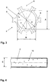
- Fig. 3 shows a schematic representation of a toothed disc 4 of a removal roller.
- the toothed disc 4 is annular.
- On the outer surface AF six teeth 5 are arranged.
- the teeth 5 are mounted on the circumference of the toothed disc 4 at regular intervals.
- the teeth 5 have a shape which allows operation of the removal roller in both directions of rotation.
- the teeth 5 are symmetrically shaped such that the same effect is produced when the toothed disc 4 rotates in both directions of rotation.
- a recess 6 is provided in the center of the toothed disc 4.
- the recess 6 is elliptical in shape and has a minimum length B in a first axis 9 and a maximum length A in a second axis 8 of the ellipse.
- the first axis 9 and the second axis 8 are perpendicular to each other, resulting in an axisymmetric elliptical shape of the recess 6.
- the elliptical recess 6 is applied centrally to an elliptical envelope 11 of the toothed disc 4, on which the tooth tips 5a of the teeth 5 of the toothed disc 4 are located.
- the elliptical envelope 11 of the respective toothed disc 4, on which the tooth tips 5a lie, is chosen so that in the attached state of the toothed disc 4 on the shaft 2 at an inclination angle ⁇ the tooth tips 5a in a circular enveloping circle H with a Hüllnikischen messyr D of the removal roller 1 run. This ensures that all tooth tips 5a engage equally deep into the bale and remove all teeth 5 the same amount of material.
- a projection 7 is provided in the second axis 8 of the largest length A of the recess 6, a projection 7 is provided.
- the projection 7 is dimensioned such that the largest length A minus the height of the cam 7 of the recess 6 is not smaller than the smallest length B of the recess 6. This is true even if on each side of the recess 6 in the second axis 8, a projection 7 is provided.
- Fig. 4 shows a schematic representation of a shaft 2 of a removal roller with a diameter C.
- the diameter C of the shaft 2 is slightly smaller than the smallest length B of the recess 6 of a toothed disc 4 (see FIG. 3 ).
- recesses 10 are provided in the surface of the shaft 2 .
- the recesses 10 are in their dimensions on the projections 7 (see FIG. 3 ), so that upon engagement of the projections 7 in the recesses 10 forms a positive connection between the shaft 4 and toothed disc.
- the depressions are arranged helically in the sequence of the shaft 2 in their sequence.
Landscapes
- Engineering & Computer Science (AREA)
- Textile Engineering (AREA)
- Preliminary Treatment Of Fibers (AREA)
Claims (16)
- Rouleau d'enlèvement (1), destiné à ouvrir mécaniquement des balles de fibres, comprenant un arbre (2) rotatif sur un axe d'arbre (3) et des disques dentées (4) de forme circulaire qui sont fixés à cet arbre (2) et qui sont pourvus de dents (5) à leur périphérie extérieure, caractérisé en ce que les disques dentés (4) comportent un évidement central (6) de forme elliptique au moyen duquel ils entourent l'arbre (2) annulairement et présentent une inclinaison d'un angle d'inclinaison (α) par rapport à l'axe d'arbre (3).
- Rouleau d'enlèvement (1) selon la revendication 1, caractérisé en ce que les disques dentés (4) tournés dans une direction radiale les uns par rapport aux autres d'un certain angle (β) dans leur ordre en direction de l'axe d'arbre (3).
- Rouleau d'enlèvement (1) selon la revendication 1 ou 2, caractérisé en ce que les disques dentés (4) comportent une saillie (7) à un emplacement d'une plus grande longueur (A) dans l'évidement elliptique (6).
- Rouleau d'enlèvement (1) selon la revendication 1 ou 2, caractérisé en ce que les disques dentés (4) comportent deux saillies opposées (7) à l'emplacement de la plus grande longueur (A) dans l'évidement elliptique (6).
- Rouleau d'enlèvement (1) selon l'une des revendications 3 ou 4, caractérisé en ce que l'arbre (2) comporte au niveau de sa surface des dépressions (10) qui sont disposées en hélice dans la direction de l'axe d'arbre (3) et qui reçoivent les saillies (7) en correspondance.
- Rouleau d'enlèvement (1) selon la revendication 5, caractérisé en ce que la saillie (7) du disque denté (4) forme en coopération avec l'évidement (10) une liaison par complémentarité de formes dans la surface de l'arbre.
- Rouleau d'enlèvement (1) selon l'une des revendications précédentes, caractérisé en ce que les disques dentés (4) présentent une inclinaison de l'angle d'inclinaison (α) de 5° à 20° par rapport à l'axe d"arbre (3).
- Rouleau d'enlèvement (1) selon l'une des revendications 2 ou 3 à 7, au moins en référence la revendication 2, caractérisé en ce que la torsion radiale entre deux disques dentés (4) successifs sont prévus pour être d'un angle (β) de 6° à 36°.
- Rouleau d'enlèvement (1) selon l'une des revendications 2 ou 3 à 8, au moins en référence à la revendication 2, caractérisé en ce que l'angle (β) de la torsion radiale entre deux disques dentés (4) successifs correspond à la nième partie de 360° ou à un multiple de celle-ci, n représentant le nombre de disques dentés sur le rouleau d'enlèvement.
- Rouleau d'enlèvement (1) selon l'une des revendications précédentes, caractérisé en ce que les disques dentés (4) sont fixés par soudage ou collage dans leur position sur l'arbre (2).
- Rouleau d'enlèvement (1) selon l'une des revendications précédentes, caractérisé en ce que le disque denté (4) comporte entre quatre et douze dents (5) qui sont réparties uniformément sur la périphérie du disque denté (4).
- Rouleau d'enlèvement (1) selon l'une des revendications 5, 6 ou 7 à 11, au moins en référence à la revendication 5, caractérisé en ce que l'arbre (2) est un tube et les évidements (10) sont réalisés sous la forme de trous traversants.
- Rouleau d'enlèvement (1) selon l'une des revendications précédentes, caractérisé en ce que les dents (5) sont soumises à un traitement thermique au niveau de leur surface extérieure.
- Rouleau d'enlèvement (1) selon l'une des revendications précédentes, caractérisé en ce que les dents (5) ont une forme extérieure qui permet une opération d'ouverture des balles de fibres avec le rouleau d'enlèvement (1) dans les deux sens de rotation.
- Rouleau d'enlèvement (1) selon la revendication 1 ou 2, caractérisé en ce que les disques dentés (4) comportent un évidement à au moins un retrait dans l'évidement elliptique (6) et l'arbre (2) comportent des élévations au niveau de sa surface (10), le retrait du disque denté (4) formant, en coopération avec l'élévation de la surface de l'arbre, une liaison par complémentarité de formes.
- Rouleau d'enlèvement (1) selon l'une des revendications précédentes, caractérisé en ce que les pointes (5a) des dents (5) se trouvent sur une enveloppante elliptique (11) des disques dentés (4), les disques dentés (4) étant fixés sur l'arbre (2) avec l'angle d'inclinaison (α) de telle manière que les pointes (5a) des dents (5) se trouvent sur un cercle enveloppant circulaire (H) du rouleau d'enlèvement (1) avec un diamètre de cercle enveloppant (D).
Applications Claiming Priority (2)
| Application Number | Priority Date | Filing Date | Title |
|---|---|---|---|
| CH00508/12A CH706351A1 (de) | 2012-04-13 | 2012-04-13 | Abtragwalze. |
| PCT/IB2013/000740 WO2013153444A1 (fr) | 2012-04-13 | 2013-04-05 | Rouleau de déchirage |
Publications (2)
| Publication Number | Publication Date |
|---|---|
| EP2836630A1 EP2836630A1 (fr) | 2015-02-18 |
| EP2836630B1 true EP2836630B1 (fr) | 2018-07-25 |
Family
ID=48428521
Family Applications (1)
| Application Number | Title | Priority Date | Filing Date |
|---|---|---|---|
| EP13722058.8A Active EP2836630B1 (fr) | 2012-04-13 | 2013-04-05 | Rouleau de déchirage |
Country Status (5)
| Country | Link |
|---|---|
| EP (1) | EP2836630B1 (fr) |
| CN (1) | CN104246034B (fr) |
| CH (1) | CH706351A1 (fr) |
| TR (1) | TR201815006T4 (fr) |
| WO (1) | WO2013153444A1 (fr) |
Cited By (1)
| Publication number | Priority date | Publication date | Assignee | Title |
|---|---|---|---|---|
| EP3663443A1 (fr) * | 2018-12-03 | 2020-06-10 | Maschinenfabrik Rieter AG | Rouleau d'extraction |
Families Citing this family (4)
| Publication number | Priority date | Publication date | Assignee | Title |
|---|---|---|---|---|
| CN111254524A (zh) | 2018-12-03 | 2020-06-09 | 里特机械公司 | 抓棉辊 |
| CN113604909A (zh) * | 2021-08-11 | 2021-11-05 | 安徽宜民服饰股份有限公司 | 一种生物基纤维可降解面料制备方法 |
| CN113977174B (zh) * | 2021-11-17 | 2025-03-11 | 南通棉花机械有限公司 | 一种刺钉辊的焊接工装 |
| CN114875526B (zh) * | 2022-06-22 | 2024-08-23 | 安徽富春纺织有限公司 | 纺纱加工用清花抓棉遇异物自动停车报警装置 |
Family Cites Families (13)
| Publication number | Priority date | Publication date | Assignee | Title |
|---|---|---|---|---|
| US1413020A (en) * | 1920-02-03 | 1922-04-18 | Garner Gin Company Inc | Toothed drum for treating cotton |
| US1790339A (en) * | 1930-01-02 | 1931-01-27 | Picker roll | |
| FR1286494A (fr) * | 1960-04-29 | 1962-03-02 | Rieter Ag Maschf | Raboteuse de balles |
| JPS5293722U (fr) * | 1975-12-27 | 1977-07-13 | ||
| ATE13699T1 (de) | 1981-02-20 | 1985-06-15 | Rieter Ag Maschf | Abtragwalze fuer faserballen. |
| EP0069847B1 (fr) * | 1981-07-15 | 1985-09-11 | Maschinenfabrik Rieter Ag | Procédé et dispositif pour ouvrir des balles de fibres textiles |
| DE8327082U1 (de) * | 1983-09-21 | 1985-03-07 | Hergeth Hollingsworth GmbH, 4408 Dülmen | Öffnungsvorrichtung zum Öffnen von gepreßten Faserballen |
| DE3438133A1 (de) * | 1984-10-18 | 1986-04-30 | Staedtler & Uhl, 8540 Schwabach | Aufloesewalze fuer open-end spinnmaschinen |
| DE3504615C1 (de) * | 1985-02-11 | 1986-06-19 | Trützschler GmbH & Co KG, 4050 Mönchengladbach | OEffnerwalze zum OEffnen von Faserballen,wie Baumwollballen,Chemiefaserballen o.dgl. |
| DE8503753U1 (de) * | 1985-02-11 | 1990-09-06 | Trützschler GmbH & Co KG, 4050 Mönchengladbach | Öffnerwalze zum Öffnen von Faserballen, wie Baumwollballen, Chemiefaserballen o.dgl. |
| DE3706268C3 (de) * | 1987-02-26 | 1995-02-09 | Rieter Ingolstadt Spinnerei | Vorrichtung zum Abarbeiten von Faserballen |
| US7178749B2 (en) * | 2005-01-11 | 2007-02-20 | Moyno, Inc. | Pump with cutting assembly |
| CN101705530B (zh) * | 2009-11-05 | 2011-12-07 | 太仓市万龙非织造工程有限公司 | 一种开包机及该开包机上的爬钉帘 |
-
2012
- 2012-04-13 CH CH00508/12A patent/CH706351A1/de not_active Application Discontinuation
-
2013
- 2013-04-05 CN CN201380019439.2A patent/CN104246034B/zh active Active
- 2013-04-05 EP EP13722058.8A patent/EP2836630B1/fr active Active
- 2013-04-05 TR TR2018/15006T patent/TR201815006T4/tr unknown
- 2013-04-05 WO PCT/IB2013/000740 patent/WO2013153444A1/fr not_active Ceased
Non-Patent Citations (1)
| Title |
|---|
| None * |
Cited By (1)
| Publication number | Priority date | Publication date | Assignee | Title |
|---|---|---|---|---|
| EP3663443A1 (fr) * | 2018-12-03 | 2020-06-10 | Maschinenfabrik Rieter AG | Rouleau d'extraction |
Also Published As
| Publication number | Publication date |
|---|---|
| CN104246034B (zh) | 2017-03-22 |
| EP2836630A1 (fr) | 2015-02-18 |
| WO2013153444A1 (fr) | 2013-10-17 |
| CH706351A1 (de) | 2013-10-15 |
| TR201815006T4 (tr) | 2018-11-21 |
| CN104246034A (zh) | 2014-12-24 |
Similar Documents
| Publication | Publication Date | Title |
|---|---|---|
| DE2124700C3 (de) | Lineareinstellvorrichtung | |
| EP0575858B1 (fr) | Centrifugeuse | |
| EP4238451B1 (fr) | Ensemble brosse | |
| WO2013153444A1 (fr) | Rouleau de déchirage | |
| DE3504615C1 (de) | OEffnerwalze zum OEffnen von Faserballen,wie Baumwollballen,Chemiefaserballen o.dgl. | |
| EP2188064B1 (fr) | Élément de crible excentrique pour cribles à disques | |
| EP1277002B1 (fr) | Poulie dentee a bordure | |
| EP1935560A1 (fr) | Meule réfrigérante, système de rectification et outil de rectification | |
| EP0840021A1 (fr) | Dispositif pour la connexion d'éléments de montage | |
| DE2519023B2 (de) | Axiale Lagerbefestigung eines Wälzlagers | |
| EP2150716B1 (fr) | Embrayage | |
| EP3225325B1 (fr) | Outil de bobinage pour machines à enroulement de ressort | |
| EP0205738A2 (fr) | Dispositif pour transporter et retourner en continu des pièces à travers une enceinte de traitement | |
| WO2007012535A1 (fr) | Dispositif ventilateur pour un appareil de cuisson | |
| WO2019120640A1 (fr) | Dispositif de séparation | |
| DE112014004828B4 (de) | Gratbeständige Befestigungsmittel-montierte Lageranordnung | |
| DE102009001406A1 (de) | Vorrichtung zum Befestigen eines konzentrischen Teils auf einem Zapfen eines Zylinders einer Druckmaschine | |
| EP1046439B1 (fr) | Rouleau pour tête radiale à rouler des filets | |
| DE4319031C2 (de) | Wickelvorrichtung | |
| CH715608A1 (de) | Abtragwalze. | |
| WO2018133979A1 (fr) | Outil destiné à l'usinage de surfaces, de zones d'arête et de contours | |
| DE102006060761A1 (de) | Planeten-Wälz-Gewindespindel mit ringförmigem Halteelement | |
| CH712404A1 (de) | Reinigungsvorrichtung für die Oberflächenreinigung eines Stangenmaterials. | |
| DE102017106383A1 (de) | Nabenantriebsvorrichtung | |
| DE2648550B2 (de) | Antriebsvorrichtung |
Legal Events
| Date | Code | Title | Description |
|---|---|---|---|
| PUAI | Public reference made under article 153(3) epc to a published international application that has entered the european phase |
Free format text: ORIGINAL CODE: 0009012 |
|
| 17P | Request for examination filed |
Effective date: 20141017 |
|
| AK | Designated contracting states |
Kind code of ref document: A1 Designated state(s): AL AT BE BG CH CY CZ DE DK EE ES FI FR GB GR HR HU IE IS IT LI LT LU LV MC MK MT NL NO PL PT RO RS SE SI SK SM TR |
|
| AX | Request for extension of the european patent |
Extension state: BA ME |
|
| DAX | Request for extension of the european patent (deleted) | ||
| 17Q | First examination report despatched |
Effective date: 20161010 |
|
| GRAP | Despatch of communication of intention to grant a patent |
Free format text: ORIGINAL CODE: EPIDOSNIGR1 |
|
| STAA | Information on the status of an ep patent application or granted ep patent |
Free format text: STATUS: GRANT OF PATENT IS INTENDED |
|
| INTG | Intention to grant announced |
Effective date: 20180416 |
|
| GRAS | Grant fee paid |
Free format text: ORIGINAL CODE: EPIDOSNIGR3 |
|
| GRAA | (expected) grant |
Free format text: ORIGINAL CODE: 0009210 |
|
| STAA | Information on the status of an ep patent application or granted ep patent |
Free format text: STATUS: THE PATENT HAS BEEN GRANTED |
|
| AK | Designated contracting states |
Kind code of ref document: B1 Designated state(s): AL AT BE BG CH CY CZ DE DK EE ES FI FR GB GR HR HU IE IS IT LI LT LU LV MC MK MT NL NO PL PT RO RS SE SI SK SM TR |
|
| REG | Reference to a national code |
Ref country code: GB Ref legal event code: FG4D Free format text: NOT ENGLISH |
|
| REG | Reference to a national code |
Ref country code: CH Ref legal event code: EP |
|
| REG | Reference to a national code |
Ref country code: AT Ref legal event code: REF Ref document number: 1021870 Country of ref document: AT Kind code of ref document: T Effective date: 20180815 |
|
| REG | Reference to a national code |
Ref country code: IE Ref legal event code: FG4D Free format text: LANGUAGE OF EP DOCUMENT: GERMAN |
|
| REG | Reference to a national code |
Ref country code: DE Ref legal event code: R096 Ref document number: 502013010684 Country of ref document: DE |
|
| REG | Reference to a national code |
Ref country code: NL Ref legal event code: MP Effective date: 20180725 |
|
| REG | Reference to a national code |
Ref country code: LT Ref legal event code: MG4D |
|
| PG25 | Lapsed in a contracting state [announced via postgrant information from national office to epo] |
Ref country code: NL Free format text: LAPSE BECAUSE OF FAILURE TO SUBMIT A TRANSLATION OF THE DESCRIPTION OR TO PAY THE FEE WITHIN THE PRESCRIBED TIME-LIMIT Effective date: 20180725 |
|
| PG25 | Lapsed in a contracting state [announced via postgrant information from national office to epo] |
Ref country code: FI Free format text: LAPSE BECAUSE OF FAILURE TO SUBMIT A TRANSLATION OF THE DESCRIPTION OR TO PAY THE FEE WITHIN THE PRESCRIBED TIME-LIMIT Effective date: 20180725 Ref country code: LT Free format text: LAPSE BECAUSE OF FAILURE TO SUBMIT A TRANSLATION OF THE DESCRIPTION OR TO PAY THE FEE WITHIN THE PRESCRIBED TIME-LIMIT Effective date: 20180725 Ref country code: PL Free format text: LAPSE BECAUSE OF FAILURE TO SUBMIT A TRANSLATION OF THE DESCRIPTION OR TO PAY THE FEE WITHIN THE PRESCRIBED TIME-LIMIT Effective date: 20180725 Ref country code: BG Free format text: LAPSE BECAUSE OF FAILURE TO SUBMIT A TRANSLATION OF THE DESCRIPTION OR TO PAY THE FEE WITHIN THE PRESCRIBED TIME-LIMIT Effective date: 20181025 Ref country code: SE Free format text: LAPSE BECAUSE OF FAILURE TO SUBMIT A TRANSLATION OF THE DESCRIPTION OR TO PAY THE FEE WITHIN THE PRESCRIBED TIME-LIMIT Effective date: 20180725 Ref country code: RS Free format text: LAPSE BECAUSE OF FAILURE TO SUBMIT A TRANSLATION OF THE DESCRIPTION OR TO PAY THE FEE WITHIN THE PRESCRIBED TIME-LIMIT Effective date: 20180725 Ref country code: NO Free format text: LAPSE BECAUSE OF FAILURE TO SUBMIT A TRANSLATION OF THE DESCRIPTION OR TO PAY THE FEE WITHIN THE PRESCRIBED TIME-LIMIT Effective date: 20181025 Ref country code: GR Free format text: LAPSE BECAUSE OF FAILURE TO SUBMIT A TRANSLATION OF THE DESCRIPTION OR TO PAY THE FEE WITHIN THE PRESCRIBED TIME-LIMIT Effective date: 20181026 Ref country code: IS Free format text: LAPSE BECAUSE OF FAILURE TO SUBMIT A TRANSLATION OF THE DESCRIPTION OR TO PAY THE FEE WITHIN THE PRESCRIBED TIME-LIMIT Effective date: 20181125 |
|
| PG25 | Lapsed in a contracting state [announced via postgrant information from national office to epo] |
Ref country code: HR Free format text: LAPSE BECAUSE OF FAILURE TO SUBMIT A TRANSLATION OF THE DESCRIPTION OR TO PAY THE FEE WITHIN THE PRESCRIBED TIME-LIMIT Effective date: 20180725 Ref country code: AL Free format text: LAPSE BECAUSE OF FAILURE TO SUBMIT A TRANSLATION OF THE DESCRIPTION OR TO PAY THE FEE WITHIN THE PRESCRIBED TIME-LIMIT Effective date: 20180725 Ref country code: LV Free format text: LAPSE BECAUSE OF FAILURE TO SUBMIT A TRANSLATION OF THE DESCRIPTION OR TO PAY THE FEE WITHIN THE PRESCRIBED TIME-LIMIT Effective date: 20180725 |
|
| REG | Reference to a national code |
Ref country code: DE Ref legal event code: R097 Ref document number: 502013010684 Country of ref document: DE |
|
| PG25 | Lapsed in a contracting state [announced via postgrant information from national office to epo] |
Ref country code: RO Free format text: LAPSE BECAUSE OF FAILURE TO SUBMIT A TRANSLATION OF THE DESCRIPTION OR TO PAY THE FEE WITHIN THE PRESCRIBED TIME-LIMIT Effective date: 20180725 Ref country code: ES Free format text: LAPSE BECAUSE OF FAILURE TO SUBMIT A TRANSLATION OF THE DESCRIPTION OR TO PAY THE FEE WITHIN THE PRESCRIBED TIME-LIMIT Effective date: 20180725 Ref country code: CZ Free format text: LAPSE BECAUSE OF FAILURE TO SUBMIT A TRANSLATION OF THE DESCRIPTION OR TO PAY THE FEE WITHIN THE PRESCRIBED TIME-LIMIT Effective date: 20180725 Ref country code: EE Free format text: LAPSE BECAUSE OF FAILURE TO SUBMIT A TRANSLATION OF THE DESCRIPTION OR TO PAY THE FEE WITHIN THE PRESCRIBED TIME-LIMIT Effective date: 20180725 |
|
| PG25 | Lapsed in a contracting state [announced via postgrant information from national office to epo] |
Ref country code: SK Free format text: LAPSE BECAUSE OF FAILURE TO SUBMIT A TRANSLATION OF THE DESCRIPTION OR TO PAY THE FEE WITHIN THE PRESCRIBED TIME-LIMIT Effective date: 20180725 Ref country code: DK Free format text: LAPSE BECAUSE OF FAILURE TO SUBMIT A TRANSLATION OF THE DESCRIPTION OR TO PAY THE FEE WITHIN THE PRESCRIBED TIME-LIMIT Effective date: 20180725 Ref country code: SM Free format text: LAPSE BECAUSE OF FAILURE TO SUBMIT A TRANSLATION OF THE DESCRIPTION OR TO PAY THE FEE WITHIN THE PRESCRIBED TIME-LIMIT Effective date: 20180725 |
|
| PLBE | No opposition filed within time limit |
Free format text: ORIGINAL CODE: 0009261 |
|
| STAA | Information on the status of an ep patent application or granted ep patent |
Free format text: STATUS: NO OPPOSITION FILED WITHIN TIME LIMIT |
|
| 26N | No opposition filed |
Effective date: 20190426 |
|
| PG25 | Lapsed in a contracting state [announced via postgrant information from national office to epo] |
Ref country code: SI Free format text: LAPSE BECAUSE OF FAILURE TO SUBMIT A TRANSLATION OF THE DESCRIPTION OR TO PAY THE FEE WITHIN THE PRESCRIBED TIME-LIMIT Effective date: 20180725 |
|
| REG | Reference to a national code |
Ref country code: CH Ref legal event code: PL |
|
| REG | Reference to a national code |
Ref country code: BE Ref legal event code: MM Effective date: 20190430 |
|
| GBPC | Gb: european patent ceased through non-payment of renewal fee |
Effective date: 20190405 |
|
| PG25 | Lapsed in a contracting state [announced via postgrant information from national office to epo] |
Ref country code: LU Free format text: LAPSE BECAUSE OF NON-PAYMENT OF DUE FEES Effective date: 20190405 Ref country code: MC Free format text: LAPSE BECAUSE OF FAILURE TO SUBMIT A TRANSLATION OF THE DESCRIPTION OR TO PAY THE FEE WITHIN THE PRESCRIBED TIME-LIMIT Effective date: 20180725 |
|
| PG25 | Lapsed in a contracting state [announced via postgrant information from national office to epo] |
Ref country code: LI Free format text: LAPSE BECAUSE OF NON-PAYMENT OF DUE FEES Effective date: 20190430 Ref country code: CH Free format text: LAPSE BECAUSE OF NON-PAYMENT OF DUE FEES Effective date: 20190430 Ref country code: GB Free format text: LAPSE BECAUSE OF NON-PAYMENT OF DUE FEES Effective date: 20190405 |
|
| PG25 | Lapsed in a contracting state [announced via postgrant information from national office to epo] |
Ref country code: BE Free format text: LAPSE BECAUSE OF NON-PAYMENT OF DUE FEES Effective date: 20190430 Ref country code: FR Free format text: LAPSE BECAUSE OF NON-PAYMENT OF DUE FEES Effective date: 20190430 |
|
| PG25 | Lapsed in a contracting state [announced via postgrant information from national office to epo] |
Ref country code: IE Free format text: LAPSE BECAUSE OF NON-PAYMENT OF DUE FEES Effective date: 20190405 |
|
| PG25 | Lapsed in a contracting state [announced via postgrant information from national office to epo] |
Ref country code: PT Free format text: LAPSE BECAUSE OF FAILURE TO SUBMIT A TRANSLATION OF THE DESCRIPTION OR TO PAY THE FEE WITHIN THE PRESCRIBED TIME-LIMIT Effective date: 20181125 |
|
| REG | Reference to a national code |
Ref country code: AT Ref legal event code: MM01 Ref document number: 1021870 Country of ref document: AT Kind code of ref document: T Effective date: 20190405 |
|
| PG25 | Lapsed in a contracting state [announced via postgrant information from national office to epo] |
Ref country code: AT Free format text: LAPSE BECAUSE OF NON-PAYMENT OF DUE FEES Effective date: 20190405 |
|
| PG25 | Lapsed in a contracting state [announced via postgrant information from national office to epo] |
Ref country code: CY Free format text: LAPSE BECAUSE OF FAILURE TO SUBMIT A TRANSLATION OF THE DESCRIPTION OR TO PAY THE FEE WITHIN THE PRESCRIBED TIME-LIMIT Effective date: 20180725 |
|
| PG25 | Lapsed in a contracting state [announced via postgrant information from national office to epo] |
Ref country code: HU Free format text: LAPSE BECAUSE OF FAILURE TO SUBMIT A TRANSLATION OF THE DESCRIPTION OR TO PAY THE FEE WITHIN THE PRESCRIBED TIME-LIMIT; INVALID AB INITIO Effective date: 20130405 Ref country code: MT Free format text: LAPSE BECAUSE OF FAILURE TO SUBMIT A TRANSLATION OF THE DESCRIPTION OR TO PAY THE FEE WITHIN THE PRESCRIBED TIME-LIMIT Effective date: 20180725 |
|
| PG25 | Lapsed in a contracting state [announced via postgrant information from national office to epo] |
Ref country code: MK Free format text: LAPSE BECAUSE OF FAILURE TO SUBMIT A TRANSLATION OF THE DESCRIPTION OR TO PAY THE FEE WITHIN THE PRESCRIBED TIME-LIMIT Effective date: 20180725 |
|
| P01 | Opt-out of the competence of the unified patent court (upc) registered |
Effective date: 20230519 |
|
| PGFP | Annual fee paid to national office [announced via postgrant information from national office to epo] |
Ref country code: IT Payment date: 20260430 Year of fee payment: 14 |
|
| PGFP | Annual fee paid to national office [announced via postgrant information from national office to epo] |
Ref country code: DE Payment date: 20260420 Year of fee payment: 14 |
|
| PGFP | Annual fee paid to national office [announced via postgrant information from national office to epo] |
Ref country code: TR Payment date: 20260402 Year of fee payment: 14 |